EP1548765B1 - Verfahren zur herstellung eines gebondeten magneten und verfahren zur herstellung einer magnetischen einrichtung mit gebondetem magnet - Google Patents
Verfahren zur herstellung eines gebondeten magneten und verfahren zur herstellung einer magnetischen einrichtung mit gebondetem magnet Download PDFInfo
- Publication number
- EP1548765B1 EP1548765B1 EP03797685A EP03797685A EP1548765B1 EP 1548765 B1 EP1548765 B1 EP 1548765B1 EP 03797685 A EP03797685 A EP 03797685A EP 03797685 A EP03797685 A EP 03797685A EP 1548765 B1 EP1548765 B1 EP 1548765B1
- Authority
- EP
- European Patent Office
- Prior art keywords
- magnetic
- magnet
- bond magnet
- manufacturing
- core
- Prior art date
- Legal status (The legal status is an assumption and is not a legal conclusion. Google has not performed a legal analysis and makes no representation as to the accuracy of the status listed.)
- Expired - Lifetime
Links
Images







Classifications
-
- H—ELECTRICITY
- H01—ELECTRIC ELEMENTS
- H01F—MAGNETS; INDUCTANCES; TRANSFORMERS; SELECTION OF MATERIALS FOR THEIR MAGNETIC PROPERTIES
- H01F41/00—Apparatus or processes specially adapted for manufacturing or assembling magnets, inductances or transformers; Apparatus or processes specially adapted for manufacturing materials characterised by their magnetic properties
- H01F41/02—Apparatus or processes specially adapted for manufacturing or assembling magnets, inductances or transformers; Apparatus or processes specially adapted for manufacturing materials characterised by their magnetic properties for manufacturing cores, coils, or magnets
- H01F41/0206—Manufacturing of magnetic cores by mechanical means
-
- H—ELECTRICITY
- H01—ELECTRIC ELEMENTS
- H01F—MAGNETS; INDUCTANCES; TRANSFORMERS; SELECTION OF MATERIALS FOR THEIR MAGNETIC PROPERTIES
- H01F3/00—Cores, Yokes, or armatures
- H01F3/10—Composite arrangements of magnetic circuits
- H01F3/14—Constrictions; Gaps, e.g. air-gaps
-
- H—ELECTRICITY
- H01—ELECTRIC ELEMENTS
- H01F—MAGNETS; INDUCTANCES; TRANSFORMERS; SELECTION OF MATERIALS FOR THEIR MAGNETIC PROPERTIES
- H01F41/00—Apparatus or processes specially adapted for manufacturing or assembling magnets, inductances or transformers; Apparatus or processes specially adapted for manufacturing materials characterised by their magnetic properties
- H01F41/02—Apparatus or processes specially adapted for manufacturing or assembling magnets, inductances or transformers; Apparatus or processes specially adapted for manufacturing materials characterised by their magnetic properties for manufacturing cores, coils, or magnets
- H01F41/0253—Apparatus or processes specially adapted for manufacturing or assembling magnets, inductances or transformers; Apparatus or processes specially adapted for manufacturing materials characterised by their magnetic properties for manufacturing cores, coils, or magnets for manufacturing permanent magnets
- H01F41/0273—Imparting anisotropy
-
- H—ELECTRICITY
- H01—ELECTRIC ELEMENTS
- H01F—MAGNETS; INDUCTANCES; TRANSFORMERS; SELECTION OF MATERIALS FOR THEIR MAGNETIC PROPERTIES
- H01F27/00—Details of transformers or inductances, in general
- H01F27/24—Magnetic cores
- H01F27/26—Fastening parts of the core together; Fastening or mounting the core on casing or support
- H01F27/263—Fastening parts of the core together
-
- Y—GENERAL TAGGING OF NEW TECHNOLOGICAL DEVELOPMENTS; GENERAL TAGGING OF CROSS-SECTIONAL TECHNOLOGIES SPANNING OVER SEVERAL SECTIONS OF THE IPC; TECHNICAL SUBJECTS COVERED BY FORMER USPC CROSS-REFERENCE ART COLLECTIONS [XRACs] AND DIGESTS
- Y10—TECHNICAL SUBJECTS COVERED BY FORMER USPC
- Y10T—TECHNICAL SUBJECTS COVERED BY FORMER US CLASSIFICATION
- Y10T428/00—Stock material or miscellaneous articles
- Y10T428/24—Structurally defined web or sheet [e.g., overall dimension, etc.]
- Y10T428/24942—Structurally defined web or sheet [e.g., overall dimension, etc.] including components having same physical characteristic in differing degree
Definitions
- the present invention relates to a bond magnet which is suitable for use in a wide range of devices, such as an actuator, a sensor, or an electronic part, used in various electronic products, small precision instruments, automobiles, and so on and, more particularly, to a method of manufacturing the same and a method of manufacturing a magnetic device using the same.
- a permanent magnet is used in a wide range of fields such as various electronic products, small precision instruments, and automobiles, and is one of important electric and electronic materials. Following a recent request for reduction in size and increase in efficiency of those instruments, a high-performance permanent magnet is desired. In response to such request, a demand for the high-performance permanent magnet is rapidly grown in recent years.
- the permanent magnet is roughly classified into a sintered magnet and a bond magnet.
- the bond magnet has following advantages that cannot be obtained by the sintered magnet. Recently, the demand for the bond magnet is rapidly increasing in various kinds of actuators, sensors, electronic parts. The advantages are:
- the bond magnet having the above-mentioned advantages is further classified with respect to a molding method. That is, the molding method is classified into a compression molding method, an injection molding method, and an extrusion molding method.
- a manufacturing method using the compression molding method is a method using a ferrite-based, SmCo-based, or NdFeB-based magnetic alloy powder as magnetic alloy powder and including the steps of mixing a thermosetting resin or the like as a binder with the magnetic alloy powder, filling a resultant powder mixture in a mold, and carrying out compression molding. If the compression molding is performed in a magnetic field, a bond magnet having an anisotropy can be manufactured.
- a material obtained by hot-kneading the magnetic alloy powder and the thermosetting resin is injection-molded or extrusion-molded in a mold. If the molding is performed in a magnetic field, a bond magnet having an anisotropy can be manufactured.
- a magnetic core used in the above-mentioned components is strongly requested to have a higher magnetic permeability in a greater superposed magnetic field.
- a magnet incorporated and used in the above-mentioned components a wide variety of designs in shapes and characteristics are adopted. Even in such a situation that a large reverse magnetic field is applied to the magnet at an operation point unfavorable as a magnet characteristic, for example, in case of a thin shape, a high reliability such as small deterioration in long-term demagnetization is required.
- the products and the instruments mentioned above are designed as space-saving products and are therefore disadvantageous in view of heat radiation.
- the magnet is used at a higher working environment temperature.
- a large reverse magnetic field is applied to the magnet at an operation point unfavorable as a magnet, a high reliability such as small deterioration in long-term demagnetization is required.
- a surface-mount-type coil is desired.
- an oxidation-resistant rare-earth magnet which is not deteriorated in characteristics under a reflow condition is essential and indispensable.
- a magnetic device constituting a magnetic circuit, i.e., a device including at least one of a magnetic core, a yoke, another permanent magnet, and a coil.
- the permanent magnet is inserted into at least one location in the magnetic circuit constituted by the magnetic device and applies a magnetic bias to the magnetic circuit.
- an inductance element is described in, for example, Japanese Unexamined Patent Application Publication (JP-A) No. 2002-231540 .
- a conventional magnetic device is manufactured in the following manner.
- a sheet magnet 321 having a predetermined shape and a predetermined size is manufactured by a known method.
- a bond magnet is manufactured by the compression molding method, the injection molding method, or the extrusion molding method, mentioned above.
- the sheet magnet 321 thus obtained is coupled to a pair of cores (E-shaped core 322 and I-shaped core 323) so that the sheet magnet is located in a magnetic gap of a magnetic circuit.
- a thermosetting adhesive (not shown) is arranged between each of the cores 322 and 323 and the sheet magnet 321.
- the above-mentioned method of manufacturing a bond magnet using the compression molding is disadvantageous in that, in an anisotropic magnet manufactured by applying a magnetic field during molding, magnetic field orientation of the alloy magnetic powder is poor.
- the conventional molding method is disadvantageous in that a thin bond magnet having a thickness of about 0.5 mm can not be manufactured.
- a magnetization pattern as one of such a wide variety of designs, for example, in radial magnetization in which a magnetic flux is generated in a radial direction in a disk-shaped (or a ring-shaped) magnet from the center of a circle towards an outer periphery, it is difficult to apply a high magnetization field in the above-mentioned radial direction. Even if an iron yoke having a high saturation magnetic flux density is used, the magnetization field has a limit of about 2T. Therefore, it is impossible to industrially obtain a disk-shaped bond magnet using a magnetic powder having a high intrinsic coercive force.
- Japanese Unexamined Patent Application Publication No. 2002-231540 discloses that a permanent magnet inserted into at least one gap portion of a magnetic path of a magnetic core is magnetized in a magnetic path direction of the magnetic core to thereby obtain an inductance element applied with a magnetic bias.
- a magnetizer having a magnetization coil larger than the inductance element is necessary.
- the permanent magnet inserted into the inductance element must be magnetized one by one. Therefore, the method is disadvantageous in facility investment and productivity.
- the conventional inductance element disclosed in Japanese Unexamined Patent Application Publication No. 2002-231540 has a problem. that, in the magnetic circuit comprising the ferrite core, the permanent magnet, and the yoke, it is difficult to decrease a gap interval between the permanent magnet and the ferrite core to thereby reduce a magnetic loss. In order to solve this problem, finishing accuracy of machining must be improved. This results in a disadvantage in cost.
- JP 2-153507 A discloses a method wherein, at first, after magnetic powder has been magnetized in the magnetic field higher than a molding magnetic field, the powder is mixed and kneaded with thermoplastic resin, and this kneaded material is molded while a magnetic field is being applied.
- the powder is magnetized in the magnetic field higher than a molding field, namely, 30kOe.
- 50 to 96wt.% of the powder, which is magnetized as above is mixed with thermoplastic resin, and they are mixed thoroughly.
- the powder is injection-molded at the molding temperature of 290 °C in the molding field of 14kOe, and the desired magnet is formed.
- JP 7-086070 A discloses a method of manufacturing a bond magnet having high magnetic characteristics by uniformly and stably filling magnetic powder into a ring-shaped metal mold or the like containing radial orientation.
- a metal mold constituted of upper punches, nonmagnetic members, coils, a yoke, magnetic powder and a core pin is filled with the magnetic powder to which magnetic field is previously applied, a filling part is filled with the powder in the state that magnetic field is applied by the coils. Thereby an anisotropic bond magnet is manufactured.
- the bond magnet according to this invention uses, as a magnetic alloy powder (representing an unmagnetized state), a neodymium(Nd)-iron(Fe)-boron(B)-based or a samarium(Sm)-cobalt (Co)-based rare earth magnetic powder or a ferrite-based magnetic powder.
- the magnetic alloy powder prepared in advance is filled in a non-magnetic cylindrical vessel such as a resin and is placed in a magnetization coil. For example, if the rear earth magnetic powder is used, a magnetic field ranging from 5T to 10T is applied to magnetize the magnetic alloy powder.
- the magnetized alloy magnetic powder (representing a magnetized state which is discriminated from the above-mentioned magnetic alloy powder) is kneaded with a resin to obtain a paste.
- thermosetting resin such as an epoxy resin, a silicone resin, a phenol resin, or a melamine resin is used alone or used after diluted with a solvent.
- a thermoplastic resin such as a polyamide resin, a polyimide resin, a polyethylene resin, a polyester resin, a polyolefin resin, a polyphenylene sulfide resin, an aromatic nylon, or a liquid-crystal polymer is used alone and hot-kneaded or used after diluted with a solvent.
- the viscous material is applied onto a desired position of the magnetic device or filled in a mold by using a dispenser (or a cylinder) or the like.
- a magnetic device assembling step such as the step of coupling a coil to a core is performed.
- the viscous material may be used as an adhesive.
- the viscous material applied to the desired position of the magnetic device is placed, as it is, in a weak magnetic field ranging from about 30 to about 500 mT to magnetically orient the alloy magnetic powder in the viscous material.
- the resin in the viscous material is heat hardened if it is a thermosetting resin, and is hardened by cooling if it is a thermoplastic resin.
- the resin in the viscous material is a resin diluted with a solvent, the resin is hardened while the solvent is dried by heating.
- a mold release agent such as silicone grease is desirably applied to the inside of the mold in advance.
- a magnetic field to be applied for orientation (hereinafter referred to as an orientation magnetic field) is a weak magnetic field of 30 to 500 mT and can be applied by a permanent magnet. If desired, however, the magnetic field can be applied by an electromagnet. If the orientation magnetic field is applied by the permanent magnet, the permanent magnet is placed in an environment at a temperature not lower than 120°C which is a hardening temperature of the thermosetting resin or a softening temperature of the thermoplastic resin. Therefore, the permanent magnet is desirably an SmCo-based magnet or the like having a high Curie temperature Tc.
- the viscous material prepared in the above-mentioned manner in a magnetic circuit of a magnetic device using a permanent magnet, such as an actuator or a sensor, or by using the viscous material as an adhesive.
- a permanent magnet such as an actuator or a sensor
- the viscous material as an adhesive.
- the orientation magnetic field is given by the permanent magnet constituting the magnetic circuit so that an anisotropic bond magnet can be formed merely by holding a temperature at which the resin of the viscous material is hardened.
- the viscous material is arranged at a predetermined position of a magnetic device including at least one of a magnetic core, a yoke, another permanent magnet, and a coil in contact therewith.
- a magnetic device including at least one of a magnetic core, a yoke, another permanent magnet, and a coil in contact therewith.
- an electronic part such as an inductor of a magnetic bias system is known.
- the coil is energized so that a magnetic flux (i.e., an orientation magnetic field) is generated in the magnetic circuit.
- the resin can be hardened while the alloy magnetic powder in the viscous material is magnetically oriented in a magnetic path direction.
- a device including an anisotropic bond magnet can be obtained.
- An SmCo magnetic alloy powder having an average particle size of 20 ⁇ m was magnetized by a pulse magnetic field of 10 T to obtain an SmCo alloy magnetic powder.
- the SmCo alloy magnetic powder and a two-component epoxy resin were mixed at weight ratios of 70 : 30, 80 : 20, 90 : 10, and 97 : 3 and kneaded to obtain four kinds of viscous materials.
- Each of the four kinds of viscous materials was filled in a nonmagnetic mold of stainless steel having a diameter of 10 mm and a height of 1 mm.
- the viscous material was heated to 150°C without pressure while a magnetic field of 0.5 T was kept applied in a direction parallel to a height direction. This state was kept for 2 hours.
- the resin was hardened in the state where the SmCo alloy magnetic powder magnetized in advance was magnetically oriented in the mold.
- bond magnets were formed.
- the bond magnets were taken out from the respective molds as invention products 1 to 4.
- silicon grease as a mold releasing agent was applied on the inner surface of the stainless-steel mold.
- the bond magnets can be used as biasing bond magnets for a choke coil.
- the bond magnets can be used as bond magnets for a motor, an actuator, or a sensor which requires a high magnetic flux density.
- Figs. 1(a) to 1(f) are diagrams for explaining a method of manufacturing a bond magnet (and a magnetic device) according to this invention.
- description will be made of a method of manufacturing an inductance device including an Ni-Zn ferrite core comprising an E-shaped core and an I-shaped core as a magnetic device.
- Fig. 2 is a diagram for explaining the inductance device, manufactured by the method in Fig. 1 , as an example of this invention.
- an SmCo magnetic alloy powder having an average particle size of 20 ⁇ m was magnetized by a pulse magnetic field of 10 T to obtain an SmCo alloy magnetic powder ( Fig. 1(a) ).
- the SmCo alloy magnetic powder thus obtained and a two-component epoxy resin were mixed at a weight ratio of a predetermined value between 70 : 30 to 97 : 3, for example, 70 : 30, and kneaded to form a paste, thereby obtaining a viscous material ( Fig. 1 (b) ).
- the viscous material 4 was applied on an upper surface of a center magnetic leg of an E-shaped core 2 by using the dispenser 101.
- the viscous material 4 of 10 mg was applied to the E-shaped core 2 having a core outer diameter of 18 mm, a magnetic circuit length of 15 mm, and an effective sectional area of 0.3 cm 2 .
- a coil 3 and an I-shaped core 1 were coupled to the E-shaped core 2. Consequently, the viscous material 4 applied on the upper surface of the center magnetic leg of the E-shaped core was pressed and flattened by the I-shaped core to be deformed, and was brought into contact with both of a pair of surfaces (opposing surfaces) defining a magnetic gap between the E-shaped core 2 and the I-shaped core.
- a SmCo-based permanent magnet 5 was arranged under the Ni-Zn ferrite cores 1 and 2.
- a resultant structure was placed in an atmosphere of 150°C for 1 hour to harden the resin contained in the viscous material 4.
- a magnetic field was continuously applied to the viscous material 4 by the permanent magnet 5 until the resin is hardened.
- Fig. 2 shows a structure obtained by removing the SmCo-based permanent magnet 5 from the structure in the state shown in Fig. 1(f) , i.e., an inductance device manufactured by the steps in Fig. 1 .
- the viscous material 4 in Fig. 1 is hardened in Fig. 2 as a bond magnet 4a.
- the bond magnet 4a is formed in tight contact with the opposing surfaces defining the magnetic gap between the E-shaped core 2 and the I-shaped core 1, without an adhesive layer required when a conventional sheet-like magnet is used.
- the shape of a side surface of the bond magnet 4a is apparently different from the shape of a sheet-like magnet, a press magnet, or the like manufactured by a conventional punching method or the like.
- the bond magnet 4a according to this invention is formed in tight contact with the magnetic core without any gap.
- the side surface of the bond magnet which does not face the magnetic core has a smooth concavo-convex shape obtained after a free surface of the viscous material is hardened as it is, and is formed by a plurality of curvature surfaces.
- a sheet-like magnet prepared by a compression molding method was adhered to a Ni-Zn ferrite core similar to that described above to obtain an inductance device as a conventional example.
- Fig. 3 is a diagram for explaining the inductance device before the sheet-like magnet is mounted.
- Fig. 4 is a diagram for explaining the inductance device as the conventional example.
- the conventional inductance device is obtained by inserting the sheet-like magnet 7 into the magnetic gap 6 of the Ni-Zn ferrite core and adhering the sheet-like magnet.
- Fig. 5 is a characteristic chart for comparison of DC superposition characteristics of the inductance device according to this invention and the conventional inductance device. As shown in Fig. 5 , the inductance device according to this invention has a saturation current value higher than that of the conventional inductance device in DC superposition characteristics because the anisotropic bond magnet is formed.
- Fig. 6 is a diagram for explaining a method of manufacturing a bond magnet (and an inductance device) according to Example 3 of this invention.
- Fig. 7 is a diagram for explaining the inductance device manufactured by the manufacturing device shown in Fig. 6 .
- the inductance device according to this example is different from the inductance device of Example 2 in that a pair of E-shaped cores are provided.
- a viscous material 4 of 8 mg prepared in the manner similar to Example 2 was applied to a gap portion of a center magnetic leg of an Mn-Zn ferrite core comprising an I-shaped core 1 and an E-shaped core 2 and having a core outer diameter of 7 mm, a magnetic circuit length of 13.6 mm, and an effective sectional area of 0.08 cm 2 .
- an SmCo-based permanent magnet 5 was arranged under the Mn-Zn ferrite core.
- a resultant structure was placed in an atmosphere of 150°C for 1 hour.
- the viscous material 4 was hardened.
- a magnetic field from the permanent magnet was continuously applied to the viscous material 4.
- Fig. 7 shows a state in which the SmCo-based permanent magnet was removed from the structure in the state in Fig. 6 , i.e., an inductance device manufactured by the method in Fig. 6 .
- the viscous material 4 in Fig. 1 is hardened into a bond magnet 4a.
- the bond magnet 4a is formed in tight contact with opposing surfaces defining a magnetic gap between the E-shaped core 1 and the E-shaped core 2, without an adhesive layer required when a conventional sheet-like magnet is used.
- the shape of a side surface of the bond magnet 4a is apparently different from the shape of a sheet-like magnet, a press magnet, or the like manufactured by a conventional punching method or the like.
- the bond magnet 4a according to this invention is formed in tight contact with the magnetic core without any gap.
- the side surface of the bond magnet which does not face the magnetic core has a smooth concavo-convex shape obtained after a free surface of the viscous material is hardened as it is, and is formed by a plurality of curvature surfaces.
- a sheet-like magnet prepared by a compression molding method was adhered to a Mn-Zn ferrite core similar to that described above to obtain an inductance device as a conventional example.
- Fig. 8 is a diagram for explaining the inductance device before the sheet-like magnet is mounted.
- Fig. 9 is a diagram for explaining the inductance device as the conventional example.
- the conventional inductance device is obtained by inserting a sheet-like magnet 7 into a magnetic gap 6 of the Mn-Zn ferrite core and adhering the sheet-like magnet.
- Fig. 10 is a characteristic chart for comparison of DC superposition characteristics of the inductance device according to this invention and the conventional inductance device. As shown in Fig. 10 , the inductance device according to this invention has a saturation current value higher than that of the conventional inductance device in DC superposition characteristics because the anisotropic bond magnet is formed.
- Fig. 11 is a diagram for explaining a method of manufacturing a bond magnet by applying a viscous material similar to that described in Examples 1 to 3 on a drum-type core according to Example 4 of this invention.
- a drum-type core 11 is rotated.
- a viscous material 51 is applied on an end surface in a circumferential direction.
- a viscous material is applied on an outer peripheral surface of a flange portion in the circumferential direction.
- the viscous material 51 can be applied on the end surfaces or the outer peripheral surface of the drum-type core in a ring-like shape (or a circular shape).
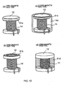
- Figs. 12(a) to 12(d) are diagrams for explaining the drum-type core manufactured by the method in Fig. 11 and provided with a bond magnet.
- Fig. 12(a) is a diagram showing an example of an open magnetic path type in which a viscous material 51 a is formed on the outer peripheral surface of the flange portion 12 in the circumferential direction.
- Fig. 12(b) is a diagram showing another example of the open magnetic path type in which a viscous material 51b is formed on the end surface of the flange portion 12 in the circumferential direction.
- Fig. 12(a) is a diagram showing an example of an open magnetic path type in which a viscous material 51 a is formed on the outer peripheral surface of the flange portion 12 in the circumferential direction.
- Fig. 12(b) is a diagram showing another example of the open magnetic path type in which a viscous material 51b is formed on the end surface of the flange portion 12 in the circumferential direction.
- FIG. 12(c) is a diagram showing an example of a closed magnetic path type in which a viscous material 51 c is formed between the outer peripheral surface of the flange portion 12 and an inner peripheral surface of a cylindrical core 14a.
- Fig. 12(d) is a diagram showing still another example of the open magnetic path type in which a viscous material 51d is formed to bury a coil 14.
- Fig. 13 is a diagram for explaining a method of applying a magnetic field to the viscous material 51d applied on a drum-type core 13 according to this invention.
- Fig. 13(a) is a diagram showing the case where a disk magnet 16 is used.
- Fig. 13(b) is a diagram showing the case where a ring magnet 17 is used.
- Fig. 13(c) is a diagram showing the case where the coil 15 is self-energized.
- an orientation magnetic field in a radial direction can be applied to the ring-shaped (or circular) viscous material 51d applied to the drum-type core 13.
- a high-performance bond magnet oriented (magnetized) in the radial direction can be obtained.
- the Sm 2 Fe 17 N bond magnet and the Sm 2 Co 17 bond magnet were prepared in the manner similar to Example 1 after 50 vol% of a polypropylene resin being a thermoplastic resin and having a softening point of about 80°C was added as a binder to the Sm 2 Fe 17 N alloy magnetic powder and the Sm 2 Co 17 alloy magnetic powder and a resultant mixture was hot-kneaded by a Labo Plastomill.
- the bond magnets thus prepared were inserted into gap portions of center legs of magnetic cores same in shape as the magnetic core used in Example 2 and made of MnZn ferrite to obtain samples. After the under-mentioned measurement, the specific resistances of the bond magnets thus obtained were measured. As a result, the specific resistances were within the range of about 10 to 30 ⁇ cm.
- the Ba ferrite sintered magnet was processed into a shape corresponding to the gap portion of the center leg of the core.
- the magnet was inserted into the gap of the core and magnetized in a magnetic path direction by a pulse magnetizer.
- Each core was subjected to coil winding.
- DC superposition characteristics of the samples were repeatedly measured five times under the conditions of the AC magnetic field frequency of 100 kHz and the superposed magnetic field of 0 to 200 Oe.
- a superposed current was applied so that the direction of the DC bias magnetic field was opposite to the orientation direction or the magnetization direction of the magnetized magnet.
- the permeability was calculated from a core constant and the number of turns of winding.
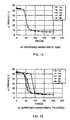
- the first through the fifth measurement results of each core are shown in Figs. 14 to 17 .
- Fig. 14 shows a measurement result of a core without a magnet in a gap for the purpose of comparison.
- Fig. 15 it is understood that, in the core in which a ferrite magnet having a coercive force as small as 4 kOe was inserted, the DC superposition characteristic is considerably deteriorated as the number of times of measurement is increased.
- Figs. 16 and 17 it is understood that those cores in which a bond magnet having a large coercive force exhibit a very stable characteristic without substantial change even in repeated measurements.
- the ferrite magnet since the ferrite magnet has a small coercive force, demagnetization or magnetic reversal is caused by a reverse magnetic field applied to the magnet and, therefore, the DC superposition characteristic is deteriorated. Furthermore, it has been understood that the DC superposition characteristic is excellent if the magnet inserted (or formed) in the core is a rare earth bond magnet having a coercive force of 5 kOe or more.
- Bond magnets were prepared in the manner similar to Example 5 after 40 vol% of a polyethylene resin as a binder was added to Sm 2 Co 17 alloy magnetic powders having average particle sizes of about 1.0 ⁇ m, 2.0 ⁇ m, 25 ⁇ m, 50 ⁇ m, and 75 ⁇ m and a resultant mixture was hot-kneaded by a Labo Plastomill. The characteristics of the bond magnets were measured by a VSM and corrected using demagnetizing field coefficients of the powders. As a result, it was found out that the intrinsic coercive force of 5 kOe or more was obtained for all the magnets. In the manner similar to Example 5, the bond magnets were inserted into gaps of cores.
- the core loss is large at the average particle size of 1.0 ⁇ m because oxidation of the alloy magnetic powder is promoted since the surface area of the alloy magnetic powder is large.
- the core loss is large at the average particle size of 75 ⁇ m because an eddy-current loss becomes large since the average particle size of the alloy magnetic powder is large.
- the surface magnetic flux is high at the average particle size of 1.0 ⁇ m because magnetization is difficult due to a large coercive force.
- the Sm 2 Fe 17 N bond magnet and the Sm 2 Co 17 bond magnet were prepared by mixing each of the Sm 2 Fe 17 N alloy magnetic powder and the Sm 2 Co 17 alloy magnetic powder and 50 vol% of a polyimide resin being a thermoplastic resin and having a softening point of about 300°C as a binder. Then, in the manner same as Example 2, the bond magnets were inserted into gap portions of center legs of magnetic cores made of MnZn ferrite and similar to the magnetic core used in Example 5 to obtain samples. After the under-mentioned measurement, the specific resistances of the bond magnets were measured. As a result, the specific resistances were within the range of about 10 to 30 ⁇ cm.
- the Ba ferrite sintered magnet was processed into a shape corresponding to the gap portion of the center leg of the core.
- the magnet was inserted into the gap of the core and magnetized in a magnetic path direction by a pulse magnetizer.
- each core was subjected to coil winding.
- DC superposition characteristics of the samples were measured.
- the permeability was calculated from a core constant and the number of turns of winding.
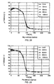
- the results are shown in Fig. 18 .
- Aafter measurement, each sample was held in a constant-temperature bath at 270°C as a condition of a reflow furnace for 1 hour, then cooled to a room temperature, and left for 2 hours. Thereafter, in the manner similar to that mentioned above, the DC superposition characteristics of the samples were measured by the LCR meter. The results are also shown in Fig. 18 .
- a sample without a magnet inserted in a gap portion was prepared in the manner similar to that described above.
- the alloy magnetic powders had an average particle size of 3 to 3.5 ⁇ m.
- 50 vol% of a polyimide resin being a thermoplastic resin and having a softening point of about 300°C was added as a binder and mixed. Thereafter, in the manner similar to Example 5, the bond magnets were arranged in the center legs of ferrite magnetic cores. After the under-mentioned measurement, the specific resistances of the bond magnet were measured. As a result, the specific resistances were within the range of about 10 to 30 ⁇ cm.
- each core was subjected to coil winding.
- DC superposition characteristics of the samples were measured.
- the permeability was calculated from a core constant and the number of turns of winding.
- the results are shown in Fig. 19 .
- each sample was held in a constant-temperature bath at 270°C as a condition of a reflow furnace for 1 hour, and cooled to a room temperature. Thereafter, in the manner similar to that mentioned above, the DC superposition characteristics of the samples were measured by the LCR meter. The results are also shown in Fig. 19 .
- a sample without a magnet inserted in a gap portion was prepared in the manner similar to that described above.
- a SM 2 Co 17 -based sintered magnet having an energy product of about 28 MGOe was coarsely ground and then finely ground by a ball mill in an organic solvent.
- alloy magnetic powders having average particle sizes 150 ⁇ m, 100 ⁇ m, 50 ⁇ m, 10 ⁇ m, 5.6 ⁇ m, 3.3 ⁇ m, 2.4 ⁇ m, and 1.8 ⁇ m were prepared.
- the alloy magnetic powders thus prepared were magnetized to obtain magnetic alloy powders.
- 10 wt% of an epoxy resin was mixed as a binder with each of the magnetic alloy powders to prepare bond magnets in the manner similar to Example 1.
- the characteristics of the bond magnets were measured by a VSM and corrected using demagnetization coefficients of the magnetic alloy powders. The corrected values are shown in Table 3.
- Table 3 average particle size 150 ⁇ m 100 ⁇ m 50 ⁇ m 10 ⁇ m 5.6 ⁇ m 3.3 ⁇ m 2.5 ⁇ m 1.8 ⁇ m Br(Kg) 3.5 3.4 3.3 3.1 3.0 2.8 2.6 2.2 Hc(kOe) 25.6 24.5 23.2 21.5 19.3 16.4 12.5 9.5
- Table 4 average particle size no magnet 150 ⁇ m 100 ⁇ m 50 ⁇ m 10 ⁇ m 5.6 ⁇ m 3.3 ⁇ m 2.5 ⁇ m 1.8 ⁇ m core loss (kW/m 3 ) 520 1280 760 570 560 555 550 520 520 520
- the second-generation Sm 2 Co 17 magnet was subjected to aging at 800°C for 1.5 hours.
- the third-generation Sm 2 Co 17 magnet was subjected to aging at 800°C for 10 hours.
- the coercive forces of the second-generation sintered magnet and the third-generation sintered magnet were 8 kOe and 20 kOe, respectively. These sintered magnets were coarsely ground and then finely ground by a ball mill in an organic solvent to obtain magnetic alloy powders.
- the magnetic alloy powders thus prepared were magnetized to obtain alloy magnetic powders. 50 vol% of an epoxy resin was mixed as a binder with each of the alloy magnetic powders. Thus, bond magnets were prepared in the manner similar to Example 1.
- the bond magnets were inserted into gaps of MnZn-based ferrite cores in the manner similar to Example 5 and subjected to coil winding.
- the DC superposition characteristic of each sample was measured.
- the permeability was calculated from the core constant and the number of turns of windings. The results are shown in Fig. 21 .
- the samples were held in a constant-temperature bath at 270°C as a condition of a reflow furnace for 1 hour, and cooled to a room temperature. Thereafter, in the manner similar to that mentioned above, the DC superposition characteristics of the samples were measured by the LCR meter. The results are also shown in Fig. 21 .
- Example 1 a binder (epoxy resin) in an amount of 40 vol% of the total volume was added to each powder mixture and mixed. Then, in the manner same as Example 1, bond magnets were prepared. The bond magnets thus obtained were inserted into gaps of cores similar to that in Example 5 to obtain samples. Next, the samples were subjected to heat treatment at 270°C in atmospheric air, and taken out from a furnace every 30 minutes. The DC superposition characteristics and the core loss characteristics were measured.
- a binder epoxy resin
- the DC superposition characteristics were measured by an 4284A LCR meter manufactured by Hewlett-Packard under the conditions of the AC magnetic field frequency of 100 kHz and the superposed magnetic field of 0 to 200 Oe. At this time, a superposed current was applied so that the direction of the DC bias magnetic field was opposite to the orientation upon formation of the magnet. The measurement results are shown in Figs. 22 to 31 .
- a mixture of an Sm-Co magnetic alloy powder (average particle size of about 3 ⁇ m) and 3 wt% Zn + 2 wt% Mg and a mixture of the same magnetic alloy powder and 3 wt% Mg + 2 wt% Al were prepared and subjected to heat treatment for 2 hours in an Ar atmosphere at 600°C.
- Each magnetic alloy powder was subjected to metal coating.
- a binder epoxy resin
- bond magnets were prepared.
- the bond magnets were inserted into gaps of cores similar to that in Example 5 to obtain samples.
- the samples were subjected to heat treatment at 270°C in atmospheric air. The samples were taken out from a furnace every hour until the heat treatment time reached 4 hours in total and every 2 hours thereafter, and the flux was measured.
- the flux characteristics of the magnets were measured by a TDF-5 digital flux meter manufactured by TOEI. The measurement results are shown in Table 7 with respect to the flux amount before heat treatment as 100%. Table 7 heat treatment time 0 1 2 3 4 6 8 10 no coating 100 72 61 53 45 36 30 26 Zn 3 Wt%+Mg 2 wt% 100 98 97 97 96 95 94 94 Mg 3 wt%+Al 2 wt% 100 98 98 97 96 96 95 94
- the magnet without metal coating was demagnetized by more than 70% after 10 hours.
- the magnets coated with the above-mentioned metals were demagnetized by about 6% after 10-hour heat treatment.
- the deterioration was very small and the stable characteristics were exhibited. Presumably, this is because oxidation is suppressed by coating the surface of the magnet with the metal to thereby suppress reduction of the flux.
- the invention is applicable to any device using a permanent magnet.
Landscapes
- Engineering & Computer Science (AREA)
- Power Engineering (AREA)
- Manufacturing & Machinery (AREA)
- Chemical & Material Sciences (AREA)
- Composite Materials (AREA)
- Manufacturing Cores, Coils, And Magnets (AREA)
- Hard Magnetic Materials (AREA)
Claims (12)
- Verfahren zum Herstellen eines Verbundmagneten, in dem
ein magnetisches Legierungspulver, das im Voraus magnetisiert wurde, mit einem Harz in einem Gewichtsverhältnis von 3 bis 30% zu dem magnetischen Legierungspulver gemischt wird, um ein viskoses Material von 10 Poise oder mehr zu gewinnen,
das viskose Material an einer vorbestimmten Stelle einer magnetischen Vorrichtung in Kontakt mit dieser angeordnet wird und
ein Magnetfeld an das viskose Material angelegt wird, das in Kontakt mit der magnetischen Vorrichtung angeordnet ist, um das in dem viskosen Material enthaltene magnetische Legierungspulver magnetisch auszurichten, während das Harz ausgehärtet wird, und dadurch den Verbundmagneten an der vorbestimmten Stelle einer magnetischen Vorrichtung in Kontakt mit dieser zu bilden. - Verfahren zum Herstellen eines Verbundmagneten gemäß Anspruch 1, bei dem
das magnetische Legierungspulver mit zumindest einem Metallpulver, das gewählt ist aus Zn, Al, Bi, Ga, In, Mg, Pb, Sb und Sn oder einem Metallpulver einer Legierung davon gemischt wird, um eine Mischung zu gewinnen, bevor das magnetische Legierungspulver mit dem Harz gemischt wird, und
die Mischung einer Wärmebehandlung unterworfen wird, um die Oberfläche des magnetischen Legierungspulvers mit einer Metallschicht zu überziehen. - Verfahren zum Herstellen eines Verbundmagneten gemäß Anspruch 1 oder 2, bei dem
als magnetisches Legierungspulver ein magnetisches Pulver einer seltenen Erde verwendet wird, das eine Koerzitivkraft von nicht weniger als 5 kOe, eine Curie-Temperatur von nicht weniger als 300 °C und eine durchschnittliche Partikelgröße von 2,0 bis 50 µm aufweist. - Verfahren zum Herstellen eines Verbundmagneten gemäß Anspruch 1 oder 2, bei dem
als magnetisches Legierungspulver ein magnetisches Pulver einer seltenen Erde verwendet wird, das eine Koerzitivkraft von nicht weniger als 10 kOe, eine Curie-Temperatur von nicht weniger als 500 °C und eine durchschnittliche Partikelgröße von 2,5 bis 50 µm aufweist. - Verfahren zum Herstellen eines Verbundmagneten gemäß Anspruch 4, bei dem
als magnetisches Legierungspulver ein magnetisches Pulver einer seltenen Erde mit einer Zusammensetzung von Sm(Cobal.Fe0.15-0.25Cu0.06-0.08Zr0.02-0.03)7.0-8.5 verwendet wird. - Verfahren zum Herstellen eines Verbundmagneten gemäß einem der Ansprüche 1 bis 5, bei dem
als Harz eines von einem Polyimidharz, einem Epoxidharz, einem Polyphenylen-Sulfidharz, einem Silikonharz, einem Polyesterharz, einem aromatischen Nylon oder einem Flüssigkristallpolymer verwendet wird. - Verbundmagnet, der mit dem Verfahren gemäß einem der Ansprüche 1 bis 6 hergestellt wurde.
- Magnetische Vorrichtung, die den Verbundmagneten gemäß Anspruch 7 enthält.
- Verfahren zum Herstellen einer magnetischen Vorrichtung, die einen Verbundmagneten enthält, wobei das Verfahren das Herstellen eines Verbundmagneten mit einem Verfahren gemäß Anspruch 1 enthält.
- Verfahren zum Herstellen einer magnetischen Vorrichtung, die einen Verbundmagneten enthält, gemäß Anspruch 9, bei dem
die vorbestimmte Stelle ein Paar Oberflächen ist, die einander gegenüber liegen und einen magnetischen Spalt bilden, und
das viskose Material so in dem magnetischen Spalt angeordnet wird, dass das viskose Material in Kontakt mit beiden Oberflächen gebracht wird. - Verfahren zum Herstellen einer magnetischen Vorrichtung, die einen Verbundmagneten enthält, gemäß Anspruch 9, bei dem
die vorbestimmte Stelle eine Endfläche eines Rollenkerns oder eine äußere Umfangsfläche eines Flanschabschnitts ist, und
das viskose Material in Ringform auf die Endfläche oder die äußere Umfangsfläche des Flanschabschnitts aufgebracht wird. - Magnetische Vorrichtung, die unter Verwendung des Verfahrens gemäß einem der Ansprüche 10 bis 12 hergestellt wurde, wobei der Verbundmagnet ohne Verwendung eines Klebers in engem Kontakt an der vorbestimmten Stelle befestigt ist.
Applications Claiming Priority (5)
| Application Number | Priority Date | Filing Date | Title |
|---|---|---|---|
| JP2002273362 | 2002-09-19 | ||
| JP2002273362 | 2002-09-19 | ||
| JP2003019892 | 2003-01-29 | ||
| JP2003019892 | 2003-01-29 | ||
| PCT/JP2003/011970 WO2004027795A1 (ja) | 2002-09-19 | 2003-09-19 | ボンド磁石の製造方法及びボンド磁石を備えた磁気デバイスの製造方法 |
Publications (3)
| Publication Number | Publication Date |
|---|---|
| EP1548765A1 EP1548765A1 (de) | 2005-06-29 |
| EP1548765A4 EP1548765A4 (de) | 2006-01-11 |
| EP1548765B1 true EP1548765B1 (de) | 2009-07-22 |
Family
ID=32032875
Family Applications (1)
| Application Number | Title | Priority Date | Filing Date |
|---|---|---|---|
| EP03797685A Expired - Lifetime EP1548765B1 (de) | 2002-09-19 | 2003-09-19 | Verfahren zur herstellung eines gebondeten magneten und verfahren zur herstellung einer magnetischen einrichtung mit gebondetem magnet |
Country Status (6)
| Country | Link |
|---|---|
| US (1) | US7531050B2 (de) |
| EP (1) | EP1548765B1 (de) |
| JP (1) | JP4358743B2 (de) |
| CN (1) | CN100390908C (de) |
| DE (1) | DE60328506D1 (de) |
| WO (1) | WO2004027795A1 (de) |
Families Citing this family (19)
| Publication number | Priority date | Publication date | Assignee | Title |
|---|---|---|---|---|
| JP2006114536A (ja) * | 2004-10-12 | 2006-04-27 | Nec Tokin Corp | 線輪部品およびその製造方法 |
| US8004379B2 (en) * | 2007-09-07 | 2011-08-23 | Vishay Dale Electronics, Inc. | High powered inductors using a magnetic bias |
| CN101989485A (zh) * | 2009-07-31 | 2011-03-23 | 株式会社田村制作所 | 电感器 |
| CN102157260B (zh) * | 2010-12-09 | 2013-01-02 | 常山科升电力设备有限公司 | 饼式辐射型导磁铁芯的整体裸浇铸方法 |
| US20150028980A1 (en) * | 2012-09-25 | 2015-01-29 | Delta Electronics, Inc. | Transformer |
| US9607749B2 (en) * | 2014-01-23 | 2017-03-28 | Veris Industries, Llc | Split core current transformer |
| MX387301B (es) | 2014-02-19 | 2025-03-11 | Hutchinson | Procedimiento para la preparación de una composición de electrodo que tiene propiedades magnéticas, una mezcla y una composición que se obtienen por medio de este procedimiento, y este electrodo en sí. |
| JP2015228762A (ja) * | 2014-06-02 | 2015-12-17 | 日東電工株式会社 | 永久磁石、永久磁石の製造方法、回転電機及び回転電機の製造方法 |
| KR102668598B1 (ko) * | 2016-11-28 | 2024-05-24 | 삼성전기주식회사 | 권선형 파워 인덕터 |
| KR102680003B1 (ko) * | 2016-12-05 | 2024-07-02 | 삼성전기주식회사 | 코일부품 |
| CN106449043A (zh) * | 2016-12-09 | 2017-02-22 | 徐超 | 一种变压器磁芯 |
| CN106658314B (zh) * | 2017-03-18 | 2019-08-27 | 歌尔股份有限公司 | 一体式磁铁音圈组件及设有该组件的动磁式扬声器 |
| JP6599933B2 (ja) | 2017-06-29 | 2019-10-30 | 矢崎総業株式会社 | ノイズフィルタ及びノイズ低減ユニット |
| DE102018112683A1 (de) | 2017-07-03 | 2019-01-03 | Fuji Polymer Industries Co., Ltd. | Verfahren und Vorrichtung zum Herstellen eines radial ausgerichteten magnetorheologischen Elastomer-Formkörpers |
| CN110124302B (zh) * | 2019-06-13 | 2024-05-14 | 泉州港花游艺用品工贸有限公司 | 一种防爆裂麻将及制造工艺 |
| WO2021187074A1 (ja) * | 2020-03-19 | 2021-09-23 | Tdk株式会社 | 磁石構造体、回転角度検出器、及び、電動パワーステアリング装置 |
| US20220208446A1 (en) * | 2020-12-30 | 2022-06-30 | Power Integrations, Inc. | Energy transfer element magnetized after assembly |
| JP2023093013A (ja) * | 2021-12-22 | 2023-07-04 | ミネベアミツミ株式会社 | 永久磁石の製造方法および永久磁石 |
| CN117444202A (zh) * | 2023-11-23 | 2024-01-26 | 瑞声开泰科技(马鞍山)有限公司 | 填充成型模具及填充成型方法、烧结NdFeB磁体制备方法 |
Family Cites Families (25)
| Publication number | Priority date | Publication date | Assignee | Title |
|---|---|---|---|---|
| US3985588A (en) * | 1975-02-03 | 1976-10-12 | Cambridge Thermionic Corporation | Spinning mold method for making permanent magnets |
| JPS58157118A (ja) | 1982-03-12 | 1983-09-19 | Seiko Epson Corp | 樹脂結合型希土類コバルト磁石の製造方法 |
| JPS6010605A (ja) * | 1983-06-30 | 1985-01-19 | Hitachi Metals Ltd | インダクタンス素子用永久磁石 |
| US4558077A (en) * | 1984-03-08 | 1985-12-10 | General Motors Corporation | Epoxy bonded rare earth-iron magnets |
| JPS60235416A (ja) | 1984-05-08 | 1985-11-22 | Seiko Epson Corp | 永久磁石の製造方法 |
| JPH0626169B2 (ja) | 1984-12-27 | 1994-04-06 | ティーディーケイ株式会社 | 希土類磁石の磁場中成型方法及び装置 |
| JPS62167368A (ja) * | 1986-01-17 | 1987-07-23 | Sumitomo Metal Mining Co Ltd | 磁性被膜形成用ペ−スト |
| JPH02153507A (ja) | 1989-10-31 | 1990-06-13 | Seiko Epson Corp | 樹脂結合型永久磁石の製造方法 |
| JPH0670930B2 (ja) * | 1990-04-20 | 1994-09-07 | 田淵電機株式会社 | 分割型誘導電磁器の製造方法 |
| JPH05101955A (ja) | 1991-10-03 | 1993-04-23 | Mitsubishi Materials Corp | 異方性ボンド磁石製造装置 |
| JPH05175022A (ja) | 1991-12-20 | 1993-07-13 | Tdk Corp | 磁石の製造方法およびボンディッド磁石 |
| JPH05190311A (ja) | 1992-01-17 | 1993-07-30 | Tdk Corp | 磁石の製造方法および磁石粉末 |
| JP3191021B2 (ja) * | 1992-07-03 | 2001-07-23 | 日立金属株式会社 | 磁性塗料、エンコーダ用の磁性層及びこの形成方法 |
| JPH0786070A (ja) | 1993-06-29 | 1995-03-31 | Tokin Corp | ボンド磁石の製造方法 |
| JP2516176B2 (ja) | 1993-12-24 | 1996-07-10 | セイコーエプソン株式会社 | 樹脂結合型永久磁石の製造方法 |
| JPH07201544A (ja) | 1993-12-29 | 1995-08-04 | Sankyo Seiki Mfg Co Ltd | 樹脂結合型磁石 |
| JP4003906B2 (ja) | 1999-03-19 | 2007-11-07 | コバレントマテリアル株式会社 | シリコン単結晶半導体ウエハ加熱処理用治具及びこれを用いたシリコン単結晶半導体ウエハ加熱処理用装置 |
| JP2000290541A (ja) * | 1999-04-08 | 2000-10-17 | Idemitsu Atochem Kk | 磁性粉末を含むインキ用又は塗料用組成物 |
| JP2001207201A (ja) | 1999-11-17 | 2001-07-31 | Sumitomo Metal Mining Co Ltd | 磁石用Sm−Fe−N系被覆合金粉末及びその製造方法 |
| JP4084007B2 (ja) | 2000-07-24 | 2008-04-30 | 吟也 足立 | 磁性材料の製造方法 |
| CN1252749C (zh) * | 2000-10-25 | 2006-04-19 | Nec东金株式会社 | 具有磁偏用磁体的磁芯和采用它的电感部件 |
| JP2002134327A (ja) * | 2000-10-26 | 2002-05-10 | Tokin Corp | インダクタ部品 |
| JP2002198211A (ja) * | 2000-12-26 | 2002-07-12 | Sumitomo Metal Mining Co Ltd | 高耐候性磁石粉末の製造方法及び得られる製品 |
| JP2002222707A (ja) * | 2001-01-26 | 2002-08-09 | Nec Tokin Corp | インダクタンス部品 |
| JP4560246B2 (ja) | 2001-07-05 | 2010-10-13 | キヤノン株式会社 | 印刷装置およびその制御方法およびプログラム |
-
2003
- 2003-09-19 JP JP2004537995A patent/JP4358743B2/ja not_active Expired - Fee Related
- 2003-09-19 DE DE60328506T patent/DE60328506D1/de not_active Expired - Lifetime
- 2003-09-19 EP EP03797685A patent/EP1548765B1/de not_active Expired - Lifetime
- 2003-09-19 WO PCT/JP2003/011970 patent/WO2004027795A1/ja not_active Ceased
- 2003-09-19 US US10/528,305 patent/US7531050B2/en not_active Expired - Lifetime
- 2003-09-19 CN CNB038222396A patent/CN100390908C/zh not_active Expired - Fee Related
Also Published As
| Publication number | Publication date |
|---|---|
| JP4358743B2 (ja) | 2009-11-04 |
| WO2004027795A1 (ja) | 2004-04-01 |
| EP1548765A4 (de) | 2006-01-11 |
| CN100390908C (zh) | 2008-05-28 |
| CN1682327A (zh) | 2005-10-12 |
| US20060280921A1 (en) | 2006-12-14 |
| DE60328506D1 (de) | 2009-09-03 |
| EP1548765A1 (de) | 2005-06-29 |
| JPWO2004027795A1 (ja) | 2006-01-19 |
| US7531050B2 (en) | 2009-05-12 |
Similar Documents
| Publication | Publication Date | Title |
|---|---|---|
| EP1548765B1 (de) | Verfahren zur herstellung eines gebondeten magneten und verfahren zur herstellung einer magnetischen einrichtung mit gebondetem magnet | |
| US6710693B2 (en) | Inductor component containing permanent magnet for magnetic bias and method of manufacturing the same | |
| JPWO2002021543A1 (ja) | 永久磁石、それを磁気バイアス用磁石とした磁気コア、およびそれを用いたインダクタンス部品 | |
| CN101303929B (zh) | 放射状各向异性环形磁铁 | |
| CN101499343A (zh) | 复合软磁粉材料及永磁偏置磁芯 | |
| EP1211699A2 (de) | Magnetkern mit Polarisierungsmagnet und Induktor-Komponent | |
| EP1717828A1 (de) | Verfahren zur herstellung eines radialen anisotropen zylindrischen gesinterten magneten und zylinder-multipolmagnet zur verwendung in einem permanentmagnetmotor | |
| EP1713098B1 (de) | Radialer anisotroper zylindrischer gesinteter magnet und permanentmagnetmotor | |
| JP4605317B2 (ja) | 希土類異方性ボンド磁石の製造方法、磁石成形体の配向処理方法および磁場中成形装置 | |
| JP7835652B2 (ja) | 磁気エンコーダの製造方法 | |
| JP2553843B2 (ja) | 耐食性のすぐれた永久磁石の製造方法 | |
| WO2024203792A1 (ja) | 磁気エンコーダ | |
| JP2012079822A (ja) | 希土類異方性磁石の製造方法 | |
| JP2002231540A (ja) | 磁気バイアス用磁石を有する磁気コア及びそれを用いたインダクタンス部品 | |
| JP4226817B2 (ja) | 磁気バイアス用磁石を有する磁気コア及びそれを用いたインダクタンス部品 | |
| Brown et al. | The comparison of anisotropic (and isotropic) powders for polymer bonded Rare-Earth permanent magnets | |
| WO2025164560A1 (ja) | 多極磁石の製造方法 | |
| JPH0471205A (ja) | ボンド磁石の製造方法 | |
| JP2003059727A (ja) | 磁気コア及びそれを用いたインダクタンス部品 | |
| JP2002343661A (ja) | 筒状ボンド磁石及びコアレスモータ | |
| JP2004356152A (ja) | 磁芯およびそれを用いたインダクタンス部品 | |
| JP2005148499A (ja) | マグネットローラ | |
| JP2003257767A (ja) | 永久磁石の製造方法およびプレス装置 | |
| JPH06333729A (ja) | 異方性磁石、その製造方法および製造装置 | |
| JP2003257753A (ja) | 磁気コアおよびインダクタンス部品 |
Legal Events
| Date | Code | Title | Description |
|---|---|---|---|
| PUAI | Public reference made under article 153(3) epc to a published international application that has entered the european phase |
Free format text: ORIGINAL CODE: 0009012 |
|
| 17P | Request for examination filed |
Effective date: 20050413 |
|
| AK | Designated contracting states |
Kind code of ref document: A1 Designated state(s): AT BE BG CH CY CZ DE DK EE ES FI FR GB GR HU IE IT LI LU MC NL PT RO SE SI SK TR |
|
| A4 | Supplementary search report drawn up and despatched |
Effective date: 20051124 |
|
| RBV | Designated contracting states (corrected) |
Designated state(s): DE FR GB |
|
| 17Q | First examination report despatched |
Effective date: 20080829 |
|
| GRAP | Despatch of communication of intention to grant a patent |
Free format text: ORIGINAL CODE: EPIDOSNIGR1 |
|
| GRAS | Grant fee paid |
Free format text: ORIGINAL CODE: EPIDOSNIGR3 |
|
| GRAA | (expected) grant |
Free format text: ORIGINAL CODE: 0009210 |
|
| AK | Designated contracting states |
Kind code of ref document: B1 Designated state(s): DE FR GB |
|
| REG | Reference to a national code |
Ref country code: GB Ref legal event code: FG4D |
|
| REF | Corresponds to: |
Ref document number: 60328506 Country of ref document: DE Date of ref document: 20090903 Kind code of ref document: P |
|
| PLBE | No opposition filed within time limit |
Free format text: ORIGINAL CODE: 0009261 |
|
| STAA | Information on the status of an ep patent application or granted ep patent |
Free format text: STATUS: NO OPPOSITION FILED WITHIN TIME LIMIT |
|
| 26N | No opposition filed |
Effective date: 20100423 |
|
| PGFP | Annual fee paid to national office [announced via postgrant information from national office to epo] |
Ref country code: GB Payment date: 20120927 Year of fee payment: 10 |
|
| PGFP | Annual fee paid to national office [announced via postgrant information from national office to epo] |
Ref country code: DE Payment date: 20120928 Year of fee payment: 10 |
|
| PGFP | Annual fee paid to national office [announced via postgrant information from national office to epo] |
Ref country code: FR Payment date: 20121012 Year of fee payment: 10 |
|
| GBPC | Gb: european patent ceased through non-payment of renewal fee |
Effective date: 20130919 |
|
| REG | Reference to a national code |
Ref country code: DE Ref legal event code: R119 Ref document number: 60328506 Country of ref document: DE Effective date: 20140401 |
|
| REG | Reference to a national code |
Ref country code: FR Ref legal event code: ST Effective date: 20140530 |
|
| PG25 | Lapsed in a contracting state [announced via postgrant information from national office to epo] |
Ref country code: GB Free format text: LAPSE BECAUSE OF NON-PAYMENT OF DUE FEES Effective date: 20130919 |
|
| PG25 | Lapsed in a contracting state [announced via postgrant information from national office to epo] |
Ref country code: DE Free format text: LAPSE BECAUSE OF NON-PAYMENT OF DUE FEES Effective date: 20140401 Ref country code: FR Free format text: LAPSE BECAUSE OF NON-PAYMENT OF DUE FEES Effective date: 20130930 |