EP1543786A2 - Behandlungsinstrument für Endoskop - Google Patents
Behandlungsinstrument für Endoskop Download PDFInfo
- Publication number
- EP1543786A2 EP1543786A2 EP04030195A EP04030195A EP1543786A2 EP 1543786 A2 EP1543786 A2 EP 1543786A2 EP 04030195 A EP04030195 A EP 04030195A EP 04030195 A EP04030195 A EP 04030195A EP 1543786 A2 EP1543786 A2 EP 1543786A2
- Authority
- EP
- European Patent Office
- Prior art keywords
- treatment
- grabbing
- beak
- instrument according
- treatment instrument
- Prior art date
- Legal status (The legal status is an assumption and is not a legal conclusion. Google has not performed a legal analysis and makes no representation as to the accuracy of the status listed.)
- Granted
Links
Images


Classifications
-
- A—HUMAN NECESSITIES
- A61—MEDICAL OR VETERINARY SCIENCE; HYGIENE
- A61B—DIAGNOSIS; SURGERY; IDENTIFICATION
- A61B17/00—Surgical instruments, devices or methods, e.g. tourniquets
- A61B17/28—Surgical forceps
- A61B17/29—Forceps for use in minimally invasive surgery
-
- A—HUMAN NECESSITIES
- A61—MEDICAL OR VETERINARY SCIENCE; HYGIENE
- A61B—DIAGNOSIS; SURGERY; IDENTIFICATION
- A61B1/00—Instruments for performing medical examinations of the interior of cavities or tubes of the body by visual or photographical inspection, e.g. endoscopes; Illuminating arrangements therefor
- A61B1/00064—Constructional details of the endoscope body
- A61B1/00071—Insertion part of the endoscope body
- A61B1/0008—Insertion part of the endoscope body characterised by distal tip features
- A61B1/00087—Tools
-
- A—HUMAN NECESSITIES
- A61—MEDICAL OR VETERINARY SCIENCE; HYGIENE
- A61B—DIAGNOSIS; SURGERY; IDENTIFICATION
- A61B17/00—Surgical instruments, devices or methods, e.g. tourniquets
- A61B17/16—Bone cutting, breaking or removal means other than saws, e.g. Osteoclasts; Drills or chisels for bones; Trepans
- A61B17/1604—Chisels; Rongeurs; Punches; Stamps
- A61B17/1606—Chisels; Rongeurs; Punches; Stamps of forceps type, i.e. having two jaw elements moving relative to each other
- A61B17/1608—Chisels; Rongeurs; Punches; Stamps of forceps type, i.e. having two jaw elements moving relative to each other the two jaw elements being linked to two elongated shaft elements moving longitudinally relative to each other
-
- A—HUMAN NECESSITIES
- A61—MEDICAL OR VETERINARY SCIENCE; HYGIENE
- A61B—DIAGNOSIS; SURGERY; IDENTIFICATION
- A61B17/00—Surgical instruments, devices or methods, e.g. tourniquets
- A61B17/22—Implements for squeezing-off ulcers or the like on the inside of inner organs of the body; Implements for scraping-out cavities of body organs, e.g. bones; Calculus removers; Calculus smashing apparatus; Apparatus for removing obstructions in blood vessels, not otherwise provided for
- A61B17/22031—Gripping instruments, e.g. forceps, for removing or smashing calculi
-
- A—HUMAN NECESSITIES
- A61—MEDICAL OR VETERINARY SCIENCE; HYGIENE
- A61B—DIAGNOSIS; SURGERY; IDENTIFICATION
- A61B17/00—Surgical instruments, devices or methods, e.g. tourniquets
- A61B17/32—Surgical cutting instruments
- A61B17/320016—Endoscopic cutting instruments, e.g. arthroscopes, resectoscopes
-
- A—HUMAN NECESSITIES
- A61—MEDICAL OR VETERINARY SCIENCE; HYGIENE
- A61B—DIAGNOSIS; SURGERY; IDENTIFICATION
- A61B10/00—Other methods or instruments for diagnosis, e.g. instruments for taking a cell sample, for biopsy, for vaccination diagnosis; Sex determination; Ovulation-period determination; Throat striking implements
- A61B10/02—Instruments for taking cell samples or for biopsy
- A61B10/06—Biopsy forceps, e.g. with cup-shaped jaws
-
- A—HUMAN NECESSITIES
- A61—MEDICAL OR VETERINARY SCIENCE; HYGIENE
- A61B—DIAGNOSIS; SURGERY; IDENTIFICATION
- A61B17/00—Surgical instruments, devices or methods, e.g. tourniquets
- A61B17/16—Bone cutting, breaking or removal means other than saws, e.g. Osteoclasts; Drills or chisels for bones; Trepans
- A61B17/1662—Bone cutting, breaking or removal means other than saws, e.g. Osteoclasts; Drills or chisels for bones; Trepans for particular parts of the body
- A61B17/1688—Bone cutting, breaking or removal means other than saws, e.g. Osteoclasts; Drills or chisels for bones; Trepans for particular parts of the body for the sinus or nose
-
- A—HUMAN NECESSITIES
- A61—MEDICAL OR VETERINARY SCIENCE; HYGIENE
- A61B—DIAGNOSIS; SURGERY; IDENTIFICATION
- A61B17/00—Surgical instruments, devices or methods, e.g. tourniquets
- A61B17/00234—Surgical instruments, devices or methods, e.g. tourniquets for minimally invasive surgery
- A61B2017/00292—Surgical instruments, devices or methods, e.g. tourniquets for minimally invasive surgery mounted on or guided by flexible, e.g. catheter-like, means
-
- A—HUMAN NECESSITIES
- A61—MEDICAL OR VETERINARY SCIENCE; HYGIENE
- A61B—DIAGNOSIS; SURGERY; IDENTIFICATION
- A61B17/00—Surgical instruments, devices or methods, e.g. tourniquets
- A61B17/28—Surgical forceps
- A61B17/29—Forceps for use in minimally invasive surgery
- A61B2017/2901—Details of shaft
- A61B2017/2905—Details of shaft flexible
-
- A—HUMAN NECESSITIES
- A61—MEDICAL OR VETERINARY SCIENCE; HYGIENE
- A61B—DIAGNOSIS; SURGERY; IDENTIFICATION
- A61B17/00—Surgical instruments, devices or methods, e.g. tourniquets
- A61B17/28—Surgical forceps
- A61B17/29—Forceps for use in minimally invasive surgery
- A61B2017/2926—Details of heads or jaws
- A61B2017/2932—Transmission of forces to jaw members
- A61B2017/2939—Details of linkages or pivot points
-
- A—HUMAN NECESSITIES
- A61—MEDICAL OR VETERINARY SCIENCE; HYGIENE
- A61B—DIAGNOSIS; SURGERY; IDENTIFICATION
- A61B17/00—Surgical instruments, devices or methods, e.g. tourniquets
- A61B17/32—Surgical cutting instruments
- A61B2017/320064—Surgical cutting instruments with tissue or sample retaining means
Definitions
- the present invention relates to a treatment instrument for an endoscope.
- an operating wire is arranged to insert into a flexible sheath inserted and detached into and from a treatment instrument inserting channel of the endoscope, and treatment pieces arranged at a front end portion of the flexible sheath are made to be able to open and close from a side of the hand by an operating wire (for example, Patent References 1 to 5).
- an outer diameter of the treatment pieces needs to be smaller than an inner diameter of the treatment instrument inserting channel and therefore, only a small-scaled treatment can be carried out in the background art.
- the invention is characterized by having the following arrangement.
- Fig. 1 is a sectional view of a side face in a state in which a grabbing instrument 10 which corresponds to a treatment instrument is attached to a front end portion main body 2 constituting a distal end portion of an endoscope inserting portion 1 made of a flexible tube.
- Fig. 2 is an outlook view
- Fig. 3 is a sectional view taken along a line III-III of Fig. 1.
- a rear half portion of a front end hood 11 provided at the grabbing instrument 10 is formed in a shape of a cylinder having a diameter nearly the same as that of a front end portion of the front end portion main body 2, is formed of a plastic material having an elasticity or the like and can be tightly fitted to fix to the front end portion main body 2 from a front end side thereof by being deformed elastically and can also be detached therefrom.
- the rear half portion and the front end portion main body 2 may be provided with a groove and a projection which are engaged with each other.
- an observing window 3 an illuminating window 4 and a treatment instrument projecting port 5 are arranged at a front end face 2a of the front end portion main body 2, and the front end hood 11 is attached to the front end portion main body 2 such that the front end hood 11 does not obstruct front sides thereof.
- a grabbing member 12 (treatment member) for grabbing a foreign matter or the like so as to direct in a longitudinal direction in a state that a front end portion thereof is projected to a front side from a front end of the front end hood 11, and a supporting shaft 13 is loosely inserted and fitted into a shaft hole 12a formed at a rear end portion of the grabbing member 12.
- the supporting shaft 13 is straightly arranged in a peripheral direction at a position proximate to an inner peripheral face of the front end hood 11, and two end portions 13a thereof are fixedly attached to the front end hood 11 as shown-in Fig. 3. Any means of bonding, welding or the like may be used for the fixing the supporting shaft.
- the grabbing member 12 When the grabbing member 12 is in an opened state shown by bold lines in Fig. 1, the grabbing member 12 is directed straightly in the longitudinal direction and a portion thereof proximate to a front side thereof is projected to a front side from the front end of the front end hood 11, and the grabbing member 12 is disposed in a state of being substantially extended along the inner peripheral face of the front end hood 11. Therefore, the grabbing member 12 hardly obstacles an observing field of view directed from the observing window 3 to the front side.
- the wire may be made of any string such as silk, yarn and the like.
- the grabbing section 12 is connected with respective distal end portions of a pair of operating wires 15 at a position frontward from the shaft hole 12a.
- the pair of operating wires 15 pass through a wire passing hole 11a formed to penetrate the rear half portion of the front end hood 11 in a direction in parallel with an axis line thereof and are arranged to insert loosely into a guide tube 16 extended rearward therefrom over an entire length of the guide tube 16.
- the guide tube 16 is arranged along an outer face of the endoscope inserting portion 1 and is fastened to fix to the endoscope inserting portion 2 by a removable fastening strap 20 or the like (may be an adhering tape or the like) , and a base side (side of the hand) thereof, not illustrated, is connected with an operating portion for operating to extract and retract the operating wire 15.
- a removable fastening strap 20 or the like may be an adhering tape or the like
- the grabbing member 12 when a closing direction operating wire 15a is operated to pull from the side of the hand, as shown by two-dotted chain lines in Fig. 1, the grabbing member 12 is pivoted in a direction of a center axis of the front end hood 11 about the supporting shaft 13 to be brought into a closed state in which the grabbing member 12 is contained inside the front end hood 11 and when an opening direction operating wire 15b is operated to pull from the side of the hand, the grabbing member 12 is brought back to the opened state shown by bold lines.
- three of the grabbing members 12 are arranged around the axis line of the front end hood 11 at intervals of 120° and the three grabbing members 12 are simultaneously operated to open and close by operating to extract and retract the operating wires 15 connected to the respective grabbing members 12 simultaneously from the side of the operating portion.
- the grabbing instrument of the endoscope constituted in this way, when the grabbing instrument is guided into the body along with the endoscope inserting portion 1, the grabbing member 12 is brought into the opened state to observe the front side by the endoscope and when the grabbing instrument passes the stricture portion, inside of the sphincter muscle or the like, the grabbing member 12 is brought into the closed state to prevent the grabbing section 12 from impairing the mucous membrane.
- a foreign matter 100 can be grabbed to recover by directing the grabbing member 12 to the foreign matter 100 to operate from the opened state to the closed state, and the foreign matter 100 having a size of substantially a diameter of the front end hood 11 can easily be recovered. Further, a section including the two grabbing members 12 is illustrated.
- the observing window 3 includes a zoom optical system or the like for enlarged observation
- microscopic enlarged observation can easily be carried out by pressing an affected portion 101 by the grabbing member 12 to fix it.
- incision of the mucous membrane or the like is carried out as shown by Fig. 6, by pressing the affected portion 101 by the grabbing member 12 to fix it, incision of the mucous membrane can safely be carried out by forceps 30 or the like projected from the treatment instrument projecting port 5 and injection or the like can safely be carried out similarly.
- the invention is not limited to the above-described embodiment but, for example, as shown by second and third embodiments shown by Fig. 7 and Fig. 8, there may be provided only one of the grabbing member 12 or two thereof at interval of 180°, or four or more thereof may be arranged.
- the grabbing member 12 can be formed to prolong considerably, and the prolonged grabbing member 12 can completely be contained in the front end hood 11 when the prolonged grabbing member 12 is brought into the closed state.
- two of the grabbing members 12 as shown by Fig. 8 by arranging the two grabbing members 12 to intersect with each other, the grabbing members 12 can be formed to be prolonged considerably, the grabbing members 12 can completely be contained in the front end hood 11.
- the grabbing member 12 When the grabbing member 12 is formed by a material having spring performance, as shown by Fig.8, the foreign matter 100 having a brittleness or the like can be grabbed to recover without destructing the foreign matter 100 by elastically flexing the grabbing members 12 when grabbing the foreign matter 100.
- a variety of shapes of the grabbing member 12 may be provided in accordance with a grabbing object or the like such as, for example, a rake shape as shown by Fig.9, a spoon shape as shown by Fig.10, a crane beak shape as shown by Fig.11, a bifurcated shape as shown by Fig.12, a shape attached with a soft rubber rod at a front end thereof as shown by Fig.13 and so on.
- a grabbing object or the like such as, for example, a rake shape as shown by Fig.9, a spoon shape as shown by Fig.10, a crane beak shape as shown by Fig.11, a bifurcated shape as shown by Fig.12, a shape attached with a soft rubber rod at a front end thereof as shown by Fig.13 and so on.
- the grabbed foreign matter 100 can be cut by exerting a large closing force thereto, further, when the grabbing member 12 is constituted to be able to conduct a high frequency current, hemostasis can also be carried out while cutting the foreign matter 100.
- Fig.19 shows a state of attaching a beak type treatment instrument 110 to an endoscope 101
- reference numeral 102 designates an endoscope inserting portion in a shape of a flexible tube
- reference numeral 103 designates an endoscope operating portion connected to a base end of the endoscope inserting portion 2.
- a rear half portion of a front end hood 111 provided at the beak type treatment instrument 110 constitutes a cylindrical attaching and detaching portion 112 attachable and detachable to and from a front end portion of the endoscope inserting portion 102 by being elastically deformed, and a front side portion of a beak-shaped treatment member 114 arranged at inside of the front end hood 111 is projected frontward from a front end opening portion 113 of the front end hood 111.
- An operating wire guide tube 115 extended rearward from the cylindrical attaching and detaching portion 112 of the front end hood 111 is arranged to a base side of the endoscope inserting portion 112 along an outer face of the endoscope inserting portion 102 and is fastened to fix to the endoscope inserting portion 102 by detachable fastening straps 109 at a plurality of portions thereof in the midway.
- a base end of the operating wire guide tube 115 is connected with an operating portion 120.
- an operating wire 118 inserted into the operating wire guide tube 115 over an entire length thereof is extracted and retracted in an axial line direction to thereby enable to open and close the beak-shaped treatment members 114 in the beak-shaped shape.
- the operating portion 120 is projected with two connection terminals 23 for two positive and negative poles for connecting a high frequency power source cord 130. Therefore, a high frequency treatment of a bipolar (two poles) type can be carried out by connecting two pieces of the operating wires 18 to a positive pole and a negative pole of a high frequency power source, not illustrated, independently from each other, as necessary.
- a high frequency treatment of a monopolar (single pole) type can also be carried out by utilizing the connecting terminal 123 for the positive pole in the two connecting terminals 123, and in the case of carrying out a mechanical treatment without using a high frequency current, the connection terminals 123 may not be utilized.
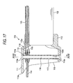
- Fig.15 is a perspective view of a state in which a front end portion of the beak-shaped treatment instrument 110 is not attached to the front end portion of the endoscope inserting portion 102 (however, the state is illustrated by cutting to remove a portion thereof),
- Fig.16 is a sectional view of a side face portion in a state in which the front end portion of the beak-shaped treatment instrument 110 is attached to the front end portion of the endoscope inserting portion 102
- Fig.17 is a sectional view of a plane thereof
- Fig.18 is a sectional view taken along a line XVIII-XVIII of Fig.17.
- the front end hood 111 of the beak type treatment instrument 110 is formed in a cylindrical shape bolder than a diameter of the front end portion of the endoscope inserting portion 102 by a transparent plastic material, and the cylindrical attaching and detaching portion 112 constituting the rear half portion is tightly fitted to the front end portion of the endoscope inserting portion 102.
- the front end portion of the endoscope inserting portion 102 and the cylindrical attaching and detaching portion 112 may be with a groove and a projection which are engaged with each other to fix it.
- An observing window 104, an illuminating window 105 and a suction port 6 or the like are arranged at front end face 102a of the endoscope inserting portion 102, and the front end opening portion 113 is formed over an entire face of a front end portion of the front end hood 111 such that the front end hood 111 does not obstruct front sides thereof.
- the front end hood 111 of the embodiment is formed with a projected end 113a at which a portion thereof proximate to the beak-shaped treatment members 114 is projected to a front side to be longer than other portion.
- a treatment member supporting member 115 in a shape of a round bar for turnably supporting the pair of beak-shaped treatment members 114 in the beak-shaped shape is arranged inside the front end hood 111 in a state of crossing the front end hood in a diameter direction.
- Opposite end portions 116a of the treatment member supporting member 116 are respectively fixed to a side wall of the front end hood 111.
- the fixing is carried out by mechanical clamping, the fixing may be carried out by any means of screwing to adhere, welding or the like.
- the treatment member supporting member 116 may be arranged to deviate from a center of the front end hood 111 to a pertinent position displaced in a radial direction to avoid overlapping with a front side of an effective pupil diameter of the observing window 104 such that the treatment member supporting member 116 does not significantly obstructs an observing field of view by the observing window 104.
- the treatment member supporting member 116 is covered with an electrically insulative insulating pipe 117 of, for example, an ethylene tetrafluoride resin tube or the like.
- the insulating pipe 117 can be omitted when the beak-shaped treatment members 114 carry out only a mechanical treatment.
- the pair of beak-shaped treatment members 114 are formed in a shape of scissors according to the embodiment, and respectively formed with a hole formed at a position functioning as a rotational fulcrum, through which the treatment member supporting member 116 (and the insulating pipe 117) are inserted without rattle but to a degree of not restricting freedom of rotation.
- An insulating spacer 119 made of an insulative is arranged between the pair of beak-shaped treatment members 114, and is provided with a small frictional resistance of, for example, an ethylene tetrafluoride resin sheet or the like by being interposed therebetween.
- the insulating spacer 119 is supported by the treatment member supporting member 116 by passing the treatment member supporting member 116 through a hole bored there.
- illustration of the insulating spacer 119 is omitted in Fig.15 and the insulating spacer 119 can be omitted when the beak-shaped treatment members 114 are not high frequency electrodes of a bipolar type.
- a wire passing hole 115a for passing the pair of operating wires 118 is formed through inside of a wall of the cylindrical attaching and detaching portion 112.
- a front end portion of the operating wire guide tube 115 is inserted thereto from a rear side to be fixed to bond.
- Front end portions of the pair of operating wires 118 are led out from the wire passing hole 115a to the front side and respectively connected to engaging holes 114a formed at vicinities of rear ends of the beak-shaped treatment members 114.
- the pair of beak-shaped treatment members 114 are operated to be opened and closed like the beak-shaped shape about the treatment member supporting member 116. Further, Fig.15 shows a state of opening the beak-shaped treatment members 114 and Fig.16 shows a state of closing the beak-shaped treatment members 114.
- the pair of operating wires 118 are respectively coated with electrically insulative skin films such that the pair of operating wires 118 are not electrically conducted to each other.
- the electrically insulating skin film may be coated only on one of the operating wires 118.
- the beak-shaped treatment instrument 110 constituted in this way is attached to the front end portion of the endoscope inserting portion 102 as shown by respective drawings other than Fig.15 and is inserted into the body.
- the beak-shaped treatment members 114 can easily be inserted without being caught by the body wall or the like.
- a state of the mucous membrane in the body frontward from the front end hood 111 can be observed from the observing window 104 of the endoscope 101, further, since the front end hood 111 is transparent, a surrounding situation can widely be observed also by way of the front end hood 111.
- a size of the beak-shaped treatment members 114 is only restricted by a size of the front end hood 111 containing the beak-shaped treatment members 114 and therefore, the beak-shaped treatment members 114 can be formed much larger than that of the background art, and a large-scaled treatment (sampling, grabbing, incision, ablation, hemostasis or the like) can be carried out at the portions proximate to front ends of the beak-shaped treatment members 114 projected forward from the front end opening portion 113 of the front end hood 111.
- the beak-shaped treatment members 114 may be exerted with a large force, the treatment member supporting member 116 for supporting the beak-shaped treatment members 114 is fixed to the front end hood 111 and is not fluctuated and therefore, the large-scaled treatment can easily and safely be carried out in a stable state.
- the treatment member supporting member 16 may be constituted by a member in a pin-like shape by being arranged to project from a side wall portion of the front end hood 111 to an inner side in a state of a cantilever.
- the beak-shaped treatment members 114 are large grabbing members or the like, when notches 113b for eliminating interference with the front end hood 111 in opening the pair of beak-shaped treatment members 114 in the beak-shaped shape are formed continuously to a rear side from the front end opening portion 113, the beak-shaped treatment members 114 can be opened by a large amount.
- a hemostasis treatment or the like can be carried out by only pressing the front ends of the beak-shaped treatment members 114 to the mucous membrane 100 of the affected part and conducting a high frequency current, conversely in sampling a tissue, even when the high frequency current is not conducted, a large tissue sample can be sampled by only opening and closing the beak-shaped treatment members 114.
Applications Claiming Priority (4)
| Application Number | Priority Date | Filing Date | Title |
|---|---|---|---|
| JP2003421742 | 2003-12-19 | ||
| JP2003421742A JP2005177098A (ja) | 2003-12-19 | 2003-12-19 | 内視鏡用嘴型処置具 |
| JP2004032896 | 2004-02-10 | ||
| JP2004032896A JP2005224262A (ja) | 2004-02-10 | 2004-02-10 | 内視鏡用把持具 |
Publications (3)
| Publication Number | Publication Date |
|---|---|
| EP1543786A2 true EP1543786A2 (de) | 2005-06-22 |
| EP1543786A3 EP1543786A3 (de) | 2005-06-29 |
| EP1543786B1 EP1543786B1 (de) | 2007-05-02 |
Family
ID=34525531
Family Applications (1)
| Application Number | Title | Priority Date | Filing Date |
|---|---|---|---|
| EP04030195A Expired - Fee Related EP1543786B1 (de) | 2003-12-19 | 2004-12-20 | Behandlungsinstrument für Endoskop |
Country Status (3)
| Country | Link |
|---|---|
| US (1) | US7351201B2 (de) |
| EP (1) | EP1543786B1 (de) |
| DE (1) | DE602004006218T2 (de) |
Cited By (3)
| Publication number | Priority date | Publication date | Assignee | Title |
|---|---|---|---|---|
| WO2008025480A1 (de) * | 2006-08-30 | 2008-03-06 | Paul Peschke Gmbh | Chirurgische greifzange |
| WO2008154256A3 (en) * | 2007-06-08 | 2009-03-05 | Medtronic Xomed Inc | Guard device for surgical cutting and evoked potential monitoring system |
| EP3064121A4 (de) * | 2013-11-01 | 2017-09-06 | Olympus Corporation | Endoskopisches behandlungssystem |
Families Citing this family (36)
| Publication number | Priority date | Publication date | Assignee | Title |
|---|---|---|---|---|
| US7771440B2 (en) * | 2005-08-18 | 2010-08-10 | Ethicon Endo-Surgery, Inc. | Method and apparatus for endoscopically performing gastric reduction surgery in a single pass |
| US8702694B2 (en) | 2005-11-23 | 2014-04-22 | Covidien Lp | Auto-aligning ablating device and method of use |
| US20070213702A1 (en) * | 2006-03-08 | 2007-09-13 | Olympus Medical Systems Corp. | Medical procedure carried out via a natural opening |
| US20070219411A1 (en) * | 2006-01-13 | 2007-09-20 | Olympus Medical Systems Corp. | Overtube and endoscopic treatment system |
| US8721657B2 (en) * | 2006-01-13 | 2014-05-13 | Olympus Medical Systems Corp. | Medical instrument |
| US20080255422A1 (en) * | 2006-01-13 | 2008-10-16 | Olympus Medical Systems Corp. | Medical device |
| US20070167675A1 (en) * | 2006-01-13 | 2007-07-19 | Olympus Medical Systems Corp. | Overtube and medical procedure via natural orifice using the same |
| US8728121B2 (en) * | 2006-01-13 | 2014-05-20 | Olympus Medical Systems Corp. | Puncture needle and medical procedure using puncture needle that is performed via natural orifice |
| US8241279B2 (en) | 2006-02-23 | 2012-08-14 | Olympus Medical Systems Corp. | Overtube and natural opening medical procedures using the same |
| US7785333B2 (en) * | 2006-02-21 | 2010-08-31 | Olympus Medical Systems Corp. | Overtube and operative procedure via bodily orifice |
| WO2007106342A2 (en) * | 2006-03-10 | 2007-09-20 | Wilson-Cook Medical Inc. | A clip device and a protective cap for drawing the target tissue into it before the clip is deployed |
| US20070270894A1 (en) * | 2006-05-16 | 2007-11-22 | Zimmon David S | Combined endoscope and biopsy instrument with a removable biopsy cassette for in situ fixation and specimen processing |
| US20110124961A1 (en) * | 2006-05-16 | 2011-05-26 | David Zimmon | Automated actuator for spring based multiple purpose medical instruments |
| CA2659326C (en) * | 2006-08-01 | 2011-02-15 | Wilson-Cook Medical Inc. | Improved system and method for endoscopic treatment of tissue |
| JP4847354B2 (ja) * | 2007-01-22 | 2011-12-28 | オリンパスメディカルシステムズ株式会社 | 内視鏡用処置具 |
| US20080262301A1 (en) * | 2007-04-20 | 2008-10-23 | Wilson-Cook Medical Inc. | Steerable overtube |
| JP4931228B2 (ja) * | 2007-05-28 | 2012-05-16 | Hoya株式会社 | 内視鏡の先端部 |
| JP5159181B2 (ja) * | 2007-06-21 | 2013-03-06 | Hoya株式会社 | 内視鏡における連結部の構造 |
| JP5006708B2 (ja) * | 2007-06-22 | 2012-08-22 | Hoya株式会社 | 内視鏡の回転機構の端部構造 |
| JP5137477B2 (ja) * | 2007-06-22 | 2013-02-06 | Hoya株式会社 | 内視鏡における連結部の構造 |
| JP5818438B2 (ja) | 2007-12-21 | 2015-11-18 | スミス アンド ネフュー インコーポレーテッドSmith & Nephew,Inc. | 多数ポータルガイド |
| US9826992B2 (en) | 2007-12-21 | 2017-11-28 | Smith & Nephew, Inc. | Multiple portal guide |
| JP5498673B2 (ja) | 2008-01-18 | 2014-05-21 | Hoya株式会社 | 内視鏡の配管接続部及びその製造方法 |
| US9622765B2 (en) * | 2008-10-23 | 2017-04-18 | Covidien Lp | Vacuum assisted surgical dissection tools |
| US8852183B2 (en) * | 2009-06-05 | 2014-10-07 | Microline Surgical Inc. | Scissor tip for bipolar high frequency endoscope |
| JP5911474B2 (ja) * | 2010-04-30 | 2016-04-27 | スミス アンド ネフュー インコーポレーテッドSmith & Nephew,Inc. | 不規則な形状の本体に穴をあけるためのガイド |
| MX2013003496A (es) | 2010-09-27 | 2013-12-02 | Smith & Nephew Inc | Dispositivo y metodos para su uso durante cirugia artroscopica. |
| WO2012061639A1 (en) | 2010-11-03 | 2012-05-10 | Smith & Nephew, Inc. | Drill guide |
| FR2977135B1 (fr) * | 2011-06-29 | 2014-10-10 | Univ Paris Curie | Instrument endoscopique a pied d'appui |
| US9993585B2 (en) * | 2011-11-11 | 2018-06-12 | University Of Virginia Patent Foundation | Method suction device and related method thereof |
| JP2015504724A (ja) * | 2011-12-27 | 2015-02-16 | ボストン サイエンティフィック サイムド,インコーポレイテッドBoston Scientific Scimed,Inc. | 調節可能な切除機器およびこれに関連する使用方法 |
| CN102793527A (zh) * | 2012-08-22 | 2012-11-28 | 沈阳尚贤科技股份有限公司 | 用于内窥镜的透明粘膜吸套 |
| US9314254B2 (en) * | 2013-03-15 | 2016-04-19 | DePuy Synthes Products, Inc. | Methods and devices for removing a spinal disc |
| US20160338681A1 (en) * | 2015-05-21 | 2016-11-24 | Boston Scientific Scimed, Inc. | Tissue resection cap with mechanical tissue manipulator |
| HK1210569A2 (en) * | 2015-12-17 | 2016-04-22 | 太津治有限公司 | Surgical device |
| DE102019118043A1 (de) | 2019-07-04 | 2021-01-07 | Ovesco Endoscopy Ag | Behandlungsinstrument für Endoskop |
Citations (5)
| Publication number | Priority date | Publication date | Assignee | Title |
|---|---|---|---|---|
| JPS63151111U (de) * | 1987-03-26 | 1988-10-04 | ||
| US5192298A (en) * | 1990-05-10 | 1993-03-09 | Symbiosis Corporation | Disposable laparoscopic surgical instruments |
| US6033424A (en) * | 1998-02-04 | 2000-03-07 | Asahi Kogaku Kogyo Kabushiki Kaisha | Treating instrument for endoscope |
| US6206904B1 (en) * | 1998-06-12 | 2001-03-27 | Ashai Kogaku Kogyo Kabushiki Kaisha | Foreign body-recovering instrument for endoscope |
| WO2003057044A1 (en) * | 2002-01-04 | 2003-07-17 | Vision Sciences, Inc. | Endoscope sheath assemblies having an attached biopsy sampling device |
Family Cites Families (40)
| Publication number | Priority date | Publication date | Assignee | Title |
|---|---|---|---|---|
| US59253A (en) * | 1866-10-30 | Corn-popper | ||
| US6264617B1 (en) | 1977-09-12 | 2001-07-24 | Symbiosis Corporation | Radial jaw biopsy forceps |
| JPS63151111A (ja) | 1986-12-15 | 1988-06-23 | Nec Corp | アナログスイツチ |
| JPH03295551A (ja) | 1990-04-12 | 1991-12-26 | Olympus Optical Co Ltd | 高周波処置具 |
| US5507297A (en) | 1991-04-04 | 1996-04-16 | Symbiosis Corporation | Endoscopic instruments having detachable proximal handle and distal portions |
| US5439478A (en) | 1990-05-10 | 1995-08-08 | Symbiosis Corporation | Steerable flexible microsurgical instrument with rotatable clevis |
| US5215101A (en) | 1990-05-10 | 1993-06-01 | Symbiosis Corporation | Sharply angled kelly (Jacobs's) clamp |
| US5395386A (en) | 1990-05-10 | 1995-03-07 | Symbiosis Corporation | Endoscopic pericardial scissors |
| US5482054A (en) | 1990-05-10 | 1996-01-09 | Symbiosis Corporation | Edoscopic biopsy forceps devices with selective bipolar cautery |
| US5203785A (en) | 1990-05-10 | 1993-04-20 | Symbrosis Corporation | Laparoscopic hook scissors |
| US5275612A (en) | 1990-05-10 | 1994-01-04 | Symbiosis Corporation | Insulating ferrule for disposable laparoscopic surgical instrument |
| US5293878A (en) | 1991-04-04 | 1994-03-15 | Symbiosis Corporation | Endoscopic surgical instruments having stepped rotatable end effectors |
| US5613499A (en) | 1990-05-10 | 1997-03-25 | Symbiosis Corporation | Endoscopic biopsy forceps jaws and instruments incorporating same |
| US5431645A (en) | 1990-05-10 | 1995-07-11 | Symbiosis Corporation | Remotely activated endoscopic tools such as endoscopic biopsy forceps |
| US5156633A (en) | 1990-05-10 | 1992-10-20 | Symbiosis Corporation | Maryland dissector laparoscopic instrument |
| US5171256A (en) | 1990-05-10 | 1992-12-15 | Symbiosis Corporation | Single acting disposable laparoscopic scissors |
| US5234453A (en) | 1990-05-10 | 1993-08-10 | Symblosis Corporation | Cobalt base alloy end effectors for laparoscopic surgical scissors |
| US5133736A (en) | 1990-05-10 | 1992-07-28 | Symbiosis Corporation | Investment cast end effectors for disposable laparoscopic surgical instrument |
| US5228451A (en) | 1990-05-10 | 1993-07-20 | Symbiosis Corporation | Biopsy forceps device having stiff distal end |
| US5241968A (en) | 1990-05-10 | 1993-09-07 | Symbiosis Corporation | Single acting endoscopic instruments |
| US5133735A (en) | 1990-05-10 | 1992-07-28 | Symbiosis Corporation | Thumb-activated actuating member for imparting reciprocal motion to push rod of a disposable laparoscopic surgical instrument |
| US5331971A (en) | 1990-05-10 | 1994-07-26 | Symbiosis Corporation | Endoscopic surgical instruments |
| US5392789A (en) | 1991-04-04 | 1995-02-28 | Symbiosis Corporation | Endoscopic scissors having scissor elements loosely engaged with a clevis |
| US5170800A (en) | 1991-04-04 | 1992-12-15 | Symbiosis Corporation | Hermaphroditic endoscopic claw extractors |
| US5176702A (en) | 1991-04-04 | 1993-01-05 | Symbiosis Corporation | Ratchet locking mechanism for surgical instruments |
| US5320636A (en) | 1991-04-04 | 1994-06-14 | Symbiosis Corporation | Endoscopic scissors instrument with cammed surface end effectors |
| US5269804A (en) | 1991-04-04 | 1993-12-14 | Symbiosis Corporation | Endoscopic colo-rectal bowel clamp |
| US5258004A (en) | 1991-04-04 | 1993-11-02 | Symbiosis Corporation | Double acting, dual pivot thoracoscopic surgical lung clamps |
| US5174300A (en) | 1991-04-04 | 1992-12-29 | Symbiosis Corporation | Endoscopic surgical instruments having rotatable end effectors |
| US5396900A (en) | 1991-04-04 | 1995-03-14 | Symbiosis Corporation | Endoscopic end effectors constructed from a combination of conductive and non-conductive materials and useful for selective endoscopic cautery |
| JPH059503A (ja) | 1991-06-28 | 1993-01-19 | Mitsubishi Materials Corp | Fe−Co系軟磁性粉末の製造法 |
| JPH078450A (ja) | 1993-06-22 | 1995-01-13 | Olympus Optical Co Ltd | 内視鏡 |
| DE69523680T2 (de) | 1994-08-02 | 2002-08-14 | Olympus Optical Co | Endoskopische Fassvorrichtung |
| US5759150A (en) * | 1995-07-07 | 1998-06-02 | Olympus Optical Co., Ltd. | System for evulsing subcutaneous tissue |
| JP3587594B2 (ja) | 1995-09-04 | 2004-11-10 | オリンパス株式会社 | 内視鏡用フードを使用した高周波処置装置 |
| JPH11225951A (ja) * | 1998-02-17 | 1999-08-24 | Olympus Optical Co Ltd | 内視鏡用処置具 |
| US6228451B1 (en) * | 1998-06-23 | 2001-05-08 | True Label, Inc. | Card having adhesive layer and method of manufacturing same |
| JP4716594B2 (ja) * | 2000-04-17 | 2011-07-06 | オリンパス株式会社 | 内視鏡 |
| US6719763B2 (en) * | 2000-09-29 | 2004-04-13 | Olympus Optical Co., Ltd. | Endoscopic suturing device |
| US6551315B2 (en) * | 2000-12-06 | 2003-04-22 | Syntheon, Llc | Methods and apparatus for the treatment of gastric ulcers |
-
2004
- 2004-12-17 US US11/014,032 patent/US7351201B2/en not_active Expired - Fee Related
- 2004-12-20 EP EP04030195A patent/EP1543786B1/de not_active Expired - Fee Related
- 2004-12-20 DE DE602004006218T patent/DE602004006218T2/de active Active
Patent Citations (5)
| Publication number | Priority date | Publication date | Assignee | Title |
|---|---|---|---|---|
| JPS63151111U (de) * | 1987-03-26 | 1988-10-04 | ||
| US5192298A (en) * | 1990-05-10 | 1993-03-09 | Symbiosis Corporation | Disposable laparoscopic surgical instruments |
| US6033424A (en) * | 1998-02-04 | 2000-03-07 | Asahi Kogaku Kogyo Kabushiki Kaisha | Treating instrument for endoscope |
| US6206904B1 (en) * | 1998-06-12 | 2001-03-27 | Ashai Kogaku Kogyo Kabushiki Kaisha | Foreign body-recovering instrument for endoscope |
| WO2003057044A1 (en) * | 2002-01-04 | 2003-07-17 | Vision Sciences, Inc. | Endoscope sheath assemblies having an attached biopsy sampling device |
Cited By (4)
| Publication number | Priority date | Publication date | Assignee | Title |
|---|---|---|---|---|
| WO2008025480A1 (de) * | 2006-08-30 | 2008-03-06 | Paul Peschke Gmbh | Chirurgische greifzange |
| US9700335B2 (en) | 2006-08-30 | 2017-07-11 | Karl Storz Gmbh & Co. Kg | Surgical gripping forceps |
| WO2008154256A3 (en) * | 2007-06-08 | 2009-03-05 | Medtronic Xomed Inc | Guard device for surgical cutting and evoked potential monitoring system |
| EP3064121A4 (de) * | 2013-11-01 | 2017-09-06 | Olympus Corporation | Endoskopisches behandlungssystem |
Also Published As
| Publication number | Publication date |
|---|---|
| US7351201B2 (en) | 2008-04-01 |
| DE602004006218D1 (de) | 2007-06-14 |
| EP1543786B1 (de) | 2007-05-02 |
| US20050137453A1 (en) | 2005-06-23 |
| EP1543786A3 (de) | 2005-06-29 |
| DE602004006218T2 (de) | 2008-01-03 |
Similar Documents
| Publication | Publication Date | Title |
|---|---|---|
| EP1543786B1 (de) | Behandlungsinstrument für Endoskop | |
| JP4121615B2 (ja) | 内視鏡 | |
| US6068603A (en) | Medical instrument for use in combination with an endoscope | |
| US6425907B1 (en) | Ultrasonic medical instrument | |
| EP1917903B1 (de) | Endoskopsystem | |
| US7341564B2 (en) | Biopsy forceps device with transparent outer sheath | |
| JP3634655B2 (ja) | 内視鏡用生検鉗子 | |
| US20040186348A1 (en) | Pincerlike instrument for electronic endoscope | |
| GB2443736A (en) | Jointed surgical clips for passing through a curved endoscope | |
| JPWO2011114602A1 (ja) | 内視鏡処置具 | |
| JP2000210294A (ja) | 内視鏡用生検鉗子 | |
| JPWO2019066084A1 (ja) | 内視鏡用牽引クリップ | |
| US7285115B2 (en) | Remote controlled medical instrument | |
| JPH10137250A (ja) | 吸引生検具 | |
| JP4423474B2 (ja) | 内視鏡用鉗子の先端部 | |
| JPH10286224A (ja) | 結紮処置用内視鏡 | |
| US20220000512A1 (en) | Jaw drive arm for surgical instruments and surgical instruments incorporating the same | |
| WO2022236021A1 (en) | Articulated endoscopic instrument | |
| JP2002282265A (ja) | 内視鏡用鉗子 | |
| JP2005177098A (ja) | 内視鏡用嘴型処置具 | |
| JP2005224262A (ja) | 内視鏡用把持具 | |
| JPH11113918A (ja) | 鉗 子 | |
| KR102595500B1 (ko) | 내시경 포셉 | |
| JP2002191606A (ja) | 内視鏡用鰐口型生検鉗子 | |
| US20220133285A1 (en) | Biopsy device for use with endoscope |
Legal Events
| Date | Code | Title | Description |
|---|---|---|---|
| PUAI | Public reference made under article 153(3) epc to a published international application that has entered the european phase |
Free format text: ORIGINAL CODE: 0009012 |
|
| PUAL | Search report despatched |
Free format text: ORIGINAL CODE: 0009013 |
|
| AK | Designated contracting states |
Kind code of ref document: A2 Designated state(s): AT BE BG CH CY CZ DE DK EE ES FI FR GB GR HU IE IS IT LI LT LU MC NL PL PT RO SE SI SK TR |
|
| AX | Request for extension of the european patent |
Extension state: AL BA HR LV MK YU |
|
| AK | Designated contracting states |
Kind code of ref document: A3 Designated state(s): AT BE BG CH CY CZ DE DK EE ES FI FR GB GR HU IE IS IT LI LT LU MC NL PL PT RO SE SI SK TR |
|
| AX | Request for extension of the european patent |
Extension state: AL BA HR LV MK YU |
|
| 17P | Request for examination filed |
Effective date: 20050907 |
|
| AKX | Designation fees paid |
Designated state(s): DE FR GB |
|
| GRAP | Despatch of communication of intention to grant a patent |
Free format text: ORIGINAL CODE: EPIDOSNIGR1 |
|
| GRAS | Grant fee paid |
Free format text: ORIGINAL CODE: EPIDOSNIGR3 |
|
| GRAA | (expected) grant |
Free format text: ORIGINAL CODE: 0009210 |
|
| AK | Designated contracting states |
Kind code of ref document: B1 Designated state(s): DE FR GB |
|
| REG | Reference to a national code |
Ref country code: GB Ref legal event code: FG4D |
|
| REF | Corresponds to: |
Ref document number: 602004006218 Country of ref document: DE Date of ref document: 20070614 Kind code of ref document: P |
|
| ET | Fr: translation filed | ||
| PLBE | No opposition filed within time limit |
Free format text: ORIGINAL CODE: 0009261 |
|
| STAA | Information on the status of an ep patent application or granted ep patent |
Free format text: STATUS: NO OPPOSITION FILED WITHIN TIME LIMIT |
|
| 26N | No opposition filed |
Effective date: 20080205 |
|
| PGFP | Annual fee paid to national office [announced via postgrant information from national office to epo] |
Ref country code: FR Payment date: 20071128 Year of fee payment: 4 |
|
| GBPC | Gb: european patent ceased through non-payment of renewal fee |
Effective date: 20081220 |
|
| REG | Reference to a national code |
Ref country code: FR Ref legal event code: ST Effective date: 20090831 |
|
| PG25 | Lapsed in a contracting state [announced via postgrant information from national office to epo] |
Ref country code: GB Free format text: LAPSE BECAUSE OF NON-PAYMENT OF DUE FEES Effective date: 20081220 |
|
| PG25 | Lapsed in a contracting state [announced via postgrant information from national office to epo] |
Ref country code: FR Free format text: LAPSE BECAUSE OF NON-PAYMENT OF DUE FEES Effective date: 20081231 |
|
| PGFP | Annual fee paid to national office [announced via postgrant information from national office to epo] |
Ref country code: DE Payment date: 20091217 Year of fee payment: 6 |
|
| REG | Reference to a national code |
Ref country code: DE Ref legal event code: R119 Ref document number: 602004006218 Country of ref document: DE Effective date: 20110701 |
|
| PG25 | Lapsed in a contracting state [announced via postgrant information from national office to epo] |
Ref country code: DE Free format text: LAPSE BECAUSE OF NON-PAYMENT OF DUE FEES Effective date: 20110701 |