EP1541378A1 - Reifen für Vorderrad eines Motorrads - Google Patents
Reifen für Vorderrad eines Motorrads Download PDFInfo
- Publication number
- EP1541378A1 EP1541378A1 EP05001325A EP05001325A EP1541378A1 EP 1541378 A1 EP1541378 A1 EP 1541378A1 EP 05001325 A EP05001325 A EP 05001325A EP 05001325 A EP05001325 A EP 05001325A EP 1541378 A1 EP1541378 A1 EP 1541378A1
- Authority
- EP
- European Patent Office
- Prior art keywords
- tire
- carcass
- belt
- layer
- cord
- Prior art date
- Legal status (The legal status is an assumption and is not a legal conclusion. Google has not performed a legal analysis and makes no representation as to the accuracy of the status listed.)
- Withdrawn
Links
- 239000011324 bead Substances 0.000 claims abstract description 82
- 230000003014 reinforcing effect Effects 0.000 claims abstract description 26
- 239000000835 fiber Substances 0.000 claims abstract description 20
- 238000004804 winding Methods 0.000 claims abstract description 20
- 230000004044 response Effects 0.000 description 23
- 238000005452 bending Methods 0.000 description 19
- 230000000052 comparative effect Effects 0.000 description 17
- 239000000945 filler Substances 0.000 description 16
- 238000010008 shearing Methods 0.000 description 16
- 208000027418 Wounds and injury Diseases 0.000 description 11
- 230000008859 change Effects 0.000 description 8
- 229910000831 Steel Inorganic materials 0.000 description 7
- 239000010959 steel Substances 0.000 description 7
- 239000004677 Nylon Substances 0.000 description 6
- 229920001778 nylon Polymers 0.000 description 6
- 239000004760 aramid Substances 0.000 description 4
- 229920003235 aromatic polyamide Polymers 0.000 description 4
- 230000003247 decreasing effect Effects 0.000 description 4
- 229920000271 Kevlar® Polymers 0.000 description 3
- 230000000694 effects Effects 0.000 description 3
- 239000004761 kevlar Substances 0.000 description 3
- 230000007935 neutral effect Effects 0.000 description 3
- 230000010355 oscillation Effects 0.000 description 3
- 230000002093 peripheral effect Effects 0.000 description 3
- 206010016173 Fall Diseases 0.000 description 2
- 229920000297 Rayon Polymers 0.000 description 2
- 238000010521 absorption reaction Methods 0.000 description 2
- 230000005540 biological transmission Effects 0.000 description 2
- 238000006243 chemical reaction Methods 0.000 description 2
- 230000006872 improvement Effects 0.000 description 2
- 229920000728 polyester Polymers 0.000 description 2
- 230000002265 prevention Effects 0.000 description 2
- 239000002964 rayon Substances 0.000 description 2
- 229920002302 Nylon 6,6 Polymers 0.000 description 1
- 239000004372 Polyvinyl alcohol Substances 0.000 description 1
- 229920006231 aramid fiber Polymers 0.000 description 1
- 230000015556 catabolic process Effects 0.000 description 1
- 230000001276 controlling effect Effects 0.000 description 1
- 238000006731 degradation reaction Methods 0.000 description 1
- 230000000593 degrading effect Effects 0.000 description 1
- 230000002349 favourable effect Effects 0.000 description 1
- 230000020169 heat generation Effects 0.000 description 1
- 229920002451 polyvinyl alcohol Polymers 0.000 description 1
- 238000009877 rendering Methods 0.000 description 1
- 230000000630 rising effect Effects 0.000 description 1
- 238000005096 rolling process Methods 0.000 description 1
- 239000013585 weight reducing agent Substances 0.000 description 1
Images


Classifications
-
- B—PERFORMING OPERATIONS; TRANSPORTING
- B60—VEHICLES IN GENERAL
- B60C—VEHICLE TYRES; TYRE INFLATION; TYRE CHANGING; CONNECTING VALVES TO INFLATABLE ELASTIC BODIES IN GENERAL; DEVICES OR ARRANGEMENTS RELATED TO TYRES
- B60C5/00—Inflatable pneumatic tyres or inner tubes
- B60C5/12—Inflatable pneumatic tyres or inner tubes without separate inflatable inserts, e.g. tubeless tyres with transverse section open to the rim
- B60C5/14—Inflatable pneumatic tyres or inner tubes without separate inflatable inserts, e.g. tubeless tyres with transverse section open to the rim with impervious liner or coating on the inner wall of the tyre
-
- B—PERFORMING OPERATIONS; TRANSPORTING
- B60—VEHICLES IN GENERAL
- B60C—VEHICLE TYRES; TYRE INFLATION; TYRE CHANGING; CONNECTING VALVES TO INFLATABLE ELASTIC BODIES IN GENERAL; DEVICES OR ARRANGEMENTS RELATED TO TYRES
- B60C11/00—Tyre tread bands; Tread patterns; Anti-skid inserts
-
- B—PERFORMING OPERATIONS; TRANSPORTING
- B60—VEHICLES IN GENERAL
- B60C—VEHICLE TYRES; TYRE INFLATION; TYRE CHANGING; CONNECTING VALVES TO INFLATABLE ELASTIC BODIES IN GENERAL; DEVICES OR ARRANGEMENTS RELATED TO TYRES
- B60C11/00—Tyre tread bands; Tread patterns; Anti-skid inserts
- B60C11/0041—Tyre tread bands; Tread patterns; Anti-skid inserts comprising different tread rubber layers
- B60C11/005—Tyre tread bands; Tread patterns; Anti-skid inserts comprising different tread rubber layers with cap and base layers
- B60C11/0058—Tyre tread bands; Tread patterns; Anti-skid inserts comprising different tread rubber layers with cap and base layers with different cap rubber layers in the axial direction
-
- B—PERFORMING OPERATIONS; TRANSPORTING
- B60—VEHICLES IN GENERAL
- B60C—VEHICLE TYRES; TYRE INFLATION; TYRE CHANGING; CONNECTING VALVES TO INFLATABLE ELASTIC BODIES IN GENERAL; DEVICES OR ARRANGEMENTS RELATED TO TYRES
- B60C15/00—Tyre beads, e.g. ply turn-up or overlap
- B60C15/0009—Tyre beads, e.g. ply turn-up or overlap features of the carcass terminal portion
- B60C15/0072—Tyre beads, e.g. ply turn-up or overlap features of the carcass terminal portion with ply reverse folding, i.e. carcass layer folded around the bead core from the outside to the inside
-
- B—PERFORMING OPERATIONS; TRANSPORTING
- B60—VEHICLES IN GENERAL
- B60C—VEHICLE TYRES; TYRE INFLATION; TYRE CHANGING; CONNECTING VALVES TO INFLATABLE ELASTIC BODIES IN GENERAL; DEVICES OR ARRANGEMENTS RELATED TO TYRES
- B60C15/00—Tyre beads, e.g. ply turn-up or overlap
- B60C15/04—Bead cores
-
- B—PERFORMING OPERATIONS; TRANSPORTING
- B60—VEHICLES IN GENERAL
- B60C—VEHICLE TYRES; TYRE INFLATION; TYRE CHANGING; CONNECTING VALVES TO INFLATABLE ELASTIC BODIES IN GENERAL; DEVICES OR ARRANGEMENTS RELATED TO TYRES
- B60C15/00—Tyre beads, e.g. ply turn-up or overlap
- B60C15/06—Flipper strips, fillers, or chafing strips and reinforcing layers for the construction of the bead
-
- B—PERFORMING OPERATIONS; TRANSPORTING
- B60—VEHICLES IN GENERAL
- B60C—VEHICLE TYRES; TYRE INFLATION; TYRE CHANGING; CONNECTING VALVES TO INFLATABLE ELASTIC BODIES IN GENERAL; DEVICES OR ARRANGEMENTS RELATED TO TYRES
- B60C9/00—Reinforcements or ply arrangement of pneumatic tyres
- B60C9/02—Carcasses
- B60C9/14—Carcasses built-up with sheets, webs, or films of homogeneous material, e.g. synthetics, sheet metal, rubber
-
- B—PERFORMING OPERATIONS; TRANSPORTING
- B60—VEHICLES IN GENERAL
- B60C—VEHICLE TYRES; TYRE INFLATION; TYRE CHANGING; CONNECTING VALVES TO INFLATABLE ELASTIC BODIES IN GENERAL; DEVICES OR ARRANGEMENTS RELATED TO TYRES
- B60C9/00—Reinforcements or ply arrangement of pneumatic tyres
- B60C9/18—Structure or arrangement of belts or breakers, crown-reinforcing or cushioning layers
- B60C9/20—Structure or arrangement of belts or breakers, crown-reinforcing or cushioning layers built-up from rubberised plies each having all cords arranged substantially parallel
- B60C9/22—Structure or arrangement of belts or breakers, crown-reinforcing or cushioning layers built-up from rubberised plies each having all cords arranged substantially parallel the plies being arranged with all cords disposed along the circumference of the tyre
-
- B—PERFORMING OPERATIONS; TRANSPORTING
- B60—VEHICLES IN GENERAL
- B60C—VEHICLE TYRES; TYRE INFLATION; TYRE CHANGING; CONNECTING VALVES TO INFLATABLE ELASTIC BODIES IN GENERAL; DEVICES OR ARRANGEMENTS RELATED TO TYRES
- B60C15/00—Tyre beads, e.g. ply turn-up or overlap
- B60C15/04—Bead cores
- B60C2015/048—Polygonal cores characterised by the winding sequence
-
- B—PERFORMING OPERATIONS; TRANSPORTING
- B60—VEHICLES IN GENERAL
- B60C—VEHICLE TYRES; TYRE INFLATION; TYRE CHANGING; CONNECTING VALVES TO INFLATABLE ELASTIC BODIES IN GENERAL; DEVICES OR ARRANGEMENTS RELATED TO TYRES
- B60C2200/00—Tyres specially adapted for particular applications
- B60C2200/10—Tyres specially adapted for particular applications for motorcycles, scooters or the like
-
- Y—GENERAL TAGGING OF NEW TECHNOLOGICAL DEVELOPMENTS; GENERAL TAGGING OF CROSS-SECTIONAL TECHNOLOGIES SPANNING OVER SEVERAL SECTIONS OF THE IPC; TECHNICAL SUBJECTS COVERED BY FORMER USPC CROSS-REFERENCE ART COLLECTIONS [XRACs] AND DIGESTS
- Y10—TECHNICAL SUBJECTS COVERED BY FORMER USPC
- Y10T—TECHNICAL SUBJECTS COVERED BY FORMER US CLASSIFICATION
- Y10T152/00—Resilient tires and wheels
- Y10T152/10—Tires, resilient
- Y10T152/10495—Pneumatic tire or inner tube
- Y10T152/10765—Characterized by belt or breaker structure
- Y10T152/10783—Reinforcing plies made up from wound narrow ribbons
Definitions
- This invention relates to pneumatic tires for motorcycles, and more particularly to a pneumatic tire for a front wheel of a motorcycle capable of preventing the occurrence of shimmy in the high-speed running to improve a steering stability, particularly straight running stability.
- the steering performances such as handling and the like are considered to be important, so that it is usual to adopt a belt comprised of at least two belt layers, cords of which belt layers being crossed with each other, or so-called cross structure belt up to the present time.
- the motorcycle is more important to ensure the stability of the vehicle body in the high speed or extra-high speed running.
- the pushing quantity of a central portion of the tread becomes large with the increase of the speed to decrease the ground contacting area of the tread, which causes the lowering of the stability in the high speed running.
- a tire having a belt formed by spirally winding a cord having a high modulus of elasticity such as high-modulus polyester or rayon fiber cord, aromatic polyamide fiber cord or the like on the outer periphery of the carcass ply in a widthwise direction of the tire or so-called spiral structure belt is used for a rear wheel of the motorcycle.
- This tire has many characteristics that the outward pushing of the tread is prevented by hoop effect of the spiral structure belt even in the high speed running, and heat generation and rolling resistance are small owing to small movement of tread rubber, and the wear resistance is excellent, and the decrease of the ground contacting area with the rise of the speed is small.
- the tire having the above spiral structure belt is used in the front wheel of the motorcycle taking count of steering performances such as steering stability and the like, since the cord in the belt extends substantially in the circumferential direction of the tire, the bending rigidity of the tread portion in the widthwise direction thereof is too low as compared with the cross structure belt, and hence the handle response, gripping force on road surface and the like are largely lacking and the steering performances are degraded. Therefore, the tire having the spiral structure belt is not used in the front wheel of the motorcycle.
- an object of the invention to provide a pneumatic tire for a front wheel of a motorcycle capable of preventing the occurrence of shimmy at a high frequency zone and improving the steering stability in the high speed running.
- the tire having the spiral structure belt has characteristics that the tread portion is flexible, the change of ground contact shape in the high speed running is less, the high speed stability is excellent and the like as compared with the conventional cross structure belt and made various studies in order to solve the problem of degrading the steering performances due to the low bending rigidity in the ground contacting region when such a tire is applied to the front wheel of the motorcycle and as a result, the invention has been accomplished.
- a pneumatic tire for a front wheel of a motorcycle comprising a pair of bead cores embedded in a pair of bead portions, a carcass toroidally extending between the pair of bead portions and wound around the bead core from an inside of the tire toward an outside thereof, a belt disposed on an outer surface of a crown portion of the carcass in a radial direction of the tire, and a tread portion disposed on an outer surface of the belt in the radial direction, wherein the carcass is comprised of at least one carcass ply containing organic fiber cords arranged at a cord angle of 60-90° with respect to an equatorial plane of the tire, and the belt is a spiral belt layer formed by spirally winding a continuous rubberized cord or a continuous ribbon-shaped body containing plural cords therein in a widthwise direction of the tire so as to extend the cord substantially in a circumferential direction of the tire, and the tread portion has
- a pneumatic tire for a front wheel of a motorcycle comprising a pair of bead cores embedded in a pair of bead portions, a carcass toroidally extending between the pair of bead portions and wound around the bead core from an inside of the tire toward an outside thereof, a belt disposed on an outer surface of a crown portion of the carcass in a radial direction of the tire, and a tread portion disposed on an outer surface of the belt in the radial direction, wherein the carcass is comprised of at least one carcass ply containing organic fiber cords arranged at a cord angle of 60-90° with respect to an equatorial plane of the tire, and the belt is a spiral belt layer formed by spirally winding a continuous rubberized cord or a continuous ribbon-shaped body containing plural cords therein in a widthwise direction of the tire so as to extend the cord substantially in a circumferential direction of the tire, and at least one reinfor
- the width of the reinforcing layer is 20-60% of the width of the spiral belt layer.
- a pneumatic tire for a front wheel of a motorcycle comprising a pair of bead cores embedded in a pair of bead portions, a carcass toroidally extending between the pair of bead portions and wound around the bead core from an inside of the tire toward an outside thereof, a belt disposed on an outer surface of a crown portion of the carcass in a radial direction of the tire, and a tread portion disposed on an outer surface of the belt in the radial direction, wherein the carcass is comprised of at least one carcass ply containing organic fiber cords arranged at a cord angle of 60-90° with respect to an equatorial plane of the tire, and the belt is a spiral belt layer formed by spirally winding a continuous rubberized cord or a continuous ribbon-shaped body containing plural cords therein in a widthwise direction of the tire so as to extend the cord substantially in a circumferential direction of the tire, and the bead core
- the radial section of the bead core is any one of quadrilateral shape to hexagonal shape.
- a pneumatic tire for a front wheel of a motorcycle comprising a pair of bead cores embedded in a pair of bead portions, a carcass toroidally extending between the pair of bead portions, a belt disposed on an outer surface of a crown portion of the carcass in a radial direction of the tire, and a tread portion disposed on an outer surface of the belt in the radial direction, wherein the carcass is comprised of at least one carcass ply containing organic fiber cords arranged at a cord angle of 60-90° with respect to an equatorial plane of the tire and wound around the bead core from an inside of the tire toward an outside thereof to form a tumup portion, and the belt is a spiral belt layer formed by spirally winding a continuous rubberized cord or a continuous ribbon-shaped body containing plural cords therein in a widthwise direction of the tire so as to extend the cord substantially in a circumferential direction of
- the carcass further comprises at least one down ply located at an outside of the tumup portion of the carcass ply and the bead filler is arranged at an outside of the down ply in an axial direction of the tire.
- the carcass further comprises at least one down ply located at an outside of the tumup portion of the carcass ply and the bead filler is arranged between the tumup portion and the down ply.
- the belt is a spiral belt layer formed by spirally winding a continuous rubberized cord or a continuous ribbon-shaped body containing plural cords therein in a widthwise direction of the tire so as to extend the cord substantially in a circumferential direction of the tire, so that the change of the ground contact shape of the tire is less even in the high speed running to improve the high speed durability, and the occurrence of shimmy is prevented and the stability of the vehicle body in the high speed running is improved as compared with the use of the conventional cross structure belt.
- the spiral belt layer is a flexible structure and the bending rigidity of the tread portion is low, if only the spiral belt layer is used instead of the cross structure belt in the conventional pneumatic tire for the front wheel of the motorcycle, it can not be avoided to degrade the steering performances such as handling response, gripping force on road surface and the like.
- the flexibility inherent to the spiral belt layer is controlled by rendering the tread portion into a two-layer structure comprised of a cap rubber layer and a base rubber layer in at least a central region in the widthwise direction of the tire or so-called cap/base structure in at least a central region of the tread in the widthwise direction of the tire.
- the term "central region” used herein means a portion contacting with ground in the straight running and the cornering.
- the tread rubber between the tread surface and the belt is subjected to shearing force in a direction along the plane of the tread in the ground contacting region of the tread.
- the thickness of the tread portion is thick as in a new tire, deviation between the steered angle and the tread surface moving angle becomes large and delay is created in the power transmission from the handle to the tread surface (or from the tread surface to the handle) and further the bending rigidity of the tread is low due to the spiral structure belt, whereby the handling nimbleness and response are degraded.
- the thickness of the tread portion is thin, the deviation of the angle is small and the delay in the power transmission becomes small.
- the tread has the cap/base structure wherein rubber having a high hardness is used in one of the two rubber layers, so that the rigidity of the tread can sufficiently be ensured and the occurrence of shimmy can be prevented. Further, the shearing rigidity at a thick thread portion as in the new tire can be ensured and the flexibility of the spiral belt layer can be controlled, whereby it is possible to improve the high speed running stability and the handling nimbleness and response.
- the shearing rigidity of the tread is low at a state of a new tire and tends to increase as the thickness of the tread becomes thin due to the wearing. That is, there is a tendency of decreasing the shearing deformation. As a result, the change of the shearing rigidity with the wearing of the tread is controlled and it is possible to hold the change of the handling performance at a small level.
- the Shore A hardness of the cap rubber layer is within a range of 55-75°, it is possible to surely and sufficiently improve the high speed running stability at a state of new tire and the handling nimbleness and response. If the Shore A hardness is less than 55°, the shearing rigidity of the tread required at a state of new tire and the controlling action to the flexible structure of the spiral belt layer can not be obtained and hence it is difficult to surely attain the high speed running stability at the new tire state and the handling nimbleness and response. While, if the Shore A hardness exceeds 75°, the cap rubber layer becomes too hard and the gap absorbing ability on road surface is extremely bad and the sufficient gripping force on road surface can not be obtained.
- the thickness A of the cap rubber layer and the thickness B of the base rubber layer satisfy the ratio B/(A+B) of 0.2-0.5.
- the ratio is less than 0.2, the thickness of the base rubber layer becomes too thin, so that even when the hardness of the base rubber layer is made low, it is impossible to hold the change of the handling performance at a small level.
- the ratio exceeds 0.5, the thickness of the cap rubber layer becomes too thin, so that even when the hardness of the cap rubber layer is made high, it is impossible to ensure the shearing rigidity of the tread required at the new tire state and hence it is impossible to surely and sufficiently improve the high speed running stability at the new tire state and the handling nimbleness and response.
- At least one reinforcing layer is disposed inside an innermost carcass ply or on an inner surface of an innerliner at a width corresponding to 20-120% of a width of the spiral belt layer and is a rubber layer or a rubberized cord layer.
- the reinforcing layer is located outward from a bending neutral axis against the bending behavior of the tread portion under loading at a given distance, so that the bending rigidity of the tread is improved.
- the shearing rigidity between the tread surface and the carcass ply is not lowered, which does not badly affect the behavior of transmitting power produced on the tread surface through the belt and the carcass ply to the vehicle body (for example, lowering of cornering force, lowering of response thereto and the like) and hence the high speed running stability, gripping force and steering performance are held at a high level.
- the reinforcing layer may be disposed between the carcass plies or outside the outermost carcass ply.
- the bending rigidity of the tread portion can be improved, but the shearing rigidity between the tread surface and the carcass ply lowers to create a large loss, which badly affects the behavior of transmitting power produced on the tread surface through the belt and the carcass ply to the vehicle body, and hence the effect of highly improving the high speed running stability, gripping force or steering performance can not be expected.
- the bead core is constituted with a helically wound laminate of a single steel wire having a polygonal shape at a section of the bead core in the radial direction, preferably any one of quadrilateral shape to hexagonal shape.
- the single steel wire is continuous in both widthwise direction and radial direction of the bead core, so that the high rigidity can be developed in each of the widthwise direction at the radial section of the bead core and the torsional direction around a central axis of the bead core. Therefore, such a bead core can develop a high deformation resistance against the tensile force of the cord in the carcass ply under the high rigidity in all directions.
- the bending rigidity of the tread portion is largely increased at the section of the tire in the widthwise direction while maintaining properties inherent to this type of the tire, whereby the steering stability can sufficiently be ensured with the improvement of the handling response, gripping force on road surface and the like.
- the bead filler having the Shore A hardness of 60-99° is arranged at the outside of the turnup portion of the carcass ply in the axial direction of the tire, whereby the bending rigidity of the sidewall portion is increased to avoid the lowering of the steering performance.
- rubber having a Shore A hardness higher than that of rubber used in the sidewall portion can be used as the bead filler.
- the bead filler is arranged at an outside of the down ply or between the turnup portion and the down ply.
- the carcass is comprised of at least one carcass ply containing organic fiber cords arranged at a cord angle of 60-90° with respect to an equatorial plane of the tire.
- the cord angle is less than 60°, the tire is easily deformed by lateral force and the merit using the carcass ply of radial structure is lost.
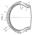
- Fig. 1 a first embodiment of the tire according to the invention, wherein numeral 1 is a pneumatic tire for the front wheel of the motorcycle (not shown), and numeral 2 a carcass comprised of two carcass plies 4, 6.
- numeral 1 is a pneumatic tire for the front wheel of the motorcycle (not shown)
- numeral 2 a carcass comprised of two carcass plies 4, 6.
- each of the carcass plies 4, 6 are embedded a plurality of organic fiber cords such as nylon cords so as to extend at a cord angle of 60-90° with respect to an equatorial plane E of the tire.
- the tire 1 comprises a belt 12 disposed on an outer periphery of the carcass 2 in a radial direction of the tire.
- the belt 12 is a spiral belt layer formed by spirally winding a continuous rubberized cord or a continuous ribbon-shaped body containing plural cords therein in a widthwise direction of the tire so as to extend the cord substantially in a circumferential direction of the tire.
- the cord is preferably used a high strength and high tenacity aramid fiber cord (Kevlar, trade name) or the like.
- a tread 14 is disposed on an outer periphery of the belt 12 in the radial direction and has so-called cap/base structure.
- the tread 14 is comprised of a cap rubber layer 16 and a base rubber layer 18 over a whole of the tread in a widthwise direction thereof.
- a Shore A hardness of the cap rubber layer 16 is made higher than that of the base rubber layer 18 and the difference of Shore A hardness between the cap rubber layer and the base rubber layer is set to be not less than 2°.
- the cap rubber layer 16 and the base rubber layer 18 satisfy a relation that a ratio B/(A+B) is within a range of 0.2 ⁇ 0.5 wherein A is a thickness of the cap rubber layer and B is a thickness of the base rubber layer.
- a crown portion of the carcass 2 is reinforced with the spiral belt layer 12, so that the high speed durability is excellent as compared with the conventional tire using a cross structure belt.
- the flexible structure of the spiral belt layer 12 is reinforced with the cap rubber layer 16 having a relatively high hardness.
- the cap rubber layer 16 ensures the shearing rigidity of the tread 14 at a state that the thickness of the tread is relatively thick as in a new tire. As a result, the high speed running stability at the new tire state and the handling nimbleness and response are excellent.
- the hardness of the cap rubber layer 16 is set to be higher than that of the base rubber layer 18, whereby it is possible to control the rising ratio of the shearing rigidity in the tread 14 as the wearing increases and hence it is possible to hold the change of the shearing rigidity or the change of the steering performance from new tire state to last worn state at a small level.
- the sufficient rigidity of the tread can be ensured, so that the occurrence of shimmy can be prevented as compared with the case that the whole of the tread is made of only rubber having a low hardness.
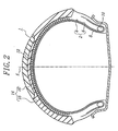
- Fig. 2 a second embodiment of the pneumatic tire for the front wheel of the motorcycle according to the invention.
- This tire is a modified embodiment of Fig. 1, wherein the cap rubber layer 16 is disposed in only a central portion of the tread in the widthwise direction of the tire. Even in this case, there can be obtained substantially the same effects as in the first embodiment.
- Fig. 3 is shown a third embodiment of the pneumatic tire for the front wheel of the motorcycle according to the invention, wherein numeral 20 is a pneumatic tire, numeral 22 a sidewall portion, numeral 24 a tread portion extending between a pair of the sidewall portions 22, numeral 26 a bead core, and numeral 28 a carcass toroidally extending between a pair of the bead cores 26.
- the carcass 28 is comprised of two rubberized plies each containing organic fiber cords arranged at a cord angle of 60-90° with respect to the equatorial plane of the tire.
- numeral 30 is a belt disposed on an outer periphery of the carcass 28 in the radial direction, which is a spiral belt layer formed by spirally winding a continuous rubberized cord or a continuous ribbon-shaped body containing plural cords therein in a widthwise direction of the tire so as to extend the cord substantially in a circumferential direction of the tire, and numeral 32 a reinforcing layer arranged inside the carcass 28 in the radial direction.
- the reinforcing layer 32 has a width corresponding to 20 ⁇ 120% of a width of the spiral belt layer 30. In the illustrated embodiment, the width of the reinforcing layer 32 is 110% of the width of the spiral belt layer 30.
- the bending rigidity of the tread under loading and the shearing rigidity in a region ranging from the surface of the tread 24 to the carcass 28 can be held at a high level by arranging the reinforcing layer 32, whereby it is possible to prevent the degradation of the steering performance inevitably caused when only the spiral belt layer is used instead of the cross structure belt in the conventional pneumatic tire.
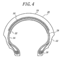
- Fig. 4 is a fourth embodiment of the pneumatic tire for the front wheel of the motorcycle according to the invention, wherein the reinforcing layer 32 is arranged on a surface of an innerliner 34 (or inner surface of the tire in the radial direction). Even in this tire, not only the bending rigidity of the tread but also the shearing rigidity between the tread surface and the carcass are held at a high level.
- Fig. 5 is a fifth embodiment of the pneumatic tire for the front wheel of the motorcycle according to the invention, wherein the reinforcing layer 32 is arranged inside the carcass 28 at a width L corresponding to 20 ⁇ 60% of the width L 1 of the spiral belt layer 30.
- the reinforcing layer 32 may be arranged on the surface of the innerliner 34 likewise the case of Fig. 4. Even in the case of using such a narrow-width reinforcing layer, it is possible to improve the steering performances, and particularly the grip feeling in the cornering and handling nimbleness are improved as compared with the case of using the wide-width reinforcing layer as shown in Figs. 3 and 4.
- the width L of the reinforcing layer is outside the range corresponding to 20-120% of the width L 1 of the spiral belt layer, the bending rigidity of the sidewall portion becomes too high and the steering performances are degraded.
- the width L is within a range of 20 ⁇ 60% of the width L 1 , the adequate rigidity of the tread is ensured, whereby it possible to obtain the balance among prevention of shimmy, steering stability, handling nimbleness and grip feeling in the cornering at a high level.
- the reinforcing layer is used a rubber sheet in the illustrated embodiment, but one or more rubberized cord layers may be used.
- Fig. 6 a sixth embodiment of the pneumatic tire for the front wheel of the motorcycle according to the invention, wherein numeral 40 is a sidewall portion, numeral 42 a tread portion extending between the pair of the sidewall portions 40, and numeral 44 a bead portion located inward from the sidewall portion 40 in the radial direction.
- Numeral 46 is a carcass comprised of two rubberized carcass plies 48, 50 each containing organic fiber cords such as nylon-6,6 cords arranged at a cord angle of 60-90° with respect to an equatorial plane E of the tire and reinforcing both the sidewall portions 40 and the tread portion 40.
- Each end portion of the carcass plies 48, 50 is wound around a bead core 52 embedded in the bead portion 44 from an inside of the tire toward an outside thereof.
- Numeral 54 is a belt disposed on an outer periphery of a crown portion of the carcass 46, which is a spiral belt layer formed by spirally winding a continuous rubberized cord or a continuous ribbon-shaped body containing plural cords therein in a widthwise direction of the tire so as to extend the cord substantially in a circumferential direction of the tire.
- the cord is made of an organic fiber having a high modulus of elasticity such as high modulus polyester fiber, polyvinyl alcohol fiber, rayon fiber, aromatic polyamide fiber or the like and has a modulus of elasticity of not less than 600 kgf/cm 2 .
- the belt 54 can develop a high rigidity in the radial direction of the tire because the cord extends in the circumferential direction of the tire.
- the bead core 52 embedded in the bead portion 44 for ensuring the fitting of the tire to a rim is constituted with a helically wound laminate of a single steel wire having a polygonal shape at a section of the bead core in the radial direction.
- Figs. 7a to 7e concretely show various sectional shapes of the bead core 52, respectively.
- the bead core 52 shown in Fig. 7a is a three-layer laminate structure formed by helically winding the single steel wire three times in the widthwise direction of the bead core, and then helically winding on an outer periphery thereof three times, and further helically winding on an outer periphery thereof three times and has a sectional profile of approximately a square.
- the bead core 52 shown in Fig. 7b has a sectional profile of approximately a square formed by repeating the helical winding of four times over four stages.
- the bead core 52 shown in Fig. 7d has a sectional profile of approximately a hexagon formed by repeating the helical windings of two times, three times and two times from an inner peripheral side of the tire in the radial direction over three stages.
- the bead core 52 shown in Fig. 7d has a sectional profile of approximately a hexagon formed by repeating the helical windings of three times, four times and three times from an inner peripheral side of the tire in the radial direction over three stages.
- the bead core 52 shown in Fig. 7e has a sectional profile of approximately a hexagon formed by repeating the helical windings of two times, three times, four times and three times from an inner peripheral side of the tire in the radial direction over four stages.
- the sectional profile of the bead core 52 may be pentagonal.
- the single steel wire is helically wound and laminated in such a manner that a side of the polygon form the base when the bead core 52 is embedded in the bead portion 44 for increasing air tightness between a bead base of the bead portion and a bead seat of the rim and improving the resistance to rim slippage and realizing the strong connection between the bead portion and the rim.
- the high rigidity is obtained by the bead core 52 in the widthwise direction at the radial section and in the torsional direction around the axial line of the bead core, whereby the bending rigidity of the tread is advantageously increased at the section in the widthwise direction of the tire. Therefore, when such a tire is used for the front wheel of the motorcycle, the steering stability can largely be improved without damaging the properties inherent to this tire.
- Fig. 8 a seventh embodiment of the pneumatic tire for the front wheel of the motorcycle according to the invention, wherein numeral 60 is a sidewall portion, numeral 62 a tread extending between a pair of the sidewall portions 60, numeral 64 a bead core, numeral 66 a carcass ply containing organic fiber cords arranged at a cord angle of 60-90° with respect to an equatorial plane of the tire and wound around the bead core 64 form an inside of the tire toward an outside thereof to form a tumup portion.
- numeral 60 is a sidewall portion
- numeral 62 a tread extending between a pair of the sidewall portions 60
- numeral 64 a bead core
- numeral 66 a carcass ply containing organic fiber cords arranged at a cord angle of 60-90° with respect to an equatorial plane of the tire and wound around the bead core 64 form an inside of the tire toward an outside thereof to form a tumup portion.
- Numeral 68 is a belt disposed on an outer periphery of a crown portion of the carcass ply 66, which is a spiral belt layer formed by spirally winding a continuous rubberized cord or a continuous ribbon-shaped body containing plural cords therein in a widthwise direction of the tire so as to extend the cord substantially in a circumferential direction of the tire.
- Numeral 70 is a bead filler made of rubber having a Shore hardness of 60-99° and arranged at the outside of the turnup portion of the carcass ply 66.
- the bead filler 70 is located at a position of creating a largest bending in the occurrence of lateral force under a load, whereby the bending rigidity of the sidewall portion is improved to ensure shearing rigidity between the tread and the spiral belt layer for the prevention of shimmy and hence the steering performance is improved.
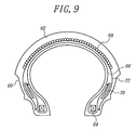
- Fig. 9 is shown an eighth embodiment of the pneumatic tire for a front wheel of a motorcycle according to the invention, which has the same basic structure as in Fig. 8 except that a down ply 72 is arranged at the outside of the carcass ply 66 and the bead filler 70 is arranged between the tumup portion of the carcass ply 66 and the down ply 72.
- the bead filler is located at a position relatively near to a neutral axis of the bending of the sidewall portion, whereby a middle rigidity in the lateral direction is obtained.
- Fig. 10 a ninth embodiment of the pneumatic tire for a front wheel of a motorcycle according to the invention, which has the same basic structure as in Fig. 8 except that a down ply 72 is arranged at the outside of the carcass ply 66 and the bead filler 70 is arranged at the outside of the down ply 72.
- the bead filler is located at a position most apart from the neutral axis of the bending of the sidewall portion, whereby a highest rigidity in the lateral direction is obtained.
- Example 1 Conventional Examples 1-2
- Example 1 There are provided three tires of Example 1 and Conventional Examples 1 and 2 for use in a front wheel of a motorcycle, respectively.
- the tread has a cap/base structure shown in Fig. 1.
- the tread is made of a single rubber.
- the hardness of rubber constituting the tread and the like is shown in Table 1.
- all of these tires have two carcass plies containing nylon cords therein and a spiral belt layer containing Kevlar cords therein.
- Each of these tires is mounted onto a front wheel of a motorcycle (HONDA CBR1100XX) and actually run on a test circuit course by a professional rider, during which the high-speed straight running stability, shimmy resistance, handling nimbleness/response and over-steering of handle at a low speed are evaluated to obtain results as shown in Table 1.
- Each property is represented by an index on the basis that the tire of Conventional Example 1 is 100, wherein the larger the index value, the better the property.
- over-steering of handle means a phenomenon that when the vehicle body of the motorcycle is slightly tilted, the handle tends to further over-steer inward in the tilting direction owing to the peculiarity of tire/machine. As the over-steering becomes large, it is difficult to steer the handle by the rider.
- two pneumatic tires having a tire size of 120/70ZR17 and a basic structure shown in Fig. 3 comprising a carcass of two nylon cord plies and a spiral belt layer of Kevlar cord with a belt width of 140 mm, wherein the tire of Example 2 is provided with a rubber sheet located inside an innermost carcass ply and having a thickness of 0.5 mm and a width of 70 mm as a reinforcing layer, and the tire of Example 3 is provided with a rubberized nylon cord layer of 840 d located inside the innermost carcass ply as a reinforcing layer.
- Each of these tires is mounted onto a front wheel of a motorcycle (HONDA CB1100XX) and actually run at a high speed (250 km/h), during which the straight running stability, slummy resistance, handling nimbleness/response, cornering force/gripping force and ride comfort are measured together with a tire of Comparative Example 1 having no reinforcing layer, a tire of Comparative Example 2 having the rubber sheet disposed between the belt and the carcass ply as a reinforcing layer and a tire of Comparative Example 3 having the rubber sheet disposed between the carcass plies as a reinforcing layer.
- the tire of Comparative Example 2 has the straight running stability of 90, shimmy resistance of 130, handling nimbleness/response of 110, cornering force/gripping force of 90 and ride comfort of about 85
- the tire of Comparative Example 3 has the straight running stability of 80, shimmy resistance of 120, handling nimbleness/response of 100, cornering force/gripping force of 80 and ride comfort of about 90.
- the tire of Example 2 has the straight running stability of 110, shimmy resistance of 110, handling nimbleness/response of 110, cornering force/gripping force of 100 and ride comfort of about 100
- the tire of Example 3 has the straight running stability of 120, shimmy resistance of 120, handling nimbleness/response of 120, cornering force/gripping force of 95 and ride comfort of about 90.
- the deformation of the tire in both lateral and torsional directions becomes small as compared with those of Comparative Examples 1-3, and the absorption of wobbling (the wobbling is an oscillation of not more than 10 Hz in a whole of a frame and a handle produced at a high speed zone and the speed zone generating such an oscillation differs in accordance with the kind of the motorcycle and the condition (not less than 150 km/h in CB1100XX)) is improved, which is confirmed to contribute to the improvement of the high-speed straight running stability.
- the wobbling is an oscillation of not more than 10 Hz in a whole of a frame and a handle produced at a high speed zone and the speed zone generating such an oscillation differs in accordance with the kind of the motorcycle and the condition (not less than 150 km/h in CB1100XX)
- the tire deformation in the lateral and torsional directions is small and the amplitude in disturbance input tends to be small.
- the reaction of the vehicle body is improved in the steering of the handle.
- the cornering force/gripping force the occurrence of lateral force becomes large and the falling-down inherent to the motorcycle in the cornering is decreased and the cornering force is improved.
- the thrusting in the riding on projection becomes somewhat sharp in the tires according to the invention, but since the tread portion is soft, the absolute level of the ride comfort is sufficiently put into practical use.
- the tire of Example 4 uses a bead core shown in Fig. 7b, and the tire of Example 5 uses a bead core shown in Fig. 7c, and the tire of Example 6 uses a bead core shown in Fig. 7d.
- the tire of Conventional Example 3 uses a bead core formed by helically winding four steel wires arranged side by side in four laminated layers. The other structure of the tire is the same in all of the tires.
- a pneumatic tires (Example 7) having a tire size of 120/70ZR17 and a structure shown in Fig. 8, wherein a carcass is comprised of two plies each containing nylon cords arranged at a cord angle of 80° with respect to an equatorial plane of the tire and wound around a bead core from an inside of the tire toward an outside thereof and a belt is constituted with a spiral belt layer of an aromatic polyamide fiber cord and a bead filler having a Shore A hardness of 95° is arranged at an outside of a turnup portion of an outermost carcass ply.
- This tire is mounted onto a front wheel of a motorcycle (HONDA CB 1100XX) and actually run at a high speed (250 km/h), during which the straight running stability, shimmy resistance, handling nimbleness/response, cornering force/gripping force and ride comfort are measured by a professional rider together with a first comparative tire having the bead filler arranged between the carcass ply and the turnup portion thereof (Comparative Example 4) and a second comparative tire having no bead filler (Comparative Example 5).
- the tire of Comparative Example 1 has the straight running stability of 130, shimmy resistance of 130, handling nimbleness/response of 130, cornering force/gripping force of 120 and ride comfort of about 90, while the tire of Example 7 has the straight running stability of 140, shimmy resistance of 140, handling nimbleness/response of 140, cornering force/gripping force of 130 and ride comfort of 85.
- the deformation in both lateral and torsional directions tends to become small and the absorption of wobbling (the wobbling is an oscillation of not more than 10 Hz in a whole of a frame and a handle produced at a high speed zone) is improved without decreasing the lateral force generated.
- the shimmy resistance the tire deformation in the lateral and torsional directions is small and the amplitude in disturbance input tends to be mitigated.
- the handling nimbleness/response the reaction of the vehicle body is improved in the steering of the handle.
- the cornering force/gripping force the occurrence of lateral force becomes large and the falling-down inherent to the motorcycle in the cornering is decreased and the cornering force is improved.
- the thrusting in the riding on projection becomes somewhat sharp in the tires according to the invention as compared with the comparative tires, but since the tread portion is soft, the absolute level of the ride comfort is sufficiently put into practiceal use.
- the straight running stability is sufficently enhanced, and also the occurrence of shimmy can effectively be prevented when the tire is used in the front wheel of the motorcycle.
- the tires of the various aspects of the invention preferably have a tread width which is wider than the maximum distance between the tire sidewalls.
Applications Claiming Priority (9)
| Application Number | Priority Date | Filing Date | Title |
|---|---|---|---|
| JP10335160A JP2000158920A (ja) | 1998-11-26 | 1998-11-26 | 二輪車用前輪タイヤ |
| JP33516098 | 1998-11-26 | ||
| JP35483898 | 1998-12-14 | ||
| JP35483898A JP4191297B2 (ja) | 1998-12-14 | 1998-12-14 | 自動二輪車用空気入りタイヤ |
| JP35559698A JP4242959B2 (ja) | 1998-12-15 | 1998-12-15 | 自動二輪車用空気入りタイヤ |
| JP35612698A JP4181260B2 (ja) | 1998-12-15 | 1998-12-15 | 二輪車用空気入りタイヤ |
| JP35559698 | 1998-12-15 | ||
| JP35612698 | 1998-12-15 | ||
| EP99309208A EP1004460A3 (de) | 1998-11-26 | 1999-11-18 | Reifen für Vorderrad eines Motorrads |
Related Parent Applications (1)
| Application Number | Title | Priority Date | Filing Date |
|---|---|---|---|
| EP99309208A Division EP1004460A3 (de) | 1998-11-26 | 1999-11-18 | Reifen für Vorderrad eines Motorrads |
Publications (1)
| Publication Number | Publication Date |
|---|---|
| EP1541378A1 true EP1541378A1 (de) | 2005-06-15 |
Family
ID=27480532
Family Applications (2)
| Application Number | Title | Priority Date | Filing Date |
|---|---|---|---|
| EP99309208A Withdrawn EP1004460A3 (de) | 1998-11-26 | 1999-11-18 | Reifen für Vorderrad eines Motorrads |
| EP05001325A Withdrawn EP1541378A1 (de) | 1998-11-26 | 1999-11-18 | Reifen für Vorderrad eines Motorrads |
Family Applications Before (1)
| Application Number | Title | Priority Date | Filing Date |
|---|---|---|---|
| EP99309208A Withdrawn EP1004460A3 (de) | 1998-11-26 | 1999-11-18 | Reifen für Vorderrad eines Motorrads |
Country Status (2)
| Country | Link |
|---|---|
| US (2) | US6286575B1 (de) |
| EP (2) | EP1004460A3 (de) |
Cited By (2)
| Publication number | Priority date | Publication date | Assignee | Title |
|---|---|---|---|---|
| EP2184187A1 (de) * | 2007-08-27 | 2010-05-12 | Bridgestone Corporation | Luftreifen für ein zweirädriges fahrzeug |
| US20180154706A1 (en) * | 2016-12-07 | 2018-06-07 | Sumitomo Rubber Industries, Ltd. | Pneumatic tire for a motorcycle |
Families Citing this family (24)
| Publication number | Priority date | Publication date | Assignee | Title |
|---|---|---|---|---|
| GB9928630D0 (en) * | 1999-12-04 | 2000-02-02 | Dunlop Tyres Ltd | Motor-cycle radial tyre |
| JP2002019428A (ja) * | 2000-07-06 | 2002-01-23 | Bridgestone Corp | ビードコアーおよび該ビードコアーを備えた空気入りタイヤ |
| WO2002094585A1 (fr) * | 2001-05-21 | 2002-11-28 | Societe De Technologie Michelin | Pneumatique comportant un protege jante renforce |
| EP1318030A1 (de) * | 2001-12-04 | 2003-06-11 | Société de Technologie Michelin | Reifen mit verstärktem Verankerungsbereich |
| JP4109468B2 (ja) * | 2002-03-05 | 2008-07-02 | 住友ゴム工業株式会社 | 自動二輪車用ラジアルタイヤ |
| JP4350622B2 (ja) * | 2004-09-07 | 2009-10-21 | 住友ゴム工業株式会社 | 空気入りタイヤ |
| JP4264053B2 (ja) * | 2004-12-01 | 2009-05-13 | 住友ゴム工業株式会社 | 空気入りタイヤの製造方法 |
| FR2886215A1 (fr) * | 2005-05-24 | 2006-12-01 | Michelin Soc Tech | Pneumatique pour deux roues |
| US20070017617A1 (en) * | 2005-07-22 | 2007-01-25 | Lafrique Michel M | Tire with tread of cap/semibase construction |
| WO2007055322A1 (ja) * | 2005-11-11 | 2007-05-18 | Bridgestone Corporation | 二輪車用空気入りタイヤ |
| JP4566903B2 (ja) * | 2005-12-20 | 2010-10-20 | 住友ゴム工業株式会社 | 自動二輪車用タイヤ |
| JP4744392B2 (ja) * | 2006-08-11 | 2011-08-10 | 株式会社ブリヂストン | 自動二輪車用空気入りラジアルタイヤ |
| US20080216930A1 (en) * | 2007-03-05 | 2008-09-11 | Christopher John Valentine | Tyre with rubber tread which contains internal circumferential rubber stabilizer bars |
| US20090107609A1 (en) * | 2007-10-31 | 2009-04-30 | Walter Kevin Westgate | High Extensible Cut-Resistant Barrier |
| EP2181864B1 (de) * | 2008-11-04 | 2011-05-18 | Sumitomo Rubber Industries, Ltd. | Luftreifen für ein Motorrad |
| FR2957020B1 (fr) * | 2010-03-05 | 2012-03-16 | Michelin Soc Tech | Pneumatique pour vehicules comportant une bande de roulement constituee de plusieurs melanges et une armature de carcasse radiale formee d'au moins deux couches. |
| US20130032266A1 (en) * | 2011-08-03 | 2013-02-07 | Sujith Nair | Rubber reinforced article with voided fibers |
| US9283817B2 (en) | 2011-11-22 | 2016-03-15 | The Goodyear Tire & Rubber Company | Stiffness enhanced tread |
| US20130153082A1 (en) * | 2011-12-14 | 2013-06-20 | International Business Machines Corporation | Variable friction tires |
| JP5548183B2 (ja) * | 2011-12-29 | 2014-07-16 | 住友ゴム工業株式会社 | 自動二輪車用タイヤ |
| FR3028450B1 (fr) * | 2014-11-18 | 2016-11-18 | Michelin & Cie | Armature de carcasse de pneumatique pour moto |
| JP6880768B2 (ja) * | 2017-01-23 | 2021-06-02 | 横浜ゴム株式会社 | 空気入りタイヤ |
| JP7081207B2 (ja) * | 2018-02-27 | 2022-06-07 | 住友ゴム工業株式会社 | 二輪車用タイヤ |
| JP7056227B2 (ja) * | 2018-02-27 | 2022-04-19 | 住友ゴム工業株式会社 | 二輪車用タイヤ |
Citations (2)
| Publication number | Priority date | Publication date | Assignee | Title |
|---|---|---|---|---|
| US3911987A (en) * | 1972-11-13 | 1975-10-14 | Bridgestone Tire Co Ltd | Pneumatic safety tire for motorcycles |
| EP0522468A1 (de) * | 1991-07-11 | 1993-01-13 | The Goodyear Tire & Rubber Company | Reifenaufbau, der die Innenschicht un den Wulstschutz verbindet |
Family Cites Families (10)
| Publication number | Priority date | Publication date | Assignee | Title |
|---|---|---|---|---|
| JPS5973307A (ja) * | 1982-10-18 | 1984-04-25 | Bridgestone Corp | 二輪車用空気入りベルテツドタイヤ対 |
| JPS59199305A (ja) * | 1983-04-25 | 1984-11-12 | Mitsuboshi Belting Ltd | 自転車タイヤ |
| JPS6056603A (ja) * | 1983-09-09 | 1985-04-02 | Bridgestone Corp | 外乱吸収性にすぐれるモ−タ−サイクル用タイヤ |
| JPH07172117A (ja) * | 1993-04-16 | 1995-07-11 | Sumitomo Rubber Ind Ltd | 自動二輪車用ラジアルタイヤ |
| JP2799322B2 (ja) * | 1993-06-07 | 1998-09-17 | 住友ゴム工業株式会社 | 自動二輪車用空気入りタイヤ |
| JPH0719506A (ja) | 1993-06-28 | 1995-01-20 | Fuji Kankyo Syst Kk | 伝熱パネルの構造 |
| JPH07195906A (ja) * | 1993-12-29 | 1995-08-01 | Sumitomo Rubber Ind Ltd | 自動二輪車用タイヤ |
| IT1277400B1 (it) * | 1995-08-01 | 1997-11-10 | Pirelli | Pneumatico ad elevata curvatura trasversale particolarmente per veicolo a due ruote |
| JPH09175123A (ja) * | 1995-12-26 | 1997-07-08 | Bridgestone Corp | フリッパーを備えたモーターサイクル用空気入りラジアルタイヤ |
| JP2000158910A (ja) | 1998-11-30 | 2000-06-13 | Bridgestone Corp | 自動二輪車用空気入りタイヤ |
-
1999
- 1999-11-18 EP EP99309208A patent/EP1004460A3/de not_active Withdrawn
- 1999-11-18 EP EP05001325A patent/EP1541378A1/de not_active Withdrawn
- 1999-11-24 US US09/448,426 patent/US6286575B1/en not_active Expired - Lifetime
-
2001
- 2001-07-20 US US09/908,795 patent/US20020000276A1/en not_active Abandoned
Patent Citations (2)
| Publication number | Priority date | Publication date | Assignee | Title |
|---|---|---|---|---|
| US3911987A (en) * | 1972-11-13 | 1975-10-14 | Bridgestone Tire Co Ltd | Pneumatic safety tire for motorcycles |
| EP0522468A1 (de) * | 1991-07-11 | 1993-01-13 | The Goodyear Tire & Rubber Company | Reifenaufbau, der die Innenschicht un den Wulstschutz verbindet |
Cited By (6)
| Publication number | Priority date | Publication date | Assignee | Title |
|---|---|---|---|---|
| EP2184187A1 (de) * | 2007-08-27 | 2010-05-12 | Bridgestone Corporation | Luftreifen für ein zweirädriges fahrzeug |
| EP2184187A4 (de) * | 2007-08-27 | 2011-03-23 | Bridgestone Corp | Luftreifen für ein zweirädriges fahrzeug |
| CN101808834B (zh) * | 2007-08-27 | 2012-02-15 | 株式会社普利司通 | 两轮车用充气轮胎 |
| US20180154706A1 (en) * | 2016-12-07 | 2018-06-07 | Sumitomo Rubber Industries, Ltd. | Pneumatic tire for a motorcycle |
| EP3332953A1 (de) * | 2016-12-07 | 2018-06-13 | Sumitomo Rubber Industries, Ltd. | Luftreifen für ein motorrad |
| US10974552B2 (en) * | 2016-12-07 | 2021-04-13 | Sumitomo Rubber Industries, Ltd. | Pneumatic tire for a motorcycle |
Also Published As
| Publication number | Publication date |
|---|---|
| US6286575B1 (en) | 2001-09-11 |
| US20020000276A1 (en) | 2002-01-03 |
| EP1004460A3 (de) | 2001-11-14 |
| EP1004460A2 (de) | 2000-05-31 |
Similar Documents
| Publication | Publication Date | Title |
|---|---|---|
| US6286575B1 (en) | Pneumatic tire for front wheel of motorcycle | |
| EP0808730B1 (de) | Paar von Reifen mit hoher Querkrümmung für Zweiradfahrzeuge | |
| EP1759886B1 (de) | Radial-luftreifen für zweirädrige fahrzeuge | |
| JP4558733B2 (ja) | 二輪自動車用タイヤ | |
| JP5063304B2 (ja) | 自動二輪車用空気入りタイヤ | |
| JP4040893B2 (ja) | スクーター用空気入りラジアルタイヤおよびスクーター | |
| JPH0532242B2 (de) | ||
| EP1149714B1 (de) | Verfahren zur Montage eines radialen Fahrzeugreifens | |
| JP2007125988A (ja) | 二輪車用空気入りタイヤ | |
| JP2010247744A (ja) | 自動二輪車用空気入りタイヤ | |
| JP4677116B2 (ja) | 二輪車用ラジアルタイヤ | |
| KR100572048B1 (ko) | 높은 횡곡률 계수를 갖는, 특히 2륜 차량용 타이어 | |
| JP4325906B2 (ja) | 自動二輪車用空気入りタイヤ | |
| JP2008162355A (ja) | 自動二輪車用タイヤ | |
| JP4181262B2 (ja) | 二輪車用空気入りタイヤ | |
| JP4540587B2 (ja) | 二輪車用空気入りタイヤ | |
| JP4349607B2 (ja) | 自動二輪車用空気入りタイヤ | |
| JP2006298082A (ja) | 二輪車用空気入りタイヤ | |
| US6695025B1 (en) | Runflat tire construction with ply cords having a variable modulus of elasticity | |
| JP4133210B2 (ja) | 二輪車用タイヤ | |
| JP2007186123A (ja) | 空気入りタイヤ | |
| JP3843181B2 (ja) | 空気入りタイヤ | |
| JP6133066B2 (ja) | 空気入りタイヤ | |
| JPH08113008A (ja) | 自動二輪車用空気入りバイアス・タイヤ | |
| JP4855746B2 (ja) | 空気入りタイヤ及び空気入りタイヤの製造方法 |
Legal Events
| Date | Code | Title | Description |
|---|---|---|---|
| PUAI | Public reference made under article 153(3) epc to a published international application that has entered the european phase |
Free format text: ORIGINAL CODE: 0009012 |
|
| 17P | Request for examination filed |
Effective date: 20050208 |
|
| AC | Divisional application: reference to earlier application |
Ref document number: 1004460 Country of ref document: EP Kind code of ref document: P |
|
| AK | Designated contracting states |
Kind code of ref document: A1 Designated state(s): DE ES FR GB IT |
|
| AKX | Designation fees paid |
Designated state(s): DE ES FR GB IT |
|
| STAA | Information on the status of an ep patent application or granted ep patent |
Free format text: STATUS: THE APPLICATION IS DEEMED TO BE WITHDRAWN |
|
| 18D | Application deemed to be withdrawn |
Effective date: 20061013 |