EP1537021B1 - Verpackungsmaschine mit einer verfahreinheit - Google Patents
Verpackungsmaschine mit einer verfahreinheit Download PDFInfo
- Publication number
- EP1537021B1 EP1537021B1 EP03747938A EP03747938A EP1537021B1 EP 1537021 B1 EP1537021 B1 EP 1537021B1 EP 03747938 A EP03747938 A EP 03747938A EP 03747938 A EP03747938 A EP 03747938A EP 1537021 B1 EP1537021 B1 EP 1537021B1
- Authority
- EP
- European Patent Office
- Prior art keywords
- packaging machine
- machine according
- packaging
- cable
- travelling unit
- Prior art date
- Legal status (The legal status is an assumption and is not a legal conclusion. Google has not performed a legal analysis and makes no representation as to the accuracy of the status listed.)
- Expired - Lifetime
Links
- 238000004806 packaging method and process Methods 0.000 title claims abstract description 51
- 238000006073 displacement reaction Methods 0.000 title abstract description 5
- 238000007789 sealing Methods 0.000 claims description 3
- 238000003856 thermoforming Methods 0.000 claims description 3
- 239000004033 plastic Substances 0.000 description 2
- 239000011888 foil Substances 0.000 description 1
- 239000012785 packaging film Substances 0.000 description 1
- 229920006280 packaging film Polymers 0.000 description 1
Images

Classifications
-
- B—PERFORMING OPERATIONS; TRANSPORTING
- B65—CONVEYING; PACKING; STORING; HANDLING THIN OR FILAMENTARY MATERIAL
- B65B—MACHINES, APPARATUS OR DEVICES FOR, OR METHODS OF, PACKAGING ARTICLES OR MATERIALS; UNPACKING
- B65B9/00—Enclosing successive articles, or quantities of material, e.g. liquids or semiliquids, in flat, folded, or tubular webs of flexible sheet material; Subdividing filled flexible tubes to form packages
- B65B9/02—Enclosing successive articles, or quantities of material between opposed webs
- B65B9/04—Enclosing successive articles, or quantities of material between opposed webs one or both webs being formed with pockets for the reception of the articles, or of the quantities of material
-
- Y—GENERAL TAGGING OF NEW TECHNOLOGICAL DEVELOPMENTS; GENERAL TAGGING OF CROSS-SECTIONAL TECHNOLOGIES SPANNING OVER SEVERAL SECTIONS OF THE IPC; TECHNICAL SUBJECTS COVERED BY FORMER USPC CROSS-REFERENCE ART COLLECTIONS [XRACs] AND DIGESTS
- Y10—TECHNICAL SUBJECTS COVERED BY FORMER USPC
- Y10T—TECHNICAL SUBJECTS COVERED BY FORMER US CLASSIFICATION
- Y10T74/00—Machine element or mechanism
- Y10T74/18—Mechanical movements
- Y10T74/18056—Rotary to or from reciprocating or oscillating
Definitions
- the present invention relates to a packaging machine with a track, wherein a moving packaged goods support is arranged on the moving unit.
- Packaged goods such as food
- plastic packaging usually have a packaging tray in which the packaged goods is and a lid film on.
- the lidding foil is sealed to the packaging tray.
- thermoformers as known, for example, from US Pat. No. 3,808,772, in which a plurality of packaging trays are deep-drawn from a so-called lower film. After deep drawing, the respective packaging tray is filled with a packaged product and then sealed with a lidding film. As a final step, the finished packages are separated with a length and cross cutter or a complete cut.
- the present invention is therefore an object of the invention to provide a packaging machine available, the o. G. Meets demands.
- a packaging machine is any known to the expert thermoforming packaging machine, in which from a so-called lower film a variety of packaging trays are deep-drawn, which are filled after deep drawing with a packaged goods, such as food, and then sealed with a lidding film and finally cut apart.
- This packaging machine according to the invention has a track.
- a moving part according to the invention is, for example, a punch, a sealing station and / or a cross cutter, which is displaceable along the machine in or against the transport direction of the film (s) at least in a certain range.
- the trajectory can be arranged in any section of the packaging machine with respect to the transport direction of the film after the thermoforming station.
- the displacement of the moving part takes place with a motor in or against the direction of the product flow.
- At least one accompanying packaged goods supports are arranged on the trackside.
- this Packgutunterstützung is a rope, particularly preferably a wire rope.
- the Packgutunterstützung a thin elastic band of any width. The rope and / or the band runs below the lower film and parallel to the direction of displacement of the moving unit and is arranged between two packages, so that the lower film, in which the packages are formed, does not sag.
- each cable or band has a first and a second end, which are each removably arranged on the track.
- cables or belts are arranged one behind the other transversely to the running direction of the lower film.
- the packaging machine according to the invention has at least four rollers, with which the rope and / or the band is deflected. These rollers are preferably arranged by means of male connectors on the frame of the packaging machine.
- the embodiment with the headers has the advantage that the packaging machine according to the invention can be easily and quickly converted to another form of packaging or packaging size. The position of the rollers can be adapted to the respective requirements.
- the rope and / or the band can be tensioned with a means.
- this means is arranged on the track unit.
- the respective loads of the cables and / or belts can be taken into account so that the film they support does not sag.
- the rope or band should not be too tight.
- each side or band is associated with a respective clamping means.
- the track unit also has at least one connector strip on which the cables and / or bands are each fastened individually and then tensioned individually.
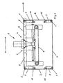
- FIG. 1 a part of the track unit 1 is shown.
- the moving unit 1 is part of a packaging machine which has a deep-drawing, a filling, a sealing and a separating station.
- the trajectory can take over one of the last three functions.
- a cross-cutting station is a Packgutunterstützung 2, a wire rope 2, arranged.
- the cable 2 is deflected by means of the four rollers 6 and is detachably connected with its ends 3, 4 with the track 1.
- Through the rope 2 are the Packaging troughs 8, which move in the direction shown by the arrow, so supported that the film from which the respective packaging troughs is formed, neither longitudinal nor transverse to the direction of sag.
- a plurality of packaging trays 8 can be arranged one behind the other and, accordingly, a plurality of packaged goods supports 2 are arranged one behind the other.
- the rollers 6 are mounted on connectors 7, which are flexibly plugged onto the transverse strips 10 and screwed there. Through the use of connector strips 7, the packaging machine according to the invention can be flexibly adjusted to the respective packaging form or packaging size.
- the movement unit 1 is driven by means of the toothed belt 9 and a motor, not shown, and can be moved along the direction indicated by the double arrow. Based on the running direction of the film, conventional packaged goods supports are located in front of and behind the moving unit.
- the length of the cables 2 can be adapted to the length of the track.
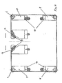
- FIG. 2 shows a plan view of the moving part according to FIG. 1, wherein the upper part of the cross cutting station and the packaging film with the packaging troughs 8 are not shown. From this view, it is clear that transverse to the direction of the machine, which is represented by the arrow, two Packgutunterstweilungen 2 are arranged one behind the other. Each cable 2 is provided with a means 5 (not shown in this view) with which the tension of the respective cable can be adjusted individually. The individual adjustment of the tension of the respective rope has the advantage that the tension of the rope can be adapted to the respective local requirements. The tension of the ropes in the middle of the packaging machine will be higher than the tension of the ropes in the edge region of the packaging machine. In the present case the tension of both ropes is the same. Furthermore, it can be seen from this view that the moving unit 1 is displaceable on the rods 11 along the indicated double arrow in the machine direction.
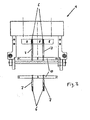
- FIG. 3 shows a front view of the moving unit according to FIG. From this view, it can be clearly seen how the ropes 2 and the rollers 6 Support the packaging trays 8 so that they sag neither longitudinally nor transversely to the machine direction.
- FIG. 4 shows a section through the moving part according to FIG. From this view it can be seen that the ends 3 and 4 of the cable 2 are detachably arranged on the track 1 and can be tensioned by means of the screws 5.
- each cable 2 at least one tensioning means 5 and four rollers 6 are associated with the associated plug-in strips 7.
- a screw is sufficient for tensioning the cables.
- the present embodiment has the advantage that the connection between the cable 2 and track 1 can be made faster and released again.
Landscapes
- Engineering & Computer Science (AREA)
- Mechanical Engineering (AREA)
- Auxiliary Devices For And Details Of Packaging Control (AREA)
- Containers And Plastic Fillers For Packaging (AREA)
- Basic Packing Technique (AREA)
- Supplying Of Containers To The Packaging Station (AREA)
Description
- Die vorliegende Erfindung betrifft eine Verpackungsmaschine mit einer Verfahreinheit, wobei an der Verfahreinheit eine mitlaufende Packgutunterstützung angeordnet ist.
- Packungsgüter, beispielsweise Lebensmittel, werden dem Verbraucher heutzutage immer öfter in Kunststoffverpackungen zum Kaufangeboten. Diese Kunststoffverpackungen weisen in der Regel eine Verpackungsmulde, in der sich das Verpackungsgut befindet und eine Deckelfolie auf. Die Deckelfolie ist an die Verpackungsmulde gesiegelt.
- Derartige Verpackungen werden oftmals auf Verpackungsmaschinen, sogenannten Thermoformern, wie sie beispielsweise aus der US 3,808, 772 bekannt sind hergestellt, bei denen aus einer sogenannten Unterfolie eine Vielzahl von Verpackungsmulden tiefgezogen werden. Nach dem Tiefziehen wird die jeweilige Verpackungsmulde mit einem Verpackungsgut befüllt und sodann mit einer Deckelfolie gesiegelt. Als letzten Schritt werden die fertigen Verpackungen mit einem Längs- und Querschneider oder durch einen Komplettschnitt voneinander getrennt.
- Derartige Verpackungsmaschinen müssen heutzutage immer flexibler und immer schneller auf die jeweils vom Kunden gewünschte Verpackungsart bzw. Verpackungsgröße einstellbar sein. Dadurch bedingt müssen eine entsprechende Anzahl an Schneideinrichtungen auf der Maschine bereitgehalten werden.
- Der vorliegenden Erfindung liegt deshalb die Aufgabe zugrunde, eine Verpackungsmaschine zur Verfügung zu stellen, die den o. g. Forderungen gerecht wird.
- Diese Aufgabe wird erfindungsgemäß durch eine Verpackungsmaschine gemäß Patentanspruch 1 gelöst.
- Eine Verpackungsmaschine im Sinne der Erfindung ist jede beliebige dem Fachmann geläufige Tiefziehverpackungsmaschine, bei der aus einer sogenannten Unterfolie eine Vielzahl von Verpackungsmulden tiefgezogen werden, die nach dem Tiefziehen mit einem Verpackungsgut, beispielsweise Lebensmitteln, befüllt und sodann mit einer Deckelfolie gesiegelt und abschließend auseinander geschnitten werden.
- Diese Verpackungsmaschine weist erfindungsgemäß eine Verfahreinheit auf. Eine Verfahreinheit im Sinne der Erfindung ist beispielsweise eine Stanze, eine Siegelstation und/oder ein Querschneider, die entlang der Maschine in bzw. gegen die Transportrichtung der Folie(n) zumindest in einem gewissen Bereich verschiebbar ist. Die Verfahreinheit kann in einem beliebigen Abschnitt der Verpackungsmaschine jedoch bezogen auf die Transportrichtung der Folie nach der Tiefziehstation angeordnet sein.
- Vorzugsweise erfolgt das Verschieben der Verfahreinheit mit einem Motor in oder gegen die Richtung des Produktflusses.
- Ebenfalls erfindungsgemäß sind an der Verfahreinheit indestens eine mitlaufende Packgutunterstützungen angeordnet. Vorzugsweise ist diese Packgutunterstützung ein Seil, besonders bevorzugt ein Drahtseil. Ebenfalls bevorzugt ist die Packgutunterstützung ein dünnes elastisches Band beliebiger Breite. Das Seil und/oder das Band verläuft unterhalb der Unterfolie sowie parallel zu der Verschieberichtung der Verfahreinheit und ist zwischen zwei Verpackungen angeordnet, so daß die Unterfolie, in die die Verpackungen eingeformt sind, nicht durchhängt.
- Vorzugsweise weist jedes Seil bzw. Band ein erstes und ein zweites Ende auf, die jeweils an der Verfahreinheit entfernbar angeordnet sind.
- Vorzugsweise sind quer zur Laufrichtung der Unterfolie mehrere Seile bzw. Bänder hintereinander angeordnet.
- Ebenfalls bevorzugt weist die erfindungsgemäße Verpackungsmaschine mindestens vier Rollen auf, mit denen das Seil und/oder das Band umgelenkt wird. Diese Rollen werden vorzugsweise mittels Steckleisten an dem Rahmen der Verpackungsmaschine angeordnet. Die Ausführungsform mit den Steckleisten hat den Vorteil, daß die erfindungsgemäße Verpackungsmaschine einfach und schnell auf eine andere Verpackungsform bzw. Verpackungsgröße umgerüstet werden kann. Die Position der Rollen kann den entsprechenden Anforderungen angepaßt werden.
- In einer weiteren bevorzugten Ausführungsform der vorliegenden Erfindung sind das Seil und/oder das Band mit einem Mittel spannbar. Vorzugsweise ist dieses Mittel an der Verfahreinheit angeordnet. Durch die Spannung der Seile und/oder Bänder kann den jeweiligen Belastungen der Seile und/oder Bänder Rechnung getragen werden, so daß die Folie, die sie unterstützen, nicht durchhängt. Das Seil oder Band sollte jedoch auch nicht zu stark gespannt sein. Vorzugsweise ist jedem Seit bzw. Band jeweils ein Spannmittel zugeordnet. Besonders bevorzugt weist die Verfahreinheit ebenfalls mindestens eine Steckleiste auf, an denen die Seile und oder Bänder jeweils einzeln befestigt und dann einzeln gespannt werden.
- Im folgenden wird die Erfindung anhand der Figuren 1 - 4 erläutert. Diese Erläuterungen sind lediglich beispielhaft und schränken den allgemeinen Erfindungsgedanken nicht ein.
- Figur 1
- zeigt eine Seitenansicht der Verfahreinheit der erfindungsgemäßen Verpackungsmaschine,
- Figur 2
- zeigt eine Draufsicht der Verfahreinheit gemäß Figur 1,
- Figur 3
- zeigt einen Forderansicht der Verfahreinheit gemäß Figur 1 und
- Figur 4
- zeigt einen Teilschnitt durch die Verfahreinheit gemäß Figur 1.
- In Figur 1 ist ein Teil der Verfahreinheit 1 dargestellt. Die Verfahreinheit 1 ist Teil einer Verpackungsmaschine, die eine Tiefzieh-, eine Befüll-, eine Siegel- und einer Scheidstation aufweist. Die Verfahreinheit kann eine der drei letztgenannten Funktionen übernehmen. An der Verfahreinheit 1, im vorliegenden Fall eine Querschneidestation ist eine Packgutunterstützung 2, ein Drahtseil 2, angeordnet. Das Seil 2 wird mittels der vier Rollen 6 umgelenkt und ist mit seinen Enden 3, 4 mit der Verfahreinheit 1 lösbar verbunden. Durch das Seil 2 werden die Verpackungsmulden 8, die sich in der durch den Pfeil dargestellten Richtung bewegen, so unterstützt, daß die Folie aus der die jeweiligen Verpackungsmulden geformt ist, weder längs noch quer zu deren Laufrichtung durchhängen. Der Fachmann erkennt, daß in der Papierebene mehrere Verpackungsmulden 8 hintereinander angeordnet sein können und dem entsprechend auch mehrere Packgutunterstützungen 2 hintereinander angeordnet sind. Die Rollen 6 sind auf Steckleisten 7 montiert, die flexibel auf die Querleisten 10 aufgesteckt und dort verschraubt werden. Durch die Verwendung von Steckleisten 7 kann die erfindungsgemäße Verpackungsmaschine flexibel auf die jeweilige Verpackungsform bzw. Verpackungsgröße eingestellt werden. Die Verfahreinheit 1 wird mittels des Zahnriemens 9 und eines nicht dargestellten Motors angetrieben und kann entlang der mit dem Doppelpfeil gekennzeichneten Richtung verschoben werden. Bezogen auf die Laufrichtung der Folie befinden sich vor und hinter der Verfahreinheit konventionelle Packgutunterstützungen. Die Länge der Seile 2 kann an die Länge der Verfahreinheit angepaßt werden.
- In Figur 2 ist eine Draufsicht der Verfahreinheit gemäß Figur 1 dargestellt, wobei das Oberteil der Querschneidestation und die Verpackungsfolie mit den Verpackungsmulden 8 nicht dargestellt sind. Aus dieser Ansicht wird deutlich, daß quer zur Laufrichtung der Maschine, die durch den Pfeil dargestellt ist, zwei Packgutunterstützungen 2 hintereinander angeordnet sind. Jedes Seil 2 ist mit einem Mittel 5 (in dieser Ansicht nicht dargestellt) versehen, mit dem die Spannung des jeweiligen Seiles individuell eingestellt werden kann. Die individuelle Einstellung der Spannung des jeweiligen Seiles hat den Vorteil, daß die Spannung des Seiles den jeweiligen lokalen Anforderungen angepaßt werden kann. Die Spannung der Seile in der Mitte der Verpackungsmaschine wird höher sein als die Spannung der Seile im Randbereich der Verpackunsmaschine. In dem vorliegenden Fall ist die Spannung beider Seile gleich groß. Weiterhin ist aus dieser Ansicht erkennbar, daß die Verfahreinheit 1 auf den Stangen 11 entlang des eingezeichneten Doppelpfeils in der Maschinenlaufrichtung verschiebbar ist.
- In Figur 3 ist eine Forderansicht der Verfahreinheit gemäß gemäß Figur 1 dargestellt. Aus dieser Ansicht ist deutlich erkennbar, wie die Seile 2 und die Rollen 6 die Verpackungsmulden 8 so unterstützen, daß sie weder längs noch quer zur Laufrichtung der Maschine durchhängen.
- In Figur 4 ist ein Schnitt durch die Verfahreinheit gemäß Figur 1 dargestellt. Aus dieser Ansicht ist erkennbar, daß die Enden 3 und 4 des Seiles 2 an der Verfahreinheit 1 lösbar angeordnet sind und mittels der Schrauben 5 spannbar sind. Der Fachmann erkennt, daß jedem Seil 2 mindestens ein Spannmittel 5 und vier Rollen 6 mit den dazugehörigen Einsteckleisten 7 zugeordnet sind. Desweiteren erkennt der Fachmann, daß eine Schraube zur Spannung der Seile ausreicht. Die vorliegende Ausführungsform hat jedoch den Vorteil, daß die Verbindung zwischen Seil 2 und Verfahreinheit 1 schneller hergestellt und wieder gelöst werden kann.
Claims (10)
- Verpackungsmaschine mit einer Verfahreinheit (1), wobei die Verfahreinheit (1) in und gegen die Transportrichtung der Folie zumindest in einem gewissen Bereich verschiebbar ist, dadurch gekennzeichnet, dass an der Verfahreinheit (1) eine Packgutunterstützung (2) angebracht ist, die beim Verschieben der Verfahreinheit mit dieser mitläuft.
- Verpackungsmaschine nach Anspruch 1, dadurch gekennzeichnet, daß die Packgutunterstützung mindestens ein Seil (2) ist.
- Verpackungsmaschine nach Anspruch 2, dadurch gekennzeichnet, daß jedes Seil ein erstes und ein zweites Ende (3, 4) aufweist, die jeweils an der Verfahreinheit (1) angeordnet sind.
- Verpackungsmaschine nach Anspruch 3, dadurch gekennzeichnet, daß sie Rollen (6) aufweist, mit denen das Seil umgelenkt wird.
- Verpackungsmaschine nach Anspruch 4, dadurch gekennzeichnet, daß die Rollen mittels Steckleisten (7) an dem Rahmen der Verpackungsmaschine angeordnet werden.
- Verpackungsmaschine nach einem der Ansprüche 3 - 5, dadurch gekennzeichnet, daß die Verfahreinheit mindestens ein Mittel (5) aufweist mit denen das Seil (2) spannbar ist.
- Verpackungsmaschine nach Anspruch 6, dadurch gekennzeichnet, daß jedem Seil (2) ein Mittel (5) zugeordnet ist.
- Verpackungsmaschine nach einem der vorstehenden Ansprüche, dadurch gekennzeichnet, daß die Verfahreinheit mit einem Motor oder Druckluftzylinder angetrieben ist.
- Verpackungsmaschine nach einem der vorstehenden Ansprüche, dadurch gekennzeichnet, daß es eine Tiefziehverpackungsmaschine ist.
- Verpackungsmaschine nach einem der vorstehenden Ansprüche, dadurch gekennzeichnet, daß die Verfahreinheit (1) eine Schneideinrichtung, eine Siegeleinrichtung, eine Formeinrichtung oder Fülleinrichtung ist.
Applications Claiming Priority (3)
| Application Number | Priority Date | Filing Date | Title |
|---|---|---|---|
| DE10241802 | 2002-09-06 | ||
| DE10241802A DE10241802A1 (de) | 2002-09-06 | 2002-09-06 | Verpackungsmaschine mit einer Verfahreinheit |
| PCT/EP2003/009531 WO2004022429A1 (de) | 2002-09-06 | 2003-08-28 | Verpackungsmaschine mit einer verfahreinheit |
Publications (2)
| Publication Number | Publication Date |
|---|---|
| EP1537021A1 EP1537021A1 (de) | 2005-06-08 |
| EP1537021B1 true EP1537021B1 (de) | 2006-11-15 |
Family
ID=31724581
Family Applications (1)
| Application Number | Title | Priority Date | Filing Date |
|---|---|---|---|
| EP03747938A Expired - Lifetime EP1537021B1 (de) | 2002-09-06 | 2003-08-28 | Verpackungsmaschine mit einer verfahreinheit |
Country Status (6)
| Country | Link |
|---|---|
| US (1) | US20050247143A1 (de) |
| EP (1) | EP1537021B1 (de) |
| AT (1) | ATE345267T1 (de) |
| AU (1) | AU2003267020A1 (de) |
| DE (2) | DE10241802A1 (de) |
| WO (1) | WO2004022429A1 (de) |
Families Citing this family (1)
| Publication number | Priority date | Publication date | Assignee | Title |
|---|---|---|---|---|
| US7383671B2 (en) | 2004-05-07 | 2008-06-10 | I.M.A. Industria Macchine Automatiche S.P.A. | Blistering machine for producing blister packs |
Family Cites Families (20)
| Publication number | Priority date | Publication date | Assignee | Title |
|---|---|---|---|---|
| US2884988A (en) * | 1954-09-30 | 1959-05-05 | Roto Bag Machine Corp | Bag making machine |
| US3438173A (en) * | 1965-03-17 | 1969-04-15 | Shozo Omori | Method for automatically packaging solid articles and apparatus therefor |
| US3371464A (en) * | 1965-10-15 | 1968-03-05 | Joseph S. Swick | Skin packaging apparatus |
| DE2000618B2 (de) * | 1969-01-21 | 1976-10-07 | Societe Intercan S.A., Freiburg (Schweiz) | Verfahren zum ausstanzen von behaeltern und stanzstation zur durchfuehrung des verfahrens |
| DE2052551A1 (de) * | 1970-10-27 | 1972-06-22 | Fa. Ganzhorn u. Stirn, 7170 Schwäbisch Hall | Abfüllmaschine mit Formvorrichtung |
| DE2056414A1 (en) * | 1970-11-17 | 1972-05-18 | Schmidt, Max, 8800 Ansbach | Automatic container prodn and filling - with deep drawn thermoplastic containers and welded lids |
| US4033092A (en) * | 1974-08-01 | 1977-07-05 | Multivac Sepp Haggenmueller Kg | Vacuum packaging machine for the production of packages from packaging material webs |
| DE2437123A1 (de) * | 1974-08-01 | 1976-02-19 | Multivac Hagenmueller Kg | Vakuumverpackungsmaschine zur herstellung versiegelter packungen |
| US4063400A (en) * | 1976-10-22 | 1977-12-20 | Weldotron Corporation | Continuous film sealing machine |
| IT1096668B (it) * | 1978-06-13 | 1985-08-26 | Sitma Italiana Macchine Automa | Macchina per l'imballaggio di prodotti fra pellicole sovrapposte di materiale plastico |
| DE3136744A1 (de) * | 1981-09-16 | 1983-06-30 | Krämer + Grebe GmbH & Co KG Maschinenfabrik, 3560 Biedenkopf | Verfahren und vorrichtung zum verpacken von ware |
| CH660161A5 (de) * | 1983-05-31 | 1987-03-31 | Ilapak Res & Dev Sa | Schlauchbeutelmaschine mit verschliesswerkzeugen. |
| DE3400911C2 (de) * | 1984-01-12 | 1987-01-29 | Multivac Sepp Haggenmüller KG, 8941 Wolfertschwenden | Verpackungsmaschine |
| IT1222550B (it) * | 1987-08-27 | 1990-09-05 | Sitma | Macchine confezionatrice in continuo per prodotti a dimensione variabile |
| US5385004A (en) * | 1992-10-28 | 1995-01-31 | Ossid Corporation | Packaging machine having a conveyor of controllable length |
| DE4314550A1 (de) * | 1993-05-03 | 1994-11-10 | Howden Verpackungstechnik Gmbh | Vorrichtung zur Herstellung versiegelter Kunststoffverpackungen |
| US5475964A (en) * | 1994-06-24 | 1995-12-19 | E.I. Du Pont De Nemours And Company | Transverse heat-sealing apparatus for continuous shrink film packaging |
| IT1306295B1 (it) * | 1998-06-16 | 2001-06-04 | Gd Spa | Gruppo di alimentazione automatica di una bobina di materiale innastro ad una macchina utilizzatrice |
| DE19831068C2 (de) * | 1998-07-10 | 2001-07-19 | Maschb Hajek Ges M B H & Co | Verfahren und Vorrichtung zum Einlegen von Produkten in eine Tiefzieh-Verpackungsmaschine |
| TNSN00089A1 (fr) * | 1999-04-26 | 2002-05-30 | Int Paper Co | Scelleur a machoires multiples |
-
2002
- 2002-09-06 DE DE10241802A patent/DE10241802A1/de not_active Withdrawn
-
2003
- 2003-08-28 DE DE50305702T patent/DE50305702D1/de not_active Expired - Fee Related
- 2003-08-28 WO PCT/EP2003/009531 patent/WO2004022429A1/de not_active Ceased
- 2003-08-28 EP EP03747938A patent/EP1537021B1/de not_active Expired - Lifetime
- 2003-08-28 US US10/526,723 patent/US20050247143A1/en not_active Abandoned
- 2003-08-28 AU AU2003267020A patent/AU2003267020A1/en not_active Abandoned
- 2003-08-28 AT AT03747938T patent/ATE345267T1/de not_active IP Right Cessation
Also Published As
| Publication number | Publication date |
|---|---|
| EP1537021A1 (de) | 2005-06-08 |
| WO2004022429A1 (de) | 2004-03-18 |
| DE50305702D1 (de) | 2006-12-28 |
| AU2003267020A1 (en) | 2004-03-29 |
| DE10241802A1 (de) | 2004-03-18 |
| ATE345267T1 (de) | 2006-12-15 |
| US20050247143A1 (en) | 2005-11-10 |
Similar Documents
| Publication | Publication Date | Title |
|---|---|---|
| DE3119657C2 (de) | Verfahren und Maschine zur Herstellung von Verpackungseinheiten | |
| EP2819831B1 (de) | Verpackungsmaschine mit einem auswechselbaren werkzeug | |
| DE69600796T2 (de) | Maschine zum Verpacken von Gegenständen in einem, zu einem Schlauch umgeformten, Band | |
| DE4026807C2 (de) | ||
| DE2135675A1 (de) | Vorrichtung zum Anbringen und Fest klammern eines Beutels auf einer Forder apparatur | |
| DE3338036C2 (de) | Vorrichtung zum Umwickeln von Packstücken oder Gebinden in einer Stretchfolie | |
| DE102017114024A1 (de) | Verpackungsmodul und verfahren zum umhüllen von artikelgruppen mit verpackungs- und/oder unter erwärmung schrumpfbarer folie | |
| EP0119957B2 (de) | Formvorrichtung zur Bildung eines Einflossenschlauches | |
| EP4001182B1 (de) | Verpackungsmaschine sowie vorrichtung und verfahren zum trassieren einer transportstrecke einer verpackungsmaschine | |
| EP1537021A1 (de) | Verpackungsmaschine mit einer verfahreinheit | |
| EP2112069B1 (de) | Verfahren und Vorrichtung zum Verpacken von portionierten Produkten in einem Einwickler | |
| DE2935028A1 (de) | Umschnuerungsmaschine | |
| EP2314510B1 (de) | Horizontalschlauchbeutelverpackungsmaschine | |
| EP0410226B1 (de) | Vorrichtung zum klebstofffreien Verbinden von Lagen aus Papier, dünnem Karton od. dgl. | |
| DE2640050A1 (de) | Bandumwindungsvorrichtung an einer verpackungsmaschine | |
| EP0684896B1 (de) | Vorrichtung zum austrennen von näpfe aufweisenden packungsstreifen aus einem folienstrang | |
| DE10158189A1 (de) | Falt- und Klebemaschine für Verpackungszuschnitte | |
| DE102018119149A1 (de) | Verpackungsvorrichtung und Verfahren zur Herstellung von Stretchgebinden | |
| DE202018101469U1 (de) | Tiefziehverpackungsmaschine mit Folienumlenkung | |
| DE102018126695A1 (de) | Verpackungsvorrichtung zur Ausstattung von Artikeln oder Artikelgruppierungen mit umhüllenden Umverpackungen, insbesondere zum Umwickeln von Artikeln mit dehnbarer Folie | |
| EP1980496B1 (de) | Kombination einer Vorrichtung zum Verschliessen eines Verpackungsschlauchs und einer Verschlussklammer | |
| DE2462535C2 (de) | Vorrichtung zum aufeinanderfolgenden Abtrennen von Zuschnitten unterschiedlicher Länge | |
| DE102017108991A1 (de) | Verpacken von lebensmittelprodukten | |
| EP1097866B1 (de) | Horizontale Schlauchbeutelverpackungsmaschine | |
| EP2965996A1 (de) | Verfahren und Vorrichtung zum Transportieren von Verpackungsbeuteln für flüssige oder pastöse Produkte mit einem Einschweiss-Verschlussteil |
Legal Events
| Date | Code | Title | Description |
|---|---|---|---|
| PUAI | Public reference made under article 153(3) epc to a published international application that has entered the european phase |
Free format text: ORIGINAL CODE: 0009012 |
|
| 17P | Request for examination filed |
Effective date: 20050406 |
|
| AK | Designated contracting states |
Kind code of ref document: A1 Designated state(s): AT BE BG CH CY CZ DE DK EE ES FI FR GB GR HU IE IT LI LU MC NL PT RO SE SI SK TR |
|
| AX | Request for extension of the european patent |
Extension state: AL LT LV MK |
|
| DAX | Request for extension of the european patent (deleted) | ||
| GRAP | Despatch of communication of intention to grant a patent |
Free format text: ORIGINAL CODE: EPIDOSNIGR1 |
|
| GRAS | Grant fee paid |
Free format text: ORIGINAL CODE: EPIDOSNIGR3 |
|
| GRAA | (expected) grant |
Free format text: ORIGINAL CODE: 0009210 |
|
| AK | Designated contracting states |
Kind code of ref document: B1 Designated state(s): AT BE BG CH CY CZ DE DK EE ES FI FR GB GR HU IE IT LI LU MC NL PT RO SE SI SK TR |
|
| PG25 | Lapsed in a contracting state [announced via postgrant information from national office to epo] |
Ref country code: IT Free format text: LAPSE BECAUSE OF FAILURE TO SUBMIT A TRANSLATION OF THE DESCRIPTION OR TO PAY THE FEE WITHIN THE PRESCRIBED TIME-LIMIT;WARNING: LAPSES OF ITALIAN PATENTS WITH EFFECTIVE DATE BEFORE 2007 MAY HAVE OCCURRED AT ANY TIME BEFORE 2007. THE CORRECT EFFECTIVE DATE MAY BE DIFFERENT FROM THE ONE RECORDED. Effective date: 20061115 Ref country code: NL Free format text: LAPSE BECAUSE OF FAILURE TO SUBMIT A TRANSLATION OF THE DESCRIPTION OR TO PAY THE FEE WITHIN THE PRESCRIBED TIME-LIMIT Effective date: 20061115 Ref country code: RO Free format text: LAPSE BECAUSE OF FAILURE TO SUBMIT A TRANSLATION OF THE DESCRIPTION OR TO PAY THE FEE WITHIN THE PRESCRIBED TIME-LIMIT Effective date: 20061115 Ref country code: CZ Free format text: LAPSE BECAUSE OF FAILURE TO SUBMIT A TRANSLATION OF THE DESCRIPTION OR TO PAY THE FEE WITHIN THE PRESCRIBED TIME-LIMIT Effective date: 20061115 Ref country code: FI Free format text: LAPSE BECAUSE OF FAILURE TO SUBMIT A TRANSLATION OF THE DESCRIPTION OR TO PAY THE FEE WITHIN THE PRESCRIBED TIME-LIMIT Effective date: 20061115 Ref country code: IE Free format text: LAPSE BECAUSE OF FAILURE TO SUBMIT A TRANSLATION OF THE DESCRIPTION OR TO PAY THE FEE WITHIN THE PRESCRIBED TIME-LIMIT Effective date: 20061115 Ref country code: SK Free format text: LAPSE BECAUSE OF FAILURE TO SUBMIT A TRANSLATION OF THE DESCRIPTION OR TO PAY THE FEE WITHIN THE PRESCRIBED TIME-LIMIT Effective date: 20061115 Ref country code: SI Free format text: LAPSE BECAUSE OF FAILURE TO SUBMIT A TRANSLATION OF THE DESCRIPTION OR TO PAY THE FEE WITHIN THE PRESCRIBED TIME-LIMIT Effective date: 20061115 |
|
| REG | Reference to a national code |
Ref country code: GB Ref legal event code: FG4D Free format text: NOT ENGLISH |
|
| REG | Reference to a national code |
Ref country code: CH Ref legal event code: EP |
|
| REF | Corresponds to: |
Ref document number: 50305702 Country of ref document: DE Date of ref document: 20061228 Kind code of ref document: P |
|
| REG | Reference to a national code |
Ref country code: IE Ref legal event code: FG4D Free format text: LANGUAGE OF EP DOCUMENT: GERMAN |
|
| PG25 | Lapsed in a contracting state [announced via postgrant information from national office to epo] |
Ref country code: DK Free format text: LAPSE BECAUSE OF FAILURE TO SUBMIT A TRANSLATION OF THE DESCRIPTION OR TO PAY THE FEE WITHIN THE PRESCRIBED TIME-LIMIT Effective date: 20070215 Ref country code: BG Free format text: LAPSE BECAUSE OF FAILURE TO SUBMIT A TRANSLATION OF THE DESCRIPTION OR TO PAY THE FEE WITHIN THE PRESCRIBED TIME-LIMIT Effective date: 20070215 Ref country code: SE Free format text: LAPSE BECAUSE OF FAILURE TO SUBMIT A TRANSLATION OF THE DESCRIPTION OR TO PAY THE FEE WITHIN THE PRESCRIBED TIME-LIMIT Effective date: 20070215 |
|
| PG25 | Lapsed in a contracting state [announced via postgrant information from national office to epo] |
Ref country code: ES Free format text: LAPSE BECAUSE OF FAILURE TO SUBMIT A TRANSLATION OF THE DESCRIPTION OR TO PAY THE FEE WITHIN THE PRESCRIBED TIME-LIMIT Effective date: 20070226 |
|
| PG25 | Lapsed in a contracting state [announced via postgrant information from national office to epo] |
Ref country code: PT Free format text: LAPSE BECAUSE OF FAILURE TO SUBMIT A TRANSLATION OF THE DESCRIPTION OR TO PAY THE FEE WITHIN THE PRESCRIBED TIME-LIMIT Effective date: 20070416 |
|
| NLV1 | Nl: lapsed or annulled due to failure to fulfill the requirements of art. 29p and 29m of the patents act | ||
| GBV | Gb: ep patent (uk) treated as always having been void in accordance with gb section 77(7)/1977 [no translation filed] |
Effective date: 20061115 |
|
| REG | Reference to a national code |
Ref country code: IE Ref legal event code: FD4D |
|
| EN | Fr: translation not filed | ||
| EN | Fr: translation not filed | ||
| PLBE | No opposition filed within time limit |
Free format text: ORIGINAL CODE: 0009261 |
|
| STAA | Information on the status of an ep patent application or granted ep patent |
Free format text: STATUS: NO OPPOSITION FILED WITHIN TIME LIMIT |
|
| 26N | No opposition filed |
Effective date: 20070817 |
|
| PG25 | Lapsed in a contracting state [announced via postgrant information from national office to epo] |
Ref country code: GB Free format text: LAPSE BECAUSE OF FAILURE TO SUBMIT A TRANSLATION OF THE DESCRIPTION OR TO PAY THE FEE WITHIN THE PRESCRIBED TIME-LIMIT Effective date: 20061115 |
|
| BERE | Be: lapsed |
Owner name: CFS GERMANY G.M.B.H. Effective date: 20070831 |
|
| REG | Reference to a national code |
Ref country code: CH Ref legal event code: PL |
|
| PG25 | Lapsed in a contracting state [announced via postgrant information from national office to epo] |
Ref country code: LI Free format text: LAPSE BECAUSE OF NON-PAYMENT OF DUE FEES Effective date: 20070831 Ref country code: GR Free format text: LAPSE BECAUSE OF FAILURE TO SUBMIT A TRANSLATION OF THE DESCRIPTION OR TO PAY THE FEE WITHIN THE PRESCRIBED TIME-LIMIT Effective date: 20070216 Ref country code: MC Free format text: LAPSE BECAUSE OF NON-PAYMENT OF DUE FEES Effective date: 20070831 Ref country code: CH Free format text: LAPSE BECAUSE OF NON-PAYMENT OF DUE FEES Effective date: 20070831 Ref country code: FR Free format text: LAPSE BECAUSE OF FAILURE TO SUBMIT A TRANSLATION OF THE DESCRIPTION OR TO PAY THE FEE WITHIN THE PRESCRIBED TIME-LIMIT Effective date: 20070629 |
|
| PG25 | Lapsed in a contracting state [announced via postgrant information from national office to epo] |
Ref country code: DE Free format text: LAPSE BECAUSE OF NON-PAYMENT OF DUE FEES Effective date: 20080301 |
|
| PG25 | Lapsed in a contracting state [announced via postgrant information from national office to epo] |
Ref country code: BE Free format text: LAPSE BECAUSE OF NON-PAYMENT OF DUE FEES Effective date: 20070831 |
|
| PG25 | Lapsed in a contracting state [announced via postgrant information from national office to epo] |
Ref country code: AT Free format text: LAPSE BECAUSE OF NON-PAYMENT OF DUE FEES Effective date: 20070828 Ref country code: FR Free format text: LAPSE BECAUSE OF FAILURE TO SUBMIT A TRANSLATION OF THE DESCRIPTION OR TO PAY THE FEE WITHIN THE PRESCRIBED TIME-LIMIT Effective date: 20061115 |
|
| PG25 | Lapsed in a contracting state [announced via postgrant information from national office to epo] |
Ref country code: EE Free format text: LAPSE BECAUSE OF FAILURE TO SUBMIT A TRANSLATION OF THE DESCRIPTION OR TO PAY THE FEE WITHIN THE PRESCRIBED TIME-LIMIT Effective date: 20061115 |
|
| PG25 | Lapsed in a contracting state [announced via postgrant information from national office to epo] |
Ref country code: LU Free format text: LAPSE BECAUSE OF NON-PAYMENT OF DUE FEES Effective date: 20070828 Ref country code: CY Free format text: LAPSE BECAUSE OF FAILURE TO SUBMIT A TRANSLATION OF THE DESCRIPTION OR TO PAY THE FEE WITHIN THE PRESCRIBED TIME-LIMIT Effective date: 20061115 |
|
| PG25 | Lapsed in a contracting state [announced via postgrant information from national office to epo] |
Ref country code: TR Free format text: LAPSE BECAUSE OF FAILURE TO SUBMIT A TRANSLATION OF THE DESCRIPTION OR TO PAY THE FEE WITHIN THE PRESCRIBED TIME-LIMIT Effective date: 20061115 Ref country code: HU Free format text: LAPSE BECAUSE OF FAILURE TO SUBMIT A TRANSLATION OF THE DESCRIPTION OR TO PAY THE FEE WITHIN THE PRESCRIBED TIME-LIMIT Effective date: 20070516 |