EP1535828B9 - Aufhängungseinrichtung eines Fahrzeuges - Google Patents
Aufhängungseinrichtung eines Fahrzeuges Download PDFInfo
- Publication number
- EP1535828B9 EP1535828B9 EP04013386A EP04013386A EP1535828B9 EP 1535828 B9 EP1535828 B9 EP 1535828B9 EP 04013386 A EP04013386 A EP 04013386A EP 04013386 A EP04013386 A EP 04013386A EP 1535828 B9 EP1535828 B9 EP 1535828B9
- Authority
- EP
- European Patent Office
- Prior art keywords
- link
- pivotally attached
- swing arm
- vehicle
- expandable
- Prior art date
- Legal status (The legal status is an assumption and is not a legal conclusion. Google has not performed a legal analysis and makes no representation as to the accuracy of the status listed.)
- Expired - Lifetime
Links
- 239000000725 suspension Substances 0.000 title claims description 51
- 238000013016 damping Methods 0.000 claims description 20
- 230000006835 compression Effects 0.000 claims description 13
- 238000007906 compression Methods 0.000 claims description 13
- 230000001105 regulatory effect Effects 0.000 claims description 10
- 230000037431 insertion Effects 0.000 claims description 5
- 238000003780 insertion Methods 0.000 claims description 5
- 230000000694 effects Effects 0.000 description 13
- 230000001934 delay Effects 0.000 description 5
- 239000006096 absorbing agent Substances 0.000 description 2
- 239000012530 fluid Substances 0.000 description 2
- 230000035939 shock Effects 0.000 description 2
- 230000005540 biological transmission Effects 0.000 description 1
- 239000000872 buffer Substances 0.000 description 1
- 230000008602 contraction Effects 0.000 description 1
- 230000003993 interaction Effects 0.000 description 1
Images


Classifications
-
- B—PERFORMING OPERATIONS; TRANSPORTING
- B62—LAND VEHICLES FOR TRAVELLING OTHERWISE THAN ON RAILS
- B62K—CYCLES; CYCLE FRAMES; CYCLE STEERING DEVICES; RIDER-OPERATED TERMINAL CONTROLS SPECIALLY ADAPTED FOR CYCLES; CYCLE AXLE SUSPENSIONS; CYCLE SIDE-CARS, FORECARS, OR THE LIKE
- B62K25/00—Axle suspensions
- B62K25/04—Axle suspensions for mounting axles resiliently on cycle frame or fork
- B62K25/28—Axle suspensions for mounting axles resiliently on cycle frame or fork with pivoted chain-stay
- B62K25/283—Axle suspensions for mounting axles resiliently on cycle frame or fork with pivoted chain-stay for cycles without a pedal crank, e.g. motorcycles
-
- B—PERFORMING OPERATIONS; TRANSPORTING
- B62—LAND VEHICLES FOR TRAVELLING OTHERWISE THAN ON RAILS
- B62K—CYCLES; CYCLE FRAMES; CYCLE STEERING DEVICES; RIDER-OPERATED TERMINAL CONTROLS SPECIALLY ADAPTED FOR CYCLES; CYCLE AXLE SUSPENSIONS; CYCLE SIDE-CARS, FORECARS, OR THE LIKE
- B62K25/00—Axle suspensions
- B62K25/04—Axle suspensions for mounting axles resiliently on cycle frame or fork
- B62K25/28—Axle suspensions for mounting axles resiliently on cycle frame or fork with pivoted chain-stay
- B62K25/286—Axle suspensions for mounting axles resiliently on cycle frame or fork with pivoted chain-stay the shock absorber being connected to the chain-stay via a linkage mechanism
-
- B—PERFORMING OPERATIONS; TRANSPORTING
- B60—VEHICLES IN GENERAL
- B60G—VEHICLE SUSPENSION ARRANGEMENTS
- B60G2200/00—Indexing codes relating to suspension types
- B60G2200/10—Independent suspensions
- B60G2200/13—Independent suspensions with longitudinal arms only
- B60G2200/132—Independent suspensions with longitudinal arms only with a single trailing arm
-
- B—PERFORMING OPERATIONS; TRANSPORTING
- B60—VEHICLES IN GENERAL
- B60G—VEHICLE SUSPENSION ARRANGEMENTS
- B60G2204/00—Indexing codes related to suspensions per se or to auxiliary parts
- B60G2204/10—Mounting of suspension elements
- B60G2204/12—Mounting of springs or dampers
- B60G2204/129—Damper mount on wheel suspension or knuckle
-
- B—PERFORMING OPERATIONS; TRANSPORTING
- B60—VEHICLES IN GENERAL
- B60G—VEHICLE SUSPENSION ARRANGEMENTS
- B60G2204/00—Indexing codes related to suspensions per se or to auxiliary parts
- B60G2204/40—Auxiliary suspension parts; Adjustment of suspensions
- B60G2204/421—Pivoted lever mechanisms for mounting suspension elements, e.g. Watt linkage
-
- B—PERFORMING OPERATIONS; TRANSPORTING
- B60—VEHICLES IN GENERAL
- B60G—VEHICLE SUSPENSION ARRANGEMENTS
- B60G2300/00—Indexing codes relating to the type of vehicle
- B60G2300/12—Cycles; Motorcycles
Definitions
- the present invention relates to a suspension apparatus of a vehicle in which a cushion unit (a hydraulic shock absorber) is provided between a vehicle body and a swing arm.
- a cushion unit a hydraulic shock absorber
- JP-B Japanese Patent Publication No. 59-29468
- a base end portion of a swing arm is pivotally attached to a vehicle body so as to freely oscillate.
- a wheel is rotatably supported to a leading end portion of the swing arm.
- a first link is pivotally attached to a portion between the base end portion and the leading end portion of the swing arm.
- a second link is pivotally attached to a position which is below a pivot point to which the base end portion of the swing arm is pivotally attached in the vehicle body.
- the first link and the second link are pivotally attached.
- One end of a cushion unit is pivotally attached to the vehicle body, and another end of the cushion unit is pivotally attached to one of the first link and the second link.
- JP-A Japanese Patent publication No. 2002-68066
- a base end portion of a swing arm is pivotally attached to a vehicle body so as to freely oscillate.
- a wheel is rotatably supported to a leading end portion of the swing arm.
- a first link is pivotally attached to a portion between the base end portion and the leading end portion of the swing arm.
- a second link is pivotally attached to a position which is below a pivot point to which the base end portion of the swing arm is pivotally attached in the vehicle body.
- the first link and the second link are pivotally attached.
- One end of a cushion unit is pivotally attached to the swing arm, and another end of the cushion unit is pivotally attached to one of the first link and the second link.
- An object of the present invention is to improve a road surface following property or road holding of a wheel in a suspension apparatus of a vehicle in which a cushion unit is provided between a vehicle body and a swing arm.
- the present invention relates to a suspension apparatus of a vehicle structured such that a base end portion of a swing arm is pivotally attached to a vehicle body so as to freely oscillate, and a wheel is rotatably supported to a leading end portion of the swing arm.
- a first link is pivotally attached to a portion between the base end portion and the leading end portion of the swing arm.
- a second link is pivotally attached to a position which is below a pivot point to which the base end portion of the swing arm is pivotally attached in the vehicle body.
- the first link and the second link are pivotally attached.
- One end of a cushion unit is pivotally attached to the vehicle body, and another end of the cushion unit is pivotally attached to one of the first link and the second link.
- the first link or the second link is an expandable link, and the expandable link is in an expandable manner and is energized in a contracting direction.
- the present invention relates to a suspension apparatus of a vehicle comprising a base end portion of a swing arm pivotally attached to a vehicle body so as to freely oscillate, and a wheel rotatably supported to a leading end portion of the swing arm.
- a first link is pivotally attached to a portion between the base end portion and the leading end portion of the swing arm.
- a second link is pivotally attached to a position which is below a pivot point to which the base end portion of the swing arm is pivotally attached in the vehicle body.
- the first link and the second link are pivotally attached.
- One end of a cushion unit is pivotally attached to the swing arm, and another end of the cushion unit is pivotally attached to one of the first link and the second link.
- the first link or the second link comprises an expandable link, and the expandable link is in an expandable manner and is energized in a contracting direction.
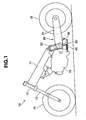
- a motor cycle 10 is structured, as shown in FIG. 1 , such that a front fork 13 and a front wheel 14 are mounted to a head pipe 12 provided in a front end portion of a frame 11 corresponding to a vehicle body side so as to be freely steered.
- a power unit 15 comprising an engine and a transmission and corresponding to the vehicle body side is mounted to a lower portion of the frame 11.
- a rear wheel 16 is mounted to a rear portion of the power unit 15 via a swing arm type suspension apparatus 20 in accordance with the present invention.
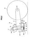
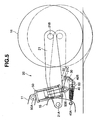
- the suspension apparatus 20 comprises, as shown in FIG. 2 , a base end portion of a swing arm 21 pivotally attached to the rear portion of the power unit 15 via a pivot shaft 21A so as to be freely oscillated.
- the rear wheel 16 is supported to a leading end portion of the swing arm 21 via an axle 21B so as to be freely rotated.
- the suspension apparatus 20 comprises a first link 30 pivotally attached to a lower bracket 22 provided in a lower portion of the swing arm 21 between the base end portion (the pivot shaft 21A) and the leading end portion (the axis 21B) of the swing arm 21, via a connection shaft 21C.
- the connection shaft 21C is arranged below a line obtained by connecting the pivot shaft 21A to the axle 21B.
- the suspension apparatus 20 comprises a second link 40 pivotally attached to a position below a pivot point (the pivot shaft 21A) to which the base end portion of the swing arm 21 in the power unit 15 is pivotally attached, via a connection shaft 40A.
- the first link 30 and the second link 40 are pivotally attached via a connection shaft 40B.
- the suspension apparatus 20 comprises an upper end of a cushion unit (a hydraulic shock absorber) 50 pivotally attached to the frame 11 via a connection shaft 50A, and a lower end of the cushion unit 50 pivotally attached to the first link 30 via a connection shaft 50B.
- the connection shaft 50A is arranged above the pivot shaft 21A of the power unit 15.
- the cushion unit 50 has a cylinder 51.
- a piston rod 52 is inserted into the cylinder 51, and is structured such that the cylinder 51 is mounted to the connection shaft 50A, and the piston rod 52 is mounted to the connection shaft 50B.
- the cushion unit 50 is provided with a suspension spring 53 comprising a compression coil spring between the cylinder 51 and the piston rod 52, and buffers an impact force which is applied to the vehicle from it's interaction with a road surface, on the basis of an expansion and contraction of the suspension spring 53.
- the cushion unit 50 comprises a working fluid sealed within the cylinder 51. Expansion side and compression side damping force generating apparatuses are provided in a piston 54 or the like arranged in an insertion end of the piston rod 52 to the cylinder 51, and damps an expanding and contracting vibration of the suspension spring 53.
- the second link 40 is structured as an expandable link 60.
- the expandable link 60 can be expanded and contracted, and is energized in a contracting direction.
- the expandable link 60 has a cylinder 61 and a piston rod 62 which is inserted into the cylinder 61 in a telescopic manner, as shown in FIG. 6 , and comprises a hydraulic damper in which a working fluid is sealed within the cylinder 61.
- the expandable link 60 comprises a compression coil spring 65 energizing in a direction that the cylinder 61 and the piston rod 62 are contracted with each other and being internally provided between a rod guide 63 sealed in an opening end of the cylinder 61 and being provided for the piston rod 62.
- a piston 64 is provided in an insertion end of the piston rod 62 to the cylinder 61.
- the expandable link 60 is provided with an expansion side damping force generating means 66 provided in an oil passage communicating two oil chambers 61A and 61B sectioned in an inner portion of the cylinder 61 by the piston 64 and comprises an orifice in the piston 64, and a check valve 67 provided in an oil passage communicating two oil chambers 61A and 61B bypassing the expansion side damping force generating means 66 during compression.
- the expansible link 60 comprises a stopper rubber 68A regulating an expanded end position of the piston 64 arranged in the oil chamber 61A to which the piston rod 62 is inserted in the inner portion of the cylinder 61, in a state of being backed up by a collar 68B.
- a stopper rubber 69A regulating a compressed end position of the piston 64 is arranged in the opposite side oil chamber 61B.
- the expandable link 60 is energized by a spring force of the spring 65 in the contracting direction, and has a damping force or a rebound force in the expanding direction.
- the expandable link 60 has a minimum length in a free state on the basis of the spring force of the spring 65.
- the suspension apparatus 20 comprises the piston rod 62 of the expansible link 60 (the second link 40) is connected to the power unit 15 via the connection shaft 40A.
- the cylinder 61 is connected to the first link 30 via the connection shaft 40B, and the expandable link 60 is set to a maximum expanded state ( FIG. 6 ) in a state of being assembled in the vehicle, a state in which a load of a rider or the like is not applied.
- a suspension apparatus 20 in accordance with an embodiment 2 shown in FIGS. 7A and 7B is different from the suspension apparatus 20 in accordance with the embodiment 1 in that the upper end of the cushion unit 50 is pivotally attached to an upper bracket 23 provided in an upper portion of the swing arm 21 in place of the frame 1, via the connection shaft 50A.
- the connection shaft 50A is arranged above a line connecting the pivot shaft 21A to the axle 21B.
- the expandable link 60 which is already completely expanded is regulated in the expansion of the axial direction so as to be a rigid body in the axial direction, and carries out a compression motion of the cushion unit 50.
- the expansion of the cushion unit 50 delays due to the existence of the expansion side damping force generating means when the swing arm 21 is going to move downward, whereby the swing arm 21 is not moved downward.
- the expandable link 60 is contracted on the basis of the energizing force in the contracting direction so as to pull the swing arm 21 to a lower side, at this time, the pivot point in the lower end portion of the cushion unit 50 (the connection shaft 50B) does not move.
- the swing arm 21 moves downward to the downward position in FIG. 7B from the assembled state in FIG. 7A . Accordingly, the rear wheel 16 is in contact with the road surface. It is possible to avoid a reduction of the driving force. It is also possible to maintain stability of the vehicle.
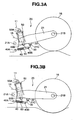
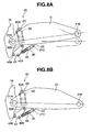
- a suspension apparatus 20 in accordance with an embodiment 3 shown in FIGS. 8A and 8B is different from the suspension apparatus 20 in accordance with the embodiment 2 in that the lower end of the cushion unit 50 is pivotally attached to the second link 40 in place of the first link 30, via the connection shaft 50B, and that the first link 30 comprises an expandable link 60.
- the expandable link 60 which is already in the maximum expansion position is regulated in it's expansion in the axial direction so as to be a rigid body in the axial direction, and thereby carries out a compression motion of the cushion unit 50.
- the expansion of the cushion unit 50 delays due to the existence of the expansion side damping force generating means when the swing arm 21 is going to move downward, whereby the swing arm 21 is not moved downward.
- the expandable link 60 is contracted on the basis of the energizing force in the contracting direction so as to pull the swing arm 21 to a lower side, at this time, the pivot point in the lower end portion of the cushion unit 50 (the connection shaft 50B) does not move, and the swing arm 21 moves downward to the downward position in FIG. 8B from the assembled state in FIG. 8A . Accordingly, the rear wheel 16 is in contact with the road surface. It is thereby possible to avoid reduction of the driving force, and it is possible to maintain stability of the vehicle.
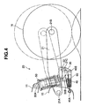
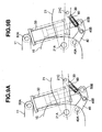
- a suspension apparatus 20 in accordance with an embodiment 4 shown in FIGS. 9A and 9B is different from the suspension apparatus 20 in accordance with the embodiment 1 in that the lower end of the cushion unit 50 is pivotally attached to the second link 40 in place of the first link 30, via the connection shaft 50B, and that the first link 30 comprises an expandable link 60.
- the second link 40 comprises a bell crank.
- the connection shaft 40B between the first link 30 (the expansible link 60) and the second link 40 is arranged at the midpoint of the connection shaft 40A between the second link 40 and the power unit 15, and the connection shaft 50B between the second link 40 and the cushion unit 50.
- the expandable link 60 which is already completely expanded is regulated in its expansion in the axial direction so as to be a rigid body in the axial direction, and carries out a compression motion of the cushion unit 50.
- the expansion of the cushion unit 50 delays due to the existence of the expansion side damping force generating means when the swing arm 21 is going to move downward. Whereby the swing arm 21 is not moved downward.
- the expandable link 60 is contracted at a moment on the basis of the energizing force in the contracting direction so as to pull the swing arm 21 to a lower side.
- the pivot point in the lower end portion of the cushion unit 50 (the connection shaft 50B) does not move, and the swing arm 21 moves downward to the downward position in FIG. 9B from the assembled state in FIG. 9A . Accordingly, the rear wheel 16 is in contact with the road surface. It is possible to avoid a reduction of the driving force, and it is possible to maintain stability of the vehicle.
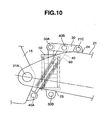
- a suspension apparatus 20 in accordance with an embodiment 5 shown in FIG. 10 is different from the suspension apparatus 20 in accordance with the embodiment 1 in that the first link 30 is pivotally attached to the upper bracket 24 of the swing arm 21 between the base end portion (the pivot shaft 21A) and the leading end portion (the axle 21B) of the swing arm 21, via the connection shaft 21C.
- the connection shaft 21C is arranged above the line connecting the pivot shaft 21A to the axle 21B.
- the upper end of the cushion unit 50 is pivotally attached to the first link 30 via the connection shaft 50A where the connection shaft 50A is arranged above the line connecting the pivot shaft 21A to the axle 21B.
- the lower end of the cushion unit 50 is pivotally attached to the lower bracket 25 of the swing arm 21 between the base end portion (the pivot shaft 21A) and the leading end portion (the axle 21B) of the swing arm 21, via the connection shaft 50B.
- the connection shaft 50B is arranged below the line connecting the pivot shaft 21A to the axle 21B.
- the second link 40 is connected to a portion between the connection shaft 21C to the swing arm 21 in the first link 30 via the connection shaft 40B, and the connection shaft 50A to the cushion unit 50.
- the expandable link 60 which is already completely expanded is regulated in the expansion in the axial direction so as to be a rigid body in the axial direction, and carries out a compression motion of the cushion unit 50.
- the expansion of the cushion unit 50 delays due to the existence of the expansion side damping force generating means when the swing arm 21 is going to move downward, whereby the swing arm 21 is not moved downward.
- the expandable link 60 is contracted at a moment on the basis of the energizing force in the contracting direction so as to pull the swing arm 21 to a lower side.
- the pivot point in the lower end portion of the cushion unit 50 (the connection shaft 50B) does not move, and the swing arm 21 moves downward from the assembled state. Accordingly, the rear wheel 16 is in contact with the road surface. It is possible to avoid a reduction of the driving force, and it is possible to maintain stability of the vehicle.
- the expandable link 60 may be provided between the connection shaft 21C to the swing arm 21 in the first link 30 to which the cushion unit 50 is pivotally attached, and the connection shaft 40 to the second link 40, or between the connection shaft 40A to the vehicle body side in the second link 40 to which the cushion unit 50 is pivotally attached, and the connection shaft 40B to the first link 30.
- the first link 30 or the second link 40 to which the cushion unit 50 is not pivotally attached is comprises the expansible link 60.
Landscapes
- Engineering & Computer Science (AREA)
- Mechanical Engineering (AREA)
- Vehicle Body Suspensions (AREA)
- Axle Suspensions And Sidecars For Cycles (AREA)
Claims (9)
- Aufhängungsvorrichtung eines Fahrzeugs, umfassend:einen Basisendabschnitt eines Schwingarms (21), welcher schwenkbar an einem Fahrzeug-Hauptrahmen angebracht ist, um frei zu schwingen, wobei ein Rad (16) drehbar an einem vorderen Endabschnitt des Schwingarms gelagert ist;ein erstes Verbindungsglied (30), welches schwenkbar an einem Abschnitt zwischen dem Basisabschnitt und dem vorderen Endabschnitt des Schwingarms angebracht ist, ein zweites Verbindungsglied (40), welches schwenkbar an dem Fahrzeug-Hauptrahmen in einer Position, welche sich unterhalb eines Drehpunkts, an welchem der Basisabschnitt des Schwingarms schwenkbar angebracht ist, an dem Fahrzeug-Hauptrahmen befindet, wobei das erste und das zweite Verbindungsglied schwenkbar angebracht sind;wobei ein Ende einer Dämpfungseinheit (50) schwenkbar an dem Fahrzeug-Hauptrahmen angebracht ist und ein anderes Ende der Dämpfungseinheit schwenkbar an einem Verbindungsglied aus der Gruppe des ersten und des zweiten Verbindungsglieds angebracht ist,dadurch gekennzeichnet, daß das erste Verbindungsglied oder das zweite Verbindungsglied ein ausziehbares Glied (60) umfaßt und das ausziehbare Glied in einer Auszugsposition positionierbar ist und in einer Kompressionsrichtung gespannt wird, unddadurch, daß das ausziehbare Glied eine Dämpfkraft-Erzeugungseinrichtung (66) der Auszugsseite und eine Einrichtung (67) zum Umgehen der Dämpfkraft-Erzeugungseinrichtung der Auszugsseite während einer Kompression umfaßt.
- Aufhängungsvorrichtung eines Fahrzeugs, umfassend:einen Basisendabschnitt eines Schwingarms (21), welcher schwenkbar an einem Fahrzeug-Hauptrahmen angebracht ist, um frei zu schwingen, wobei ein Rad (16) drehbar an einem vorderen Endabschnitt des Schwingarms gelagert ist;ein erstes Verbindungsglied (30), welches schwenkbar an einem Abschnitt zwischen dem Basisabschnitt und dem vorderen Endabschnitt des Schwingarms angebracht ist, ein zweites Verbindungsglied, welches schwenkbar an dem Fahrzeug-Hauptrahmen in einer Position, welche sich unterhalb eines Drehpunkts, an welchem der Basisabschnitt des Schwingarms schwenkbar angebracht ist, an dem Fahrzeug-Hauptrahmen befindet, wobei das erste und das zweite Verbindungsglied schwenkbar angebracht sind;wobei ein Ende einer Dämpfungseinheit (50) schwenkbar an dem Fahrzeug-Hauptrahmen angebracht ist und ein anderes Ende der Dämpfungseinheit schwenkbar an einem Verbindungsglied aus der Gruppe des ersten und des zweiten Verbindungsglieds angebracht ist,dadurch gekennzeichnet, daß das erste Verbindungsglied oder das zweite Verbindungsglied ein ausziehbares Glied (60) umfaßt und das ausziehbare Glied in einer Auszugsposition positionierbar ist und in einer Kompressionsrichtung gespannt wird, unddadurch, daß das ausziehbare Glied eine Dämpfkraft-Erzeugungseinrichtung (66) der Auszugsseite und eine Einrichtung (67) zum Umgehen der Dämpfkraft-Erzeugungseinrichtung der Auszugsseite während einer Kompression umfaßt.
- Aufhängungsvorrichtung eines Fahrzeugs nach Anspruch 1 oder 2, wobei das ausziehbare Verbindungsglied (60) eine maximale Ausdehnung erreicht, wenn dieses in dem Fahrzeug eingebaut ist.
- Aufhängungsvorrichtung eines Fahrzeugs nach einem der Ansprüche 1 bis 3, wobei das ausziehbare Verbindungsglied eine Kolbenstange (62), welche in einen Zylinder einführbar ist, und eine Feder, welche den Zylinder und die Kolbenstange in einer gegenseitigen Kontraktionsrichtung spannt, welche intern in dem Zylinder vorgesehen ist, umfaßt.
- Aufhängungsvorrichtung eines Fahrzeugs nach einem der Ansprüche 1 bis 4, wobei das ausziehbare Verbindungsglied einen hydraulischen Dämpfer umfaßt.
- Aufhängungsvorrichtung eines Fahrzeugs nach Anspruch 4, wobei die Feder eine Spiralfeder (65), welche zwischen einer Stangenführung für die Kolbenstange, welche dicht abschließend in einem Öffnungsende des Zylinders angebracht ist, und einem Kolben (64), welcher im Hinblick auf den Zylinder in einem Einführungsende der Kolbenstange (62) vorgesehen ist, umfaßt.
- Aufhängungsvorrichtung eines Fahrzeugs nach einem der Ansprüche 1 bis 6, wobei das ausziehbare Verbindungsglied die Kolbenstange (62), welche in den Zylinder einführbar ist, wobei der Kolben im Hinblick auf den Zylinder in dem Einführungsende der Kolbenstange vorgesehen ist, und
die Dämpfkraft-Erzeugungseinrichtung (66) der Auszugsseite, welche in dem Kolben vorgesehen ist und eine Öffnung umfaßt, welche in einem Ölkanal vorgesehen ist, welcher zwei Ölkammern (61A, 61B) verbindet, welche in einem inneren Abschnitt des Zylinders durch den Kolben getrennt sind, umfaßt. - Aufhängungsvorrichtung eines Fahrzeugs nach einem der Ansprüche 1 bis 7, wobei das ausziehbare Verbindungsglied die Kolbenstange (62), welche in den Zylinder einführbar ist, wobei der Kolben im Hinblick auf den Zylinder in dem Einführungsende der Kolbenstange vorgesehen ist, und
die Einrichtung zum Umgehen der Dämpfkraft-Erzeugungseinrichtung der Auszugsseite während einer Kompression, welche in dem Kolben vorgesehen ist, welche ein Rückschlagventil (67) umfaßt, welches in einem Ölkanal vorgesehen ist, welcher zwei Ölkammern (61A, 61B) verbindet, welche in einem inneren Abschnitt des Zylinders durch den Kolben getrennt sind, umfaßt. - Aufhängungsvorrichtung eines Fahrzeugs nach einem der Ansprüche 7 oder 8, wobei das ausziehbare Verbindungsglied einen ersten Sperrgummi (68A), welcher eine Auszugs-Endposition des Kolbens, welcher in einer Ölkammer einer Seite, worin die Kolbenstange eingeführt ist, in dem inneren Abschnitt des Zylinders angeordnet ist, reguliert, und einen zweiten Sperrgummi (69A), welcher eine Kompressionsendposition des Kolbens, welcher in einer Ölkammer der anderen Seite angeordnet ist, reguliert, umfaßt.
Applications Claiming Priority (2)
| Application Number | Priority Date | Filing Date | Title |
|---|---|---|---|
| JP2003398067 | 2003-11-27 | ||
| JP2003398067A JP2005153807A (ja) | 2003-11-27 | 2003-11-27 | 車両の懸架装置 |
Publications (4)
| Publication Number | Publication Date |
|---|---|
| EP1535828A2 EP1535828A2 (de) | 2005-06-01 |
| EP1535828A3 EP1535828A3 (de) | 2006-03-08 |
| EP1535828B1 EP1535828B1 (de) | 2008-05-14 |
| EP1535828B9 true EP1535828B9 (de) | 2008-10-15 |
Family
ID=34463855
Family Applications (1)
| Application Number | Title | Priority Date | Filing Date |
|---|---|---|---|
| EP04013386A Expired - Lifetime EP1535828B9 (de) | 2003-11-27 | 2004-06-07 | Aufhängungseinrichtung eines Fahrzeuges |
Country Status (4)
| Country | Link |
|---|---|
| US (1) | US7364000B2 (de) |
| EP (1) | EP1535828B9 (de) |
| JP (1) | JP2005153807A (de) |
| DE (1) | DE602004013705D1 (de) |
Cited By (1)
| Publication number | Priority date | Publication date | Assignee | Title |
|---|---|---|---|---|
| US9656529B2 (en) | 2013-02-12 | 2017-05-23 | Piaggio & C. S.P.A. | Suspension group in particular for motorized vehicles |
Families Citing this family (19)
| Publication number | Priority date | Publication date | Assignee | Title |
|---|---|---|---|---|
| JP5303292B2 (ja) * | 2009-01-30 | 2013-10-02 | 本田技研工業株式会社 | ユニットスイング式自動二輪車の防振構造 |
| ITBS20100060A1 (it) * | 2010-03-29 | 2011-09-30 | Beta Engineering Srl | Unita' di sospensione per motociclette e biciclette |
| US8262100B2 (en) | 2010-09-28 | 2012-09-11 | Georges Thomas | Vehicle height adjustment suspension device |
| ITBS20110074A1 (it) | 2011-05-23 | 2012-11-24 | Beta Engineering Srl | Dispositivo di sospensione/ammortizzatore ad azione progressiva per veicoli |
| CN102700671A (zh) * | 2012-06-03 | 2012-10-03 | 江苏金彭车业有限公司 | 电动三轮车后轮减震结构 |
| HUE026141T2 (en) * | 2012-11-30 | 2016-05-30 | Huebner Gmbh & Co Kg | Articulated vehicle with a wrist between vehicle parts |
| NL1039939C2 (en) * | 2012-12-10 | 2014-06-11 | Halbe Wietse Scheper | Motorcycle rear suspension hydraulic link system with controllable shock absorber displacement. |
| US9409459B2 (en) * | 2013-07-19 | 2016-08-09 | Papé Machinery, Inc. | 4-way leveling |
| US10875595B2 (en) | 2016-01-29 | 2020-12-29 | Bombardier Recreational Products Inc. | Three-wheeled straddle-seat vehicle |
| US9981711B2 (en) * | 2016-08-22 | 2018-05-29 | Big Cat Human Powered Vehicles, Llc | Suspended spindle assembly for recumbent tricyles |
| EP3661839A4 (de) | 2017-07-31 | 2020-08-19 | Bombardier Recreational Products Inc. | Fahrzeug mit einer aufhängungsanordnung mit einem schwenkarm |
| US11274940B2 (en) | 2018-06-08 | 2022-03-15 | Koepke InnoTek Ltd. T/A Motoklik | Suspension position monitoring system |
| JP7333137B2 (ja) * | 2021-03-31 | 2023-08-24 | 本田技研工業株式会社 | 車高調整機構 |
| IT202100008522A1 (it) * | 2021-04-06 | 2022-10-06 | Umbria Kinetics Srl | Sistema di oscillazione del forcellone di una ruota rispetto al telaio di un veicolo. |
| JP7815728B2 (ja) * | 2021-12-10 | 2026-02-18 | スズキ株式会社 | 後輪懸架装置 |
| JP7753851B2 (ja) * | 2021-12-10 | 2025-10-15 | スズキ株式会社 | 後輪懸架装置 |
| JP7457744B2 (ja) * | 2022-03-25 | 2024-03-28 | 本田技研工業株式会社 | 鞍乗り型車両の後輪懸架構造 |
| EP4414187A1 (de) * | 2023-02-10 | 2024-08-14 | Öhlins Racing AB | Aufhängungsanordnung zur einstellung einer fahrzeugaufhängung |
| IT202300023058A1 (it) * | 2023-11-02 | 2025-05-02 | Andrea Raffaelli | Sospensione a braccio oscillante con biellismo a cavaliere |
Family Cites Families (15)
| Publication number | Priority date | Publication date | Assignee | Title |
|---|---|---|---|---|
| US3158232A (en) * | 1962-12-06 | 1964-11-24 | Doetsch Hans Peter | Pneumatic vibration dampers |
| CA1137880A (en) * | 1979-10-04 | 1982-12-21 | Tokio Isono | Shock absorbing device for rear wheel of motorcycle |
| JPS5845388B2 (ja) * | 1979-10-16 | 1983-10-08 | スズキ株式会社 | 自動二輪車の後輪懸架装置 |
| JPS5929468A (ja) | 1982-08-11 | 1984-02-16 | Mitsubishi Electric Corp | 静電誘導トランジスタ |
| JPS5929468B2 (ja) | 1983-05-09 | 1984-07-20 | 本田技研工業株式会社 | 自動二輪車の後車輪緩衝装置 |
| US4712638A (en) * | 1985-06-25 | 1987-12-15 | Honda Giken Kogyo Kabushiki Kaisha | Suspension system for motorcycles |
| US5158161A (en) * | 1989-07-17 | 1992-10-27 | Atsugi Unisia Corporation | Reverse installation type variable damping force shock absorber variable of damping characteristics both for bounding and rebounding stroke motions |
| JP2981778B2 (ja) * | 1991-02-08 | 1999-11-22 | スズキ株式会社 | 自動二輪車の後輪懸架装置 |
| US5348112A (en) * | 1993-02-19 | 1994-09-20 | Works Performance Products, Inc. | Motorcycle height adjuster |
| JP3342254B2 (ja) * | 1995-09-07 | 2002-11-05 | ヤマハ発動機株式会社 | 自動二輪車のリヤサスペンション |
| US5810130A (en) * | 1997-03-14 | 1998-09-22 | General Motors Corporation | Suspension damper with rebound cut-off |
| US6071096A (en) * | 1997-04-25 | 2000-06-06 | Grasl; Andreas | Pneumatic cylinder, in particular for actuating fume extraction valves in fume and heat extraction plants |
| JP3768788B2 (ja) | 2000-09-05 | 2006-04-19 | 本田技研工業株式会社 | 車両のスイングアーム式懸架装置 |
| DE60200047T2 (de) * | 2002-05-24 | 2004-06-24 | Ducati Motor Holding S.P.A. | Hinterradfederung für ein Motorrad |
| US7328910B2 (en) * | 2004-12-01 | 2008-02-12 | Motoczysz Llc | Motorcycle rear suspension with linear spring rate and linkage controlled shock rate |
-
2003
- 2003-11-27 JP JP2003398067A patent/JP2005153807A/ja active Pending
-
2004
- 2004-06-04 US US10/860,915 patent/US7364000B2/en not_active Expired - Fee Related
- 2004-06-07 DE DE602004013705T patent/DE602004013705D1/de not_active Expired - Fee Related
- 2004-06-07 EP EP04013386A patent/EP1535828B9/de not_active Expired - Lifetime
Cited By (1)
| Publication number | Priority date | Publication date | Assignee | Title |
|---|---|---|---|---|
| US9656529B2 (en) | 2013-02-12 | 2017-05-23 | Piaggio & C. S.P.A. | Suspension group in particular for motorized vehicles |
Also Published As
| Publication number | Publication date |
|---|---|
| DE602004013705D1 (de) | 2008-06-26 |
| EP1535828A3 (de) | 2006-03-08 |
| EP1535828A2 (de) | 2005-06-01 |
| US7364000B2 (en) | 2008-04-29 |
| JP2005153807A (ja) | 2005-06-16 |
| US20050116437A1 (en) | 2005-06-02 |
| EP1535828B1 (de) | 2008-05-14 |
Similar Documents
| Publication | Publication Date | Title |
|---|---|---|
| EP1535828B1 (de) | Aufhängungseinrichtung eines Fahrzeuges | |
| JP3479647B2 (ja) | 振動ダンパー | |
| JP4890257B2 (ja) | モーションダンパ | |
| JP2002211437A (ja) | 車両用補強部材及び車体構造 | |
| JPS6264603A (ja) | 車輪懸架装置用油圧緩衝器における底突き防止装置 | |
| EP1944523B1 (de) | Dämpfer | |
| JP2013242016A (ja) | 懸架装置 | |
| KR950031566A (ko) | 상용 자동차의 현가장치 | |
| JP2003172395A (ja) | 自動二輪車のフロントフォーク | |
| KR20080055222A (ko) | 험지주행용 차량의 암형 능동 현가장치 | |
| JPH03200417A (ja) | ロールダンパ装置 | |
| JP3727089B2 (ja) | 倒立型フロントフォーク | |
| KR200318647Y1 (ko) | 자전거용 프레임의 충격흡수기구 | |
| KR100507122B1 (ko) | 맥퍼슨 스트럿형 현가장치의 스트럿 마찰 저감장치 | |
| JPH10220513A (ja) | サスペンション装置 | |
| JP2000205325A (ja) | 油圧緩衝器の減衰力調整装置 | |
| JP3840550B2 (ja) | 車両懸架装置 | |
| KR100482128B1 (ko) | 자동차의 쇽업소버 | |
| KR20030003533A (ko) | 자동차의 로워암 구조 | |
| JPH09123975A (ja) | 車両の車高調整装置 | |
| JP6577896B2 (ja) | 緩衝器 | |
| JP2006335160A (ja) | 車体の振動制御システムおよび振動制御方法 | |
| JP2001059536A (ja) | 油圧緩衝器の分解構造 | |
| JP4592943B2 (ja) | フロントフォーク | |
| JPH11117979A (ja) | 二輪車等のフロントフォーク |
Legal Events
| Date | Code | Title | Description |
|---|---|---|---|
| PUAI | Public reference made under article 153(3) epc to a published international application that has entered the european phase |
Free format text: ORIGINAL CODE: 0009012 |
|
| AK | Designated contracting states |
Kind code of ref document: A2 Designated state(s): AT BE BG CH CY CZ DE DK EE ES FI FR GB GR HU IE IT LI LU MC NL PL PT RO SE SI SK TR |
|
| AX | Request for extension of the european patent |
Extension state: AL HR LT LV MK |
|
| PUAL | Search report despatched |
Free format text: ORIGINAL CODE: 0009013 |
|
| AK | Designated contracting states |
Kind code of ref document: A3 Designated state(s): AT BE BG CH CY CZ DE DK EE ES FI FR GB GR HU IE IT LI LU MC NL PL PT RO SE SI SK TR |
|
| AX | Request for extension of the european patent |
Extension state: AL HR LT LV MK |
|
| 17P | Request for examination filed |
Effective date: 20060608 |
|
| 17Q | First examination report despatched |
Effective date: 20060829 |
|
| AKX | Designation fees paid |
Designated state(s): DE GB IT |
|
| 17Q | First examination report despatched |
Effective date: 20060829 |
|
| GRAP | Despatch of communication of intention to grant a patent |
Free format text: ORIGINAL CODE: EPIDOSNIGR1 |
|
| GRAS | Grant fee paid |
Free format text: ORIGINAL CODE: EPIDOSNIGR3 |
|
| GRAA | (expected) grant |
Free format text: ORIGINAL CODE: 0009210 |
|
| AK | Designated contracting states |
Kind code of ref document: B1 Designated state(s): DE GB IT |
|
| REG | Reference to a national code |
Ref country code: GB Ref legal event code: FG4D |
|
| REF | Corresponds to: |
Ref document number: 602004013705 Country of ref document: DE Date of ref document: 20080626 Kind code of ref document: P |
|
| PLBE | No opposition filed within time limit |
Free format text: ORIGINAL CODE: 0009261 |
|
| STAA | Information on the status of an ep patent application or granted ep patent |
Free format text: STATUS: NO OPPOSITION FILED WITHIN TIME LIMIT |
|
| 26N | No opposition filed |
Effective date: 20090217 |
|
| PGFP | Annual fee paid to national office [announced via postgrant information from national office to epo] |
Ref country code: IT Payment date: 20090617 Year of fee payment: 6 |
|
| PGFP | Annual fee paid to national office [announced via postgrant information from national office to epo] |
Ref country code: DE Payment date: 20090604 Year of fee payment: 6 Ref country code: GB Payment date: 20090603 Year of fee payment: 6 |
|
| GBPC | Gb: european patent ceased through non-payment of renewal fee |
Effective date: 20100607 |
|
| PG25 | Lapsed in a contracting state [announced via postgrant information from national office to epo] |
Ref country code: IT Free format text: LAPSE BECAUSE OF NON-PAYMENT OF DUE FEES Effective date: 20100607 |
|
| PG25 | Lapsed in a contracting state [announced via postgrant information from national office to epo] |
Ref country code: DE Free format text: LAPSE BECAUSE OF NON-PAYMENT OF DUE FEES Effective date: 20110101 |
|
| PG25 | Lapsed in a contracting state [announced via postgrant information from national office to epo] |
Ref country code: GB Free format text: LAPSE BECAUSE OF NON-PAYMENT OF DUE FEES Effective date: 20100607 |