EP1535828B9 - Suspension apparatus of vehicle - Google Patents
Suspension apparatus of vehicle Download PDFInfo
- Publication number
- EP1535828B9 EP1535828B9 EP04013386A EP04013386A EP1535828B9 EP 1535828 B9 EP1535828 B9 EP 1535828B9 EP 04013386 A EP04013386 A EP 04013386A EP 04013386 A EP04013386 A EP 04013386A EP 1535828 B9 EP1535828 B9 EP 1535828B9
- Authority
- EP
- European Patent Office
- Prior art keywords
- link
- pivotally attached
- swing arm
- vehicle
- expandable
- Prior art date
- Legal status (The legal status is an assumption and is not a legal conclusion. Google has not performed a legal analysis and makes no representation as to the accuracy of the status listed.)
- Expired - Lifetime
Links
- 239000000725 suspension Substances 0.000 title claims description 51
- 238000013016 damping Methods 0.000 claims description 20
- 230000006835 compression Effects 0.000 claims description 13
- 238000007906 compression Methods 0.000 claims description 13
- 230000001105 regulatory effect Effects 0.000 claims description 10
- 230000037431 insertion Effects 0.000 claims description 5
- 238000003780 insertion Methods 0.000 claims description 5
- 230000000694 effects Effects 0.000 description 13
- 230000001934 delay Effects 0.000 description 5
- 239000006096 absorbing agent Substances 0.000 description 2
- 239000012530 fluid Substances 0.000 description 2
- 230000035939 shock Effects 0.000 description 2
- 230000005540 biological transmission Effects 0.000 description 1
- 239000000872 buffer Substances 0.000 description 1
- 230000008602 contraction Effects 0.000 description 1
- 230000003993 interaction Effects 0.000 description 1
Images


Classifications
-
- B—PERFORMING OPERATIONS; TRANSPORTING
- B62—LAND VEHICLES FOR TRAVELLING OTHERWISE THAN ON RAILS
- B62K—CYCLES; CYCLE FRAMES; CYCLE STEERING DEVICES; RIDER-OPERATED TERMINAL CONTROLS SPECIALLY ADAPTED FOR CYCLES; CYCLE AXLE SUSPENSIONS; CYCLE SIDE-CARS, FORECARS, OR THE LIKE
- B62K25/00—Axle suspensions
- B62K25/04—Axle suspensions for mounting axles resiliently on cycle frame or fork
- B62K25/28—Axle suspensions for mounting axles resiliently on cycle frame or fork with pivoted chain-stay
- B62K25/283—Axle suspensions for mounting axles resiliently on cycle frame or fork with pivoted chain-stay for cycles without a pedal crank, e.g. motorcycles
-
- B—PERFORMING OPERATIONS; TRANSPORTING
- B62—LAND VEHICLES FOR TRAVELLING OTHERWISE THAN ON RAILS
- B62K—CYCLES; CYCLE FRAMES; CYCLE STEERING DEVICES; RIDER-OPERATED TERMINAL CONTROLS SPECIALLY ADAPTED FOR CYCLES; CYCLE AXLE SUSPENSIONS; CYCLE SIDE-CARS, FORECARS, OR THE LIKE
- B62K25/00—Axle suspensions
- B62K25/04—Axle suspensions for mounting axles resiliently on cycle frame or fork
- B62K25/28—Axle suspensions for mounting axles resiliently on cycle frame or fork with pivoted chain-stay
- B62K25/286—Axle suspensions for mounting axles resiliently on cycle frame or fork with pivoted chain-stay the shock absorber being connected to the chain-stay via a linkage mechanism
-
- B—PERFORMING OPERATIONS; TRANSPORTING
- B60—VEHICLES IN GENERAL
- B60G—VEHICLE SUSPENSION ARRANGEMENTS
- B60G2200/00—Indexing codes relating to suspension types
- B60G2200/10—Independent suspensions
- B60G2200/13—Independent suspensions with longitudinal arms only
- B60G2200/132—Independent suspensions with longitudinal arms only with a single trailing arm
-
- B—PERFORMING OPERATIONS; TRANSPORTING
- B60—VEHICLES IN GENERAL
- B60G—VEHICLE SUSPENSION ARRANGEMENTS
- B60G2204/00—Indexing codes related to suspensions per se or to auxiliary parts
- B60G2204/10—Mounting of suspension elements
- B60G2204/12—Mounting of springs or dampers
- B60G2204/129—Damper mount on wheel suspension or knuckle
-
- B—PERFORMING OPERATIONS; TRANSPORTING
- B60—VEHICLES IN GENERAL
- B60G—VEHICLE SUSPENSION ARRANGEMENTS
- B60G2204/00—Indexing codes related to suspensions per se or to auxiliary parts
- B60G2204/40—Auxiliary suspension parts; Adjustment of suspensions
- B60G2204/421—Pivoted lever mechanisms for mounting suspension elements, e.g. Watt linkage
-
- B—PERFORMING OPERATIONS; TRANSPORTING
- B60—VEHICLES IN GENERAL
- B60G—VEHICLE SUSPENSION ARRANGEMENTS
- B60G2300/00—Indexing codes relating to the type of vehicle
- B60G2300/12—Cycles; Motorcycles
Definitions
- the present invention relates to a suspension apparatus of a vehicle in which a cushion unit (a hydraulic shock absorber) is provided between a vehicle body and a swing arm.
- a cushion unit a hydraulic shock absorber
- JP-B Japanese Patent Publication No. 59-29468
- a base end portion of a swing arm is pivotally attached to a vehicle body so as to freely oscillate.
- a wheel is rotatably supported to a leading end portion of the swing arm.
- a first link is pivotally attached to a portion between the base end portion and the leading end portion of the swing arm.
- a second link is pivotally attached to a position which is below a pivot point to which the base end portion of the swing arm is pivotally attached in the vehicle body.
- the first link and the second link are pivotally attached.
- One end of a cushion unit is pivotally attached to the vehicle body, and another end of the cushion unit is pivotally attached to one of the first link and the second link.
- JP-A Japanese Patent publication No. 2002-68066
- a base end portion of a swing arm is pivotally attached to a vehicle body so as to freely oscillate.
- a wheel is rotatably supported to a leading end portion of the swing arm.
- a first link is pivotally attached to a portion between the base end portion and the leading end portion of the swing arm.
- a second link is pivotally attached to a position which is below a pivot point to which the base end portion of the swing arm is pivotally attached in the vehicle body.
- the first link and the second link are pivotally attached.
- One end of a cushion unit is pivotally attached to the swing arm, and another end of the cushion unit is pivotally attached to one of the first link and the second link.
- An object of the present invention is to improve a road surface following property or road holding of a wheel in a suspension apparatus of a vehicle in which a cushion unit is provided between a vehicle body and a swing arm.
- the present invention relates to a suspension apparatus of a vehicle structured such that a base end portion of a swing arm is pivotally attached to a vehicle body so as to freely oscillate, and a wheel is rotatably supported to a leading end portion of the swing arm.
- a first link is pivotally attached to a portion between the base end portion and the leading end portion of the swing arm.
- a second link is pivotally attached to a position which is below a pivot point to which the base end portion of the swing arm is pivotally attached in the vehicle body.
- the first link and the second link are pivotally attached.
- One end of a cushion unit is pivotally attached to the vehicle body, and another end of the cushion unit is pivotally attached to one of the first link and the second link.
- the first link or the second link is an expandable link, and the expandable link is in an expandable manner and is energized in a contracting direction.
- the present invention relates to a suspension apparatus of a vehicle comprising a base end portion of a swing arm pivotally attached to a vehicle body so as to freely oscillate, and a wheel rotatably supported to a leading end portion of the swing arm.
- a first link is pivotally attached to a portion between the base end portion and the leading end portion of the swing arm.
- a second link is pivotally attached to a position which is below a pivot point to which the base end portion of the swing arm is pivotally attached in the vehicle body.
- the first link and the second link are pivotally attached.
- One end of a cushion unit is pivotally attached to the swing arm, and another end of the cushion unit is pivotally attached to one of the first link and the second link.
- the first link or the second link comprises an expandable link, and the expandable link is in an expandable manner and is energized in a contracting direction.
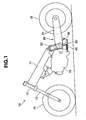
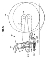
- a motor cycle 10 is structured, as shown in FIG. 1 , such that a front fork 13 and a front wheel 14 are mounted to a head pipe 12 provided in a front end portion of a frame 11 corresponding to a vehicle body side so as to be freely steered.
- a power unit 15 comprising an engine and a transmission and corresponding to the vehicle body side is mounted to a lower portion of the frame 11.
- a rear wheel 16 is mounted to a rear portion of the power unit 15 via a swing arm type suspension apparatus 20 in accordance with the present invention.
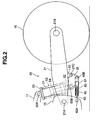
- the suspension apparatus 20 comprises, as shown in FIG. 2 , a base end portion of a swing arm 21 pivotally attached to the rear portion of the power unit 15 via a pivot shaft 21A so as to be freely oscillated.
- the rear wheel 16 is supported to a leading end portion of the swing arm 21 via an axle 21B so as to be freely rotated.
- the suspension apparatus 20 comprises a first link 30 pivotally attached to a lower bracket 22 provided in a lower portion of the swing arm 21 between the base end portion (the pivot shaft 21A) and the leading end portion (the axis 21B) of the swing arm 21, via a connection shaft 21C.
- the connection shaft 21C is arranged below a line obtained by connecting the pivot shaft 21A to the axle 21B.
- the suspension apparatus 20 comprises a second link 40 pivotally attached to a position below a pivot point (the pivot shaft 21A) to which the base end portion of the swing arm 21 in the power unit 15 is pivotally attached, via a connection shaft 40A.
- the first link 30 and the second link 40 are pivotally attached via a connection shaft 40B.
- the suspension apparatus 20 comprises an upper end of a cushion unit (a hydraulic shock absorber) 50 pivotally attached to the frame 11 via a connection shaft 50A, and a lower end of the cushion unit 50 pivotally attached to the first link 30 via a connection shaft 50B.
- the connection shaft 50A is arranged above the pivot shaft 21A of the power unit 15.
- the cushion unit 50 has a cylinder 51.
- a piston rod 52 is inserted into the cylinder 51, and is structured such that the cylinder 51 is mounted to the connection shaft 50A, and the piston rod 52 is mounted to the connection shaft 50B.
- the cushion unit 50 is provided with a suspension spring 53 comprising a compression coil spring between the cylinder 51 and the piston rod 52, and buffers an impact force which is applied to the vehicle from it's interaction with a road surface, on the basis of an expansion and contraction of the suspension spring 53.
- the cushion unit 50 comprises a working fluid sealed within the cylinder 51. Expansion side and compression side damping force generating apparatuses are provided in a piston 54 or the like arranged in an insertion end of the piston rod 52 to the cylinder 51, and damps an expanding and contracting vibration of the suspension spring 53.
- the second link 40 is structured as an expandable link 60.
- the expandable link 60 can be expanded and contracted, and is energized in a contracting direction.
- the expandable link 60 has a cylinder 61 and a piston rod 62 which is inserted into the cylinder 61 in a telescopic manner, as shown in FIG. 6 , and comprises a hydraulic damper in which a working fluid is sealed within the cylinder 61.
- the expandable link 60 comprises a compression coil spring 65 energizing in a direction that the cylinder 61 and the piston rod 62 are contracted with each other and being internally provided between a rod guide 63 sealed in an opening end of the cylinder 61 and being provided for the piston rod 62.
- a piston 64 is provided in an insertion end of the piston rod 62 to the cylinder 61.
- the expandable link 60 is provided with an expansion side damping force generating means 66 provided in an oil passage communicating two oil chambers 61A and 61B sectioned in an inner portion of the cylinder 61 by the piston 64 and comprises an orifice in the piston 64, and a check valve 67 provided in an oil passage communicating two oil chambers 61A and 61B bypassing the expansion side damping force generating means 66 during compression.
- the expansible link 60 comprises a stopper rubber 68A regulating an expanded end position of the piston 64 arranged in the oil chamber 61A to which the piston rod 62 is inserted in the inner portion of the cylinder 61, in a state of being backed up by a collar 68B.
- a stopper rubber 69A regulating a compressed end position of the piston 64 is arranged in the opposite side oil chamber 61B.
- the expandable link 60 is energized by a spring force of the spring 65 in the contracting direction, and has a damping force or a rebound force in the expanding direction.
- the expandable link 60 has a minimum length in a free state on the basis of the spring force of the spring 65.
- the suspension apparatus 20 comprises the piston rod 62 of the expansible link 60 (the second link 40) is connected to the power unit 15 via the connection shaft 40A.
- the cylinder 61 is connected to the first link 30 via the connection shaft 40B, and the expandable link 60 is set to a maximum expanded state ( FIG. 6 ) in a state of being assembled in the vehicle, a state in which a load of a rider or the like is not applied.
- a suspension apparatus 20 in accordance with an embodiment 2 shown in FIGS. 7A and 7B is different from the suspension apparatus 20 in accordance with the embodiment 1 in that the upper end of the cushion unit 50 is pivotally attached to an upper bracket 23 provided in an upper portion of the swing arm 21 in place of the frame 1, via the connection shaft 50A.
- the connection shaft 50A is arranged above a line connecting the pivot shaft 21A to the axle 21B.
- the expandable link 60 which is already completely expanded is regulated in the expansion of the axial direction so as to be a rigid body in the axial direction, and carries out a compression motion of the cushion unit 50.
- the expansion of the cushion unit 50 delays due to the existence of the expansion side damping force generating means when the swing arm 21 is going to move downward, whereby the swing arm 21 is not moved downward.
- the expandable link 60 is contracted on the basis of the energizing force in the contracting direction so as to pull the swing arm 21 to a lower side, at this time, the pivot point in the lower end portion of the cushion unit 50 (the connection shaft 50B) does not move.
- the swing arm 21 moves downward to the downward position in FIG. 7B from the assembled state in FIG. 7A . Accordingly, the rear wheel 16 is in contact with the road surface. It is possible to avoid a reduction of the driving force. It is also possible to maintain stability of the vehicle.
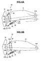
- a suspension apparatus 20 in accordance with an embodiment 3 shown in FIGS. 8A and 8B is different from the suspension apparatus 20 in accordance with the embodiment 2 in that the lower end of the cushion unit 50 is pivotally attached to the second link 40 in place of the first link 30, via the connection shaft 50B, and that the first link 30 comprises an expandable link 60.
- the expandable link 60 which is already in the maximum expansion position is regulated in it's expansion in the axial direction so as to be a rigid body in the axial direction, and thereby carries out a compression motion of the cushion unit 50.
- the expansion of the cushion unit 50 delays due to the existence of the expansion side damping force generating means when the swing arm 21 is going to move downward, whereby the swing arm 21 is not moved downward.
- the expandable link 60 is contracted on the basis of the energizing force in the contracting direction so as to pull the swing arm 21 to a lower side, at this time, the pivot point in the lower end portion of the cushion unit 50 (the connection shaft 50B) does not move, and the swing arm 21 moves downward to the downward position in FIG. 8B from the assembled state in FIG. 8A . Accordingly, the rear wheel 16 is in contact with the road surface. It is thereby possible to avoid reduction of the driving force, and it is possible to maintain stability of the vehicle.
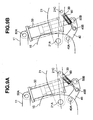
- a suspension apparatus 20 in accordance with an embodiment 4 shown in FIGS. 9A and 9B is different from the suspension apparatus 20 in accordance with the embodiment 1 in that the lower end of the cushion unit 50 is pivotally attached to the second link 40 in place of the first link 30, via the connection shaft 50B, and that the first link 30 comprises an expandable link 60.
- the second link 40 comprises a bell crank.
- the connection shaft 40B between the first link 30 (the expansible link 60) and the second link 40 is arranged at the midpoint of the connection shaft 40A between the second link 40 and the power unit 15, and the connection shaft 50B between the second link 40 and the cushion unit 50.
- the expandable link 60 which is already completely expanded is regulated in its expansion in the axial direction so as to be a rigid body in the axial direction, and carries out a compression motion of the cushion unit 50.
- the expansion of the cushion unit 50 delays due to the existence of the expansion side damping force generating means when the swing arm 21 is going to move downward. Whereby the swing arm 21 is not moved downward.
- the expandable link 60 is contracted at a moment on the basis of the energizing force in the contracting direction so as to pull the swing arm 21 to a lower side.
- the pivot point in the lower end portion of the cushion unit 50 (the connection shaft 50B) does not move, and the swing arm 21 moves downward to the downward position in FIG. 9B from the assembled state in FIG. 9A . Accordingly, the rear wheel 16 is in contact with the road surface. It is possible to avoid a reduction of the driving force, and it is possible to maintain stability of the vehicle.
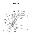
- a suspension apparatus 20 in accordance with an embodiment 5 shown in FIG. 10 is different from the suspension apparatus 20 in accordance with the embodiment 1 in that the first link 30 is pivotally attached to the upper bracket 24 of the swing arm 21 between the base end portion (the pivot shaft 21A) and the leading end portion (the axle 21B) of the swing arm 21, via the connection shaft 21C.
- the connection shaft 21C is arranged above the line connecting the pivot shaft 21A to the axle 21B.
- the upper end of the cushion unit 50 is pivotally attached to the first link 30 via the connection shaft 50A where the connection shaft 50A is arranged above the line connecting the pivot shaft 21A to the axle 21B.
- the lower end of the cushion unit 50 is pivotally attached to the lower bracket 25 of the swing arm 21 between the base end portion (the pivot shaft 21A) and the leading end portion (the axle 21B) of the swing arm 21, via the connection shaft 50B.
- the connection shaft 50B is arranged below the line connecting the pivot shaft 21A to the axle 21B.
- the second link 40 is connected to a portion between the connection shaft 21C to the swing arm 21 in the first link 30 via the connection shaft 40B, and the connection shaft 50A to the cushion unit 50.
- the expandable link 60 which is already completely expanded is regulated in the expansion in the axial direction so as to be a rigid body in the axial direction, and carries out a compression motion of the cushion unit 50.
- the expansion of the cushion unit 50 delays due to the existence of the expansion side damping force generating means when the swing arm 21 is going to move downward, whereby the swing arm 21 is not moved downward.
- the expandable link 60 is contracted at a moment on the basis of the energizing force in the contracting direction so as to pull the swing arm 21 to a lower side.
- the pivot point in the lower end portion of the cushion unit 50 (the connection shaft 50B) does not move, and the swing arm 21 moves downward from the assembled state. Accordingly, the rear wheel 16 is in contact with the road surface. It is possible to avoid a reduction of the driving force, and it is possible to maintain stability of the vehicle.
- the expandable link 60 may be provided between the connection shaft 21C to the swing arm 21 in the first link 30 to which the cushion unit 50 is pivotally attached, and the connection shaft 40 to the second link 40, or between the connection shaft 40A to the vehicle body side in the second link 40 to which the cushion unit 50 is pivotally attached, and the connection shaft 40B to the first link 30.
- the first link 30 or the second link 40 to which the cushion unit 50 is not pivotally attached is comprises the expansible link 60.
Landscapes
- Engineering & Computer Science (AREA)
- Mechanical Engineering (AREA)
- Vehicle Body Suspensions (AREA)
- Axle Suspensions And Sidecars For Cycles (AREA)
Description
- The present invention relates to a suspension apparatus of a vehicle in which a cushion unit (a hydraulic shock absorber) is provided between a vehicle body and a swing arm.
- In a conventional suspension apparatus of a vehicle, as described in
Japanese Patent Publication No. 59-29468 - In another conventional suspension apparatus of a vehicle, as described in
Japanese Patent publication No. 2002-68066 - In the suspension apparatus of the vehicle in accordance with
JP-B 59-29468 JP-A 2002-68066 - An object of the present invention is to improve a road surface following property or road holding of a wheel in a suspension apparatus of a vehicle in which a cushion unit is provided between a vehicle body and a swing arm.
- The present invention relates to a suspension apparatus of a vehicle structured such that a base end portion of a swing arm is pivotally attached to a vehicle body so as to freely oscillate, and a wheel is rotatably supported to a leading end portion of the swing arm. A first link is pivotally attached to a portion between the base end portion and the leading end portion of the swing arm. A second link is pivotally attached to a position which is below a pivot point to which the base end portion of the swing arm is pivotally attached in the vehicle body. The first link and the second link are pivotally attached. One end of a cushion unit is pivotally attached to the vehicle body, and another end of the cushion unit is pivotally attached to one of the first link and the second link. The first link or the second link is an expandable link, and the expandable link is in an expandable manner and is energized in a contracting direction.
- The present invention relates to a suspension apparatus of a vehicle comprising a base end portion of a swing arm pivotally attached to a vehicle body so as to freely oscillate, and a wheel rotatably supported to a leading end portion of the swing arm. A first link is pivotally attached to a portion between the base end portion and the leading end portion of the swing arm. A second link is pivotally attached to a position which is below a pivot point to which the base end portion of the swing arm is pivotally attached in the vehicle body. The first link and the second link are pivotally attached. One end of a cushion unit is pivotally attached to the swing arm, and another end of the cushion unit is pivotally attached to one of the first link and the second link. The first link or the second link comprises an expandable link, and the expandable link is in an expandable manner and is energized in a contracting direction.
- The present invention will be more fully understood from the detailed description given below and from the accompanying drawings which should not be taken to be a limitation on the invention, but are for explanation and understanding only.
The drawings: -
FIG. 1 is a schematic view showing a motor cycle to which the present invention is applied; -
FIG. 2 is a schematic view showing an assembled state of a suspension apparatus in accordance with anembodiment 1; -
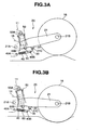
FIGS. 3A and 3B show an operating state of the suspension apparatus in accordance with theembodiment 1, in whichFIG. 3A is a schematic view showing an upward moving state of the swing arm, andFIG. 3B is a schematic view showing a downward moving state of the swing arm; -
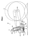
FIG. 4 is a schematic view showing the assembled state and the swing arm upward moving state of theembodiment 1 in an overlapping manner; -
FIG. 5 is a schematic view showing the assembled state and the swing arm downward moving state of theembodiment 1 in an overlapping manner; -
FIG. 6 is a schematic view showing an expandable link; -
FIGS. 7A and 7B show a suspension apparatus in accordance with anembodiment 2, in whichFIG. 7A is a schematic view showing an assembled state andFIG. 7B is a schematic view showing a downward moving state of a swing arm; -
FIGS. 8A and 8B show a suspension apparatus in accordance with an embodiment 3, in whichFIG. 8A is a schematic view showing an assembled state andFIG. 8B is a schematic view showing a downward moving state of a swing arm; -
FIGS. 9A and 9B show a suspension apparatus in accordance with an embodiment 4, in whichFIG. 9A is a schematic view showing an assembled state andFIG. 9B is a schematic view showing a downward moving state of a swing arm; and -
FIG. 10 is a schematic view showing a suspension apparatus in accordance with an embodiment 5. - A
motor cycle 10 is structured, as shown inFIG. 1 , such that afront fork 13 and afront wheel 14 are mounted to ahead pipe 12 provided in a front end portion of aframe 11 corresponding to a vehicle body side so as to be freely steered. Apower unit 15 comprising an engine and a transmission and corresponding to the vehicle body side is mounted to a lower portion of theframe 11. Arear wheel 16 is mounted to a rear portion of thepower unit 15 via a swing armtype suspension apparatus 20 in accordance with the present invention. - The
suspension apparatus 20 comprises, as shown inFIG. 2 , a base end portion of aswing arm 21 pivotally attached to the rear portion of thepower unit 15 via apivot shaft 21A so as to be freely oscillated. Therear wheel 16 is supported to a leading end portion of theswing arm 21 via anaxle 21B so as to be freely rotated. - The
suspension apparatus 20 comprises afirst link 30 pivotally attached to alower bracket 22 provided in a lower portion of theswing arm 21 between the base end portion (thepivot shaft 21A) and the leading end portion (theaxis 21B) of theswing arm 21, via aconnection shaft 21C. Theconnection shaft 21C is arranged below a line obtained by connecting thepivot shaft 21A to theaxle 21B. - The
suspension apparatus 20 comprises asecond link 40 pivotally attached to a position below a pivot point (thepivot shaft 21A) to which the base end portion of theswing arm 21 in thepower unit 15 is pivotally attached, via aconnection shaft 40A. Thefirst link 30 and thesecond link 40 are pivotally attached via aconnection shaft 40B. - The
suspension apparatus 20 comprises an upper end of a cushion unit (a hydraulic shock absorber) 50 pivotally attached to theframe 11 via aconnection shaft 50A, and a lower end of thecushion unit 50 pivotally attached to thefirst link 30 via aconnection shaft 50B. Theconnection shaft 50A is arranged above thepivot shaft 21A of thepower unit 15. - The
cushion unit 50 has acylinder 51. Apiston rod 52 is inserted into thecylinder 51, and is structured such that thecylinder 51 is mounted to theconnection shaft 50A, and thepiston rod 52 is mounted to theconnection shaft 50B. Thecushion unit 50 is provided with asuspension spring 53 comprising a compression coil spring between thecylinder 51 and thepiston rod 52, and buffers an impact force which is applied to the vehicle from it's interaction with a road surface, on the basis of an expansion and contraction of thesuspension spring 53. Thecushion unit 50 comprises a working fluid sealed within thecylinder 51. Expansion side and compression side damping force generating apparatuses are provided in apiston 54 or the like arranged in an insertion end of thepiston rod 52 to thecylinder 51, and damps an expanding and contracting vibration of thesuspension spring 53. - Accordingly, in the
suspension apparatus 20, thesecond link 40 is structured as anexpandable link 60. Theexpandable link 60 can be expanded and contracted, and is energized in a contracting direction. - The
expandable link 60 has acylinder 61 and apiston rod 62 which is inserted into thecylinder 61 in a telescopic manner, as shown inFIG. 6 , and comprises a hydraulic damper in which a working fluid is sealed within thecylinder 61. Theexpandable link 60 comprises acompression coil spring 65 energizing in a direction that thecylinder 61 and thepiston rod 62 are contracted with each other and being internally provided between arod guide 63 sealed in an opening end of thecylinder 61 and being provided for thepiston rod 62. Apiston 64 is provided in an insertion end of thepiston rod 62 to thecylinder 61. Theexpandable link 60 is provided with an expansion side damping force generating means 66 provided in an oil passage communicating twooil chambers cylinder 61 by thepiston 64 and comprises an orifice in thepiston 64, and acheck valve 67 provided in an oil passage communicating twooil chambers expansible link 60 comprises astopper rubber 68A regulating an expanded end position of thepiston 64 arranged in theoil chamber 61A to which thepiston rod 62 is inserted in the inner portion of thecylinder 61, in a state of being backed up by acollar 68B. Astopper rubber 69A regulating a compressed end position of thepiston 64 is arranged in the oppositeside oil chamber 61B. In other words, theexpandable link 60 is energized by a spring force of thespring 65 in the contracting direction, and has a damping force or a rebound force in the expanding direction. Theexpandable link 60 has a minimum length in a free state on the basis of the spring force of thespring 65. - The
suspension apparatus 20 comprises thepiston rod 62 of the expansible link 60 (the second link 40) is connected to thepower unit 15 via theconnection shaft 40A. Thecylinder 61 is connected to thefirst link 30 via theconnection shaft 40B, and theexpandable link 60 is set to a maximum expanded state (FIG. 6 ) in a state of being assembled in the vehicle, a state in which a load of a rider or the like is not applied. - A description will be given below of the operation and effect of the
suspension apparatus 20 in accordance with anembodiment 1. - (a) In the case that the rider rides on the vehicle or the vehicle runs against a projection on the road surface, whereby the
swing arm 21 is moved upward (FIG. 4 ) from an assembled state inFIG. 2 to an upward moved state inFIG. 3A , theexpandable link 60 which is already in it's most expanded position is regulated in the expansion in the axial direction so as to be a rigid body in the axial direction, and carries out a compression motion of thecushion unit 50.
In the case that the load applied to therear wheel 16 from the road surface is reduced while running along the road surface gap (the recess) or while braking the vehicle, the expansion of thecushion unit 50 delays due to the existence of the expansion side damping force generating means when theswing arm 21 is going to move downward. Theswing arm 21 is thereby not moved downward. Theexpandable link 60 is contracted at a moment on the basis of the energizing force in the contracting direction so as to pull theswing arm 21 to a lower side. At this time, the pivot point (theconnection shaft 50B) in the lower end portion of thecushion unit 50 does not move. Theswing arm 21 moves downward to the downward position inFIG. 3B from the assembled state inFIG. 2 (FIG. 5 ). Accordingly, therear wheel 16 is in contact with the road surface. It is possible to avoid a reduction of the driving force, and it is possible to maintain stability of the vehicle. - (b) The
expandable link 60 is energized in the contracting direction, and is kept at a minimum length in the free state. However, it is kept at a maximum length on the basis of the spring force of thesuspension spring 53 of thecushion unit 50 or the like in a state of being assembled in the vehicle. Accordingly, when the rider rides on the vehicle, the vehicle runs against the projection on the road surface and theswing arm 21 moves upward as described in the item (a) mentioned above. Theexpandable link 60 is securely regulated in expansion in the axial direction so as to be a rigid body in the axial direction. Thereby compressing thecushion unit 50. - (c) The
expandable link 60 generates the expansion side damping force during a period that theswing arm 21 moves downward in accordance with the item (a) mentioned above. Therear wheel 16 gets free of the recess on the road surface after being in contact with the recess on the road surface, and theswing arm 21 again moves upward. In other words, during a period that theexpansible link 60 is extended from the contracted state to the assembled state to the vehicle, the maximum length state. Accordingly, theexpandable link 60 absorbs an upthrow input from the road surface, and improves ride quality. Further, it is possible to prevent the impact generated when theexpandable link 60 is fully expanded, thepiston rod 62 being prevented from coming into collision with therod guide 63 of thecylinder 61. - (d) Since the
expansible link 60 is provided with the means (the check valve 67) for bypassing the extension side damping force generating means 66 during compression, theexpandable link 60 is rapidly set to the contracted state when theswing arm 21 moves downward in accordance with the item (a) mentioned above. It is thereby possible to secure the road holding or the road surface following property of therear wheel 16. - (e) Since the
expandable link 60 is internally provided with thespring 65 energizing in the contracting direction of thecylinder 61, it is possible to improve operability of theexpandable link 60. - (f) The
expandable link 60 can easily assemble the expansion side damping force generating means 66 and the bypassing means thereof, by structuring the hydraulic damper. - A
suspension apparatus 20 in accordance with anembodiment 2 shown inFIGS. 7A and 7B is different from thesuspension apparatus 20 in accordance with theembodiment 1 in that the upper end of thecushion unit 50 is pivotally attached to anupper bracket 23 provided in an upper portion of theswing arm 21 in place of theframe 1, via theconnection shaft 50A. Theconnection shaft 50A is arranged above a line connecting thepivot shaft 21A to theaxle 21B. - In accordance with the
suspension apparatus 20 of theembodiment 2, the following operations and effects are achieved. - In the case that the rider rides on the vehicle or the vehicle runs against a projection on the road surface, whereby the
swing arm 21 is moved upward from an assembled state inFIG. 7A to an upward moved state, not shown, theexpandable link 60 which is already completely expanded is regulated in the expansion of the axial direction so as to be a rigid body in the axial direction, and carries out a compression motion of thecushion unit 50. - In the case that the load applied to the
rear wheel 16 from the road surface is reduced while running on the road surface gap (the recess) or during braking of the vehicle, the expansion of thecushion unit 50 delays due to the existence of the expansion side damping force generating means when theswing arm 21 is going to move downward, whereby theswing arm 21 is not moved downward. Theexpandable link 60 is contracted on the basis of the energizing force in the contracting direction so as to pull theswing arm 21 to a lower side, at this time, the pivot point in the lower end portion of the cushion unit 50 (theconnection shaft 50B) does not move. Theswing arm 21 moves downward to the downward position inFIG. 7B from the assembled state inFIG. 7A . Accordingly, therear wheel 16 is in contact with the road surface. It is possible to avoid a reduction of the driving force. It is also possible to maintain stability of the vehicle. - Further, in accordance with the
suspension apparatus 20 of theembodiment 2, the same operations and effects as the operations and effects (b) to (f) of theembodiment 1 are achieved. - A
suspension apparatus 20 in accordance with an embodiment 3 shown inFIGS. 8A and 8B is different from thesuspension apparatus 20 in accordance with theembodiment 2 in that the lower end of thecushion unit 50 is pivotally attached to thesecond link 40 in place of thefirst link 30, via theconnection shaft 50B, and that thefirst link 30 comprises anexpandable link 60. - In accordance with the
suspension apparatus 20 of the embodiment 3, the following operations and effects are achieved. - In the case that the rider rides on the vehicle or the vehicle runs against a projection on the road surface, whereby the
swing arm 21 is moved upward from an assembled state inFIG. 8A to an upward position, not shown, theexpandable link 60 which is already in the maximum expansion position is regulated in it's expansion in the axial direction so as to be a rigid body in the axial direction, and thereby carries out a compression motion of thecushion unit 50. - In the case that the load applied to the
rear wheel 16 from the road surface is reduced while running along a road surface gap (the recess) or when braking the vehicle, the expansion of thecushion unit 50 delays due to the existence of the expansion side damping force generating means when theswing arm 21 is going to move downward, whereby theswing arm 21 is not moved downward. Theexpandable link 60 is contracted on the basis of the energizing force in the contracting direction so as to pull theswing arm 21 to a lower side, at this time, the pivot point in the lower end portion of the cushion unit 50 (theconnection shaft 50B) does not move, and theswing arm 21 moves downward to the downward position inFIG. 8B from the assembled state inFIG. 8A . Accordingly, therear wheel 16 is in contact with the road surface. It is thereby possible to avoid reduction of the driving force, and it is possible to maintain stability of the vehicle. - Further, in accordance with the
suspension apparatus 20 of the embodiment 3, the same operations and effects as the operations and effects (b) to (f) of theembodiment 1 are achieved. - A
suspension apparatus 20 in accordance with an embodiment 4 shown inFIGS. 9A and 9B is different from thesuspension apparatus 20 in accordance with theembodiment 1 in that the lower end of thecushion unit 50 is pivotally attached to thesecond link 40 in place of thefirst link 30, via theconnection shaft 50B, and that thefirst link 30 comprises anexpandable link 60. - The
second link 40 comprises a bell crank. Theconnection shaft 40B between the first link 30 (the expansible link 60) and thesecond link 40 is arranged at the midpoint of theconnection shaft 40A between thesecond link 40 and thepower unit 15, and theconnection shaft 50B between thesecond link 40 and thecushion unit 50. - In accordance with the
suspension apparatus 20 of the embodiment 4, the following operations and effects are achieved. - In the case that the rider rides on the vehicle or the vehicle runs against a projection on the road surface, whereby the
swing arm 21 is moved upward from an assembled state inFIG. 9A to an upward position, not shown, theexpandable link 60 which is already completely expanded is regulated in its expansion in the axial direction so as to be a rigid body in the axial direction, and carries out a compression motion of thecushion unit 50. - In the case that the load applied to the
rear wheel 16 from the road surface is reduced while running along road surface gap (the recess) or when braking the vehicle, the expansion of thecushion unit 50 delays due to the existence of the expansion side damping force generating means when theswing arm 21 is going to move downward. Whereby theswing arm 21 is not moved downward. Theexpandable link 60 is contracted at a moment on the basis of the energizing force in the contracting direction so as to pull theswing arm 21 to a lower side. At this time, the pivot point in the lower end portion of the cushion unit 50 (theconnection shaft 50B) does not move, and theswing arm 21 moves downward to the downward position inFIG. 9B from the assembled state inFIG. 9A . Accordingly, therear wheel 16 is in contact with the road surface. It is possible to avoid a reduction of the driving force, and it is possible to maintain stability of the vehicle. - Further, in accordance with the
suspension apparatus 20 of the embodiment 4, the same operations and effects as the operations and effects (b) to (f) of theembodiment 1 are achieved. - A
suspension apparatus 20 in accordance with an embodiment 5 shown inFIG. 10 is different from thesuspension apparatus 20 in accordance with theembodiment 1 in that thefirst link 30 is pivotally attached to theupper bracket 24 of theswing arm 21 between the base end portion (thepivot shaft 21A) and the leading end portion (theaxle 21B) of theswing arm 21, via theconnection shaft 21C. Theconnection shaft 21C is arranged above the line connecting thepivot shaft 21A to theaxle 21B. The upper end of thecushion unit 50 is pivotally attached to thefirst link 30 via theconnection shaft 50A where theconnection shaft 50A is arranged above the line connecting thepivot shaft 21A to theaxle 21B. The lower end of thecushion unit 50 is pivotally attached to thelower bracket 25 of theswing arm 21 between the base end portion (thepivot shaft 21A) and the leading end portion (theaxle 21B) of theswing arm 21, via theconnection shaft 50B. Theconnection shaft 50B is arranged below the line connecting thepivot shaft 21A to theaxle 21B. Thesecond link 40 is connected to a portion between theconnection shaft 21C to theswing arm 21 in thefirst link 30 via theconnection shaft 40B, and theconnection shaft 50A to thecushion unit 50. - In accordance with the
suspension apparatus 20 of the embodiment 5, the following operations and effects are achieved. - In the case that the rider rides on the vehicle or the vehicle runs against a projection on the road surface, whereby the
swing arm 21 is moved upward from an assembled state, theexpandable link 60 which is already completely expanded is regulated in the expansion in the axial direction so as to be a rigid body in the axial direction, and carries out a compression motion of thecushion unit 50. - In the case that the load applied to the
rear wheel 16 from the road surface is reduced while running along the road surface gap (the recess) or when braking the vehicle, the expansion of thecushion unit 50 delays due to the existence of the expansion side damping force generating means when theswing arm 21 is going to move downward, whereby theswing arm 21 is not moved downward. Theexpandable link 60 is contracted at a moment on the basis of the energizing force in the contracting direction so as to pull theswing arm 21 to a lower side. At this time, the pivot point in the lower end portion of the cushion unit 50 (theconnection shaft 50B) does not move, and theswing arm 21 moves downward from the assembled state. Accordingly, therear wheel 16 is in contact with the road surface. It is possible to avoid a reduction of the driving force, and it is possible to maintain stability of the vehicle. - Further, in accordance with the
suspension apparatus 20 of the embodiment 5, the same operations and effects as the operations and effects (b) to (f) of theembodiment 1 are achieved. - In this case, in the present invention, the
expandable link 60 may be provided between theconnection shaft 21C to theswing arm 21 in thefirst link 30 to which thecushion unit 50 is pivotally attached, and theconnection shaft 40 to thesecond link 40, or between theconnection shaft 40A to the vehicle body side in thesecond link 40 to which thecushion unit 50 is pivotally attached, and theconnection shaft 40B to thefirst link 30. In this case, it is preferable that thefirst link 30 or thesecond link 40 to which thecushion unit 50 is not pivotally attached is comprises theexpansible link 60.
Claims (9)
- A suspension apparatus of a vehicle comprising:a base end portion of a swing arm (21) pivotally attached to a vehicle body so as to freely oscillate, a wheel (16) rotatably supported to a leading end portion of the swing arm;a first link (30) pivotally attached to a portion between the base end portion and the leading end portion of the swing arm, a second link (40) pivotally attached to the vehicule body to a position which is below a pivot point to which the base end portion of the swing arm is pivotally attached in the vehicle body, the first link and the second link being pivotally attached;one end of a cushion unit (50) is pivotally attached to the vehicle body, and another end of the cushion unit is pivotally attached to one of the first link and the second link,characterized in that the first link or the second link comprises an expandable link (60), and the expandable link is positionable in an expandable position and is energized in a contracting direction, and in that the expandable link comprises an expansion side damping force generating means (66) and a means (67) for bypassing the expansion side damping force generating means during compression..
- A suspension apparatus of a vehicle comprising:a base end portion of a swing arm (21) pivotally attached to a vehicle body so as to freely oscillate, a wheel (16) rotatably supported to a leading end portion of the swing arm;a first link (30) pivotally attached to a portion between the base end portion and the leading end portion of the swing arm, a second link pivotally attached to the vehicule body to a position which is below a pivot point to which the base end portion of the swing arm is pivotally attached in the vehicle body, the first link and the second link being pivotally attached;one end of a cushion unit (50) is pivotally attached to the swing arm, and another end of the cushion unit is pivotally attached to one of the first link and the second link,characterized in the first link or the second link comprises an expandable link (60), and the expandable link is positionable in an expandable position and is energized in a contracting direction, and in that the expandable link comprises an expansion side damping force generating means (66) and a means (67) for bypassing the expansion side damping force generating means during compression.
- A suspension apparatus of a vehicle as claimed in claim 1 or 2, wherein the expandable link (60) achieves maximum expansion when assembled in the vehicle.
- A suspension apparatus of a vehicle as claimed in any one of claims 1 to 3, wherein the expandable link comprises a piston rod (62) insertable in a cylinder, and a spring energizing the cylinder and the piston rod in a contracting direction with each other internally provided in the cylinder.
- A suspension apparatus of a vehicle as claimed in any one of claims 1 to 4, wherein the expandable link comprises a hydraulic damper.
- A suspension apparatus of a vehicle as claimed in claim 4, wherein the spring comprises a coil spring (65) which is provided between a rod guide for the piston rod sealed in an opening end of the cylinder, and a piston (64) provided in an insertion end of the piston rod (62) with respect to the cylinder.
- A suspension apparatus of a vehicle as claimed in anyone of claims 1 to 6, wherein the expandable link comprises the piston rod (62) being insertable in the cylinder, the piston being provided in the insertion end of the piston rod with respect to the cylinder, and
the expansion side damping force generating means (66) being provided in the piston, and comprising an orifice which is provided in an oil passage communicating two oil chambers (61A, 61B) sectioned in an inner portion of the cylinder by the piston. - A suspension apparatus of a vehicle as claimed in anyone of claims 1 to 7, wherein the expandable link comprises the piston rod (62) insertable in the cylinder, the piston provided in the insertion end of the piston rod with respect to the cylinder, and
the means for bypassing the expansion side damping force generating means during compression being provided in the piston, comprising a check valve (67) which is provided in an oil passage communicating two oil chambers (61A,61B) sectioned in an inner portion of the cylinder by the piston. - A suspension apparatus of a vehicle as claimed in claim 7 or 8, wherein the expandable link comprises a first stopper rubber (68A) regulating an expanded end position of the piston arranged in one side oil chamber to which the piston rod is inserted in the inner portion of the cylinder, and a second stopper rubber (69A) regulating a compressed end position of the piston being arranged in another side oil chamber.
Applications Claiming Priority (2)
| Application Number | Priority Date | Filing Date | Title |
|---|---|---|---|
| JP2003398067 | 2003-11-27 | ||
| JP2003398067A JP2005153807A (en) | 2003-11-27 | 2003-11-27 | Vehicle suspension system |
Publications (4)
| Publication Number | Publication Date |
|---|---|
| EP1535828A2 EP1535828A2 (en) | 2005-06-01 |
| EP1535828A3 EP1535828A3 (en) | 2006-03-08 |
| EP1535828B1 EP1535828B1 (en) | 2008-05-14 |
| EP1535828B9 true EP1535828B9 (en) | 2008-10-15 |
Family
ID=34463855
Family Applications (1)
| Application Number | Title | Priority Date | Filing Date |
|---|---|---|---|
| EP04013386A Expired - Lifetime EP1535828B9 (en) | 2003-11-27 | 2004-06-07 | Suspension apparatus of vehicle |
Country Status (4)
| Country | Link |
|---|---|
| US (1) | US7364000B2 (en) |
| EP (1) | EP1535828B9 (en) |
| JP (1) | JP2005153807A (en) |
| DE (1) | DE602004013705D1 (en) |
Cited By (1)
| Publication number | Priority date | Publication date | Assignee | Title |
|---|---|---|---|---|
| US9656529B2 (en) | 2013-02-12 | 2017-05-23 | Piaggio & C. S.P.A. | Suspension group in particular for motorized vehicles |
Families Citing this family (19)
| Publication number | Priority date | Publication date | Assignee | Title |
|---|---|---|---|---|
| JP5303292B2 (en) * | 2009-01-30 | 2013-10-02 | 本田技研工業株式会社 | Anti-vibration structure of unit swing type motorcycle |
| ITBS20100060A1 (en) * | 2010-03-29 | 2011-09-30 | Beta Engineering Srl | SUSPENSION UNIT FOR MOTORCYCLES AND BICYCLES |
| US8262100B2 (en) | 2010-09-28 | 2012-09-11 | Georges Thomas | Vehicle height adjustment suspension device |
| ITBS20110074A1 (en) | 2011-05-23 | 2012-11-24 | Beta Engineering Srl | SUSPENSION / SHOCK ABSORBER FOR PROGRESSIVE ACTION FOR VEHICLES |
| CN102700671A (en) * | 2012-06-03 | 2012-10-03 | 江苏金彭车业有限公司 | Damping structure for rear wheels of electric tricycle |
| PL2738071T3 (en) * | 2012-11-30 | 2015-12-31 | Huebner Gmbh & Co Kg | Articulated vehicle with a joint between the vehicle sections |
| NL1039939C2 (en) * | 2012-12-10 | 2014-06-11 | Halbe Wietse Scheper | Motorcycle rear suspension hydraulic link system with controllable shock absorber displacement. |
| US9409459B2 (en) * | 2013-07-19 | 2016-08-09 | Papé Machinery, Inc. | 4-way leveling |
| US10875595B2 (en) | 2016-01-29 | 2020-12-29 | Bombardier Recreational Products Inc. | Three-wheeled straddle-seat vehicle |
| US9981711B2 (en) * | 2016-08-22 | 2018-05-29 | Big Cat Human Powered Vehicles, Llc | Suspended spindle assembly for recumbent tricyles |
| CN110997360B (en) * | 2017-07-31 | 2021-10-22 | 庞巴迪动力产品公司 | Suspension Components for Vehicles |
| US11274940B2 (en) | 2018-06-08 | 2022-03-15 | Koepke InnoTek Ltd. T/A Motoklik | Suspension position monitoring system |
| JP7333137B2 (en) * | 2021-03-31 | 2023-08-24 | 本田技研工業株式会社 | Vehicle height adjustment mechanism |
| IT202100008522A1 (en) | 2021-04-06 | 2022-10-06 | Umbria Kinetics Srl | OSCILLATION SYSTEM OF THE SWINGARM OF A WHEEL WITH RESPECT TO THE FRAME OF A VEHICLE. |
| JP7815728B2 (en) * | 2021-12-10 | 2026-02-18 | スズキ株式会社 | rear wheel suspension system |
| JP7753851B2 (en) * | 2021-12-10 | 2025-10-15 | スズキ株式会社 | rear wheel suspension |
| JP7457744B2 (en) * | 2022-03-25 | 2024-03-28 | 本田技研工業株式会社 | Rear wheel suspension structure for saddle-type vehicles |
| EP4414187A1 (en) * | 2023-02-10 | 2024-08-14 | Öhlins Racing AB | Suspension arrangement for adjusting vehicle suspension |
| IT202300023058A1 (en) * | 2023-11-02 | 2025-05-02 | Andrea Raffaelli | SWINGARM SUSPENSION WITH RIDER CONNECTING ROD |
Family Cites Families (15)
| Publication number | Priority date | Publication date | Assignee | Title |
|---|---|---|---|---|
| US3158232A (en) * | 1962-12-06 | 1964-11-24 | Doetsch Hans Peter | Pneumatic vibration dampers |
| CA1137880A (en) * | 1979-10-04 | 1982-12-21 | Tokio Isono | Shock absorbing device for rear wheel of motorcycle |
| JPS5845388B2 (en) * | 1979-10-16 | 1983-10-08 | スズキ株式会社 | Motorcycle rear wheel suspension system |
| JPS5929468A (en) | 1982-08-11 | 1984-02-16 | Mitsubishi Electric Corp | static induction transistor |
| JPS5929468B2 (en) | 1983-05-09 | 1984-07-20 | 本田技研工業株式会社 | Motorcycle rear wheel shock absorber |
| US4712638A (en) * | 1985-06-25 | 1987-12-15 | Honda Giken Kogyo Kabushiki Kaisha | Suspension system for motorcycles |
| US5158161A (en) * | 1989-07-17 | 1992-10-27 | Atsugi Unisia Corporation | Reverse installation type variable damping force shock absorber variable of damping characteristics both for bounding and rebounding stroke motions |
| JP2981778B2 (en) * | 1991-02-08 | 1999-11-22 | スズキ株式会社 | Rear wheel suspension for motorcycles |
| US5348112A (en) * | 1993-02-19 | 1994-09-20 | Works Performance Products, Inc. | Motorcycle height adjuster |
| JP3342254B2 (en) * | 1995-09-07 | 2002-11-05 | ヤマハ発動機株式会社 | Motorcycle rear suspension |
| US5810130A (en) * | 1997-03-14 | 1998-09-22 | General Motors Corporation | Suspension damper with rebound cut-off |
| US6071096A (en) * | 1997-04-25 | 2000-06-06 | Grasl; Andreas | Pneumatic cylinder, in particular for actuating fume extraction valves in fume and heat extraction plants |
| JP3768788B2 (en) * | 2000-09-05 | 2006-04-19 | 本田技研工業株式会社 | Vehicle swing arm suspension system |
| DE60200047T2 (en) * | 2002-05-24 | 2004-06-24 | Ducati Motor Holding S.P.A. | Rear suspension for a motorcycle |
| US7328910B2 (en) * | 2004-12-01 | 2008-02-12 | Motoczysz Llc | Motorcycle rear suspension with linear spring rate and linkage controlled shock rate |
-
2003
- 2003-11-27 JP JP2003398067A patent/JP2005153807A/en active Pending
-
2004
- 2004-06-04 US US10/860,915 patent/US7364000B2/en not_active Expired - Fee Related
- 2004-06-07 EP EP04013386A patent/EP1535828B9/en not_active Expired - Lifetime
- 2004-06-07 DE DE602004013705T patent/DE602004013705D1/en not_active Expired - Fee Related
Cited By (1)
| Publication number | Priority date | Publication date | Assignee | Title |
|---|---|---|---|---|
| US9656529B2 (en) | 2013-02-12 | 2017-05-23 | Piaggio & C. S.P.A. | Suspension group in particular for motorized vehicles |
Also Published As
| Publication number | Publication date |
|---|---|
| US7364000B2 (en) | 2008-04-29 |
| EP1535828A2 (en) | 2005-06-01 |
| EP1535828A3 (en) | 2006-03-08 |
| JP2005153807A (en) | 2005-06-16 |
| US20050116437A1 (en) | 2005-06-02 |
| EP1535828B1 (en) | 2008-05-14 |
| DE602004013705D1 (en) | 2008-06-26 |
Similar Documents
| Publication | Publication Date | Title |
|---|---|---|
| EP1535828B9 (en) | Suspension apparatus of vehicle | |
| JP3479647B2 (en) | Vibration damper | |
| JP4890257B2 (en) | Motion damper | |
| JP2002211437A (en) | Vehicle reinforcement member and vehicle body structure | |
| JPS6264603A (en) | Bottoming prevention device for hydraulic shock absorbers for wheel suspension systems | |
| EP1944523A1 (en) | Damper | |
| JP2013242016A (en) | Suspension device | |
| KR950031566A (en) | Suspension of a commercial vehicle | |
| JP2003172395A (en) | Motorcycle front fork | |
| KR20080055222A (en) | Female active suspension system in rough terrain vehicle | |
| JPH03200417A (en) | Roll damper | |
| JP3727089B2 (en) | Inverted front fork | |
| KR200318647Y1 (en) | Shock absorbing mechanism for frame of bicycle | |
| KR100507122B1 (en) | APPARATUS FOR DECREASING STRUT FRICTION OF McPHERSON STRUT TYPE SUSPENSION | |
| JPH10220513A (en) | Suspension device | |
| JP2000205325A (en) | Hydraulic shock absorber damping force adjustment device | |
| JP3840550B2 (en) | Vehicle suspension system | |
| KR100482128B1 (en) | shock absorber of vehicle | |
| KR20030003533A (en) | Structure of lower arm in an automobile | |
| JPH09123975A (en) | Vehicle height adjustment device | |
| JP6577896B2 (en) | Shock absorber | |
| JP2006335160A (en) | Vehicle vibration control system and vibration control method | |
| JP2001059536A (en) | Disassembly structure of hydraulic shock absorber | |
| JP4592943B2 (en) | Front fork | |
| JPH11117979A (en) | Front forks for motorcycles, etc. |
Legal Events
| Date | Code | Title | Description |
|---|---|---|---|
| PUAI | Public reference made under article 153(3) epc to a published international application that has entered the european phase |
Free format text: ORIGINAL CODE: 0009012 |
|
| AK | Designated contracting states |
Kind code of ref document: A2 Designated state(s): AT BE BG CH CY CZ DE DK EE ES FI FR GB GR HU IE IT LI LU MC NL PL PT RO SE SI SK TR |
|
| AX | Request for extension of the european patent |
Extension state: AL HR LT LV MK |
|
| PUAL | Search report despatched |
Free format text: ORIGINAL CODE: 0009013 |
|
| AK | Designated contracting states |
Kind code of ref document: A3 Designated state(s): AT BE BG CH CY CZ DE DK EE ES FI FR GB GR HU IE IT LI LU MC NL PL PT RO SE SI SK TR |
|
| AX | Request for extension of the european patent |
Extension state: AL HR LT LV MK |
|
| 17P | Request for examination filed |
Effective date: 20060608 |
|
| 17Q | First examination report despatched |
Effective date: 20060829 |
|
| AKX | Designation fees paid |
Designated state(s): DE GB IT |
|
| 17Q | First examination report despatched |
Effective date: 20060829 |
|
| GRAP | Despatch of communication of intention to grant a patent |
Free format text: ORIGINAL CODE: EPIDOSNIGR1 |
|
| GRAS | Grant fee paid |
Free format text: ORIGINAL CODE: EPIDOSNIGR3 |
|
| GRAA | (expected) grant |
Free format text: ORIGINAL CODE: 0009210 |
|
| AK | Designated contracting states |
Kind code of ref document: B1 Designated state(s): DE GB IT |
|
| REG | Reference to a national code |
Ref country code: GB Ref legal event code: FG4D |
|
| REF | Corresponds to: |
Ref document number: 602004013705 Country of ref document: DE Date of ref document: 20080626 Kind code of ref document: P |
|
| PLBE | No opposition filed within time limit |
Free format text: ORIGINAL CODE: 0009261 |
|
| STAA | Information on the status of an ep patent application or granted ep patent |
Free format text: STATUS: NO OPPOSITION FILED WITHIN TIME LIMIT |
|
| 26N | No opposition filed |
Effective date: 20090217 |
|
| PGFP | Annual fee paid to national office [announced via postgrant information from national office to epo] |
Ref country code: IT Payment date: 20090617 Year of fee payment: 6 |
|
| PGFP | Annual fee paid to national office [announced via postgrant information from national office to epo] |
Ref country code: DE Payment date: 20090604 Year of fee payment: 6 Ref country code: GB Payment date: 20090603 Year of fee payment: 6 |
|
| GBPC | Gb: european patent ceased through non-payment of renewal fee |
Effective date: 20100607 |
|
| PG25 | Lapsed in a contracting state [announced via postgrant information from national office to epo] |
Ref country code: IT Free format text: LAPSE BECAUSE OF NON-PAYMENT OF DUE FEES Effective date: 20100607 |
|
| PG25 | Lapsed in a contracting state [announced via postgrant information from national office to epo] |
Ref country code: DE Free format text: LAPSE BECAUSE OF NON-PAYMENT OF DUE FEES Effective date: 20110101 |
|
| PG25 | Lapsed in a contracting state [announced via postgrant information from national office to epo] |
Ref country code: GB Free format text: LAPSE BECAUSE OF NON-PAYMENT OF DUE FEES Effective date: 20100607 |