EP1533250A1 - Verpackungsbehälter und Verpackungsverfahren für Flachbildschirmscheibe - Google Patents
Verpackungsbehälter und Verpackungsverfahren für Flachbildschirmscheibe Download PDFInfo
- Publication number
- EP1533250A1 EP1533250A1 EP03029688A EP03029688A EP1533250A1 EP 1533250 A1 EP1533250 A1 EP 1533250A1 EP 03029688 A EP03029688 A EP 03029688A EP 03029688 A EP03029688 A EP 03029688A EP 1533250 A1 EP1533250 A1 EP 1533250A1
- Authority
- EP
- European Patent Office
- Prior art keywords
- flat display
- display glass
- loading
- shutter
- loading frame
- Prior art date
- Legal status (The legal status is an assumption and is not a legal conclusion. Google has not performed a legal analysis and makes no representation as to the accuracy of the status listed.)
- Granted
Links
Images
Classifications
-
- B—PERFORMING OPERATIONS; TRANSPORTING
- B65—CONVEYING; PACKING; STORING; HANDLING THIN OR FILAMENTARY MATERIAL
- B65D—CONTAINERS FOR STORAGE OR TRANSPORT OF ARTICLES OR MATERIALS, e.g. BAGS, BARRELS, BOTTLES, BOXES, CANS, CARTONS, CRATES, DRUMS, JARS, TANKS, HOPPERS, FORWARDING CONTAINERS; ACCESSORIES, CLOSURES, OR FITTINGS THEREFOR; PACKAGING ELEMENTS; PACKAGES
- B65D85/00—Containers, packaging elements or packages, specially adapted for particular articles or materials
- B65D85/30—Containers, packaging elements or packages, specially adapted for particular articles or materials for articles particularly sensitive to damage by shock or pressure
- B65D85/48—Containers, packaging elements or packages, specially adapted for particular articles or materials for articles particularly sensitive to damage by shock or pressure for glass sheets
-
- B—PERFORMING OPERATIONS; TRANSPORTING
- B65—CONVEYING; PACKING; STORING; HANDLING THIN OR FILAMENTARY MATERIAL
- B65D—CONTAINERS FOR STORAGE OR TRANSPORT OF ARTICLES OR MATERIALS, e.g. BAGS, BARRELS, BOTTLES, BOXES, CANS, CARTONS, CRATES, DRUMS, JARS, TANKS, HOPPERS, FORWARDING CONTAINERS; ACCESSORIES, CLOSURES, OR FITTINGS THEREFOR; PACKAGING ELEMENTS; PACKAGES
- B65D2585/00—Containers, packaging elements or packages specially adapted for particular articles or materials
- B65D2585/68—Containers, packaging elements or packages specially adapted for particular articles or materials for machines, engines, or vehicles in assembled or dismantled form
- B65D2585/6802—Containers, packaging elements or packages specially adapted for particular articles or materials for machines, engines, or vehicles in assembled or dismantled form specific machines, engines or vehicles
- B65D2585/6845—Containers, packaging elements or packages specially adapted for particular articles or materials for machines, engines, or vehicles in assembled or dismantled form specific machines, engines or vehicles other household devices
Definitions
- the present invention generally relates to a packing container and a packing method for flat display glass, and more specifically, to a packing container and a packing method for flat display glass for increasing working efficiency by loading a lot of flat display glass into an 'L'-shaped frame in large quantities and comprising a packing material in combination with the frame.
- flat glasses used as substrate materials for flat display panels such as liquid crystal monitor panels or plasma display panels also tends to be in large size. Accordingly, when an existing horizontal loading method is used to load and transfer flat display glass, not only it can remarkably decrease working efficiency, but the flat glasses can be polluted or damaged by reciprocal contact between the flat glasses or external pollutants.
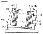
- Fig. 1 is a side view of a flat glasses receiving body suggested in the above JP Laid-open patent.
- a loading surface(14a) for loading flat glasses(G) in vertical direction and a backplate surface(14b) extended in vertical, direction from a rear end portion of the loading surface are formed on an 'L'-shaped support. Since the loading surface is sloped at 2 to 20 degrees toward the backplate surface, a lot of flat glasses(G) is loaded, being lifted up as leaning against the backplate surface(14b).
- estranging members(15) put on rim portions only of the stacked flat glasses are inserted between the rim portions of each flag glass(G) and each flat glass.
- Reinforcing plates(16,17) are disposed on an external side of flat glasses located in a front line and between flat glasses located in a last line and the backplate surface(14b).
- the estranging members(15) are put between the flat glasses(G) and the reinforcing plates, thereby preventing the flat glasses from being polluted and damaged.
- the flat glasses(G) when transferring the flat glasses(G), it is transferred while being sealed with the packing bag(20) or being covered with another box thereon. Then, the loaded glasses are unloaded by releasing the rubber band after loosening the box and the packing bag.
- the present invention provides a packing container and a packing method for flat display glass to improve working efficiency without individually managing a packing material by forming the packing material for packing loaded flat display glass in combined type, cutting down cost by remarkably reducing the number of necessary workers without obtaining another space for loading the packing material.
- a packing container for flat display glass in accordance with the present invention is a packing container for flat display glass for vertically loading and packing a lot of flat display glass, comprising: a loading frame forming a basic bone structure of the packing container for the flat display glass, and consisting of a loading surface formed to support lower ends of each loaded flat display glass and a backplate surface formed vertical to the loading surface on a rear end portion of the loading surface and supporting back sides of each flat display glass; flat glasses fixing devices for fixing the loaded flat display glass; and a combined packing material opening/shutting an opened space of the loading frame where the loaded flat display glass are exposed, in combination with the loading frame as one to be fixed and opened/shut.
- buffer materials for protecting the flat display glass are further comprised on inner sides of lateral walls of the loading frame, formed by connecting an upper side of the loading surface, a front side of the backplate surface, and both side ends of the backplate surface and the loading surface.
- the flat glasses fixing devices consist of a clamp, or one pair of elastic belts on the left and the right and coupling units for reciprocal coupling on one unfixed end of each belt.
- the combined packing material consists of a shutter roll installed on a back side of the loading frame, a shutter rail formed in side wall of the loading frame by connecting both side ends of the backplate surface and the loading surface, as a predetermined groove up to the loading surface from the backplate surface, and a shutter whose first end portion, which is one end, is fixed by being wound and the second end portion, which is the rest end, opens/shuts an opened upper side and a front side of the loading frame as vertically moving along the shutter rail.
- the combined packing material can be closely adhered to side wall of the loading frame formed by connecting both side ends of the backplate surface and the loading surface.
- Many cylinder-shaped rollers are installed on an upper end and a lower end of left and right side walls, respectively.
- a series of both chains rotate in vertical direction as being wound around rollers, covering a front and a rear of the backplate surface by being wound between the rollers on inner sides of both lateral walls of many cylinder-shaped roller loading frames installed on an upper end and a lower end of both lateral walls, respectively.
- Many shutter plates are also comprised to cover at least the opened upper side and the front side of the loading frame, being closely adhered to each other while both side ends thereof are fixed into the both chains. It is possible to form opened part pierced vertically in order that the both chains and the shutter plates can pass through the front end portion of the loading surface.
- a packing method for flat display glass in accordance with the present invention is a packing method for flat display glass for loading and packing a lot of flat display glass into a packing container for the flat display glass, which has: a loading frame consisting of a loading surface formed to support lower ends of each flat display glass and a backplate surface formed vertical to the loading surface and supporting back sides of each flat display glass, and sloped at a predetermined angle toward a back direction when a combination of the loading surface and the backplate surface configures an 'L' shape; flat glasses fixing devices for fixing the loaded flat display glass; and a combined packing material opening/shutting an opened space of the loading frame in combination with the loading frame as one to be opened/shut.
- the method comprising the steps of: a first step of loading each flat display glass into a loading frame; a second step of loading a stiffener into a front side of flat display glass loaded into a front line among the loaded flat display glass; a third step of fixing the loaded flat display glass and the stiffener with flat glasses fixing devices; and a fourth step of packing the loaded flat display glass by cutting off the opened space of the loading frame after shutting the combined packing material.
- the first step includes a 1-1 step of loading an estranging material between the loaded flat display glass.
- the fourth step includes: a 4-1 step of cutting off an opened upper side and a front side of the loading frame by shutting, along a shutter rail, a shutter whose one end is fixed by being wound around the shutter roll installed on a back side of the loading frame and the rest end is tied to a shutter rail formed as a predetermined groove up to the loading surface from the backplate surface on an inner side of a lateral wall of the loading frame, formed by connecting both side ends of the backplate surface and the loading surface; and a 4-2 step of cutting off the opened upper side and the front side of the loading frame with many shutter plates by rotating a rolling shutter consisting of both chains rotating in vertical direction, being installed as covering the backplate surface on inner sides of lateral walls of the loading frame formed by connecting both side ends of the backplate surface and the loading surface, and many shutter plates covering at least the opened upper side and the front side of the loading frame, being closely adhered to each other while fixed into the both chains.
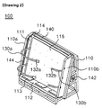
- Fig. 2 is a perspective view of a packing container for flat display glass in accordance with the present invention.
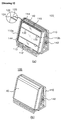
- Fig. 3 is a using state diagram of a packing container for flat display glass in accordance with the present invention
- Fig. 3(a) is a diagram illustrating a state of loading flat display glass into a packing container for the flat display glass in accordance with the present invention
- Fig. 3(b) is a diagram illustrating a state of shutting a shutter of a packing container for flat display glass after loading the flat display glass.
- the packing container for the flat display glass in accordance with the present invention will be described as follows in reference to Fig. 2 and Fig. 3.
- a packing container(100) for flat display glass in accordance with the present invention comprises: a loading frame(110) forming a basic bone structure of the container, and consisting of a loading surface(112) formed in horizontal direction and a backplate surface(114) formed vertical to the loading surface; a stiffener(124) disposed on a front side of flat display glass loaded into a front line to protect loaded flat display glass(120); flat glasses fixing devices(130a,130b) for fixing the loaded flat display glass(120); and a shutter(140) for protecting the loaded flat display glass from an external impact.
- the loading frame(110) in accordance with the present invention forms the basic bone structure of the packing container(100) for the flat display glass, forming the loading surface(112) on a lower end in horizontal direction and the backplate surface(114) in vertical direction.
- the loading surface(112) is a part for supporting lower ends of the flat display glass when loading the flat display glass(120), buffering load of the flat display glass itself and external vibrations or impact by attaching buffer materials(113) to upper sides thereof.
- the backplate surface(114) is a part for supporting back sides of the flat display glass when loading the flat display glass(120), buffering load of the flat display glass itself and external vibrations and impact by attaching a buffer material(115) on front sides thereof.
- a buffer material(111) to inner sides of both lateral walls(110a,110b) of the loading frame(110) protruded toward a front direction by connecting both side ends of the backplate surface(114) and the loading surface(112).
- the buffer materials(113,115) attached to the lateral walls(110a,11b), the loading surface(112), and the backplate surface(114) are detachable for replacement when necessary. So, a contact side of the lateral walls, the loading surface, and the backplate surface as well as one side of the buffer materials can be formed by Velcro fastener.
- the loading surface(112) and the backplate surface(114) are formed in 'L' shape by being vertical to each other, and a combination of the loading surface and the backplate surface is mounted on the loading frame(110). Thus, it is possible to stably load the flat display glass(120) into the loading surface and the backplate surface.
- the stiffener(124) in accordance with the present invention protects the loaded flat display glass(120) from an external impact, being disposed on a front side of flat display glass loaded into a front line among the loaded flat display glass. And, the stiffener(124) ties and fastens the flat glasses fixing devices(130) from a front side of the stiffener when fixing the flat display glass(120), thereby preventing the flat display glass(120) from being impacted or damaged by the flat glasses fixing devices.
- the flat glasses fixing devices(130) in accordance with the present invention fix the loaded flat display glass(120) into the loading frame(110), consisting of one pair of belts(130a,130b) on the left and the right fixed into grooves as one, which are formed on both sides of the backplate surface(114).
- the flat glasses fixing devices(130) fasten the loaded flat display glass(120) as covering it, and are reciprocally coupled on a front side of the stiffener(124) by the coupling units(132). Furthermore, vertically comprise at least more than two flat glasses fixing devices(130) so as to stably fix the loaded flat display glass(120).
- Fig. 2 and Fig. 3 illustrate that the flat glasses fixing devices consist of the one pair of the belts on the left and the right, but unlike this, it is possible to configure them with two belts vertically paired in one, including various types such as supporting bars or clamps except the belts.
- the shutter(140) in accordance with the present invention is a combined packing material for protecting the loaded flat display glass(120) from an external physical impact, and a portion thereof is fixed by being wound around a shutter roll(142) disposed on a back side of the loading frame(110), then is opened/shut along a shutter rail(144). After the shutter(140) is shut, the shutter is fixed by another shutter locking device(not shown), preventing the shutter from being optionally opened.
- the shutter roll(142) is disposed on the back side of the loading frame(110), that is, a space formed on a back side of the backplate surface(114), fixing one end portion of the wound shutter(140) and having a buffer device for stably winding and unwinding the shutter.
- the shutter rail(144) guides a movement of the shutter when opening and shutting the shutter(140), formed as predetermined groove type on inner sides of the both lateral walls(110a,110b) of the loading frame(110) protruded toward a front direction by connecting both side ends of the backplate surface(114) and the loading surface(112).
- a shutter driving roller(not shown) is further comprised on an upper end of the backplate surface(114) so that the shutter can smoothly move, without being hooked, in a part where the shutter is turned toward a front side from the back side of the loading frame(110) when opening/shutting the shutter(140) along the shutter rail(144). Accordingly, it is possible to smoothly open and shut the shutter(140) by the shutter driving roller, supporting load of the shutter and preventing the shutter from sagging.
- the shutter locking device(not shown) prevents the shutter from being optionally opened after shutting the shutter(140), fixing the shutter in a front end portion of the loading surface(112). So, form a hooking end protruded in predetermined size from one end portion of the shutter(140) contacted with the loading surface(112), and comprise tying units for tying to the hooking end like a hook on a front end of the loading surface contacted with the shutter.
- Such shutter locking device can be modified in various types. For instance, the shutter can be fixed with magnetism by attaching a magnet to one end portion of the shutter(140) contacted to each other and/or a front end of the loading surface(112).
- Fig. 2 and Fig. 3 illustrate that the shutter(140) is vertically opened/shut by installing the shutter rail(144) in vertical direction
- the shutter can be horizontally opened/shut by vertically installing the shutter roll on the back side of the loading frame(110) and installing the shutter rail on the front end of the loading surface(112) and an upper side of the loading frame.
- a method for loading and transferring flat display glass by using a packing container for the flat display glass in accordance with the present invention will be described as follows.
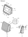
- Fig. 4 is a using state diagram of another embodiment of a packing container for flat display glass in accordance with the present invention
- Fig. 4(a) is a diagram illustrating a state of loading flat display glass in another embodiment of a packing container for the flat display glass in accordance with the present invention
- Fig. 4(b) is a diagram illustrating a state of shutting a rolling shutter after loading flat display glass
- Fig. 4(c) is a sectional view of A-A' direction in accordance another embodiment of the packing container for the flat display glass illustrated in Fig. 4(b).
- FIG. 4(c) have a rolling shutter(150) opening/shutting an opened region of a loading frame as rotating along the loading frame(110) instead of a vertically opened/shut shutter(140).
- FIG. 4(a) through Fig. 4(c) will describe another embodiment of the container, but will omit descriptions on components already described through Fig. 2 and Fig. 3.
- FIG. 4(a) and Fig. 4(b) another embodiment of a packing container(100) for flat display glass in accordance with the present invention has the rolling shutter(150) to protect loaded flat display glass(120) from an external impact by opening/shutting an opened front side and an upper side of a loading frame(110).
- the rolling shutter(150) is installed as sequentially covering a backplate surface(114) toward inner sides of both lateral walls(110a,110b) of the loading frame(110), forming a basic bone structure by comprising a serial of reciprocally connected chains(154) on the left and the right.
- both chains(154) install the both chains(154) to be closely adhered to the inner sides of the both lateral walls(110a,110b) of the loading frame(110) as possible, and give enough margins between the chains and loading regions of the flat display glass so as to prevent the chains(154) from being contacted with or hooked over when loading or unloading the flat display glass(120).
- the rolling shutter(150) pierces through the loading surface since it should freely move in vertical direction while being connected with each other.
- the rolling shutter(150) cannot be hooked over the opened part(158)
- form both widths of the opened part at least equally to those of the rolling shutter(150), and form front/rear widths thereof at least added thickness of the shutter plates(152) and the chains(154).
- a method for loading and transferring flat display glass by using another embodiment of a packing container for the flat display glass in accordance with the present invention will be described as follows.
- a worker can transfer the glasses after cutting off the opened region of the loading frame by rotating the rolling shutter(150) to make the side, where the shutter plates(152) are mounted, toward the front side of the loading frame(110).
- a packing container and a packing method for flat display glass in accordance with the present invention can safely and efficiently perform loading and packing processes of the flat display glass by combining a loading frame for loading the flat display glass with a packing material for packing the loaded flat display glass.
- the packing container and the packing method for the flat display glass in accordance with the present invention have the benefits as follows:
Landscapes
- Engineering & Computer Science (AREA)
- Mechanical Engineering (AREA)
- Packaging Frangible Articles (AREA)
- Pallets (AREA)
- Packaging Of Machine Parts And Wound Products (AREA)
Applications Claiming Priority (2)
| Application Number | Priority Date | Filing Date | Title |
|---|---|---|---|
| KR2003083780 | 2003-11-24 | ||
| KR10-2003-0083780A KR100438200B1 (ko) | 2003-11-24 | 2003-11-24 | 디스플레이용 평판유리 포장 콘테이너 및 포장방법 |
Publications (2)
| Publication Number | Publication Date |
|---|---|
| EP1533250A1 true EP1533250A1 (de) | 2005-05-25 |
| EP1533250B1 EP1533250B1 (de) | 2007-11-21 |
Family
ID=34431820
Family Applications (1)
| Application Number | Title | Priority Date | Filing Date |
|---|---|---|---|
| EP03029688A Expired - Lifetime EP1533250B1 (de) | 2003-11-24 | 2003-12-23 | Verpackungsbehälter und Verpackungsverfahren für Flachbildschirmscheiben |
Country Status (6)
| Country | Link |
|---|---|
| EP (1) | EP1533250B1 (de) |
| JP (1) | JP3643838B1 (de) |
| KR (1) | KR100438200B1 (de) |
| CN (1) | CN100345737C (de) |
| DE (1) | DE60317683T2 (de) |
| TW (1) | TWI272890B (de) |
Cited By (5)
| Publication number | Priority date | Publication date | Assignee | Title |
|---|---|---|---|---|
| WO2007014096A3 (en) * | 2005-07-22 | 2007-05-31 | Corning Inc | Restraining dense packaging system for lcd glass sheets |
| US7686550B2 (en) | 2006-12-21 | 2010-03-30 | Corning Incorporated | Container for packaging and transporting glass sheet(s) |
| US7958999B2 (en) | 2006-12-07 | 2011-06-14 | Nippon Electric Glass Co., Ltd. | Pallet for packing glass plate and glass plate packing unit |
| US7980397B2 (en) | 2006-12-07 | 2011-07-19 | Nippon Electric Glass Co., Ltd. | Glass plate packaging pallet and glass plate package body |
| CN105620945A (zh) * | 2014-11-07 | 2016-06-01 | 青岛富润玻璃有限公司 | 一种上片机的除尘防黏连玻璃架 |
Families Citing this family (16)
| Publication number | Priority date | Publication date | Assignee | Title |
|---|---|---|---|---|
| KR101364947B1 (ko) * | 2006-07-21 | 2014-02-19 | 아사히 가라스 가부시키가이샤 | 판상체의 수납 방법 및 수납 장치 |
| KR100777655B1 (ko) * | 2006-09-18 | 2007-11-21 | (주)천하테크 | 패널적치장치 |
| KR100817942B1 (ko) * | 2006-10-02 | 2008-03-31 | 창선이엔지 주식회사 | 패널 적재용 팔레트 |
| JP2009057051A (ja) * | 2007-08-29 | 2009-03-19 | Nippon Electric Glass Co Ltd | ガラス板梱包体 |
| JP2010280426A (ja) * | 2009-06-08 | 2010-12-16 | Avanstrate Taiwan Inc | ガラス板梱包用パレット |
| JP5489088B2 (ja) * | 2010-04-28 | 2014-05-14 | 旭硝子株式会社 | ガラス板梱包体及びガラス板積層体の梱包方法 |
| CN102774575B (zh) * | 2012-08-09 | 2015-04-29 | 天津南玻节能玻璃有限公司 | 一种玻璃包装方法 |
| JP2014108823A (ja) * | 2012-12-04 | 2014-06-12 | Nippon Electric Glass Co Ltd | ガラス板梱包用パレットおよびガラス板梱包体 |
| CN103693092B (zh) * | 2013-12-11 | 2016-05-04 | 芜湖欣荣管业科技有限公司 | 一种吊架式平板玻璃周转车 |
| KR101590563B1 (ko) * | 2014-08-04 | 2016-02-18 | (주)젠틸패키징시스템 | 크레이트의 글라스패널 커버장치 |
| CN105151521A (zh) * | 2015-09-29 | 2015-12-16 | 重庆市合川区华丰包装有限公司 | 玻璃成品包装架 |
| KR102612456B1 (ko) * | 2015-10-19 | 2023-12-11 | 코닝정밀소재 주식회사 | 유리기판 운송용 구조물 및 운송 방법 |
| CN109507818B (zh) * | 2019-01-04 | 2021-06-01 | 深圳市华星光电半导体显示技术有限公司 | 拔片工具 |
| CN112591463B (zh) * | 2020-12-16 | 2022-08-30 | 彩虹(合肥)液晶玻璃有限公司 | 一种a型架定位安装结构 |
| JPWO2023042653A1 (de) * | 2021-09-17 | 2023-03-23 | ||
| CN114873061B (zh) * | 2022-07-05 | 2022-09-27 | 山东中宏路桥建设有限公司 | 一种建筑用玻璃运输架 |
Citations (4)
| Publication number | Priority date | Publication date | Assignee | Title |
|---|---|---|---|---|
| DE8107930U1 (de) * | 1981-03-18 | 1981-07-09 | HEGLA Fahrzeug- und Maschinenbau GmbH & Co KG, 3472 Beverungen | Transportgestell fuer flaechige Gegenstaende |
| US5678693A (en) * | 1996-07-26 | 1997-10-21 | Dale Tapp | Glass storage safe |
| JP2000203679A (ja) * | 1998-11-13 | 2000-07-25 | Nippon Electric Glass Co Ltd | ガラス板の収納方法 |
| US20030164318A1 (en) * | 2001-08-10 | 2003-09-04 | Ipl Inc. | Crate for carrying glass panels |
Family Cites Families (6)
| Publication number | Priority date | Publication date | Assignee | Title |
|---|---|---|---|---|
| DE3621988C1 (de) * | 1986-07-01 | 1987-05-14 | Flachglas Ag | Transportgestell fuer Glasscheiben |
| JPS6344482A (ja) * | 1986-07-31 | 1988-02-25 | 日綜産業株式会社 | 折り畳み自在なコンテナ |
| JP3260445B2 (ja) * | 1992-10-08 | 2002-02-25 | 日本板硝子株式会社 | ガラス板等の大型板状物の荷役用保持具 |
| CN2219343Y (zh) * | 1994-11-19 | 1996-02-07 | 周德阳 | 组合式箱体 |
| JP3429664B2 (ja) * | 1997-05-27 | 2003-07-22 | セントラル硝子株式会社 | パレットに積載した板状体の固定方法および固定具 |
| JP2003137287A (ja) * | 2001-10-31 | 2003-05-14 | Nippon Sheet Glass Co Ltd | 板状物用梱包具 |
-
2003
- 2003-11-24 KR KR10-2003-0083780A patent/KR100438200B1/ko not_active Expired - Lifetime
- 2003-12-23 DE DE60317683T patent/DE60317683T2/de not_active Expired - Lifetime
- 2003-12-23 TW TW092136498A patent/TWI272890B/zh not_active IP Right Cessation
- 2003-12-23 EP EP03029688A patent/EP1533250B1/de not_active Expired - Lifetime
- 2003-12-24 JP JP2003427756A patent/JP3643838B1/ja not_active Expired - Lifetime
- 2003-12-29 CN CNB2003101215996A patent/CN100345737C/zh not_active Expired - Lifetime
Patent Citations (4)
| Publication number | Priority date | Publication date | Assignee | Title |
|---|---|---|---|---|
| DE8107930U1 (de) * | 1981-03-18 | 1981-07-09 | HEGLA Fahrzeug- und Maschinenbau GmbH & Co KG, 3472 Beverungen | Transportgestell fuer flaechige Gegenstaende |
| US5678693A (en) * | 1996-07-26 | 1997-10-21 | Dale Tapp | Glass storage safe |
| JP2000203679A (ja) * | 1998-11-13 | 2000-07-25 | Nippon Electric Glass Co Ltd | ガラス板の収納方法 |
| US20030164318A1 (en) * | 2001-08-10 | 2003-09-04 | Ipl Inc. | Crate for carrying glass panels |
Non-Patent Citations (1)
| Title |
|---|
| PATENT ABSTRACTS OF JAPAN vol. 2000, no. 10 17 November 2000 (2000-11-17) * |
Cited By (5)
| Publication number | Priority date | Publication date | Assignee | Title |
|---|---|---|---|---|
| WO2007014096A3 (en) * | 2005-07-22 | 2007-05-31 | Corning Inc | Restraining dense packaging system for lcd glass sheets |
| US7958999B2 (en) | 2006-12-07 | 2011-06-14 | Nippon Electric Glass Co., Ltd. | Pallet for packing glass plate and glass plate packing unit |
| US7980397B2 (en) | 2006-12-07 | 2011-07-19 | Nippon Electric Glass Co., Ltd. | Glass plate packaging pallet and glass plate package body |
| US7686550B2 (en) | 2006-12-21 | 2010-03-30 | Corning Incorporated | Container for packaging and transporting glass sheet(s) |
| CN105620945A (zh) * | 2014-11-07 | 2016-06-01 | 青岛富润玻璃有限公司 | 一种上片机的除尘防黏连玻璃架 |
Also Published As
| Publication number | Publication date |
|---|---|
| TW200421963A (en) | 2004-10-16 |
| CN1621324A (zh) | 2005-06-01 |
| JP2005153988A (ja) | 2005-06-16 |
| EP1533250B1 (de) | 2007-11-21 |
| KR20040037019A (ko) | 2004-05-04 |
| TWI272890B (en) | 2007-02-01 |
| KR100438200B1 (ko) | 2004-07-02 |
| CN100345737C (zh) | 2007-10-31 |
| JP3643838B1 (ja) | 2005-04-27 |
| DE60317683D1 (de) | 2008-01-03 |
| DE60317683T2 (de) | 2008-09-25 |
Similar Documents
| Publication | Publication Date | Title |
|---|---|---|
| EP1533250B1 (de) | Verpackungsbehälter und Verpackungsverfahren für Flachbildschirmscheiben | |
| CN101568480B (zh) | 包装和运输玻璃板的容器 | |
| EP1533251B1 (de) | Verpackungsbehälter für Flachbildschirmscheibe | |
| CN100540414C (zh) | 显示器用平面玻璃板的包装箱-ⅰ | |
| TWI590998B (zh) | Sheet glass winding device and storage device | |
| US20010042603A1 (en) | Rolled screen drawer | |
| TWI831872B (zh) | 被捆包體及捆包體 | |
| TW200523186A (en) | Glass plate packaging box, packaging method and package-opening method | |
| TWI361299B (en) | Restraining dense packaging system for lcd glass sheets | |
| KR20190060670A (ko) | 테이프 롤 및 테이프 마운터 | |
| WO2012005105A1 (ja) | 板状体の梱包構造及び板状体搬送方法 | |
| JP4793119B2 (ja) | ガラス板輸送用パレット | |
| CN109421976B (zh) | 容器处理设备 | |
| JP2007153353A (ja) | 板状物品収容ケース及び板状物品移送用台車及びこれらを用いた光学表示装置の製造方法 | |
| KR20050022963A (ko) | 디스플레이용 평판유리 포장 콘테이너 | |
| KR20210008492A (ko) | 유리 롤 곤포체, 및 그 제작 방법 | |
| JP3493236B2 (ja) | アスパラガス等長尺青果物の結束機 | |
| AU2017245386A1 (en) | Liner for Container | |
| CN1688482A (zh) | 用于装载袋子串的设备和方法 | |
| US20090242146A1 (en) | Modular drum | |
| JP4286210B2 (ja) | ガラス基板の搬送方法および搬送システム | |
| KR20140007555A (ko) | 레티클 케이스 | |
| CN213385430U (zh) | 光伏组件防倒包装 | |
| JP2004196404A (ja) | 荷崩れ防止装置 | |
| JP3068656U (ja) | シ―ト式車両用荷下ろし装置 |
Legal Events
| Date | Code | Title | Description |
|---|---|---|---|
| PUAI | Public reference made under article 153(3) epc to a published international application that has entered the european phase |
Free format text: ORIGINAL CODE: 0009012 |
|
| AK | Designated contracting states |
Kind code of ref document: A1 Designated state(s): AT BE BG CH CY CZ DE DK EE ES FI FR GB GR HU IE IT LI LU MC NL PT RO SE SI SK TR |
|
| AX | Request for extension of the european patent |
Extension state: AL LT LV MK |
|
| 17P | Request for examination filed |
Effective date: 20051125 |
|
| AKX | Designation fees paid |
Designated state(s): DE FR GB |
|
| GRAP | Despatch of communication of intention to grant a patent |
Free format text: ORIGINAL CODE: EPIDOSNIGR1 |
|
| GRAS | Grant fee paid |
Free format text: ORIGINAL CODE: EPIDOSNIGR3 |
|
| GRAA | (expected) grant |
Free format text: ORIGINAL CODE: 0009210 |
|
| AK | Designated contracting states |
Kind code of ref document: B1 Designated state(s): DE FR GB |
|
| REG | Reference to a national code |
Ref country code: GB Ref legal event code: FG4D |
|
| REF | Corresponds to: |
Ref document number: 60317683 Country of ref document: DE Date of ref document: 20080103 Kind code of ref document: P |
|
| ET | Fr: translation filed | ||
| PLBE | No opposition filed within time limit |
Free format text: ORIGINAL CODE: 0009261 |
|
| STAA | Information on the status of an ep patent application or granted ep patent |
Free format text: STATUS: NO OPPOSITION FILED WITHIN TIME LIMIT |
|
| 26N | No opposition filed |
Effective date: 20080822 |
|
| PG25 | Lapsed in a contracting state [announced via postgrant information from national office to epo] |
Ref country code: FR Free format text: LAPSE BECAUSE OF NON-PAYMENT OF DUE FEES Effective date: 20091231 |
|
| REG | Reference to a national code |
Ref country code: FR Ref legal event code: CD |
|
| REG | Reference to a national code |
Ref country code: DE Ref legal event code: R081 Ref document number: 60317683 Country of ref document: DE Owner name: SAMSUNG CORNING PRECISION MATERIALS CO., LTD.,, KR Free format text: FORMER OWNER: SAMSUNG CORNING PRECISION GLASS CO. LTD., KYUNGSANGBUK, KR Effective date: 20110201 Ref country code: DE Ref legal event code: R081 Ref document number: 60317683 Country of ref document: DE Owner name: CORNING PRECISION MATERIALS CO., LTD., ASAN-SI, KR Free format text: FORMER OWNER: SAMSUNG CORNING PRECISION GLASS CO. LTD., KYUNGSANGBUK, KR Effective date: 20110201 |
|
| REG | Reference to a national code |
Ref country code: FR Ref legal event code: CD Owner name: CORNING PRECISION MATERIALS CO., LTD., KR Effective date: 20140924 |
|
| REG | Reference to a national code |
Ref country code: FR Ref legal event code: TP Owner name: CORNING PRECISION MATERIALS CO., LTD., KR Effective date: 20140926 |
|
| REG | Reference to a national code |
Ref country code: FR Ref legal event code: CD Owner name: CORNING PRECISION MATERIALS CO., LTD., KR Effective date: 20150112 |
|
| REG | Reference to a national code |
Ref country code: DE Ref legal event code: R082 Ref document number: 60317683 Country of ref document: DE Representative=s name: GULDE & PARTNER PATENT- UND RECHTSANWALTSKANZL, DE Ref country code: DE Ref legal event code: R082 Ref document number: 60317683 Country of ref document: DE Ref country code: DE Ref legal event code: R082 Ref document number: 60317683 Country of ref document: DE Representative=s name: BUNGARTZ CHRISTOPHERSEN PARTNERSCHAFT MBB PATE, DE |
|
| REG | Reference to a national code |
Ref country code: DE Ref legal event code: R082 Ref document number: 60317683 Country of ref document: DE Representative=s name: BUNGARTZ CHRISTOPHERSEN PARTNERSCHAFT MBB PATE, DE Ref country code: DE Ref legal event code: R082 Ref document number: 60317683 Country of ref document: DE Ref country code: DE Ref legal event code: R081 Ref document number: 60317683 Country of ref document: DE Owner name: CORNING PRECISION MATERIALS CO., LTD., ASAN-SI, KR Free format text: FORMER OWNER: SAMSUNG CORNING PRECISION MATERIALS CO., LTD., GUMI, GYEONGSANGBUK, KR |
|
| REG | Reference to a national code |
Ref country code: DE Ref legal event code: R082 Ref document number: 60317683 Country of ref document: DE |
|
| REG | Reference to a national code |
Ref country code: FR Ref legal event code: PLFP Year of fee payment: 13 |
|
| REG | Reference to a national code |
Ref country code: FR Ref legal event code: PLFP Year of fee payment: 14 |
|
| REG | Reference to a national code |
Ref country code: FR Ref legal event code: PLFP Year of fee payment: 15 |
|
| REG | Reference to a national code |
Ref country code: FR Ref legal event code: PLFP Year of fee payment: 16 |
|
| PG25 | Lapsed in a contracting state [announced via postgrant information from national office to epo] |
Ref country code: FR Free format text: LAPSE BECAUSE OF NON-PAYMENT OF DUE FEES Effective date: 20091231 |
|
| PGRI | Patent reinstated in contracting state [announced from national office to epo] |
Ref country code: FR Effective date: 20101206 |
|
| PGFP | Annual fee paid to national office [announced via postgrant information from national office to epo] |
Ref country code: FR Payment date: 20220920 Year of fee payment: 20 |
|
| PGFP | Annual fee paid to national office [announced via postgrant information from national office to epo] |
Ref country code: GB Payment date: 20221005 Year of fee payment: 20 Ref country code: DE Payment date: 20220920 Year of fee payment: 20 |
|
| REG | Reference to a national code |
Ref country code: DE Ref legal event code: R071 Ref document number: 60317683 Country of ref document: DE |
|
| REG | Reference to a national code |
Ref country code: GB Ref legal event code: PE20 Expiry date: 20231222 |
|
| PG25 | Lapsed in a contracting state [announced via postgrant information from national office to epo] |
Ref country code: GB Free format text: LAPSE BECAUSE OF EXPIRATION OF PROTECTION Effective date: 20231222 |
|
| PG25 | Lapsed in a contracting state [announced via postgrant information from national office to epo] |
Ref country code: GB Free format text: LAPSE BECAUSE OF EXPIRATION OF PROTECTION Effective date: 20231222 |