EP1533251B1 - Verpackungsbehälter für Flachbildschirmscheibe - Google Patents
Verpackungsbehälter für Flachbildschirmscheibe Download PDFInfo
- Publication number
- EP1533251B1 EP1533251B1 EP20040027838 EP04027838A EP1533251B1 EP 1533251 B1 EP1533251 B1 EP 1533251B1 EP 20040027838 EP20040027838 EP 20040027838 EP 04027838 A EP04027838 A EP 04027838A EP 1533251 B1 EP1533251 B1 EP 1533251B1
- Authority
- EP
- European Patent Office
- Prior art keywords
- gear
- bar
- plate body
- flat display
- section
- Prior art date
- Legal status (The legal status is an assumption and is not a legal conclusion. Google has not performed a legal analysis and makes no representation as to the accuracy of the status listed.)
- Expired - Lifetime
Links
Images



Classifications
-
- B—PERFORMING OPERATIONS; TRANSPORTING
- B65—CONVEYING; PACKING; STORING; HANDLING THIN OR FILAMENTARY MATERIAL
- B65G—TRANSPORT OR STORAGE DEVICES, e.g. CONVEYORS FOR LOADING OR TIPPING, SHOP CONVEYOR SYSTEMS OR PNEUMATIC TUBE CONVEYORS
- B65G49/00—Conveying systems characterised by their application for specified purposes not otherwise provided for
- B65G49/05—Conveying systems characterised by their application for specified purposes not otherwise provided for for fragile or damageable materials or articles
- B65G49/06—Conveying systems characterised by their application for specified purposes not otherwise provided for for fragile or damageable materials or articles for fragile sheets, e.g. glass
- B65G49/062—Easels, stands or shelves, e.g. castor-shelves, supporting means on vehicles
-
- B—PERFORMING OPERATIONS; TRANSPORTING
- B65—CONVEYING; PACKING; STORING; HANDLING THIN OR FILAMENTARY MATERIAL
- B65D—CONTAINERS FOR STORAGE OR TRANSPORT OF ARTICLES OR MATERIALS, e.g. BAGS, BARRELS, BOTTLES, BOXES, CANS, CARTONS, CRATES, DRUMS, JARS, TANKS, HOPPERS, FORWARDING CONTAINERS; ACCESSORIES, CLOSURES, OR FITTINGS THEREFOR; PACKAGING ELEMENTS; PACKAGES
- B65D85/00—Containers, packaging elements or packages, specially adapted for particular articles or materials
- B65D85/30—Containers, packaging elements or packages, specially adapted for particular articles or materials for articles particularly sensitive to damage by shock or pressure
- B65D85/48—Containers, packaging elements or packages, specially adapted for particular articles or materials for articles particularly sensitive to damage by shock or pressure for glass sheets
Definitions
- a first insertion hole is comprised, in which a sidewall is pierced on the right and left sides in predetermined diameter on a horizontal extending line of the second bar, and the adjusting member further comprises a first lever whose one section is tied to the second section of the second bar by being inserted into the first insertion hole and rotating the second bar by transmitting a rotational force to the second bar with an outer force.
- each alignment further comprises at least one supporting member whose first section is fixed to the second side of the plate body and a second section is tied to inner sides of sidewalls to support the plate body, thereby maintaining a parallel state between the plate body and the sidewalls.
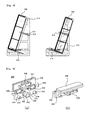
- each alignment is composed of: a plate body configured in flat plate shape, and whose first side is mounted as maintaining a parallel state with a lower side of the loading surface; and an adjusting member inserted into a first insertion hole of the plate body, and in which a first section thereof is fixed to the lower side of the loading surface to finely adjust a horizontal position of the plate body; and wherein the plate body is divided into a lower area and an upper surface area by a horizontal extending line of the loading surface, and a first insertion hole pierced on the right and left sides is comprised in the lower area.
- the plate body consists of: a first plate body whose first side is parallel to the lower side of the loading surface, the first plate body being mounted under the horizontal extending line of the loading surface, and the first plate body including the first insertion hole; a second plate body exposed to a top of the horizontal extending line of the loading surface by being mounted in an upper section of the first plate body, and in which a first side of the second plate body is closely adhered to one side of a flat display glass; and hinges fixed to a second side, an opposite side of the first side of the first plate body and the second plate body, and the hinges foldably connecting the first plate body with the second plate body. Then, the second plate body is folded in a direction opposite to the loading surface.
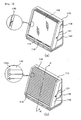
- the shutter plates(142) in accordance with the present invention are in long and thin piece shape, being mounted in certain areas of the right/left chains(144) to cover an open area of the loading frame(110).
- the shutter plates(142) are comprised in plural to sufficiently cover front surface and upper surface areas of the loading frame(110), and each shutter plate is closely disposed to each other while both sections thereof are fixed to the right/left chains(144).
- both sections of each shutter plate(142) should be fixed to the chains(144) by using coupling means(142a) such as screws.
- the rolling shutter(140) passes through a loading surface(112) to freely move in vertical direction while being connected to each other. Accordingly, a pierced hole(118) is formed in a front section of the loading surface(112) such that the rolling shutter(140) can pass through.
- a right/left width of the pierced hole is formed to be at least identical with a width of the rolling shutter(140), and a front/rear width thereof is formed to be at least identical with the added thickness of the shutter plates(142) and the chains(144).
- an outer force should be transmitted to the first gear to rotate the first gear(148).
- the outer force is generated by a user or a predetermined motor. That is to say, the user rotates the first gear(148) by using a predetermined second lever(not shown) or rotates the first gear with the motor by connecting a driving shaft of the motor(not shown) with the first gear. So, a second insertion hole(149) pierced on the right and the left in predetermined diameter should be formed in a horizontal extending line of the first gear(148) of the one sidewall(116).
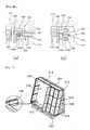
- the first rail portions(216) are formed in positions spaced from the right/left sections of the loading surface(212) at certain intervals, and are formed on at least more outer sides than the right/left alignments.
- the right/left side doors(256) are disposed as covering the outside of the right/left alignments(230).
- the adjusting bar finely moves on the right and the left along the screw grooves by the adjusting pipe being turned, and the first plate body(232) also moves on the right and the left.
Landscapes
- Engineering & Computer Science (AREA)
- Mechanical Engineering (AREA)
- Packaging Frangible Articles (AREA)
- Pallets (AREA)
- Devices For Indicating Variable Information By Combining Individual Elements (AREA)
Claims (11)
- Verpackungsbehälter für flaches Displayglas zum vertikalen Aufladen und Verpacken von mehreren flachen Displaygläsern, der Folgendes umfasst:ein Ladegestell, das die genannten flachen Displaygläser aufnimmt, wobei das genannte Ladegestell Folgendes umfasst:eine Ladefläche (112), die untere Enden der jeweiligen aufgeladenen flachen Displaygläser trägt,eine Rückplattenfläche (114), die in einem hinteren Teil der Ladefläche (112) so ausgebildet ist, dass sie zur genannten Ladefläche (112) vertikal ist, wobei die genannte Rückplattenfläche (114) Rückseiten flacher Displaygläser trägt,rechte/linke Seitenwände (116), die so konfiguriert sind, dass sie beide Seitenenden der genannten Rückplattenfläche (114) und der genannten Ladefläche (112) verbinden, wobei der Verpackungsbehälter dadurch gekennzeichnet ist, dass:ein erstes Einfügungsloch (137), wobei das erste Einfügungsloch in die rechten/linken Seitenwände (116) mit einem vorbestimmten Durchmesser gebohrt ist,rechte/linke Ausrichtungsvorrichtungen (130), die sich auf Innenseiten der genannten rechten/linken Seitenwände (116) befinden, wobei die genannten rechten/linken Ausrichtungsvorrichtungen (130) einen ersten Hebel (136) haben, wobei der genannte erste Hebel (136) in das erste Einfügungsloch (137) eingesetzt ist und die genannten rechten/linken Ausrichtungsvorrichtungen beide Seiten der genannten aufgeladenen flachen Displaygläser fixieren und stützen, indem horizontale Positionen der genannten rechten/linken Ausrichtungsvorrichtungen reguliert werden, wobei die horizontalen Positionen der genannten rechten/linken Ausrichtungsvorrichtungen durch Drehen des genannten ersten Hebels (136) durch das erste Einfügungsloch reguliert werden, undein Öffnungs-/Schließelement (140), das einen offenen oberen Oberflächenbereich und einen offenen vorderen Oberflächenbereich des genannten Ladegestells öffnet und schließt.
- Verpackungsbehälter nach Anspruch 1, wobei jede Ausrichtungsvorrichtung (130) Folgendes umfasst:einen Plattenkörper (132), der eine flache Plattengestalt aufweist, wobei eine erste Seite des genannten Plattenkörpers eng an einer Seite der genannten flachen Displaygläser (120) anliegt, während gleichzeitig ein Parallelzustand zwischen dem genannten Plattenkörper (132) und den genannten rechten/linken Seitenwänden (116) beibehalten wird, undein Einstellelement, das an einer zweiten Seite des genannten Plattenkörpers (132) befestigt ist, wobei die genannte zweite Seite des genannten Plattenkörpers (132) eine zur genannten ersten Seite des genannten Plattenkörpers entgegengesetzte Seite ist und das genannte Einstellelement eine horizontale Position des genannten Plattenkörpers fein einstellt.
- Verpackungsbehälter nach Anspruch 2, wobei das genannte Einstellelement Folgendes umfasst:einen ersten Stab (134), der eine Stangenform hat, wobei ein erster Teil des genannten ersten Stabs an der genannten zweiten Seite des genannten Plattenkörpers befestigt ist, undeinen zweiten Stab (135), der eine Stangenform hat, wobei ein erster Teil des genannten zweiten Stabs mit einem unbefestigten zweiten Teil des genannten ersten Stabs gekoppelt ist und ein zweiter Teil des genannten zweiten Stabs mit den genannten rechten/linken Seitenwänden (116) im Eingriff verbunden ist; und wobeiSchraubenrillen (134a, 135a) jeweils in einem gekoppelten Stück des genannten ersten Stabs (134) und des genannten zweiten Stabs (135) ausgebildet sind.
- Verpackungsbehälter nach Anspruch 3, wobei das genannte Einstellelement ferner einen ersten Hebel (136) umfasst, wobei ein Teil des genannten ersten Hebels in das genannte erste Einfügungsloch (136) eingefügt ist, wobei ein Teil des genannten ersten Hebels (137) mit dem genannten zweiten Teil des genannten zweiten Stabs (135) verbunden ist und der genannte erste Hebel (136) den genannten zweiten Stab (135) in Drehung versetzt, indem eine durch eine äußere Kraft verursachte Rotationskraft auf den genannten zweiten Stab (135) übertragen wird.
- Verpackungsbehälter nach Anspruch 2, wobei jede Ausrichtungsvorrichtung (130) ferner wenigstens ein Tragelement (138, 139) umfasst, wobei der erste Teil des genannten Tragelements (138, 139) an der genannten zweiten Seite des genannten Plattenkörpers (132) befestigt ist, der zweite Teil des genannten Tragelements (138, 139) mit der genannten Innenseite der genannten rechten/linken Seitenwände (116) verbunden ist und das genannte Tragelement (138, 139) einen Parallelzustand zwischen dem genannten Plattenkörper (132) und den genannten rechten/linken Seitenwänden (116) beibehält, indem das genannte Tragelement (138, 139) den genannten Plattenkörper (132) trägt.
- Verpackungsbehälter nach Anspruch 5, wobei jedes Tragelement (138, 139) Folgendes umfasst:einen Tragstab (138), der eine Stangenform aufweist, wobei ein erster Teil des genannten Tragstabs an der genannten zweiten Seite des Plattenkörpers (132) befestigt ist, undeine Tragröhre (139), wobei die eine Röhrenform aufweisende genannte Tragröhre (139) innen durchbohrt ist, wobei beide Teile offen sind, wobei ein unbefestigter zweiter Teil des genannten Tragstabs (138) in einen offenen ersten Teil der genannten Tragröhre (139) eingefügt ist und ein zweiter Teil der genannten Tragröhre (139) so an der genannten Innenseite der genannten rechten/linken Seitenwände (116) befestigt ist, dass der genannte zweite Teil der genannten Tragröhre (139) von der genannten Innenseite der genannten rechten/linken Seitenwände (116) in bestimmten Abständen beabstandet ist, und wobeieine komplette Länge des genannten Tragelements variiert wird, während sich der genannte Tragstab (132) in horizontaler Richtung entlang der genannten Tragröhre (139) entsprechend der Position des genannten fein eingestellten Plattenkörpers (132) bewegt.
- Verpackungsbehälter nach Anspruch 1, wobei das genannte Öffnungs-/Schließelement (120) Folgendes umfasst:mehrere Rollen (146), die eine Zylinderform aufweisen, wobei sich die genannten Rollen nahe an den genannten Innenseiten der genannten rechten/linken Seitenwände (116) des genannten Ladegestells befinden, wobei die genannten Rollen (146) an einem oberen Ende und einem unteren Ende der genannten rechten/linken Seitenwände (116) in horizontaler Richtung montiert sind,eine Reihe rechter/linker Ketten (144), wobei die genannten rechten/linken Ketten (144) zusammen die jeweiligen Rollen (146) und die genannte Rückplattenfläche (114) abdecken, wobei die genannten rechten/linken Ketten (144) um jeweils einen rechten Teil und einen linken Teil der jeweiligen Rollen (146) gewickelt und daran befestigt sind, wobei die genannten rechten/linken Ketten (144) durch Drehkräfte der jeweiligen Rollen (146) vertikal in Drehung versetzt werden, undmehrere Verschlussplatten (142), die eine Stangenform aufweisen, wobei die genannten Verschlussplatten (142) eng aneinander anliegen, während beide Teile der jeweiligen Verschlussplatten (142) an den rechten/linken Ketten (144) befestigt sind, wobei die genannten Verschlussplatten (142) folglich wenigstens den genannten offenen oberen Oberflächenbereich und den genannten offenen vorderen Oberflächenbereich des genannten Ladegestells bedecken; und wobeiein gebohrtes Loch (118), das vertikal gebohrt ist, so dass die genannten rechten/linken Ketten (144) durchlaufen können, in einem vorderen Teil der genannten Ladefläche (112) enthalten ist.
- Verpackungsbehälter nach Anspruch 7, wobei das genannte Öffnungs-/Verschlusselement (120) ferner Folgendes umfasst:ein erstes Zahnrad (148), das sich innerhalb einer Seitenwand des genannten Ladegestells befindet, wobei das genannte erste Zahnrad (148) eine vertikale Drehkraft durch den Empfang einer äußeren Kraft erzeugt, undein Drehkraftübertragungselement (150), das wenigstens eine der genannten Rollen (146) mit dem genannten ersten Zahnrad (148) zusammenwirken lässt, wobei das genannte Drehkraftüberträgungselement (150) die genannten Rollen (146) in vertikaler Richtung in Drehung versetzt, indem das Drehkraftübertragungselement (150) die genannte vertikale Drehkraft des genannten ersten Zahnrads (148) auf die genannten Rollen (146) überträgt.
- Verpackungsbehälter nach Anspruch 8, wobei das genannte Drehkraftübertragungselement (150) Folgendes umfasst:ein zweites Zahnrad, das in das genannte erste Zahnrad (148) eingreift, wobei das genannte zweite Zahnrad die genannte vertikale Drehkraft des genannten ersten Zahnrads (148) in eine horizontale Drehkraft umwandelt, undein drittes Zahnrad, das in das genannte zweite Zahnrad eingreift, wobei das genannte dritte Zahnrad die genannte horizontale Drehkraft des genannten zweiten Zahnrads in eine vertikale Drehkraft umwandelt, wobei das genannte dritte Zahnrad mit einer der genannten Rollen in Eingriff ist, wobei das genannte dritte Zahnrad die genannte vertikale Drehkraft auf die genannten Rollen überträgt.
- Verpackungsbehälter nach Anspruch 8, wobei das genannte Drehkraftübertragungselement (150) einen Riemen umfasst, der zum Befestigen zwischen einer der genannten Rollen (146) und dem genannten ersten Zahnrad gewickelt ist.
- Verpackungsbehälter nach Anspruch 8, wobei die genannten rechten/linken Seitenwände (116) Folgendes umfassen:ein zweites Einfügungsloch (149), das rechts und links mit einem vorbestimmten Durchmesser auf einer horizontal verlaufenden Linie des genannten ersten Zahnrads (148) gebohrt ist, wobei das genannte Öffnungs-/Schließelement (140) ferner Folgendes umfasst:einen zweiten Hebel, wobei ein Teil des genannten zweiten Hebels in das genannte zweite Einfügungsloch (149) eingefügt ist, wobei der genannte eine Teil des genannten zweiten Hebels mit dem genannten ersten Zahnrad (148) verbunden ist und der genannte zweite Hebel eine durch eine äußere Kraft verursachte Drehkraft auf das genannte erste Zahnrad (148) überträgt.
Priority Applications (1)
| Application Number | Priority Date | Filing Date | Title |
|---|---|---|---|
| EP07117795A EP1884484B1 (de) | 2003-11-24 | 2004-11-24 | Verpackungsbehälter für Flachbildschirmglas |
Applications Claiming Priority (4)
| Application Number | Priority Date | Filing Date | Title |
|---|---|---|---|
| KR10-2003-0083781A KR100438201B1 (ko) | 2003-11-24 | 2003-11-24 | 디스플레이용 평판유리 포장 콘테이너 |
| KR2003083780 | 2003-11-24 | ||
| KR2003083781 | 2003-11-24 | ||
| KR10-2003-0083780A KR100438200B1 (ko) | 2003-11-24 | 2003-11-24 | 디스플레이용 평판유리 포장 콘테이너 및 포장방법 |
Related Child Applications (1)
| Application Number | Title | Priority Date | Filing Date |
|---|---|---|---|
| EP07117795A Division EP1884484B1 (de) | 2003-11-24 | 2004-11-24 | Verpackungsbehälter für Flachbildschirmglas |
Publications (2)
| Publication Number | Publication Date |
|---|---|
| EP1533251A1 EP1533251A1 (de) | 2005-05-25 |
| EP1533251B1 true EP1533251B1 (de) | 2008-09-03 |
Family
ID=34437039
Family Applications (2)
| Application Number | Title | Priority Date | Filing Date |
|---|---|---|---|
| EP20040027838 Expired - Lifetime EP1533251B1 (de) | 2003-11-24 | 2004-11-24 | Verpackungsbehälter für Flachbildschirmscheibe |
| EP07117795A Expired - Lifetime EP1884484B1 (de) | 2003-11-24 | 2004-11-24 | Verpackungsbehälter für Flachbildschirmglas |
Family Applications After (1)
| Application Number | Title | Priority Date | Filing Date |
|---|---|---|---|
| EP07117795A Expired - Lifetime EP1884484B1 (de) | 2003-11-24 | 2004-11-24 | Verpackungsbehälter für Flachbildschirmglas |
Country Status (5)
| Country | Link |
|---|---|
| EP (2) | EP1533251B1 (de) |
| JP (1) | JP3739382B2 (de) |
| CN (1) | CN1314570C (de) |
| DE (2) | DE602004016267D1 (de) |
| TW (1) | TWI261569B (de) |
Families Citing this family (20)
| Publication number | Priority date | Publication date | Assignee | Title |
|---|---|---|---|---|
| US7686550B2 (en) | 2006-12-21 | 2010-03-30 | Corning Incorporated | Container for packaging and transporting glass sheet(s) |
| JP4643683B2 (ja) * | 2008-05-13 | 2011-03-02 | AvanStrate株式会社 | 梱包装置 |
| KR200465373Y1 (ko) | 2011-05-17 | 2013-02-15 | 주식회사 미래엔지니어링 | 엘시디 원판 유리의 밀림 방지 장치 및 이 밀림 방지 장치를 포함하는 엘시디 원판 유리 운반 장치 |
| KR200465374Y1 (ko) | 2011-05-17 | 2013-02-15 | 주식회사 미래엔지니어링 | 커버 고정 장치를 포함하는 엘시디 원판 유리 운반 장치 |
| KR101176034B1 (ko) | 2011-12-21 | 2012-08-24 | 주식회사 코아테크시스템 | 엘시디 글라스 크레이트용 차폐장치 |
| CN102530354A (zh) * | 2011-12-30 | 2012-07-04 | 张家港市环宇制药设备有限公司 | 直立式软袋灭菌托盘 |
| BE1020750A3 (nl) * | 2012-06-12 | 2014-04-01 | Parnass Bv Met Beperkte Aansprakelijheid | Element voor het opslaan, behandelen en transporteren van hoofdzakelijk plaatvormige voorwerpen. |
| KR101385218B1 (ko) * | 2012-08-03 | 2014-04-14 | 삼성코닝정밀소재 주식회사 | 유리기판 반송을 위한 적재 컨테이너 |
| CN103318438B (zh) * | 2013-06-20 | 2015-06-17 | 四川长虹电器股份有限公司 | 平板电视机的倾斜装箱装置 |
| JP6656586B2 (ja) | 2016-02-26 | 2020-03-04 | 日本電気硝子株式会社 | ガラス板梱包用パレット及びガラス板梱包体 |
| CN106185322B (zh) * | 2016-07-28 | 2018-09-28 | 彩虹显示器件股份有限公司 | 一种折叠式a型架 |
| CN107310941A (zh) * | 2017-07-26 | 2017-11-03 | 重庆华瑞玻璃有限公司 | 一种玻璃运输架 |
| CN108106996B (zh) * | 2017-12-25 | 2024-05-28 | 通彩智能科技集团有限公司 | 一种玻璃检测盛放平台 |
| CN110654830B (zh) * | 2019-10-15 | 2024-02-09 | 杭州中为光电技术有限公司 | 兼容不同尺寸硅棒的翻转装置 |
| JP7616575B2 (ja) * | 2020-04-21 | 2025-01-17 | 日本電気硝子株式会社 | ガラス板輸送ユニット |
| CN113682648B (zh) * | 2021-10-22 | 2022-02-08 | 徐州旭东玻璃有限公司 | 一种搬运移动方便的玻璃存放工装 |
| CN113949761B (zh) * | 2021-11-26 | 2023-10-24 | 维沃移动通信有限公司 | 折叠支撑装置和电子设备 |
| CN114348662B (zh) * | 2021-12-31 | 2023-11-17 | 志圣科技(广州)有限公司 | 一种可自由调节的玻璃承架及其用于曲面玻璃的使用方法 |
| CN114873061B (zh) * | 2022-07-05 | 2022-09-27 | 山东中宏路桥建设有限公司 | 一种建筑用玻璃运输架 |
| CN116001888A (zh) * | 2022-12-31 | 2023-04-25 | 安徽精菱玻璃机械有限公司 | 一种玻璃中转车 |
Family Cites Families (6)
| Publication number | Priority date | Publication date | Assignee | Title |
|---|---|---|---|---|
| US3964608A (en) * | 1974-07-15 | 1976-06-22 | Ppg Industries, Inc. | Adjustable back support for shipping bins |
| US4010849A (en) * | 1975-10-01 | 1977-03-08 | Ppg Industries, Inc. | Nestable article shipping rack having pivotally mounted end restraints |
| DE8107930U1 (de) * | 1981-03-18 | 1981-07-09 | HEGLA Fahrzeug- und Maschinenbau GmbH & Co KG, 3472 Beverungen | Transportgestell fuer flaechige Gegenstaende |
| DE3621988C1 (de) * | 1986-07-01 | 1987-05-14 | Flachglas Ag | Transportgestell fuer Glasscheiben |
| US5678693A (en) * | 1996-07-26 | 1997-10-21 | Dale Tapp | Glass storage safe |
| JP2000203679A (ja) * | 1998-11-13 | 2000-07-25 | Nippon Electric Glass Co Ltd | ガラス板の収納方法 |
-
2004
- 2004-11-22 JP JP2004337188A patent/JP3739382B2/ja not_active Expired - Lifetime
- 2004-11-23 CN CNB2004100889854A patent/CN1314570C/zh not_active Expired - Lifetime
- 2004-11-23 TW TW93135942A patent/TWI261569B/zh not_active IP Right Cessation
- 2004-11-24 EP EP20040027838 patent/EP1533251B1/de not_active Expired - Lifetime
- 2004-11-24 DE DE200460016267 patent/DE602004016267D1/de not_active Expired - Lifetime
- 2004-11-24 EP EP07117795A patent/EP1884484B1/de not_active Expired - Lifetime
- 2004-11-24 DE DE200460029623 patent/DE602004029623D1/de not_active Expired - Lifetime
Also Published As
| Publication number | Publication date |
|---|---|
| EP1884484B1 (de) | 2010-10-13 |
| DE602004016267D1 (de) | 2008-10-16 |
| JP3739382B2 (ja) | 2006-01-25 |
| EP1884484A2 (de) | 2008-02-06 |
| JP2005154010A (ja) | 2005-06-16 |
| CN1623865A (zh) | 2005-06-08 |
| TW200519005A (en) | 2005-06-16 |
| EP1533251A1 (de) | 2005-05-25 |
| CN1314570C (zh) | 2007-05-09 |
| DE602004029623D1 (de) | 2010-11-25 |
| TWI261569B (en) | 2006-09-11 |
| EP1884484A3 (de) | 2008-02-13 |
Similar Documents
| Publication | Publication Date | Title |
|---|---|---|
| EP1533251B1 (de) | Verpackungsbehälter für Flachbildschirmscheibe | |
| KR101367444B1 (ko) | 유리시트 패키징 및 전송용 컨테이너 | |
| KR100438200B1 (ko) | 디스플레이용 평판유리 포장 콘테이너 및 포장방법 | |
| AU595576B2 (en) | Collapsible container | |
| KR100438201B1 (ko) | 디스플레이용 평판유리 포장 콘테이너 | |
| US6009667A (en) | Hinge mechanism for supporting the open-close cover of a vacuum-process apparatus | |
| ES2302924T3 (es) | Dispositivo y proceso para envasar productos en una pelicula de plastico estirable. | |
| JPWO2017209285A1 (ja) | 袋閉じ装置、及び同装置を備えたシュレッダ | |
| JP2000505964A (ja) | 光フィルタスクリーン用ヒンジ式調節可能装着機構 | |
| KR100574115B1 (ko) | 디스플레이용 평판유리 포장 콘테이너 | |
| CA2014396C (en) | Apparatus for opening and closing rear door of vehicle | |
| JP2019064675A (ja) | 天蓋開閉装置付コンテナ | |
| EP4036363A1 (de) | Halteteil für eine revisionsklappe eines rollladenkastens | |
| EP1589183B1 (de) | Stützwange für die Wickelrolle eines Rollladens | |
| EP1854648A1 (de) | Lamellenrollläden für Fahrzeuge | |
| JP2710919B2 (ja) | 折戸の組込み装置 | |
| JP3574572B2 (ja) | トラック荷台の屋根装置 | |
| BE904844A (fr) | Dispositif pour transferer des objets a travers une paroi. | |
| JP3002036U (ja) | 表示装置 | |
| RS51539B (sr) | Uređaj drumskog ulaznog otvora sa nosećim ramom i pokrivnim elementom, poput zatvarača šahta ili poklopca, zglobnom vezom povezanim sa ramom | |
| KR200340096Y1 (ko) | 덤프트럭 적재함용 자동 덮개장치 | |
| JP4455184B2 (ja) | 塵芥投入口構造 | |
| EP1916378A3 (de) | Vorrichtung und Halterung für den Rollladen eines Monoblockfensters und mit dieser Vorrichtung ausgestattetes Monoblockfenster | |
| FR2722531A1 (fr) | Dispositif de retenue pour la securite des portes de manutentiona rideaux | |
| ITMI972424A1 (it) | Dispositivo di aggancio per contenitori per la movimentazione di questi ultimi mediante un argano |
Legal Events
| Date | Code | Title | Description |
|---|---|---|---|
| PUAI | Public reference made under article 153(3) epc to a published international application that has entered the european phase |
Free format text: ORIGINAL CODE: 0009012 |
|
| AK | Designated contracting states |
Kind code of ref document: A1 Designated state(s): AT BE BG CH CY CZ DE DK EE ES FI FR GB GR HU IE IS IT LI LU MC NL PL PT RO SE SI SK TR |
|
| AX | Request for extension of the european patent |
Extension state: AL HR LT LV MK YU |
|
| RIN1 | Information on inventor provided before grant (corrected) |
Inventor name: KIM, JOON HAHN Inventor name: PARK, WON KYU Inventor name: LEE, CHUNG KIL Inventor name: YIM, SANG JAE Inventor name: KIM, YOUNG TAEK Inventor name: LEE, BUM RO Inventor name: MIN, LEE SILK Inventor name: KIM, SUNG CHEAL Inventor name: LEE, YOUNG HO Inventor name: KIM, JUNG HAN |
|
| 17P | Request for examination filed |
Effective date: 20051125 |
|
| AKX | Designation fees paid |
Designated state(s): DE FR GB |
|
| 17Q | First examination report despatched |
Effective date: 20060111 |
|
| GRAP | Despatch of communication of intention to grant a patent |
Free format text: ORIGINAL CODE: EPIDOSNIGR1 |
|
| GRAS | Grant fee paid |
Free format text: ORIGINAL CODE: EPIDOSNIGR3 |
|
| GRAA | (expected) grant |
Free format text: ORIGINAL CODE: 0009210 |
|
| AK | Designated contracting states |
Kind code of ref document: B1 Designated state(s): DE FR GB |
|
| REG | Reference to a national code |
Ref country code: GB Ref legal event code: FG4D |
|
| REF | Corresponds to: |
Ref document number: 602004016267 Country of ref document: DE Date of ref document: 20081016 Kind code of ref document: P |
|
| PLBE | No opposition filed within time limit |
Free format text: ORIGINAL CODE: 0009261 |
|
| STAA | Information on the status of an ep patent application or granted ep patent |
Free format text: STATUS: NO OPPOSITION FILED WITHIN TIME LIMIT |
|
| 26N | No opposition filed |
Effective date: 20090604 |
|
| REG | Reference to a national code |
Ref country code: FR Ref legal event code: CD |
|
| REG | Reference to a national code |
Ref country code: DE Ref legal event code: R082 Ref document number: 602004016267 Country of ref document: DE Representative=s name: BUNGARTZ & CHRISTOPHERSEN, PARTNERSCHAFT MBB P, DE |
|
| REG | Reference to a national code |
Ref country code: DE Ref legal event code: R082 Ref document number: 602004016267 Country of ref document: DE Representative=s name: GULDE & PARTNER PATENT- UND RECHTSANWALTSKANZL, DE Effective date: 20140812 Ref country code: DE Ref legal event code: R082 Ref document number: 602004016267 Country of ref document: DE Representative=s name: BUNGARTZ CHRISTOPHERSEN PARTNERSCHAFT MBB PATE, DE Effective date: 20140812 Ref country code: DE Ref legal event code: R082 Ref document number: 602004016267 Country of ref document: DE Representative=s name: BUNGARTZ & CHRISTOPHERSEN, PARTNERSCHAFT MBB P, DE Effective date: 20140812 Ref country code: DE Ref legal event code: R081 Ref document number: 602004016267 Country of ref document: DE Owner name: CORNING PRECISION MATERIALS CO., LTD., TANGJEO, KR Free format text: FORMER OWNER: SAMSUNG CORNING PRECISION GLASS CO. LTD., KYUNGSANGBUK, KR Effective date: 20140812 |
|
| REG | Reference to a national code |
Ref country code: FR Ref legal event code: CD Owner name: CORNING PRECISION MATERIALS CO., LTD., KR Effective date: 20140924 |
|
| REG | Reference to a national code |
Ref country code: FR Ref legal event code: TP Owner name: CORNING PRECISION MATERIALS CO., LTD., KR Effective date: 20140926 |
|
| REG | Reference to a national code |
Ref country code: FR Ref legal event code: CD Owner name: CORNING PRECISION MATERIALS CO., LTD., KR Effective date: 20150112 |
|
| REG | Reference to a national code |
Ref country code: DE Ref legal event code: R082 Ref document number: 602004016267 Country of ref document: DE Representative=s name: GULDE & PARTNER PATENT- UND RECHTSANWALTSKANZL, DE Ref country code: DE Ref legal event code: R082 Ref document number: 602004016267 Country of ref document: DE Ref country code: DE Ref legal event code: R082 Ref document number: 602004016267 Country of ref document: DE Representative=s name: BUNGARTZ CHRISTOPHERSEN PARTNERSCHAFT MBB PATE, DE |
|
| REG | Reference to a national code |
Ref country code: DE Ref legal event code: R082 Ref document number: 602004016267 Country of ref document: DE Representative=s name: BUNGARTZ CHRISTOPHERSEN PARTNERSCHAFT MBB PATE, DE Ref country code: DE Ref legal event code: R082 Ref document number: 602004016267 Country of ref document: DE |
|
| REG | Reference to a national code |
Ref country code: DE Ref legal event code: R082 Ref document number: 602004016267 Country of ref document: DE |
|
| REG | Reference to a national code |
Ref country code: FR Ref legal event code: PLFP Year of fee payment: 12 |
|
| REG | Reference to a national code |
Ref country code: FR Ref legal event code: PLFP Year of fee payment: 13 |
|
| REG | Reference to a national code |
Ref country code: FR Ref legal event code: PLFP Year of fee payment: 14 |
|
| REG | Reference to a national code |
Ref country code: FR Ref legal event code: PLFP Year of fee payment: 15 |
|
| PGFP | Annual fee paid to national office [announced via postgrant information from national office to epo] |
Ref country code: GB Payment date: 20230920 Year of fee payment: 20 |
|
| PGFP | Annual fee paid to national office [announced via postgrant information from national office to epo] |
Ref country code: FR Payment date: 20230922 Year of fee payment: 20 |
|
| PGFP | Annual fee paid to national office [announced via postgrant information from national office to epo] |
Ref country code: DE Payment date: 20230920 Year of fee payment: 20 |
|
| REG | Reference to a national code |
Ref country code: DE Ref legal event code: R071 Ref document number: 602004016267 Country of ref document: DE |
|
| REG | Reference to a national code |
Ref country code: GB Ref legal event code: PE20 Expiry date: 20241123 |
|
| PG25 | Lapsed in a contracting state [announced via postgrant information from national office to epo] |
Ref country code: GB Free format text: LAPSE BECAUSE OF EXPIRATION OF PROTECTION Effective date: 20241123 |
|
| PG25 | Lapsed in a contracting state [announced via postgrant information from national office to epo] |
Ref country code: GB Free format text: LAPSE BECAUSE OF EXPIRATION OF PROTECTION Effective date: 20241123 |