EP1530733B1 - Enhanced heat mirror films - Google Patents
Enhanced heat mirror films Download PDFInfo
- Publication number
- EP1530733B1 EP1530733B1 EP03788554A EP03788554A EP1530733B1 EP 1530733 B1 EP1530733 B1 EP 1530733B1 EP 03788554 A EP03788554 A EP 03788554A EP 03788554 A EP03788554 A EP 03788554A EP 1530733 B1 EP1530733 B1 EP 1530733B1
- Authority
- EP
- European Patent Office
- Prior art keywords
- layer
- film
- layers
- metal
- support
- Prior art date
- Legal status (The legal status is an assumption and is not a legal conclusion. Google has not performed a legal analysis and makes no representation as to the accuracy of the status listed.)
- Expired - Lifetime
Links
- 239000010410 layer Substances 0.000 claims abstract description 411
- 239000002184 metal Substances 0.000 claims abstract description 121
- 229910052751 metal Inorganic materials 0.000 claims abstract description 120
- 239000013047 polymeric layer Substances 0.000 claims abstract description 54
- 229910001092 metal group alloy Inorganic materials 0.000 claims abstract description 40
- 239000000463 material Substances 0.000 claims description 66
- 229910052709 silver Inorganic materials 0.000 claims description 18
- 239000004332 silver Substances 0.000 claims description 18
- 239000011521 glass Substances 0.000 claims description 10
- 238000011282 treatment Methods 0.000 claims description 8
- 229920000058 polyacrylate Polymers 0.000 claims description 7
- 239000011358 absorbing material Substances 0.000 claims description 6
- 239000002671 adjuvant Substances 0.000 claims description 4
- 239000011229 interlayer Substances 0.000 claims description 4
- 230000002829 reductive effect Effects 0.000 abstract description 2
- 239000010408 film Substances 0.000 description 230
- 230000003287 optical effect Effects 0.000 description 76
- 229920000642 polymer Polymers 0.000 description 69
- 239000000178 monomer Substances 0.000 description 45
- 238000000034 method Methods 0.000 description 32
- 238000000576 coating method Methods 0.000 description 30
- NIXOWILDQLNWCW-UHFFFAOYSA-M Acrylate Chemical compound [O-]C(=O)C=C NIXOWILDQLNWCW-UHFFFAOYSA-M 0.000 description 28
- LYCAIKOWRPUZTN-UHFFFAOYSA-N Ethylene glycol Chemical compound OCCO LYCAIKOWRPUZTN-UHFFFAOYSA-N 0.000 description 27
- 230000008569 process Effects 0.000 description 26
- 229940048053 acrylate Drugs 0.000 description 24
- BQCADISMDOOEFD-UHFFFAOYSA-N Silver Chemical compound [Ag] BQCADISMDOOEFD-UHFFFAOYSA-N 0.000 description 17
- 229920003207 poly(ethylene-2,6-naphthalate) Polymers 0.000 description 17
- 239000011112 polyethylene naphthalate Substances 0.000 description 17
- 239000000758 substrate Substances 0.000 description 16
- 239000002346 layers by function Substances 0.000 description 15
- 239000011248 coating agent Substances 0.000 description 14
- 229920000728 polyester Polymers 0.000 description 14
- 239000011241 protective layer Substances 0.000 description 14
- 238000003475 lamination Methods 0.000 description 13
- 239000012788 optical film Substances 0.000 description 13
- 229920003229 poly(methyl methacrylate) Polymers 0.000 description 13
- 239000005020 polyethylene terephthalate Substances 0.000 description 13
- 229920000139 polyethylene terephthalate Polymers 0.000 description 13
- -1 sodium sulfonated isophthalic acid Chemical class 0.000 description 13
- 239000000203 mixture Substances 0.000 description 12
- 229920002037 poly(vinyl butyral) polymer Polymers 0.000 description 12
- 239000004926 polymethyl methacrylate Substances 0.000 description 11
- 238000001228 spectrum Methods 0.000 description 11
- 239000000654 additive Substances 0.000 description 10
- 229920001577 copolymer Polymers 0.000 description 10
- 238000004519 manufacturing process Methods 0.000 description 10
- 230000005855 radiation Effects 0.000 description 10
- 239000000126 substance Substances 0.000 description 10
- 238000004132 cross linking Methods 0.000 description 9
- WGCNASOHLSPBMP-UHFFFAOYSA-N hydroxyacetaldehyde Natural products OCC=O WGCNASOHLSPBMP-UHFFFAOYSA-N 0.000 description 9
- 230000005540 biological transmission Effects 0.000 description 8
- 230000007423 decrease Effects 0.000 description 8
- 238000000151 deposition Methods 0.000 description 8
- 238000010438 heat treatment Methods 0.000 description 8
- 150000007942 carboxylates Chemical class 0.000 description 7
- 150000001875 compounds Chemical class 0.000 description 7
- 238000005336 cracking Methods 0.000 description 7
- 230000008021 deposition Effects 0.000 description 7
- 239000000976 ink Substances 0.000 description 7
- 150000001252 acrylic acid derivatives Chemical class 0.000 description 6
- 238000010276 construction Methods 0.000 description 6
- 238000001704 evaporation Methods 0.000 description 6
- 230000008020 evaporation Effects 0.000 description 6
- 238000002203 pretreatment Methods 0.000 description 6
- 238000002310 reflectometry Methods 0.000 description 6
- 239000002904 solvent Substances 0.000 description 6
- 230000000996 additive effect Effects 0.000 description 5
- 239000000853 adhesive Substances 0.000 description 5
- 230000001070 adhesive effect Effects 0.000 description 5
- 238000012360 testing method Methods 0.000 description 5
- 238000007740 vapor deposition Methods 0.000 description 5
- HCLJOFJIQIJXHS-UHFFFAOYSA-N 2-[2-[2-(2-prop-2-enoyloxyethoxy)ethoxy]ethoxy]ethyl prop-2-enoate Chemical compound C=CC(=O)OCCOCCOCCOCCOC(=O)C=C HCLJOFJIQIJXHS-UHFFFAOYSA-N 0.000 description 4
- XKRFYHLGVUSROY-UHFFFAOYSA-N Argon Chemical compound [Ar] XKRFYHLGVUSROY-UHFFFAOYSA-N 0.000 description 4
- KKEYFWRCBNTPAC-UHFFFAOYSA-N Terephthalic acid Chemical compound OC(=O)C1=CC=C(C(O)=O)C=C1 KKEYFWRCBNTPAC-UHFFFAOYSA-N 0.000 description 4
- 230000004888 barrier function Effects 0.000 description 4
- IISBACLAFKSPIT-UHFFFAOYSA-N bisphenol A Chemical compound C=1C=C(O)C=CC=1C(C)(C)C1=CC=C(O)C=C1 IISBACLAFKSPIT-UHFFFAOYSA-N 0.000 description 4
- 238000006243 chemical reaction Methods 0.000 description 4
- 239000000975 dye Substances 0.000 description 4
- 238000010894 electron beam technology Methods 0.000 description 4
- 230000006870 function Effects 0.000 description 4
- 239000007789 gas Substances 0.000 description 4
- 230000009477 glass transition Effects 0.000 description 4
- 239000007788 liquid Substances 0.000 description 4
- 239000000049 pigment Substances 0.000 description 4
- 239000004417 polycarbonate Substances 0.000 description 4
- 229920000515 polycarbonate Polymers 0.000 description 4
- 238000012545 processing Methods 0.000 description 4
- 238000005507 spraying Methods 0.000 description 4
- 238000004544 sputter deposition Methods 0.000 description 4
- 239000010409 thin film Substances 0.000 description 4
- IJGRMHOSHXDMSA-UHFFFAOYSA-N Atomic nitrogen Chemical compound N#N IJGRMHOSHXDMSA-UHFFFAOYSA-N 0.000 description 3
- SOGAXMICEFXMKE-UHFFFAOYSA-N Butylmethacrylate Chemical compound CCCCOC(=O)C(C)=C SOGAXMICEFXMKE-UHFFFAOYSA-N 0.000 description 3
- CURLTUGMZLYLDI-UHFFFAOYSA-N Carbon dioxide Chemical compound O=C=O CURLTUGMZLYLDI-UHFFFAOYSA-N 0.000 description 3
- VYZAMTAEIAYCRO-UHFFFAOYSA-N Chromium Chemical compound [Cr] VYZAMTAEIAYCRO-UHFFFAOYSA-N 0.000 description 3
- RYGMFSIKBFXOCR-UHFFFAOYSA-N Copper Chemical compound [Cu] RYGMFSIKBFXOCR-UHFFFAOYSA-N 0.000 description 3
- VVQNEPGJFQJSBK-UHFFFAOYSA-N Methyl methacrylate Chemical compound COC(=O)C(C)=C VVQNEPGJFQJSBK-UHFFFAOYSA-N 0.000 description 3
- 239000004743 Polypropylene Substances 0.000 description 3
- DNIAPMSPPWPWGF-UHFFFAOYSA-N Propylene glycol Chemical compound CC(O)CO DNIAPMSPPWPWGF-UHFFFAOYSA-N 0.000 description 3
- DAKWPKUUDNSNPN-UHFFFAOYSA-N Trimethylolpropane triacrylate Chemical compound C=CC(=O)OCC(CC)(COC(=O)C=C)COC(=O)C=C DAKWPKUUDNSNPN-UHFFFAOYSA-N 0.000 description 3
- 238000002835 absorbance Methods 0.000 description 3
- 239000002253 acid Substances 0.000 description 3
- 230000015572 biosynthetic process Effects 0.000 description 3
- 230000008859 change Effects 0.000 description 3
- 229910052802 copper Inorganic materials 0.000 description 3
- 239000010949 copper Substances 0.000 description 3
- 230000032798 delamination Effects 0.000 description 3
- 238000013461 design Methods 0.000 description 3
- MTHSVFCYNBDYFN-UHFFFAOYSA-N diethylene glycol Chemical compound OCCOCCO MTHSVFCYNBDYFN-UHFFFAOYSA-N 0.000 description 3
- 229920001519 homopolymer Polymers 0.000 description 3
- 239000011104 metalized film Substances 0.000 description 3
- 150000002739 metals Chemical class 0.000 description 3
- 230000000704 physical effect Effects 0.000 description 3
- 230000010287 polarization Effects 0.000 description 3
- 229920001155 polypropylene Polymers 0.000 description 3
- 229920002635 polyurethane Polymers 0.000 description 3
- 230000001681 protective effect Effects 0.000 description 3
- 238000000926 separation method Methods 0.000 description 3
- 239000000243 solution Substances 0.000 description 3
- 238000002834 transmittance Methods 0.000 description 3
- 229940096522 trimethylolpropane triacrylate Drugs 0.000 description 3
- 229920002554 vinyl polymer Polymers 0.000 description 3
- XLYOFNOQVPJJNP-UHFFFAOYSA-N water Chemical compound O XLYOFNOQVPJJNP-UHFFFAOYSA-N 0.000 description 3
- ZDQNWDNMNKSMHI-UHFFFAOYSA-N 1-[2-(2-prop-2-enoyloxypropoxy)propoxy]propan-2-yl prop-2-enoate Chemical compound C=CC(=O)OC(C)COC(C)COCC(C)OC(=O)C=C ZDQNWDNMNKSMHI-UHFFFAOYSA-N 0.000 description 2
- LEJBBGNFPAFPKQ-UHFFFAOYSA-N 2-(2-prop-2-enoyloxyethoxy)ethyl prop-2-enoate Chemical compound C=CC(=O)OCCOCCOC(=O)C=C LEJBBGNFPAFPKQ-UHFFFAOYSA-N 0.000 description 2
- PSYGHMBJXWRQFD-UHFFFAOYSA-N 2-(2-sulfanylacetyl)oxyethyl 2-sulfanylacetate Chemical compound SCC(=O)OCCOC(=O)CS PSYGHMBJXWRQFD-UHFFFAOYSA-N 0.000 description 2
- INQDDHNZXOAFFD-UHFFFAOYSA-N 2-[2-(2-prop-2-enoyloxyethoxy)ethoxy]ethyl prop-2-enoate Chemical compound C=CC(=O)OCCOCCOCCOC(=O)C=C INQDDHNZXOAFFD-UHFFFAOYSA-N 0.000 description 2
- RZVINYQDSSQUKO-UHFFFAOYSA-N 2-phenoxyethyl prop-2-enoate Chemical compound C=CC(=O)OCCOC1=CC=CC=C1 RZVINYQDSSQUKO-UHFFFAOYSA-N 0.000 description 2
- 229920001634 Copolyester Polymers 0.000 description 2
- RTZKZFJDLAIYFH-UHFFFAOYSA-N Diethyl ether Chemical compound CCOCC RTZKZFJDLAIYFH-UHFFFAOYSA-N 0.000 description 2
- PXHVJJICTQNCMI-UHFFFAOYSA-N Nickel Chemical compound [Ni] PXHVJJICTQNCMI-UHFFFAOYSA-N 0.000 description 2
- 239000004698 Polyethylene Substances 0.000 description 2
- 239000002202 Polyethylene glycol Substances 0.000 description 2
- 239000004820 Pressure-sensitive adhesive Substances 0.000 description 2
- PPBRXRYQALVLMV-UHFFFAOYSA-N Styrene Chemical compound C=CC1=CC=CC=C1 PPBRXRYQALVLMV-UHFFFAOYSA-N 0.000 description 2
- 229920010524 Syndiotactic polystyrene Polymers 0.000 description 2
- 239000012963 UV stabilizer Substances 0.000 description 2
- 150000007513 acids Chemical class 0.000 description 2
- 229920006397 acrylic thermoplastic Polymers 0.000 description 2
- WNLRTRBMVRJNCN-UHFFFAOYSA-N adipic acid Chemical compound OC(=O)CCCCC(O)=O WNLRTRBMVRJNCN-UHFFFAOYSA-N 0.000 description 2
- 125000000217 alkyl group Chemical group 0.000 description 2
- 229910045601 alloy Inorganic materials 0.000 description 2
- 239000000956 alloy Substances 0.000 description 2
- 229910052786 argon Inorganic materials 0.000 description 2
- 239000012298 atmosphere Substances 0.000 description 2
- QVGXLLKOCUKJST-UHFFFAOYSA-N atomic oxygen Chemical compound [O] QVGXLLKOCUKJST-UHFFFAOYSA-N 0.000 description 2
- WERYXYBDKMZEQL-UHFFFAOYSA-N butane-1,4-diol Chemical compound OCCCCO WERYXYBDKMZEQL-UHFFFAOYSA-N 0.000 description 2
- 238000001816 cooling Methods 0.000 description 2
- 238000005260 corrosion Methods 0.000 description 2
- 230000007797 corrosion Effects 0.000 description 2
- 230000006378 damage Effects 0.000 description 2
- 230000003247 decreasing effect Effects 0.000 description 2
- 125000004386 diacrylate group Chemical group 0.000 description 2
- 238000009792 diffusion process Methods 0.000 description 2
- WOZVHXUHUFLZGK-UHFFFAOYSA-N dimethyl terephthalate Chemical compound COC(=O)C1=CC=C(C(=O)OC)C=C1 WOZVHXUHUFLZGK-UHFFFAOYSA-N 0.000 description 2
- 238000009826 distribution Methods 0.000 description 2
- 238000001035 drying Methods 0.000 description 2
- 229920001971 elastomer Polymers 0.000 description 2
- 239000000806 elastomer Substances 0.000 description 2
- 239000012530 fluid Substances 0.000 description 2
- 230000006872 improvement Effects 0.000 description 2
- 238000011065 in-situ storage Methods 0.000 description 2
- 238000010348 incorporation Methods 0.000 description 2
- 238000002329 infrared spectrum Methods 0.000 description 2
- QQVIHTHCMHWDBS-UHFFFAOYSA-N isophthalic acid Chemical compound OC(=O)C1=CC=CC(C(O)=O)=C1 QQVIHTHCMHWDBS-UHFFFAOYSA-N 0.000 description 2
- 238000005304 joining Methods 0.000 description 2
- 238000010030 laminating Methods 0.000 description 2
- PBOSTUDLECTMNL-UHFFFAOYSA-N lauryl acrylate Chemical compound CCCCCCCCCCCCOC(=O)C=C PBOSTUDLECTMNL-UHFFFAOYSA-N 0.000 description 2
- YDKNBNOOCSNPNS-UHFFFAOYSA-N methyl 1,3-benzoxazole-2-carboxylate Chemical compound C1=CC=C2OC(C(=O)OC)=NC2=C1 YDKNBNOOCSNPNS-UHFFFAOYSA-N 0.000 description 2
- KYTZHLUVELPASH-UHFFFAOYSA-N naphthalene-1,2-dicarboxylic acid Chemical compound C1=CC=CC2=C(C(O)=O)C(C(=O)O)=CC=C21 KYTZHLUVELPASH-UHFFFAOYSA-N 0.000 description 2
- BDJRBEYXGGNYIS-UHFFFAOYSA-N nonanedioic acid Chemical compound OC(=O)CCCCCCCC(O)=O BDJRBEYXGGNYIS-UHFFFAOYSA-N 0.000 description 2
- 150000007530 organic bases Chemical class 0.000 description 2
- 239000001301 oxygen Substances 0.000 description 2
- 229910052760 oxygen Inorganic materials 0.000 description 2
- 239000003973 paint Substances 0.000 description 2
- 239000002245 particle Substances 0.000 description 2
- XNGIFLGASWRNHJ-UHFFFAOYSA-N phthalic acid Chemical compound OC(=O)C1=CC=CC=C1C(O)=O XNGIFLGASWRNHJ-UHFFFAOYSA-N 0.000 description 2
- 238000009832 plasma treatment Methods 0.000 description 2
- 229920001483 poly(ethyl methacrylate) polymer Polymers 0.000 description 2
- 229920000573 polyethylene Polymers 0.000 description 2
- 229920001223 polyethylene glycol Polymers 0.000 description 2
- 229920005644 polyethylene terephthalate glycol copolymer Polymers 0.000 description 2
- 229920000098 polyolefin Polymers 0.000 description 2
- 239000004814 polyurethane Substances 0.000 description 2
- 229920002981 polyvinylidene fluoride Polymers 0.000 description 2
- 238000003825 pressing Methods 0.000 description 2
- 239000002987 primer (paints) Substances 0.000 description 2
- 238000007639 printing Methods 0.000 description 2
- CXMXRPHRNRROMY-UHFFFAOYSA-N sebacic acid Chemical compound OC(=O)CCCCCCCCC(O)=O CXMXRPHRNRROMY-UHFFFAOYSA-N 0.000 description 2
- 230000003595 spectral effect Effects 0.000 description 2
- 239000002344 surface layer Substances 0.000 description 2
- ISXSCDLOGDJUNJ-UHFFFAOYSA-N tert-butyl prop-2-enoate Chemical compound CC(C)(C)OC(=O)C=C ISXSCDLOGDJUNJ-UHFFFAOYSA-N 0.000 description 2
- ARCGXLSVLAOJQL-UHFFFAOYSA-N trimellitic acid Chemical compound OC(=O)C1=CC=C(C(O)=O)C(C(O)=O)=C1 ARCGXLSVLAOJQL-UHFFFAOYSA-N 0.000 description 2
- 238000001429 visible spectrum Methods 0.000 description 2
- RFOWDPMCXHVGET-UHFFFAOYSA-N (2,3,4,5,6-pentafluorophenyl) prop-2-enoate Chemical compound FC1=C(F)C(F)=C(OC(=O)C=C)C(F)=C1F RFOWDPMCXHVGET-UHFFFAOYSA-N 0.000 description 1
- ASULPTPKYZUPFI-UHFFFAOYSA-N (2-nitrophenyl) prop-2-enoate Chemical compound [O-][N+](=O)C1=CC=CC=C1OC(=O)C=C ASULPTPKYZUPFI-UHFFFAOYSA-N 0.000 description 1
- PSGCQDPCAWOCSH-UHFFFAOYSA-N (4,7,7-trimethyl-3-bicyclo[2.2.1]heptanyl) prop-2-enoate Chemical compound C1CC2(C)C(OC(=O)C=C)CC1C2(C)C PSGCQDPCAWOCSH-UHFFFAOYSA-N 0.000 description 1
- VOBUAPTXJKMNCT-UHFFFAOYSA-N 1-prop-2-enoyloxyhexyl prop-2-enoate Chemical compound CCCCCC(OC(=O)C=C)OC(=O)C=C VOBUAPTXJKMNCT-UHFFFAOYSA-N 0.000 description 1
- IGGDKDTUCAWDAN-UHFFFAOYSA-N 1-vinylnaphthalene Chemical class C1=CC=C2C(C=C)=CC=CC2=C1 IGGDKDTUCAWDAN-UHFFFAOYSA-N 0.000 description 1
- YIJYFLXQHDOQGW-UHFFFAOYSA-N 2-[2,4,6-trioxo-3,5-bis(2-prop-2-enoyloxyethyl)-1,3,5-triazinan-1-yl]ethyl prop-2-enoate Chemical compound C=CC(=O)OCCN1C(=O)N(CCOC(=O)C=C)C(=O)N(CCOC(=O)C=C)C1=O YIJYFLXQHDOQGW-UHFFFAOYSA-N 0.000 description 1
- HWSSEYVMGDIFMH-UHFFFAOYSA-N 2-[2-[2-(2-methylprop-2-enoyloxy)ethoxy]ethoxy]ethyl 2-methylprop-2-enoate Chemical compound CC(=C)C(=O)OCCOCCOCCOC(=O)C(C)=C HWSSEYVMGDIFMH-UHFFFAOYSA-N 0.000 description 1
- IAXFZZHBFXRZMT-UHFFFAOYSA-N 2-[3-(2-hydroxyethoxy)phenoxy]ethanol Chemical compound OCCOC1=CC=CC(OCCO)=C1 IAXFZZHBFXRZMT-UHFFFAOYSA-N 0.000 description 1
- 125000001731 2-cyanoethyl group Chemical group [H]C([H])(*)C([H])([H])C#N 0.000 description 1
- FWWXYLGCHHIKNY-UHFFFAOYSA-N 2-ethoxyethyl prop-2-enoate Chemical compound CCOCCOC(=O)C=C FWWXYLGCHHIKNY-UHFFFAOYSA-N 0.000 description 1
- CEXQWAAGPPNOQF-UHFFFAOYSA-N 2-phenoxyethyl 2-methylprop-2-enoate Chemical compound CC(=C)C(=O)OCCOC1=CC=CC=C1 CEXQWAAGPPNOQF-UHFFFAOYSA-N 0.000 description 1
- RHOOUTWPJJQGSK-UHFFFAOYSA-N 2-phenylsulfanylethyl prop-2-enoate Chemical compound C=CC(=O)OCCSC1=CC=CC=C1 RHOOUTWPJJQGSK-UHFFFAOYSA-N 0.000 description 1
- CYUZOYPRAQASLN-UHFFFAOYSA-N 3-prop-2-enoyloxypropanoic acid Chemical compound OC(=O)CCOC(=O)C=C CYUZOYPRAQASLN-UHFFFAOYSA-N 0.000 description 1
- SAPGBCWOQLHKKZ-UHFFFAOYSA-N 6-(2-methylprop-2-enoyloxy)hexyl 2-methylprop-2-enoate Chemical compound CC(=C)C(=O)OCCCCCCOC(=O)C(C)=C SAPGBCWOQLHKKZ-UHFFFAOYSA-N 0.000 description 1
- LVGFPWDANALGOY-UHFFFAOYSA-N 8-methylnonyl prop-2-enoate Chemical compound CC(C)CCCCCCCOC(=O)C=C LVGFPWDANALGOY-UHFFFAOYSA-N 0.000 description 1
- NLHHRLWOUZZQLW-UHFFFAOYSA-N Acrylonitrile Chemical compound C=CC#N NLHHRLWOUZZQLW-UHFFFAOYSA-N 0.000 description 1
- 241000270728 Alligator Species 0.000 description 1
- 229910000669 Chrome steel Inorganic materials 0.000 description 1
- RWSOTUBLDIXVET-UHFFFAOYSA-N Dihydrogen sulfide Chemical class S RWSOTUBLDIXVET-UHFFFAOYSA-N 0.000 description 1
- 239000004593 Epoxy Substances 0.000 description 1
- 101100440919 Escherichia phage 186 CP80 gene Proteins 0.000 description 1
- JIGUQPWFLRLWPJ-UHFFFAOYSA-N Ethyl acrylate Chemical compound CCOC(=O)C=C JIGUQPWFLRLWPJ-UHFFFAOYSA-N 0.000 description 1
- 239000005977 Ethylene Substances 0.000 description 1
- BDAGIHXWWSANSR-UHFFFAOYSA-N Formic acid Chemical compound OC=O BDAGIHXWWSANSR-UHFFFAOYSA-N 0.000 description 1
- 239000004831 Hot glue Substances 0.000 description 1
- OFOBLEOULBTSOW-UHFFFAOYSA-N Malonic acid Chemical compound OC(=O)CC(O)=O OFOBLEOULBTSOW-UHFFFAOYSA-N 0.000 description 1
- 229920001730 Moisture cure polyurethane Polymers 0.000 description 1
- 239000002033 PVDF binder Substances 0.000 description 1
- JFZHPFOXAAIUMB-UHFFFAOYSA-N Phenylethylmalonamide Chemical compound CCC(C(N)=O)(C(N)=O)C1=CC=CC=C1 JFZHPFOXAAIUMB-UHFFFAOYSA-N 0.000 description 1
- 239000004952 Polyamide Substances 0.000 description 1
- 239000004642 Polyimide Substances 0.000 description 1
- ZJCCRDAZUWHFQH-UHFFFAOYSA-N Trimethylolpropane Chemical compound CCC(CO)(CO)CO ZJCCRDAZUWHFQH-UHFFFAOYSA-N 0.000 description 1
- QYKIQEUNHZKYBP-UHFFFAOYSA-N Vinyl ether Chemical class C=COC=C QYKIQEUNHZKYBP-UHFFFAOYSA-N 0.000 description 1
- IAXXETNIOYFMLW-COPLHBTASA-N [(1s,3s,4s)-4,7,7-trimethyl-3-bicyclo[2.2.1]heptanyl] 2-methylprop-2-enoate Chemical compound C1C[C@]2(C)[C@@H](OC(=O)C(=C)C)C[C@H]1C2(C)C IAXXETNIOYFMLW-COPLHBTASA-N 0.000 description 1
- ORLQHILJRHBSAY-UHFFFAOYSA-N [1-(hydroxymethyl)cyclohexyl]methanol Chemical compound OCC1(CO)CCCCC1 ORLQHILJRHBSAY-UHFFFAOYSA-N 0.000 description 1
- HVVWZTWDBSEWIH-UHFFFAOYSA-N [2-(hydroxymethyl)-3-prop-2-enoyloxy-2-(prop-2-enoyloxymethyl)propyl] prop-2-enoate Chemical compound C=CC(=O)OCC(CO)(COC(=O)C=C)COC(=O)C=C HVVWZTWDBSEWIH-UHFFFAOYSA-N 0.000 description 1
- YIMQCDZDWXUDCA-UHFFFAOYSA-N [4-(hydroxymethyl)cyclohexyl]methanol Chemical compound OCC1CCC(CO)CC1 YIMQCDZDWXUDCA-UHFFFAOYSA-N 0.000 description 1
- BWVAOONFBYYRHY-UHFFFAOYSA-N [4-(hydroxymethyl)phenyl]methanol Chemical compound OCC1=CC=C(CO)C=C1 BWVAOONFBYYRHY-UHFFFAOYSA-N 0.000 description 1
- 238000005299 abrasion Methods 0.000 description 1
- DHKHKXVYLBGOIT-UHFFFAOYSA-N acetaldehyde Diethyl Acetal Natural products CCOC(C)OCC DHKHKXVYLBGOIT-UHFFFAOYSA-N 0.000 description 1
- 125000002777 acetyl group Chemical class [H]C([H])([H])C(*)=O 0.000 description 1
- 239000012790 adhesive layer Substances 0.000 description 1
- 239000001361 adipic acid Substances 0.000 description 1
- 235000011037 adipic acid Nutrition 0.000 description 1
- 125000005907 alkyl ester group Chemical group 0.000 description 1
- 230000004075 alteration Effects 0.000 description 1
- 239000012300 argon atmosphere Substances 0.000 description 1
- 230000000712 assembly Effects 0.000 description 1
- 238000000429 assembly Methods 0.000 description 1
- 238000005452 bending Methods 0.000 description 1
- 230000008901 benefit Effects 0.000 description 1
- IHWUGQBRUYYZNM-UHFFFAOYSA-N bicyclo[2.2.1]hept-2-ene-3,4-dicarboxylic acid Chemical compound C1CC2(C(O)=O)C(C(=O)O)=CC1C2 IHWUGQBRUYYZNM-UHFFFAOYSA-N 0.000 description 1
- WZZPVFWYFOZMQS-UHFFFAOYSA-N bicyclo[2.2.1]heptane-3,4-diol Chemical compound C1CC2(O)C(O)CC1C2 WZZPVFWYFOZMQS-UHFFFAOYSA-N 0.000 description 1
- 229920001400 block copolymer Polymers 0.000 description 1
- 239000001569 carbon dioxide Substances 0.000 description 1
- 229910002092 carbon dioxide Inorganic materials 0.000 description 1
- 150000001732 carboxylic acid derivatives Chemical class 0.000 description 1
- 150000001733 carboxylic acid esters Chemical group 0.000 description 1
- 150000001735 carboxylic acids Chemical class 0.000 description 1
- 230000015556 catabolic process Effects 0.000 description 1
- 238000005229 chemical vapour deposition Methods 0.000 description 1
- 238000004140 cleaning Methods 0.000 description 1
- 239000013065 commercial product Substances 0.000 description 1
- 230000000052 comparative effect Effects 0.000 description 1
- 230000000295 complement effect Effects 0.000 description 1
- 239000012141 concentrate Substances 0.000 description 1
- 238000009833 condensation Methods 0.000 description 1
- 230000005494 condensation Effects 0.000 description 1
- 239000000356 contaminant Substances 0.000 description 1
- 230000008602 contraction Effects 0.000 description 1
- QRJOYPHTNNOAOJ-UHFFFAOYSA-N copper gold Chemical compound [Cu].[Au] QRJOYPHTNNOAOJ-UHFFFAOYSA-N 0.000 description 1
- 229920006037 cross link polymer Polymers 0.000 description 1
- 238000002425 crystallisation Methods 0.000 description 1
- 230000008025 crystallization Effects 0.000 description 1
- QSAWQNUELGIYBC-UHFFFAOYSA-N cyclohexane-1,2-dicarboxylic acid Chemical compound OC(=O)C1CCCCC1C(O)=O QSAWQNUELGIYBC-UHFFFAOYSA-N 0.000 description 1
- 239000004914 cyclooctane Substances 0.000 description 1
- 238000013016 damping Methods 0.000 description 1
- 238000005034 decoration Methods 0.000 description 1
- 238000006731 degradation reaction Methods 0.000 description 1
- 230000002939 deleterious effect Effects 0.000 description 1
- 230000001419 dependent effect Effects 0.000 description 1
- 230000000994 depressogenic effect Effects 0.000 description 1
- 230000001066 destructive effect Effects 0.000 description 1
- 239000003989 dielectric material Substances 0.000 description 1
- JGJWEXOAAXEJMW-UHFFFAOYSA-N dimethyl naphthalene-1,2-dicarboxylate Chemical compound C1=CC=CC2=C(C(=O)OC)C(C(=O)OC)=CC=C21 JGJWEXOAAXEJMW-UHFFFAOYSA-N 0.000 description 1
- 229910001873 dinitrogen Inorganic materials 0.000 description 1
- GWZCCUDJHOGOSO-UHFFFAOYSA-N diphenic acid Chemical compound OC(=O)C1=CC=CC=C1C1=CC=CC=C1C(O)=O GWZCCUDJHOGOSO-UHFFFAOYSA-N 0.000 description 1
- 239000006185 dispersion Substances 0.000 description 1
- 239000000428 dust Substances 0.000 description 1
- 230000005611 electricity Effects 0.000 description 1
- 230000005670 electromagnetic radiation Effects 0.000 description 1
- 238000005566 electron beam evaporation Methods 0.000 description 1
- 239000000839 emulsion Substances 0.000 description 1
- 238000005516 engineering process Methods 0.000 description 1
- 150000002148 esters Chemical class 0.000 description 1
- 125000004494 ethyl ester group Chemical group 0.000 description 1
- 238000011156 evaluation Methods 0.000 description 1
- 238000001125 extrusion Methods 0.000 description 1
- 239000000945 filler Substances 0.000 description 1
- 239000003063 flame retardant Substances 0.000 description 1
- 239000005357 flat glass Substances 0.000 description 1
- 229920002313 fluoropolymer Polymers 0.000 description 1
- 239000004811 fluoropolymer Substances 0.000 description 1
- 239000011888 foil Substances 0.000 description 1
- PCHJSUWPFVWCPO-UHFFFAOYSA-N gold Chemical compound [Au] PCHJSUWPFVWCPO-UHFFFAOYSA-N 0.000 description 1
- 229910052737 gold Inorganic materials 0.000 description 1
- 239000010931 gold Substances 0.000 description 1
- 238000009998 heat setting Methods 0.000 description 1
- XXMIOPMDWAUFGU-UHFFFAOYSA-N hexane-1,6-diol Chemical compound OCCCCCCO XXMIOPMDWAUFGU-UHFFFAOYSA-N 0.000 description 1
- 125000004356 hydroxy functional group Chemical group O* 0.000 description 1
- 230000008676 import Effects 0.000 description 1
- 229910003437 indium oxide Inorganic materials 0.000 description 1
- PJXISJQVUVHSOJ-UHFFFAOYSA-N indium(iii) oxide Chemical compound [O-2].[O-2].[O-2].[In+3].[In+3] PJXISJQVUVHSOJ-UHFFFAOYSA-N 0.000 description 1
- 238000007641 inkjet printing Methods 0.000 description 1
- 150000007529 inorganic bases Chemical class 0.000 description 1
- 229910052809 inorganic oxide Inorganic materials 0.000 description 1
- 230000002452 interceptive effect Effects 0.000 description 1
- 229940091853 isobornyl acrylate Drugs 0.000 description 1
- 229940119545 isobornyl methacrylate Drugs 0.000 description 1
- 238000007648 laser printing Methods 0.000 description 1
- 238000007644 letterpress printing Methods 0.000 description 1
- 239000004973 liquid crystal related substance Substances 0.000 description 1
- 238000011068 loading method Methods 0.000 description 1
- 238000001755 magnetron sputter deposition Methods 0.000 description 1
- 230000014759 maintenance of location Effects 0.000 description 1
- FPYJFEHAWHCUMM-UHFFFAOYSA-N maleic anhydride Chemical compound O=C1OC(=O)C=C1 FPYJFEHAWHCUMM-UHFFFAOYSA-N 0.000 description 1
- 230000000873 masking effect Effects 0.000 description 1
- 238000005259 measurement Methods 0.000 description 1
- 150000002734 metacrylic acid derivatives Chemical class 0.000 description 1
- 125000002496 methyl group Chemical group [H]C([H])([H])* 0.000 description 1
- 238000002156 mixing Methods 0.000 description 1
- 238000012986 modification Methods 0.000 description 1
- 230000004048 modification Effects 0.000 description 1
- RXOHFPCZGPKIRD-UHFFFAOYSA-N naphthalene-2,6-dicarboxylic acid Chemical compound C1=C(C(O)=O)C=CC2=CC(C(=O)O)=CC=C21 RXOHFPCZGPKIRD-UHFFFAOYSA-N 0.000 description 1
- SLCVBVWXLSEKPL-UHFFFAOYSA-N neopentyl glycol Chemical compound OCC(C)(C)CO SLCVBVWXLSEKPL-UHFFFAOYSA-N 0.000 description 1
- 229910052759 nickel Inorganic materials 0.000 description 1
- 229910052757 nitrogen Inorganic materials 0.000 description 1
- 239000012299 nitrogen atmosphere Substances 0.000 description 1
- FSAJWMJJORKPKS-UHFFFAOYSA-N octadecyl prop-2-enoate Chemical compound CCCCCCCCCCCCCCCCCCOC(=O)C=C FSAJWMJJORKPKS-UHFFFAOYSA-N 0.000 description 1
- 238000007645 offset printing Methods 0.000 description 1
- 239000011368 organic material Substances 0.000 description 1
- 229920000620 organic polymer Polymers 0.000 description 1
- 239000003960 organic solvent Substances 0.000 description 1
- 230000001151 other effect Effects 0.000 description 1
- 230000003647 oxidation Effects 0.000 description 1
- 238000007254 oxidation reaction Methods 0.000 description 1
- 230000036961 partial effect Effects 0.000 description 1
- 238000009304 pastoral farming Methods 0.000 description 1
- WXZMFSXDPGVJKK-UHFFFAOYSA-N pentaerythritol Chemical compound OCC(CO)(CO)CO WXZMFSXDPGVJKK-UHFFFAOYSA-N 0.000 description 1
- PNJWIWWMYCMZRO-UHFFFAOYSA-N pent‐4‐en‐2‐one Natural products CC(=O)CC=C PNJWIWWMYCMZRO-UHFFFAOYSA-N 0.000 description 1
- 230000035699 permeability Effects 0.000 description 1
- 235000011007 phosphoric acid Nutrition 0.000 description 1
- 150000003016 phosphoric acids Chemical class 0.000 description 1
- 229920003023 plastic Polymers 0.000 description 1
- 239000004033 plastic Substances 0.000 description 1
- 239000004014 plasticizer Substances 0.000 description 1
- 238000007747 plating Methods 0.000 description 1
- 229920005575 poly(amic acid) Polymers 0.000 description 1
- 229920002492 poly(sulfone) Polymers 0.000 description 1
- 229920002647 polyamide Polymers 0.000 description 1
- 229920001748 polybutylene Polymers 0.000 description 1
- 229920001601 polyetherimide Polymers 0.000 description 1
- 229920001721 polyimide Polymers 0.000 description 1
- 229920006254 polymer film Polymers 0.000 description 1
- 229920000193 polymethacrylate Polymers 0.000 description 1
- 229920000915 polyvinyl chloride Polymers 0.000 description 1
- 239000004800 polyvinyl chloride Substances 0.000 description 1
- 239000000047 product Substances 0.000 description 1
- KCTAWXVAICEBSD-UHFFFAOYSA-N prop-2-enoyloxy prop-2-eneperoxoate Chemical compound C=CC(=O)OOOC(=O)C=C KCTAWXVAICEBSD-UHFFFAOYSA-N 0.000 description 1
- 229920005604 random copolymer Polymers 0.000 description 1
- 238000011084 recovery Methods 0.000 description 1
- 230000003014 reinforcing effect Effects 0.000 description 1
- 229920005989 resin Polymers 0.000 description 1
- 239000011347 resin Substances 0.000 description 1
- 230000004044 response Effects 0.000 description 1
- 238000000518 rheometry Methods 0.000 description 1
- 238000007650 screen-printing Methods 0.000 description 1
- 239000011734 sodium Substances 0.000 description 1
- 229910052708 sodium Inorganic materials 0.000 description 1
- 239000007787 solid Substances 0.000 description 1
- 239000010935 stainless steel Substances 0.000 description 1
- 229910001220 stainless steel Inorganic materials 0.000 description 1
- 230000008961 swelling Effects 0.000 description 1
- MUTNCGKQJGXKEM-UHFFFAOYSA-N tamibarotene Chemical compound C=1C=C2C(C)(C)CCC(C)(C)C2=CC=1NC(=O)C1=CC=C(C(O)=O)C=C1 MUTNCGKQJGXKEM-UHFFFAOYSA-N 0.000 description 1
- 125000000999 tert-butyl group Chemical group [H]C([H])([H])C(*)(C([H])([H])[H])C([H])([H])[H] 0.000 description 1
- 238000010257 thawing Methods 0.000 description 1
- 229920001187 thermosetting polymer Polymers 0.000 description 1
- 238000005809 transesterification reaction Methods 0.000 description 1
- 238000010023 transfer printing Methods 0.000 description 1
- 150000003852 triazoles Chemical class 0.000 description 1
- 238000002211 ultraviolet spectrum Methods 0.000 description 1
- 238000001771 vacuum deposition Methods 0.000 description 1
- 238000005019 vapor deposition process Methods 0.000 description 1
- 238000009834 vaporization Methods 0.000 description 1
- 230000008016 vaporization Effects 0.000 description 1
- 229920006163 vinyl copolymer Polymers 0.000 description 1
- 239000000080 wetting agent Substances 0.000 description 1
- 230000037303 wrinkles Effects 0.000 description 1
Images


Classifications
-
- B—PERFORMING OPERATIONS; TRANSPORTING
- B32—LAYERED PRODUCTS
- B32B—LAYERED PRODUCTS, i.e. PRODUCTS BUILT-UP OF STRATA OF FLAT OR NON-FLAT, e.g. CELLULAR OR HONEYCOMB, FORM
- B32B17/00—Layered products essentially comprising sheet glass, or glass, slag, or like fibres
- B32B17/06—Layered products essentially comprising sheet glass, or glass, slag, or like fibres comprising glass as the main or only constituent of a layer, next to another layer of a specific material
- B32B17/10—Layered products essentially comprising sheet glass, or glass, slag, or like fibres comprising glass as the main or only constituent of a layer, next to another layer of a specific material of synthetic resin
- B32B17/10005—Layered products essentially comprising sheet glass, or glass, slag, or like fibres comprising glass as the main or only constituent of a layer, next to another layer of a specific material of synthetic resin laminated safety glass or glazing
- B32B17/10165—Functional features of the laminated safety glass or glazing
- B32B17/10174—Coatings of a metallic or dielectric material on a constituent layer of glass or polymer
-
- G—PHYSICS
- G02—OPTICS
- G02B—OPTICAL ELEMENTS, SYSTEMS OR APPARATUS
- G02B5/00—Optical elements other than lenses
- G02B5/20—Filters
- G02B5/28—Interference filters
-
- B—PERFORMING OPERATIONS; TRANSPORTING
- B32—LAYERED PRODUCTS
- B32B—LAYERED PRODUCTS, i.e. PRODUCTS BUILT-UP OF STRATA OF FLAT OR NON-FLAT, e.g. CELLULAR OR HONEYCOMB, FORM
- B32B17/00—Layered products essentially comprising sheet glass, or glass, slag, or like fibres
- B32B17/06—Layered products essentially comprising sheet glass, or glass, slag, or like fibres comprising glass as the main or only constituent of a layer, next to another layer of a specific material
- B32B17/10—Layered products essentially comprising sheet glass, or glass, slag, or like fibres comprising glass as the main or only constituent of a layer, next to another layer of a specific material of synthetic resin
- B32B17/10005—Layered products essentially comprising sheet glass, or glass, slag, or like fibres comprising glass as the main or only constituent of a layer, next to another layer of a specific material of synthetic resin laminated safety glass or glazing
- B32B17/10009—Layered products essentially comprising sheet glass, or glass, slag, or like fibres comprising glass as the main or only constituent of a layer, next to another layer of a specific material of synthetic resin laminated safety glass or glazing characterized by the number, the constitution or treatment of glass sheets
- B32B17/10036—Layered products essentially comprising sheet glass, or glass, slag, or like fibres comprising glass as the main or only constituent of a layer, next to another layer of a specific material of synthetic resin laminated safety glass or glazing characterized by the number, the constitution or treatment of glass sheets comprising two outer glass sheets
-
- B—PERFORMING OPERATIONS; TRANSPORTING
- B32—LAYERED PRODUCTS
- B32B—LAYERED PRODUCTS, i.e. PRODUCTS BUILT-UP OF STRATA OF FLAT OR NON-FLAT, e.g. CELLULAR OR HONEYCOMB, FORM
- B32B17/00—Layered products essentially comprising sheet glass, or glass, slag, or like fibres
- B32B17/06—Layered products essentially comprising sheet glass, or glass, slag, or like fibres comprising glass as the main or only constituent of a layer, next to another layer of a specific material
- B32B17/10—Layered products essentially comprising sheet glass, or glass, slag, or like fibres comprising glass as the main or only constituent of a layer, next to another layer of a specific material of synthetic resin
- B32B17/10005—Layered products essentially comprising sheet glass, or glass, slag, or like fibres comprising glass as the main or only constituent of a layer, next to another layer of a specific material of synthetic resin laminated safety glass or glazing
- B32B17/1055—Layered products essentially comprising sheet glass, or glass, slag, or like fibres comprising glass as the main or only constituent of a layer, next to another layer of a specific material of synthetic resin laminated safety glass or glazing characterized by the resin layer, i.e. interlayer
- B32B17/10761—Layered products essentially comprising sheet glass, or glass, slag, or like fibres comprising glass as the main or only constituent of a layer, next to another layer of a specific material of synthetic resin laminated safety glass or glazing characterized by the resin layer, i.e. interlayer containing vinyl acetal
-
- B—PERFORMING OPERATIONS; TRANSPORTING
- B32—LAYERED PRODUCTS
- B32B—LAYERED PRODUCTS, i.e. PRODUCTS BUILT-UP OF STRATA OF FLAT OR NON-FLAT, e.g. CELLULAR OR HONEYCOMB, FORM
- B32B27/00—Layered products comprising a layer of synthetic resin
- B32B27/06—Layered products comprising a layer of synthetic resin as the main or only constituent of a layer, which is next to another layer of the same or of a different material
- B32B27/08—Layered products comprising a layer of synthetic resin as the main or only constituent of a layer, which is next to another layer of the same or of a different material of synthetic resin
-
- G—PHYSICS
- G02—OPTICS
- G02B—OPTICAL ELEMENTS, SYSTEMS OR APPARATUS
- G02B5/00—Optical elements other than lenses
-
- G—PHYSICS
- G02—OPTICS
- G02B—OPTICAL ELEMENTS, SYSTEMS OR APPARATUS
- G02B5/00—Optical elements other than lenses
- G02B5/20—Filters
- G02B5/28—Interference filters
- G02B5/281—Interference filters designed for the infrared light
- G02B5/282—Interference filters designed for the infrared light reflecting for infrared and transparent for visible light, e.g. heat reflectors, laser protection
Definitions
- This invention relates to birefringent dielectric multilayer reflecting films and optical articles made therefrom.
- Glazing materials sometimes include one or more functional layers engineered to enhance the performance of the glazing.
- One important functional layer reduces transmission of infrared radiation.
- Infrared-rejecting functional layers are typically made of partially transparent metallized or dyed polymer film constructions that reflect or absorb unwanted solar radiation. References describing such functional layers include U.S. Patent Nos. 4,590,118 , 4,639,069 and 4,799,745 .
- An especially useful infrared-rejecting functional layer can be formed from an infrared-rejecting Fabry-Perot quarter wave stack.
- a transparent dielectric spacing layer separates two or more partially reflective thin metal or metal alloy layers.
- the metal or metal alloy layers typically contain elemental or alloyed silver, copper or gold.
- the dielectric layer typically contains an inorganic oxide (applied from an organic solution or applied using sputter deposition) or an organic polymer (applied by dissolving the polymer in a solvent solution).
- the dielectric layer optical thickness (defined as the physical thickness of the dielectric layer times its in-plane index of refraction) preferably is about 1/4 the wavelength of the center of the desired pass band.
- Light whose wavelength is within the pass band is mainly transmitted through the thin metal layers.
- Light whose wavelength is above the pass band is mainly reflected by the thin metal layers or suppressed due to destructive interference.
- References describing such infrared-rejecting Fabry-Perot quarter wave stacks include U.S. Patent Nos. 4,590,118 , 4,639,069 and 4,799,745 .
- Infrared-rejecting functional layers have also been made from birefringent non-metallic films containing alternating layers of dielectric materials.
- Birefringent dielectric multilayer films (which can also be referred to as a multilayer optical films or "MOF") can be engineered to reflect or absorb a desired amount of light in a spectral region of interest while transmitting sufficient visible light in the visible region of the spectrum to be substantially transparent.
- Multilayer optical films preferably include alternating layers of a first material having a first index of refraction and a second material having a second index of refraction that is different from the first index of refraction.
- Multilayer optical films can have a Brewster angle (the angle at which reflectance of p polarized light goes to zero) that is very large or nonexistent.
- the films can be made into a multilayer mirror whose reflectivity for p polarized light decreases slowly with angle of incidence, is independent of angle of incidence, or increases with angle of incidence away from the normal.
- Multilayer optical films can have high reflectivity (for both s and p polarized light) for any incident direction.
- References describing such multilayer optical films include U.S. Patent Nos. 5,699,188 , 5,882,774 and 6,049,419 , and PCT Published Application No. 97/01778 .
- PVB sheets typically contain significant quantities of plasticizers and other adjuvants. We believe that these adjuvants can migrate into an infrared-rejecting functional layer and cause corrosion, swelling, localized changes in the distance between the metal layers of a Fabry-Perot stack or other effects that can lead to fabrication or performance problems.
- the present application discloses processes for making a film, comprising:
- the present application also discloses processes for masking a glazing article, comprising assembling a layer of glazing material and a film comprising a birefringent dielectric multilayer support that reflects at least 50% of light in a band at least 100 nm wide in a wavelength region of interest, a metal or metal alloy layer whose thickness is such that the film is visible light-transmis sive and its reflection band is broadened (relative to the reflection band of the support by itself), and a crosslinked polymeric layer, and bonding the glazing material and film together into a unitary article.
- the application also discloses processes for making a1 aminate article, comprising:
- films that comprise a birefringent dielectric multilayer support that reflects at least 50% of light in a band at least 100 nm wide in a wavelength region of interest, a metal or metal alloy layer whose thickness is such that the film is visible light-transmissive and its reflection band is broadened, and a crosslinked polymeric layer.
- the present application also discloses glazing article s that comprise at least one layer of a glazing material joined to a visible light-transmissive and infrared-reflective film comprising a birefringent dielectric multilayer support that reflects at least 50% of light in a band at least 100 nm wide in a wavelength region of interest, a metal or metal alloy layer whose thickness is such that the film is visible light-transmissive and its reflection band is broadened (relative to the reflection band of the support by itself), and a crosslinked polymeric layer.
- safety glazing pre-laminates that comprise at least one layer of a mechanical energy-absorbing material joined to a visible light-transmissive and infrared-reflective film comprising a birefringent dielectric multilayer support that reflects at least 50% of light in a band at least 100 nm wide in a wavelength region of interest, a metal or metal alloy layer whose thickness is such that the film is visible light-transmissive and its reflection band is broadened (relative to the reflection band of the support by itself), and a crosslinked polymeric layer.
- the present application also discloses vehicles with glazing comprising at least one windshield, backlight, side window or skylight comprising a visible light-transmissive and infrared reflective film comprising a birefringent dielectric multilayer support that reflects at least 50% of light in a band at least 100 nm wide in a wavelength region of interest, a metal or metal alloy layer whose thickness is such that the film is visible light-transmissive and its reflection band is broadened (relative to the reflection band of the support by itself), and a crosslinked polymeric layer.
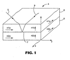
- Fig.1 is a schematic perspective view of a stack of two polymeric layers forming an interface
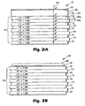
- Fig. 2A, Fig. 2B , Fig. 2C, Fig. 2D and Fig. 2E are schematic cross-sectional views of films of the invention.
- Fig. 3 is a schematic cross-sectional views of a film of the invention having an adhesive backing
- Fig. 4 and Fig. 5 are schematic cross-sectional views of pre-laminates of the invention.
- Fig. 6 is a schematic cross-sectional view of a windshield of the invention.
- Fig. 7 is a perspective view of the windshield of Fig. 6 ;
- Fig. 8 is a schematic view of an apparatus for carrying out a process of the invention.
- Fig. 9 is a schematic cross-sectional view of architectural glazing of the invention.
- Fig.10 is a graph showing transmittance and reflectance for a film having a birefringent dielectric multilayer support and a metal layer as described in Example 1;
- Fig.11 is a graph showing transmittance and reflectance for the birefringent dielectric multilayer support of Fig. 10 without the metal layer.
- crosslinked polymer we mean a polymer in which polymer chains are joined together by covalent chemical bonds, usually via crosslinking molecules or groups, to form a network polymer.
- a crosslinked polymer is generally characterized by-insolubility, but may be swellable in the presence of an appropriate solvent.
- polymer includes homopolymers and copolymers, as well as homopolymers or copolymers that may be formed in a miscible blend, e.g., by coextrusion or by reaction, including, e.g., transesterification.
- copolymer and copolyester include both random and block copolymers.
- an “extensible” metal or metal alloy layer we refer to a layer that when incorporated into a visible light-transmissive film can be stretched by at least 3% in an in-plane direction without loss of electrical continuity and without forming visible discontinuities in the surface of the metal or metal alloy layer as detected by the naked eye at a distance of about 0.25 meters.
- a visible light-transmissive support, layer, film or article we mean that the support, layer, film or article has a transmission in the visible portion of the spectrum, T vis , of at least about 20%, measured along the normal axis.
- T vis transmission in the visible portion of the spectrum
- an “infrared-reflective” support, layer, film or article we mean that the support, layer, film or article reflects at least about 50% of light in a band at least 100 nm wide in a wavelength region from about 700 nm to about 2000 nm, measured at a near-normal angle (e.g., at about a 6° angle of incidence).
- light we mean solar radiation.
- a reflection band we mean a range of wavelengths of light that is substantially reflected by the film or article in question.
- a reflection band of the film or other article is said to be “broadened” when the range of substantially reflected wavelengths of light for the entire film or article spans a larger range of wavelengths than the range of substantially reflected wavelengths of light associated with (1) the multilayer support by itself, and (2) the additional layer(s) by itself/themselves.
- non-planar surface or article e.g., of glass or other glazing material
- surface or article has a continuous, intermittent, unidirectional or compound curvature.
- compound curvature we mean that the surface or article curves in two different, non-collinear directions from a single point.
- FIG.1 two layers of an MOF support 4 are shown in perspective view. Typically, the support will have tens or hundreds or even thousands of such layers.
- Layer 6 has in-plane indices of refraction n1x and n1y in the x- and ⁇ -axis directions and index of refraction n1z in the z-axis direction.
- Layer 8 has in-plane indices of refraction n2x and n2y in the x- and ⁇ -axis directions and index of refraction n2z in the z-axis direction.
- Incident light ray 7 is refracted as it passes through layer 6, reflected at interface 7 , refracted as it passes once again through layer 6 and exits layer 6 as reflected ray 9 .
- the reflectance characteristics of the multilayer support are determined by the in-plane indices of refraction for the layers within the support. In particular, reflectivity depends upon the relationship between the indices of refraction of each layer material in the x, y, and z directions.
- the MOF support preferably is formed using at least one uniaxially birefringent material, in which two indices (typically along the x and y axes, or nx and ny) are approximately equal, and different from the third index (typically along the z axis, or nz).
- a film 10 is set forth in cross-sectional schematic view.
- Layers 12 have been stretched and have a higher index of refraction n1 than index n2 of adjacent layers 14 .
- the stack of layers 12, 14 forms MOF support 15 .
- Crosslinked polymeric layer 16 lies atop support 15 .
- Metal or metal alloy layer 18 (which as noted above can be referred to simply as a "metal layer”) lies atop layer 16 .
- Incident light rays such as ray 20 are partially reflected at the first surface of metal layer 18 , the interface 22 between layers 18 and 16 , the interface 24 between layer 16 and the adjacent layer 12 , and at interfaces such as 26a , 26b and the like between adjacent layers 12,14.
- Layer 18 is sufficiently thin so that layer 18 and film 10 as a whole are visible light-transmissive. Layer 18 is sufficiently thick so that the reflection band of film 10 as a whole is broadened. Thus in such a film, metal layer 18 combines with the MOF support 15 to provide a film having a broadened reflection band (e.g., for infrared radiation) compared to a film containing only the metal layer or only the MOF support.
- Crosslinked polymeric layer 16 is in intimate contact with metal layer 18 and is believed to discourage cracking, wrinkling or separation of metal layer 18 when film 10 is stretched or otherwise subjected to strain. Use of a crosslinked polymeric layer in film 10 makes film 10 more readily orientable without damaging nearby metal layer(s) or altering the spacing of a stack of such metal layers.
- FIG. 2B another film 28 is shown in cross-sectional schematic view.
- Film 28 resembles film 10 but metal layer 18 lies between support 15 and crosslinked polymeric layer 29.
- Layer 18 is sufficiently thin so that layer 18 and film 28 as a whole are visible light-transmissive.
- Layer 18 is sufficiently thick: so that the reflection band of film 28 as a whole is broadened.
- Crosslinked polymeric layer 29 is in intimate contact with metal layer 18, and is believed to discourage cracking, wrinkling or separation of metal layer 18 when film 28 is stretched or otherwise subjected to strain.
- Layer 29 also functions as a protective layer over metal layer 18.
- a third film 30 is shown in cross-sectional schematic view.
- Film 30 resembles films 10 and 28 but metal layer 18 has a crosslinked polymeric layer 32, 34 adjacent to each of its faces.
- Crosslinked polymeric layers 32, 34 both are in intimate contact with metal layer 18, and are especially effective at discouraging cracking, wrinkling or separation of metal layer 18 when film 30 is stretched or otherwise subjected to strain.
- a fourth film 40 is shown in cross-sectional schematic view.
- crosslinked polymeric layer 42 lies atop metal layer 18 and serves as a spacing layer between metal layer 18 and second metal layer 44.
- Crosslinked polymeric protective layer 46 lies atop second metal layer 44.
- layers 18, 42, 44 form a Fabry-Perot interference filter stack 48.
- the metal layers 18, 44 in stack 48 are sufficiently thin so that layers 18, 44 and film 40 as a whole are visible Light-transmissive.
- Layers 18, 44 and crosslinked polymeric spacing layer 42 are sufficiently thick so that the reflection band of film 40 as a whole is broadened.
- a fifth film 50 is shown in cross-sectional schematic view.
- Film 50 resembles film 30 but a second crosslinked polymeric layer 52 lies atop second metal layer 44 and serves as a spacing layer between second metal layer 44 and third metal layer 54.
- Crosslinked polymeric protective layer 56 lies atop third metal layer 54.
- Layers 18, 44, 54 are sufficiently thin so that layers 18, 44, 54 and film 50 as a whole are visible light-transmissive.
- Layers 18, 44, 54 and crosslinked polymeric spacing layers 42, 52 are sufficiently thick so that the reflection band of film, 50 as a whole is broadened.
- FIG. 3 an adhesive-backed film 60 is shown in cross-sectional schematic view.
- Film 60 is like film 40 of Fig. 2D but has a layer of adhesive 62 on the lowermost surface of support 15 .
- the adhesive permits the mounting of film 60 on a variety of surfaces, including non-planar surfaces and surfaces having a compound curvature.
- Fig. 4 shows a pre-laminate 140.
- Pre-laminate 140 includes a mechanical energy-absorbing layer 134 made of PVB joined to protective layer 122 of film 130.
- Film 130 includes MOF support 112 made of alternating layers (not depicted in Fig. 4 ) of two polyesters.
- Fabry-Perot interference stack 114 lies atop support 112.
- S tack 114 includes a first thin layer 116 made of silver, a crosslinked polymeric spacing layer 118 made of a crosslinked acrylate polymer, and a second thin metal layer 120 made of silver.
- Crosslinked polymeric base coat layer 132 lies between stack 114 and support 112.
- Optional protective layer 122 made of crosslinked acrylate polymer lies atop stack 114.
- Fig. 5 shows another pre-laminate 150.
- Pre-laminate 150 includes a second mechanical energy-absorbing layer 134 joined to MOF support 112 of film 140. This provides a more durable pre-laminate than the pre-laminate shown in Fig. 4 .
- Fig. 6 shows a cross-sectional view of a laminated safety windshield 160.
- Windshield 160 has a continuously curved surface whose radius of curvature is relatively large near the center region (shown only as broken lines in Fig. 6 ) of windshield 160 but decreases to a relatively small value near the more sharply curved end regions 161, all as described in copending U.S. application Serial Number 10/222,466 , entitled "POLYMER-METAL INFRARED INTERFERENCE FILTER".
- nip rollers 166, 168 are being used to de-air and tack pre-laminate 150 between the two pieces of glass 32a and 32b.
- Fig. 7 shows a perspective view of windshield 160 of Fig 6 .
- Curved regions 161, 162,163 and 164 have compound curvatures. If pre-laminate 150 shrinks somewhat during the de-airing/lamination and autoclave steps that are used to form windshield 160 , then it will be easier to obtain a wrinkle-free appearance through windshield 160 .
- the disclosed films include a multilayer optical film support.
- a variety of MOF supports can be employed.
- a preferred method for preparing a suitable MOF support involves biaxially orienting (stretching along two axes) a suitable multilayer polymeric film. If the adjoining layers have different stress-induced birefringence, biaxial orientation of the multilayer optical film results in differences between refractive indices of adjoining layers for planes parallel to both axes, resulting in the reflection of light of both planes of polarization.
- a uniaxially birefringent material can have either positive or negative uniaxial birefringence.
- Positive uniaxial birefringence occurs when the index of refraction in the z direction (nz) is greater than the in-plane indices (nx and ny).
- Negative uniaxial birefringence occurs when the index of refraction in the z direction (nz) is less than the in-plane indices (nx and ny).
- Multilayer optical films that are oriented in two mutually perpendicular in-plane axes are capable of reflecting an extraordinarily high percentage of incident light depending on factors such as the number of layers, the f-ratio (the ratio of the optical thicknesses in a two component multilayer optical film, see U.S. Patent No. 6,049,419 ) and the indices of refraction, and are highly efficient mirrors.
- the thicknesses of the layers in the MOF support also affect the reflectance characteristics of the multilayer optical film. All physical thicknesses of MOF layers discussed herein are measured after any orientation or other processing. Adjacent pairs of layers (one having a high index of refraction, and the other a low index) preferably have a total optical thickness that is 1/2 of the wavelength of the light to be reflected. To achieve maximum reflectivity in a two-component system, the individual layers of the MOF support preferably have an optical thickness that is 1/4 of the wavelength of the light to be reflected, although other ratios of optical thicknesses within the layer pairs may be chosen for other reasons.
- an infrared MOF support can be made transparent in the visible region of the spectrum, even at high angles of incidence.
- Preferred MOF supports are highly reflective for both s and p polarized light for any incident direction, and have an average reflectivity of at least 50%, preferably 70%, and more preferably 90%, over at least a 100 nm wide band in a wavelength region of interest.
- the wavelength region of interest may vary widely depending on the intended application.
- the wavelength region of interest is within the infrared region (about 700 nm to about 2000 nm), and the film is engineered to reflect incident radiation over at least a 100 nm wide band in that region.
- IR reflecting MOF support will also have a visible light transmission of at least about 70% at 550 nm.
- the MOF support is a two component narrow-band multilayer optical film designed to eliminate visible color due to higher order reflections that occur in the visible region of the spectrum from first order reflecting bands that occur in the IR region above about 1200 nm.
- the bandwidth of light to be blocked, i.e., not transmitted, by this MOF support at a zero degree observation angle is from approximately 700 to 1200 nm.
- the short wavelength bandedge is typically shifted by about 100 to 150 nm away from the long wavelength visible bandedge into the IR so that the reflecting band does not shift into the visible region of the spectrum at maximum use angles.
- the layer pairs of such an MOF support preferably have optical thicknesses ranging from 425 to 600 nm (1/2 the wavelength of the light desired to be reflected) to reflect the near infrared light. More preferably, for a quarter wave stack, such an IR reflecting MOF support has individual layers each having an optical thickness ranging from 212 to 300 nm (1/4 the wavelength of the light desired to be reflected), to reflect near infrared light.
- the layer pairs in the MOF support have varying relative thicknesses, referred to herein as a layer thickness gradient, which are selected to achieve the desired bandwidth of reflection over a widened reflection band.
- the layer thickness gradient may be linear, with the thickness of the layer pairs increasing at a constant rate across the thickness of the MOF support, so that each layer pair is a certain percent thicker than the thickness of the previous layer pair.
- the layer thicknesses may also decrease, then increase, then decrease again from one major surface of the MOF support to the other, or may have an alternate layer thickness distribution designed to increase the sharpness of one or both bandedges, e.g., as described in U.S. Patent No. 6,157,490 .
- the MOF support can include an extended bandedge two component IR reflecting film construction having a six layer alternating repeating unit as described in U.S. Patent No. 5,360,659 .
- This construction suppresses the unwanted second, third, and fourth order reflections in the visible wavelength region of between about 380 to about 700 nm, while reflecting light in the infrared wavelength region of between about 700 to about 2000 nm. Reflections higher than fourth order will generally be in the ultraviolet, not visible, region of the spectrum or will be of such a low intensity as to be unobjectionable.
- Such an MOF support has alternating layers of first (A) and second (B) polymeric materials in which the six layer alternating repeat unit has relative optical thicknesses of about .778A.111B.111A.778B.111A.111B.
- the use of only six layers in the repeat unit results in more efficient use of material and is relatively easy to manufacture.
- the two component MOF support can employ a first portion of alternating layers having the above-described six layer alternating repeating unit that reflects infrared light of wave lengths between about 1200 - 2000 nm, and a second portion of alternating layers having an AB repeat unit and substantially equal optical thicknesses that reflects infrared light of wavelengths between about 700 - 1200 nm.
- a hybrid design results in broadened reflection of light across the infrared wavelength region.
- This hybrid design may be provided as described, for example, in U.S. Patent No. 5,360,659 , but has broader application in that it is useful with any of the films described herein.
- the layer thicknesses of both portions of alternating layers can be adjuster to place the reflecting band within the infrared spectrum so as to minimize any perceived color change with angle.
- the MOF support can include more than two optically distinguishable polymers.
- a third or subsequent polymer can for example be employed as an adhesion-promoting layer between a first polymer and a second polymer within an MOF support, as an additional component of a stack for optical purposes, as a protective boundary layer between optimal stacks, as a skin layer, as a functional coating, or for any other purpose.
- the composition of a third or subsequent polymer, if any, is not limited.
- Examples of IR reflecting MOF supports that contain more than two distinguishable polymers include those described in U.S. Reissue No. Re 34,605 .
- Re 34,605 describes a film including three diverse substantially transparent polymeric materials, A, B, and C and having a repeating unit of ABCB.
- the layers have an optical thickness of between about 90 nm to about 450 nm, and each of the polymeric materials has a different index of refraction, n i .
- a layer thickness gradient can also be introduced across the thickness of such an MOF support, with the layer thicknesses preferably increasing monotonically across the thickness of the MOF support.
- the first polymeric material (A) differs in refractive index from the second polymeric material (B) by at least about 0.03
- the second polymeric material (B) differs in refractive index from the third polymeric material (C) by at least about 0.03
- the refractive index of the second polymeric material (B) is intermediate the respective refractive indices of the first (A) and third (C) polymeric materials.
- Any or all of the polymeric materials may be synthesized to have the desired index of refraction by utilizing a copolymer or miscible blend of polymers.
- MOF support embodiment is described in U.S. Patent No. 6,207,260 .
- the optical films and other optical bodies of that patent exhibit a first order reflection band for at least one polarization of electromagnetic radiation in a first region of the spectrum while suppressing at least the second, and preferably also at least the third, higher order harmonics of the first reflection band.
- the percent reflection of the first order harmonic remains essentially constant, or increases, as a function of angle of incidence.
- At least one of the differences n z A - n z B and n z B - n z C is less than or equal to about -0.05.
- any of the above described MOF supports can be combined with a "gap-filler" component that increases the optical efficiency of the MOF support when the reflecting band is selectively positioned away from the visible region of the spectrum to minimize perceived color change with angle.
- a "gap-filler" component works at normal angles to absorb or reflect IR radiation in the region between the edge of the visible spectrum and the short wavelength bandedge of the IR reflecting band.
- the materials selected for the layers in the stack also determine the reflectance characteristics of the MOF support. Many different materials may be used, and the exact choice of materials for a given application depends on the desired match and mismatch obtainable in the refractive indices between the various optical layers along a p articular axis, as well as on the desired physical properties of the finished film. For simplicity, the discussion that follows will concentrate on MOF supports containing layer pair-s made from only two materials, referred to herein as the first polymer and the second polymer. For discussion purposes the first polymer will be assumed to have a stress optical coefficient with a large absolute value. Thus the first polymer will be capable of developing a large birefringence when stretched.
- the birefringence may be developed between two orthogonal directions in the plane of the MOF support, between one or more in-plane directions and the direction perpendicular to the MOF support film plane, or a combination of these.
- the first polymer should maintain birefringence after stretching, so that the desired optical properties are imparted to the finished MOF support.
- the refractive index criteria apply equally to any direction in the film plane. It is typical for the indices of any given layer to be equal or nearly so in orthogonal in-plane directions. Preferably, however, the in-plane indices of the first polymer differ as much as possible from the in-plane indices of the second polymer. If before orientation the first polymer has an index of refraction higher than that of the second polymer, the in-plane indices of refraction of the first polymer preferably increase in the direction of stretch, and the z-axis index preferably decreases to match that of the second polymer.
- the in-pl ane indices of refraction of the first polymer preferably decrease in the direction of stretch, and the z-axis index preferably increases to match that of the second polymer.
- the second polymer preferably develops little or no birefringence when stretched, or develops birefringence of the opposite sense (positive - negative or negative - positive), such that its in-plane refractive indices differ as much as possible from those of the first polymer in the finished MOF support.
- neither the first nor the second MOF support polymer has appreciable absorbance bands within the bandwidth of interest. Thus, all incident light within the bandwidth will be either reflected or transmitted. However, for some applications, it may be useful for one or both of the first and second polymers to absorb specific wavelengths, either totally or in part.
- the MOF support can also contain optional non-optical layers as described in more detail below.
- the optical layers of the MOF support e.g., the first and second polymer layers
- the optional non-optical layers of the MOF support are composed of polymers.
- the polymers can be formed using comonomers.
- the use of such comonomers should not substantially impair the stress optical coefficients of the MOF support layers or the retention of birefringence after stretching. In practice, this will impose a practical upper limit on the comonomer content, the exact value of which will vary with the choice of comonomer(s) employed. Some compromise in optical properties may be accepted, however, if comonomer incorporation results in improvement of other properties.
- Polyesters are preferred first polymers for use in making the MOF support, and generally include carboxylate and glycol subunits generated by reactions of carboxylate monomers with glycol monomers.
- Each carboxylate monomer has two or more carboxylic acid or ester functional groups and each glycol monomer has two or more hydroxy functional groups.
- the carboxylate monomers may all be the same or there may be two or more different types of molecules. The same applies to the glycol monomers.
- Also included within the term "polyester” are polycarbonates derived from the reaction of glycol monomers with esters of carbonic acid.
- Preferred carboxylate monomers for use in forming the carboxylate subunits of polyester layers in an MOF support include, for example, 2,6-naphthalene dicarboxylic acid and isomers thereof; terephthalic acid; isophthalic acid; phthalic acid; azelaic acid; adipic acid; sebacic acid; norbornene dicarboxylic acid; bi-cyclooctane dicarboxylic acid; 1,6-cyclohexane dicarboxylic acid and isomers thereof; t-butyl isophthalic, acid, trimellitic acid, sodium sulfonated isophthalic acid; 2,2'-biphenyl dicarboxylic acid and isomers thereof; and lower alkyl esters of these acids, such as methyl or ethyl esters.
- lower alkyl refers, in this context, to C 1 -C 10 straight-chained or branched alkyl groups.
- Preferred glycol monomers for use in forming glycol subunits of the polyester layers include ethylene glycol; propylene glycol; 1,4-butanediol and isomers thereof; 1,6-hexanediol; neopentyl glycol; polyethylene glycol; diethylene glycol; tricyclodecanediol; 1,4-cyclohexanedimethanol and isomers thereof; norbornanediol; bicyclo-octanediol; trimethylol propane; pentaerythritol; 1,4-benzenedimethanol and isomers thereof; bisphenol A; 1,8-dihydroxy biphenyl and isomers thereof; and 1,3-bis(2-hydroxyethoxy)benzene.
- PEN Polyethylene naphthalate
- PEN is a particularly useful polyester for use in making the MOF support, and often is selected as the first polymer.
- PEN can be made, for example, by reaction of a naphthalene dicarboxylic acid with ethylene glycol.
- Polyethylene 2,6-naphthalate is a particularly preferred PEN.
- PEN has a large positive stress optical coefficient, retains birefringence effectively after stretching, and has little or no absorbance within the visible range.
- PEN also has a large index of refraction in the isotropic state. Its refractive index for polarized incident light of 550 nm wavelength increases when the plane of polarization is parallel to the stretch direction from about 1.64 to as high as about 1.9.
- PEN polyethylene terephthalate
- first polymers include, for example, polybutylene 2,6-naphthalate ("PBN”), polyethylene terephthalate (“PET”), and copolymers thereof.
- PBN polybutylene 2,6-naphthalate
- PET polyethylene terephthalate
- Non-polyester polymers are also useful in creating MOF supports.
- polyether imides can be used with polyesters such as PEN or a PEN copolymer (“coPEN”), to generate a multilayer reflective mirror.
- polyester/non-polyester combinations such as PET and polyethylene (e.g., the poly (ethylene-co-octene) or "PE-PO" available from Dow-Dupont Elastomers under the trade designation ENGAGETM 8200); can also be used.
- suitable first polymers are described, for example, in U.S. Patent No. 6,268,961 , in PCT Published Application Nos. WO 99/36248 and WO 99/36262 , and in U.S. Patent No. 6,498,683 .
- Another preferred first polymer is a coPEN with carboxylate subunits derived from 90 mol% dimethyl naphthalene dicarboxylate and 10 mol% dimethyl terephthalate and glycol subunits derived from.
- Another preferred first polymer is a PET having an IV of 0.74 dL/g, available from Eastman Chemical Company.
- the second polymer in the MOF support preferably is chosen : so that the refractive index of the second polymer differs significantly, in at least one direction in the finished MOF support, from the index of refraction of the first polymer in the same direction. Because polymeric materials are typically dispersive, that is, their refractive indices vary with wavelength, these conditions must be considered in terms of a particular spectral bandwidth of interest. It will be understood from the foregoing discussion that the choice of a second polymer is dependent not only on the intended application of the film of the invention, but also on the choice made for the first polymer and upon the MOF support and film processing conditions.
- the second optical layers can be made from a variety of second polymers having a glass transition temperature compatible with that of the first polymer and having a refractive index similar to the isotropic refractive index of the first polymer.
- suitable second polymers include vinyl polymers and copolymers made from monomers such as vinyl naphthalenes, styrene, maleic anhydride, acrylates, and methacrylates. Further examples of such polymers include polyacrylates, polymethacrylates such as poly (methyl methacrylate) ("PMMA”), and isotactic or syndiotactic polystyrene.
- Other suitable second polymers include condensation polymers such as polysulfones, polyamides, polyurethanes, polyamic acids, and polyimides.
- the second optical layers in the MOF support can also be formed from polymers such as polyesters and polycarbonates.
- Preferred MOF support second polymers include homopolymers of PMMA such as those available from Ineos Acrylics, Inc. under the trade designations CP71 and CP80, and polyethyl methacrylate ("PEMA”) which has a lower glass transition temperature than PMMA.
- PMMA polymethyl methacrylate
- Additional preferred second polymers include copolymers of PMMA ("coPMMA”), e.g., a coPMMA made from 75 wt% methylmethacrylate (“MMA”) monomers and 25 wt% ethyl acrylate (“EA”) monomers such as that available from Ineos Acrylics, Inc., under the trade designation PERSPEXTM CP63; a coPMMA formed with MMA comonomer units and n-butyl methacrylate (“nBMA”) comonomer units; and a blend of PMMA and poly(vinylidene fluoride) (“PVDF”) such as that available from Solvay Polymers, Inc.
- coPMMA e.g., a coPMMA made from 75 wt% methylmethacrylate (“MMA”) monomers and 25 wt% ethyl acrylate (“EA”) monomers such as that available from Ineos Acrylics, Inc., under the trade designation PERSPEXTM CP63
- Second optical layers can also be made from a functionalized polyolefin, e.g., a linear low density polyethylene-g-maleic anhydride (“LLDPE-g-MA”) such as that available from E.I.
- LLDPE-g-MA linear low density polyethylene-g-maleic anhydride
- BYNELTM 4105 from a copolyester ether elastomer
- ECDELTM syndiotactic polystyrene
- coPET copolymer or blend based upon terephthalic acid
- PET copolymer of PET employing a second glycol, e.g.,
- first/second polymers for optical layers in IR reflective MOF support films include PEN/PMMA, PET/PMMA or PET/coPMMA, PEN/COPE, PET/COPE, PEN/sPS, PET/sPS, PEN/coPET, PEN/PETG, and PEN/THV.
- PEN/PMMA PET/PMMA or PET/coPMMA
- PEN/COPE PET/COPE
- PEN/sPS PET/sPS
- PEN/coPET PEN/PETG
- PEN/THV PEN/THV.
- the MOF support optionally includes one or more non-optical layers, e.g., one or more non-optical skin layers or one or more non-optical interior layers such as a protective boundary layer ("PBL") between packets of optical layers.
- Non-optical layers can be used to give further strength or rigidity to the MOF support or to protect it from harm or damage during or after processing.
- Materials may also be chosen for the non-optical layers to import or improve various properties, e.g., , tear resistance, puncture resistance, toughness, weatherability, and solvent resistance of the MOF support or of the films of the invention.
- one or more of the non-optical layers are placed so that at least a portion of the light to be transmitted, polarized, or reflected by MOF support or the films of the invention also travels through these layers (in other words these non-optical layers can be placed in the path of light that travels through or is reflected by the MOF support or the films of the invention).
- the non-optical layers preferably do not substantially affect the reflective properties of the MOF support or the films of the invention over the wavelength region of interest. Properties of the non-optical layers such as crystallinity and shrinkage characteristics may need to be considered along with the properties of the MOF support optical layers in order to provide a film that does not crack or wrinkle when laminated to severely curved substrates.
- the non-optical layers in such an MOF support can be selected from many appropriate materials. Factors to be considered in selecting a material for a non-optical layer include percent elongation to break, Young's modulus, tear strength; adhesion to interior layers, percent transmittance and absorbance in an electromagnetic bandwidth of interest, optical clarity or haze, refractive indices as a function of frequency, texture, roughness, melt thermal stability, molecular weight distribution, melt rheology, coextrudability, miscibility and rate of inter-diffusion between materials in the optical and non-optical layers, viscoelastic response, relaxation and crystallization behavior under draw conditions, thermal stability at use temperatures, weatherability, ability to adhere to coatings and permeability to various gases and solvents.
- the non-optical layers may be formed from a variety of polymers, such as polyesters, including any of the polymers used in the first and second optical layers of the MOF support.
- the material selected for a non-optical layer will be similar to or the same as the material selected for the second optical layers.
- use of coPEN, coPET, or other copolymer material for a skin layer can reduce the "splittiness" (the breaking apart of an MOF support due to strain-induced crystallinity and alignment of a majority of the polymer molecules in the direction of orientation) of the MOF support.
- Non-optical layers containing coPEN typically will orient very little when stretched under the conditions used to orient the first optical layers, and thus have little strain-induced crystallinity.
- the polymers of the first optical layers, the second optical layers and the optional non-optical layers in the MOF supports are chosen to have similar rheological properties (e-g., melt viscosities) so that they can be co-extruded without flow disturbances.
- the second optical layers, skin layers and optional other non-optical layers in the MOF support have a glass transition temperature (“Tg") that is either below or no greater than about 40°C above the glass transition temperature of the first optical layers. More preferably the Tg of the second optical layers, skin layers, and optional non-optical layers is below the Tg of the first optical layers.
- LO length orientation
- preferred skin layer materials include PMMA and polycarbonate because of the durability of these materials and their ability to protect the MOF support from UV radiation.
- a skin layer can also be coextruded on one or both major surfaces of the MOF support during its manufacture to protect the MOF support optical layers from the high shear conditions along the feedblock and die walls.
- a skin layer having desirable chemical or physical properties can be obtained by mixing one or more suitable additives, e.g., a UV stabilizer, into the polymer melt that makes up the skin layer and coextruding the resulting skin layer onto one or both sides of the MOF support layers during manufacture-
- additional layers can be coextruded on the outside of the skin layers during manufacture of the MOF support; they may be coated onto the MOF support in a separate coating operation; or they may be laminated to the MOF support as a separate film, foil, or rigid or semi-rigid reinforcing substrate.
- the skin layers and other optional non-optical layers in the MOF support can be thicker than, thinner than, or the same thickness as the optical layers of the MOF support.
- the thickness of the skin layers and optional non-optical layers is generally at least four times, typically at least 10 times, and can be at least 100 times the thickness of at least one of the individual optical layers of the MOF support.
- the thickness of the non-optical layers can be varied to make an MOF support having a particular thickness.
- the overall physical thickness of the MOF support will depend on the desired application. Preferably the MOF support is about 0.01 to about 1 mm thick.
- the films of the invention also include a metal or metal layer and a crosslinked polymeric layer atop the MOF support. These layers can be present in either order, viz., with the metal or metal alloy layer between the MOF support and the crosslinked polymeric layer, or with the crosslinked polymeric layer between the MOF support and the metal or metal alloy layer. Preferably, more than one metal or metal alloy layer is present in the disclosed film. As noted above, these metal or metal alloy layers can be referred to as metal layers for brevity. Most preferably, the disclosed films include at least two metal layers separated by a crosslinked polymeric spacing layer, with the metal layers and crosslinked polymeric spacing layer forming an infrared-rejecting Fabry-Perot optical interference stack. More than one such stack can be present in the film if desired. Additional stacks can conveniently be formed by placing additional crosslinked polymeric layers and metal layers atop the previous stack(s).
- the first, second and any additional metal layers in the film can be the same as or different from one another.
- Preferred metals include elemental silver, gold copper, nickel, chrome, and stainless steel, with silver being especially preferred. Alloys or dispersions containing these metals in admixture with one another or with other metals also can be employed.
- the metal layers need not have the same thickness.
- the metal layers are sufficiently thick so as to be continuous, and sufficiently thin so as to ensure that the film and articles containing the film will have the desired degree of visible light transmission.
- the physical thickness (as opposed to the optical thickness) of the metal layers is about 3 to about 50 nm, more preferably about 4 to about 15 nm.
- the first and any additional metal layers preferably are applied using techniques employed in the film metallizing art such as sputtering (e.g., cathode or planar magnetron sputtering), evaporation (e.g., resistive or electron beam evaporation), chemical vapor deposition, plating and the like.
- sputtering e.g., cathode or planar magnetron sputtering
- evaporation e.g., resistive or electron beam evaporation
- chemical vapor deposition e.g., plating and the like.
- the metal layers can be used for purposes such as antennae, electromagnetic shielding, and for thin film heating applications such as de-fogging, de-misting, defrosting or deicing.
- Thin film heating applications can require substantial current-carrying ability.
- two or more of the metallized film layers are electrically connected together in parallel using busbars, e.g., as shown in U.S. Patent Nos. 3,529,074 , 4,782,216 , 4,786,783 , 5,324,374 and 5,332,888 .
- the combination of multiple current-carrying metal layers separated by crosslinked polymeric spacing layers provides a stack having increased resistance to delamination or fracture when subjected to bending, flexing and stretching, as described in more detail in copending U.S. application Serial No. 10/222,449 , and entitled “FLEXIBLE ELECTRICALLY CONDUCTIVE INFRARED INTERFERENCE FILTER” and in copending U.S. application Serial Number 10/222,465 , entitled “DURABLE TRANSPARENT EMI SHIELDING FILM".
- Even very small scratches or fractures within the metal layer can cause early failure of current-carrying embodiments of the film. Such failures often are due to hot spot formation, especially when the scratch or fracture is perpendicular to the direction of current flow through the metal layer.
- the layers will maintain electrical conductivity after the application of more than 0.15 W/cm 2 power to the film.
- a preferred pretreatment regimen involves electrical discharge pretreatment of the support in the presence of a reactive or non-reactive atmosphere (e.g., plasma, glow discharge, corona discharge, dielectric barrier discharge or atmospheric pressure discharge); chemical pretreatment; flame pretreatment; or application of a nucleating layer such as the oxides and alloys described in U.S. Patent Nos. 3,601,471 and 3,682,528 . These pretreatments help ensure that the surface of the support will be receptive to the subsequently applied metal layer. Plasma pretreatment is particularly preferred.
- a further particularly preferred pretreatment regimen involves coating the support with an inorganic or organic base coat layer such as layer 132 of Fig.
- Organic base coat layers, and especially crosslinked polymeric base coat layers, are especially preferred. Accordingly, in a preferred embodiment, the crosslinked polymeric layer lies between the MOF support and the metal layer.
- the crosslinked polymeric layer can be applied to the MOF support (or to the first metal layer atop the support) in a variety of ways.
- the crosslinked polymeric layer is formed by flash evaporation and vapor deposition of a radiation-crosslinkable monomer (e.g., an acrylate monomer), followed by crosslinking in situ (using, for example, an electron beam apparatus, UV light source, electrical discharge apparatus or other suitable device), as described in U.S. Patent Nos.
- the crosslinked polymeric layer can also be applied using conventional pre-polymer coating methods such as roll coating (e.g., gravure roll coating) or spray coating (e.g., electrostatic spray coating), then crosslinked using, for example, UV radiation.
- roll coating e.g., gravure roll coating
- spray coating e.g., electrostatic spray coating
- the desired chemical composition and thickness of the crosslinked polymeric layer will depend in part on the nature of the MOF support.
- the crosslinked polymeric layer preferably is formed from an acrylate monomer and typically will have a thickness of any a few nm up to about 2 micrometers.
- the crosslinked polymeric layer can be formed from a variety of organic materials.
- the spacing layer is crosslinked in situ after it is applied.
- the crosslinked polymeric layer is formed by flash evaporation, vapor deposition and crosslinking of a monomer as described above.
- Volatilizable (meth)acrylate monomers are preferred for use in such a process, with volatilizable acrylate monomers being especially preferred.
- Preferred (meth)acrylates have a number average molecular weight in the range of about 150 to about 600, more preferably about 200 to about 400.
- Other preferred (meth)acrylates have a value of the ratio of the molecular weight to the number of acrylate functional groups per molecule in the range of about 150 to about 600 g/mole/(meth)acrylate group, more preferably about 200 to about 400 g/mole/(meth)acrylate group.
- Fluorinated (meth)acrylates can be used at higher molecular weight ranges or ratios, e.g., about 400 to about 3000 molecular weight or about 400 to about 3000 g/mole/(meth)acrylate group. Coating efficiency can be improved by cooling the support.
- Particularly preferred monomers include multifunctional (meth)acrylates, used alone or in combination with other multifunctional or monofunctional (meth)acrylates, such as hexanediol diacryl ate, ethoxyethyl acrylate, phenoxyethyl acrylate, cyanoethyl (mono)acrylate, isobornyl acrylate, isobornyl methacrylate, octadecyl acrylate, isodecyl acrylate, lauryl acrylate, beta-carboxyethyl acrylate, tetrahydrofurfuryl acrylate, dinitrile acrylate, pentafluorophenyl acrylate, nitrophenyl acrylate, 2-phenoxyethyl acrylate, 2-phenoxyethyl methacrylate, 2,2,2-trifluoromethyl (meth)acrylate, diethylene glycol diacrylate, triethylene glycol diacrylate, triethylene glycol dimethacryl
- the crosslinked polymeric layer typically will have a refractive index of about 1.3 to about 1.7, and preferably will have an optical thickness of about 75 to about 200 nm, more preferably about 100 to about 150 nm and a corresponding physical thickness of about 50 to about 130 nm, more preferably about 65 to about 100 nm.
- Optical modeling can be employed to design suitable layer thicknesses in the disclosed articles.
- two exemplary target structures have respective layer physical thicknesses from the base coat through the topcoat of 129/12/104/12/54 nm or 116/10/116/10/55 nm.
- a crosslinked polymeric spacing layer has several advantages over a non-crosslinked polymeric spacing layer.
- a crosslinked polymeric spacing layer will neither melt nor soften as appreciably with heating as a non-crosslinked polymeric spacing layer, and thus is less likely to flow, deform or thin significantly under the simultaneous influence of temperature and pressure, as during a forming or laminating process.
- a crosslinked polymeric spacing layer is highly solvent resistant, whereas a non-crosslinked polymeric spacing layer may be dissolved or appreciably softened by solvents such as those used to form the non-crosslinked polymeric spacing layer.
- Crosslinked polymeric spacing layers can have greater resistance to liquids that may be encountered by the films of the present invention, such as cleaning solutions for window applications and automotive fluids such as gasoline, oil, transmission fluid, etc., for automotive applications.
- a crosslinked polymeric spacing layer may also have desirable physical properties compared to a non-crosslinked polymeric spacing layer fabricated from a similar polymer, such as higher modulus and stiffness, better elastic recovery when strained or better resilience.
- the adhesion of the first metal layer to the crosslinked polymeric layer can be improved by placing the first metal layer between crosslinked polymeric layers.
- the adhesion can also be improved by including an adhesion-promoting or anticorrosion additive in the crosslinked polymeric layer. This can affect the surface energy or other relevant characteristics of the interface between the crosslinked polymeric layer and the first metal layer.
- Suitable adhesion-promoting or anticorrosion additives include mercaptans, acids (such as carboxylic acids or organic phosphoric acids), triazoles, dyes and wetting agents.
- Ethylene glycol bis-thioglycolate (described in U.S. Patent No. 4,645,714 ) is a particularly preferred additive.
- the additive preferably is present in amounts sufficient to obtain the desired degree of increased adhesion, without causing undue oxidation or other degradation of the first metal layer.
- additional crosslinked polymeric spacing layers and metal layers can be applied atop the first metal layer.
- stacks containing 3 metal layers or 4 metal layers provide desirable characteristics for some applications.
- Stacks containing 2 to 4 metal layers in which each of the metal layers has a crosslinked polymeric layer adjacent to each of its faces are especially preferred.
- the smoothness and continuity of the second metal layer and its adhesion to an underlying layer preferably are enhanced by appropriate pretreatment of the underlying layer prior to application of the second metal layer, or by inclusion of a suitable additive in the underlying layer.
- Preferred pretreatments include the support pretreatments described above, with plasma pretreatment of the spacing layer being particularly preferred.
- the uppermost metal layer preferably is overcoated with a suitable protective layer such as layer 122 above.
- a suitable protective layer such as layer 122 above.
- the protective layer can be applied using conventional coating methods such as roll coating (e.g., gravure roll coating) or spray coating (e.g., electrostatic spray coating), then crosslinked using, for example, UV radiation.
- the protective layer is formed by flash evaporation, vapor deposition and crosslinking of a monomer as described above.
- Volatilizable (meth)acrylate monomers are preferred for use in such a protective layer, with volatilizable acrylate monomers being especially preferred.
- the index of refraction of the protective layer or other surface layer can be selected to minimize reflection at the interface caused by any difference in refractive indices between the PVB and the film.
- the protective layer can also be post-treated to enhance adhesion of the projective layer to a mechanical energy-absorbing material such as PVB.
- Preferred post-treatments include the support pretreatments described above, with plasma post-treatment of both sides of the film being particularly preferred.
- Preferred additives for the protective layer include the crosslinked polymeric layer additives described above.
- FIG. 8 An apparatus 180 that can conveniently be used to manufacture the disclosed films is shown in Fig. 8 .
- Powered reels 181a and 181b move MOF support 182 back and forth through apparatus 180 .
- Temperature-controlled rotating drums 183a and 183b, and idlers 184a,184b,184c, 184d and 184e carry MOF support 182 past metal sputtering applicator 185, plasma pretreater 186, monomer evaporator 187 and E-beam crosslinking apparatus 188.
- Liquid monomer 189 is supplied to evaporator 187 from reservoir 190.
- Successive layers can be applied to MOF support 182 using multiple passes through apparatus 180.
- Apparatus 180 can be enclosed in a suitable chamber (not shown in Fig. 8 ) and maintained under vacuum or supplied with a suitable inert atmosphere in order to discourage oxygen, water vapor, dust and other atmospheric contaminants from interfering with the various pretreatment, monomer coatings, crosslinking and
- the disclosed pre-laminates are formed by joining a film of the invention to one or more mechanical energy-absorbing layers such as layers 134 .
- the mechanical energy-absorbing layers can be made from a variety of materials that will be familiar to those skilled in the art, including PVB, polyurethanes ("PURs"), polyvinyl chloride, polyvinyl acetal, polyethylene, ethylene vinyl acetates and SURLYNTM resins (E. I. duPont de Nemours & Co.). PVB is a preferred material for the mechanical energy-absorbing layer.
- the thickness of the mechanical energy-absorbing layer will depend upon the desired application, but typically will be about 0.3 to about 1 mm.
- Various functional layers or coatings can be added to the MOF support, films or pre-laminates of the present invention to alter or improve their physical or chemical properties, particularly at one of the surfaces of the MOF support, film or pre-laminate.
- Such layers or coatings can include, for example, low friction coatings or slip particles to make the MOF support, film or the pre-laminate easier to handle during the manufacturing process; particles to add diffusion properties to the MOF support, film or pre-laminate or to prevent wet-out or Newton's rings when the MOF support, film or pre-laminate is placed next to another film or surface; adhesives such as pressure sensitive adhesives or hot melt adhesives; primers to promote adhesion to adjacent layers; and low adhesion backsize materials for use when the MOF support, film or pre-laminate is to be used in adhesive roll form.
- the functional layers or coatings can also include shatter resistant, anti-intrusion, or puncture-tear resistant film and coatings, for example, the functional layers described in WO 01/96115 .
- Additional functional layers or co atings can include vibration-damping film layers such as those described in WO 98/26927 and U.S. Patent No. 5,773,102 , and barrier layers to provide protection or to alter the transmissive properties of the MOF support, film or pre-laminate towards liquids such as water or organic solvents or towards gases such as oxygen, water vapor or carbon dioxide.
- These functional components can be incorporated into one or more of the outermost layers of the MOF support, film or pre-laminate, or they can be applied as a separate film or coating.
- the appearance or performance of the MOF support, film or pre-laminate such as by laminating a dyed film layer to the MOF support, film or pre-laminate, applying a pigmented coating to the surface of the MOF support, film or pre-laminate, or including a dye or pigment in one or more of the materials used to make the MOF support, film or pre-laminate.
- the dye or pigment can absorb in one or more selected regions of the spectrum, including portions of the infrared, ultraviolet or visible spectrum.
- the dye or pigment can be used to complement the properties of the MOF support, film or pre-laminate, particularly where the MOF support, film or pre-laminate transmits some frequencies while reflecting others.
- a particularly useful pigmented layer that can be employed in the MOF supports, films or pre-laminates of the invention is described in WO 2001/58989 .
- This layer can be laminated, extrusion coated or coextruded as a skin layer on the MOF support, film or pre-laminate.
- the pigment loading level can be varied between about 0.01 and about 1.0% by weight to vary the visible light transmission as desired.
- the addition of a UV absorptive cover layer can also be desirable in order to protect any inner layers of the MOF support or film that may be unstable when exposed to UV radiation.
- Additional functional layers or coatings that can be added to the MOF suppor-t, film or pre-laminate include, for example, antistatic coatings or films; flame retardants; UV stabilizers; abrasion resistant or hardcoat materials; optical coating; anti-fogging materials; magnetic or magneto-optic coatings or films; liquid crystal panels; electrochromic or electroluminescent panels; photographic emulsions; prismatic films; and holographic films or images. Additional functional layers or coatings are described, for example, in WO 97/01440 , WO 99/36262 , and WO 99/36248 .
- the MOF support, film or pre-laminate can be treated with, for example, inks or other printed indicia such as those used to display product identification, orientation information, advertisements, warnings, decoration, or other information.
- inks or other printed indicia such as those used to display product identification, orientation information, advertisements, warnings, decoration, or other information.
- Various techniques can be used to print on the MOF support, film or pre-laminate, such as, for example, screen printing, inkjet printing, thermal transfer printing, letterpress printing, offset printing, flexographic printing, stipple printing, laser printing, and so forth, and various types of ink can be used, including one and two component inks, oxidatively drying and UV-drying inks, dissolved inks, dispersed inks, and 100% ink systems.
- the disclosed films and pre-laminates can be joined or laminated to a wide variety of substrates.
- Typical substrate materials include glazing materials such as glass (which may be insulated, tempered, laminated, annealed, or heat strengthened) and plastics (such as polycarbonates and polymethylmethacrylate).
- the disclosed films and pre-laminates are especially useful in connection with non-planar substrates, especially those having a compound curvature.
- the films or pre-laminates preferably are capable of conforming to such non-planar sub strates during a lamination and de-airing process without substantial cracking or creasing.
- the disclosed films can be oriented and optionally heat set under conditions sufficient to assist the film in conforming without substantial wrinkling to a non-planar sub strate. This is especially useful when a non-planar substrate to which a film is to be laminated has a known shape or curvature, and especially when the substrate has a known severe compound curvature.
- the film can be caused to shrink in a controlled fashion during lamination, especially during nip roll lamination.
- the shrinkage of the film can be tailored in each in-plane direction to match the specific curvature characteristics of the substrate in those directions.
- the in-plane film or MOF support direction having the greatest shrinkage preferably is aligned with the dimension of the substrate having the least curvature, that is, the greatest radius of curvature.
- other measurements such as the depth of a raised or depressed area measured from the geometric surface defmed by a major surface of the substrate) can also be used if desired.
- the film shrinkage preferably will be greater than about 0.4% in both in-plane directions, more preferably greater than about 0.7% in at least one in-plane direction, and most preferably gre ater than about 1% in at least one in-plane direction.
- the overall film shrinkage preferably is limited to reduce edge delamination or "pull-in.”
- the film shrinkage preferably is less than about 3% in each in-plane direction, and more preferably less than about 2.5% in each in-plane direction.
- Shrinkage behavior will primarily be governed by factors such as the film or support material employed, and the film or support stretch ratio(s), heatset temperature, residence time and toe-in (the decrease in rail spacing in a tenter heatset zone measured relative to a maximum rail setting). Coatings can also change the shrinkage properties of a film. For example, a primer coating may reduce the transverse direction (“TD") shrinkage by about 0.2 % to about 0.4% and increase the machine direction (“MD”) shrinkage by about 0.1 to about 0.3%. Orienting and heat setting equipment can vary widely, and ideal process settings typically are determined experimentally in each case. Further details regarding techniques for manufacturing MOF supports having targeted shrinkage properties are described in WO01/96104 .
- the disclosed films can initially be laminated to a mechanical energy-absorbing layer or layers to form a pre-laminate such as pre-laminate 140 or 150, and then later laminated to a vehicular glazing sheet or sheets.
- a sandwich containing the film, the mechanical energy-absorbing layer or layers and the glazing sheet or sheets can also be assembled in a single lamination step. In either case, air should be removed from between the various layers during each lamination step.
- some level of adhesion should be established between the mechanical energy-absorbing layer or layers, the film and the glazing sheet or sheets.
- the mechanical energy-absorbing layer or layers preferably should not become sufficiently soft to flow before the final lamination step takes place.
- the mechanical energy-absorbing layer or layers preferably should help to tack the edges of the pre-laminate in position so that the film can shrink and form itself to the shape of the completed laminate.
- the laminate preferably is cooled at a controlled rate after autoclaving to avoid possible wrinkling within the film or delamination at the edges of the film.
- De-airing can be accelerated using the vacuum de-airing or nip roll processes described above.
- Preferably de-airing and lamination are carried out using one or more nip rollers.
- a representative nip roll apparatus is shown in U.S. Patent No. 5,085,141 . Other such devices will be familiar to those skilled in the art.
- the laminate preferably is heated in an autoclave to a temperature sufficient to cause the mechanical energy-absorbing layer or layers and the film of the invention to conform to the contours of the glazing sheet or sheets and form a final laminated glazing article.
- Sufficient pressure should also be applied during lamination to obtain at least partial bonding of the various layers of the laminate.
- temperatures of about 138°C to about 150°C and pressures of about 0.5 to about 1.5 MPa are typical. The heat and pressure cause the mechanical energy-absorbing layer or layers to flow and spread to fill up voids, form a uniform sandwich construction, and firmly bond the laminate layers together, while removing residual air (or dissolving it in the PVB) in a minimal time frame.
- one typical autoclave cycle involves (a) increasing the temperature and pressure from ambient to about 93°C and about 0.55 MPa within about 15 minutes, (b) increasing temperature to about 143°C while holding the pressure at about 0.55 MPa within about 40 minutes, (c) increasing the pressure to about 1.38 MPa while holding the temperature at about 143°C within about 10 minutes, (d) holding at this maximum temperature and pressure for about 20 minutes, (e) decreasing the temperature and the pressure to about 38°C and about 1 MPa within about 15 minutes, and (f) decreasing the pressure to ambient within about 4 minutes.
- the entire autoclave cycle is typically about 60 minutes to about 120 minutes.
- the disclosed films can also be employed in architectural glazing, e.g., such as the glazing articles described in U. S. Patent No. 4,799,745 .
- the manner of making such glazing articles will be apparent to those skilled in the art.
- useful architectural glazing articles can be made by substituting an MOF support for the interface layer 20 and a crosslinked polymeric layer for the spacing layer 18 in U. S. Patent No. 4,799,745 .
- the finished glazing articles preferably are optically clear.
- Fig. 9 shows a film 191 containing MOF support 192 and Fabry-Perot stack 193 containing first and second metal layers 194 and 196 separated by spacing layer 195. Film 191 is joined to a glass sheet 198 using a layer 197 of pressure sensitive adhesive.
- the disclosed films can be manufactured much more rapidly than films made using a sputter-coated inorganic dielectric layer or a solvent-applied uncrosslinked polymeric dielectric layer.
- the dielectric layer deposition step is a rate-limiting factor, whereas the disclosed process enables much more rapid deposition of the dielectric layer.
- the disclosed process can be carried out in a single chamber without removal of the film between coating steps, whereas the reported solvent-applied uncrosslinked dielectric layers appear to have been formed outside the chamber in which deposition of the metal layers took place.
- the films were stretched using SINTECHTM 200/S TENSILE TESTER (Instron Corp.) in order to determine the percent strain at which the film would stop conducting electricity.
- a 25.4 mm wide by about 200 mm long strip was cut from the center of a film sample.
- the narrow ends of the strip were painted on both sides with No. 22-201 silver paint (Katy Company).
- copper was folded over the painted edges to form a durable electrode at each end of the strip.
- the prepared strips were clamped into the jaws of the tensile tester, and alligator clips were used to connect a power supply to the copper electrodes. While using a gauge length of 101.6 mm and a crosshead speed of 25.4 mm/min, a constant voltage of 4 volts was supplied to the strip and the current flow was measured and recorded vs. % strain.
- the films of the invention were evaluated for sheet resistance using a non-contact conductivity measuring device (Model 717B Benchtop Conductance Monitor, Delcom Instruments Inc.).
- the value Te is defined as the ratio, expressed in percent, of the solar energy transmitted by a specimen from 250 nm to 2500 nm divided by the total incident solar energy.
- the value Ae is defined as the ratio, expressed in percent, of the solar energy absorbed by a specimen from 250 nm to 2500 nm divided by the total incident solar energy.
- Solar properties are calculated using solar irradiance data from ASTM E891 using air mass 1.5.
- the plasma pretreatment utilized a chrome target and an unbalanced dc magnetron operated at 1000 watts power (402 volts and 2.5 amps) under a nitrogen atmosphere with a nitrogen gas flow of 102 sccm-
- the acrylate coating employed a 50:50 mixture of IRR214 acrylate (UCB Chemicals) and lauryl acrylate that had been degassed for 1 hour by placing a container of the liquid monomer mixture into a bell jar and reducing pressure to approximately 1 millitorr.
- the degassed monomer was pumped at a flow rate of 2.45 ml/min through an ultrasonic atomizer into a vaporization chamber maintained at 276°C.
- Using a drum temperature of -21°C the monomer vapor was condensed onto the moving web and electron beam crosslinked using a single filament gun operated at 8.0 kV and 6.5 milliamps.
- Optical properties of the resulting infrared-rejecting film and for the uncoated support are shown in Fig. 10 and Fig. 11 , respectively.
- Curves T and R in each of Fig. 10 and Fig. 11 show transmission and reflection respectively.
- the reflection curves between about 700 and about 1100 nm the resulting infrared-rejecting film exhibited a significantly broadened reflection band.
- Table 1 show the formation of coated films having a T vis as high as about 73% and sheet resistance as low as 3.9 Ohms/square.
- Two samples of the film of Example 3 were also evaluated using the conductivity vs. strain test. Both film samples conducted current at up to 50% or more strain.
- Example 2 and Example 3 were subjected to optional plasma post-treatments on one or both sides of the film, and then laminated between glass sheets by placing a 304 mm by 304 mm sample of the film into the center of a sandwich made from two 0.05mm thick sheets of PVB placed between two 2mm glass sheets.
- the resulting laminate assemblies were de-aired using vacuum, then autoclaved to form an optically clear glazing article.
- the glazing articles were evaluated to determine their compressive shear strength.
- Table 2 Film Example number, presence or absence of plasma post-treatment atop the uppermost layer of the stack or on the underside of the support, and the measured compressive shear strength.
Landscapes
- Physics & Mathematics (AREA)
- General Physics & Mathematics (AREA)
- Optics & Photonics (AREA)
- Laminated Bodies (AREA)
- Optical Filters (AREA)
- Optical Elements Other Than Lenses (AREA)
- Mirrors, Picture Frames, Photograph Stands, And Related Fastening Devices (AREA)
Priority Applications (1)
| Application Number | Priority Date | Filing Date | Title |
|---|---|---|---|
| EP10181180A EP2280297A1 (en) | 2002-08-17 | 2003-08-15 | Enhanced heat mirror films |
Applications Claiming Priority (3)
| Application Number | Priority Date | Filing Date | Title |
|---|---|---|---|
| US10/222,473 US7215473B2 (en) | 2002-08-17 | 2002-08-17 | Enhanced heat mirror films |
| US222473 | 2002-08-17 | ||
| PCT/US2003/025652 WO2004017108A2 (en) | 2002-08-17 | 2003-08-15 | Enhanced heat mirror films |
Related Child Applications (1)
| Application Number | Title | Priority Date | Filing Date |
|---|---|---|---|
| EP10181180.0 Division-Into | 2010-09-28 |
Publications (2)
| Publication Number | Publication Date |
|---|---|
| EP1530733A2 EP1530733A2 (en) | 2005-05-18 |
| EP1530733B1 true EP1530733B1 (en) | 2011-09-28 |
Family
ID=31714972
Family Applications (2)
| Application Number | Title | Priority Date | Filing Date |
|---|---|---|---|
| EP03788554A Expired - Lifetime EP1530733B1 (en) | 2002-08-17 | 2003-08-15 | Enhanced heat mirror films |
| EP10181180A Withdrawn EP2280297A1 (en) | 2002-08-17 | 2003-08-15 | Enhanced heat mirror films |
Family Applications After (1)
| Application Number | Title | Priority Date | Filing Date |
|---|---|---|---|
| EP10181180A Withdrawn EP2280297A1 (en) | 2002-08-17 | 2003-08-15 | Enhanced heat mirror films |
Country Status (11)
| Country | Link |
|---|---|
| US (1) | US7215473B2 (enExample) |
| EP (2) | EP1530733B1 (enExample) |
| JP (3) | JP2005535938A (enExample) |
| KR (1) | KR20050051642A (enExample) |
| CN (1) | CN100392439C (enExample) |
| AT (1) | ATE526599T1 (enExample) |
| AU (1) | AU2003256431A1 (enExample) |
| BR (1) | BR0313519A (enExample) |
| MX (1) | MXPA05001757A (enExample) |
| TW (1) | TWI278651B (enExample) |
| WO (1) | WO2004017108A2 (enExample) |
Families Citing this family (182)
| Publication number | Priority date | Publication date | Assignee | Title |
|---|---|---|---|---|
| US5910854A (en) | 1993-02-26 | 1999-06-08 | Donnelly Corporation | Electrochromic polymeric solid films, manufacturing electrochromic devices using such solid films, and processes for making such solid films and devices |
| US5668663A (en) | 1994-05-05 | 1997-09-16 | Donnelly Corporation | Electrochromic mirrors and devices |
| US6891563B2 (en) | 1996-05-22 | 2005-05-10 | Donnelly Corporation | Vehicular vision system |
| US8294975B2 (en) | 1997-08-25 | 2012-10-23 | Donnelly Corporation | Automotive rearview mirror assembly |
| US6172613B1 (en) | 1998-02-18 | 2001-01-09 | Donnelly Corporation | Rearview mirror assembly incorporating vehicle information display |
| US6124886A (en) | 1997-08-25 | 2000-09-26 | Donnelly Corporation | Modular rearview mirror assembly |
| US6326613B1 (en) | 1998-01-07 | 2001-12-04 | Donnelly Corporation | Vehicle interior mirror assembly adapted for containing a rain sensor |
| US6445287B1 (en) | 2000-02-28 | 2002-09-03 | Donnelly Corporation | Tire inflation assistance monitoring system |
| US8288711B2 (en) | 1998-01-07 | 2012-10-16 | Donnelly Corporation | Interior rearview mirror system with forwardly-viewing camera and a control |
| US6693517B2 (en) | 2000-04-21 | 2004-02-17 | Donnelly Corporation | Vehicle mirror assembly communicating wirelessly with vehicle accessories and occupants |
| US6329925B1 (en) | 1999-11-24 | 2001-12-11 | Donnelly Corporation | Rearview mirror assembly with added feature modular display |
| US6477464B2 (en) | 2000-03-09 | 2002-11-05 | Donnelly Corporation | Complete mirror-based global-positioning system (GPS) navigation solution |
| WO2000026973A1 (en) * | 1998-11-02 | 2000-05-11 | Presstek, Inc. | Transparent conductive oxides for plastic flat panel displays |
| US7370983B2 (en) | 2000-03-02 | 2008-05-13 | Donnelly Corporation | Interior mirror assembly with display |
| WO2007053710A2 (en) | 2005-11-01 | 2007-05-10 | Donnelly Corporation | Interior rearview mirror with display |
| US7004593B2 (en) | 2002-06-06 | 2006-02-28 | Donnelly Corporation | Interior rearview mirror system with compass |
| EP1263626A2 (en) | 2000-03-02 | 2002-12-11 | Donnelly Corporation | Video mirror systems incorporating an accessory module |
| US7167796B2 (en) | 2000-03-09 | 2007-01-23 | Donnelly Corporation | Vehicle navigation system for use with a telematics system |
| US7581859B2 (en) | 2005-09-14 | 2009-09-01 | Donnelly Corp. | Display device for exterior rearview mirror |
| ATE363413T1 (de) | 2001-01-23 | 2007-06-15 | Donnelly Corp | Verbessertes fahrzeugbeleuchtungssystem |
| WO2006124682A2 (en) | 2005-05-16 | 2006-11-23 | Donnelly Corporation | Vehicle mirror assembly with indicia at reflective element |
| US7255451B2 (en) | 2002-09-20 | 2007-08-14 | Donnelly Corporation | Electro-optic mirror cell |
| US6918674B2 (en) | 2002-05-03 | 2005-07-19 | Donnelly Corporation | Vehicle rearview mirror system |
| US7329013B2 (en) | 2002-06-06 | 2008-02-12 | Donnelly Corporation | Interior rearview mirror system with compass |
| US6933051B2 (en) * | 2002-08-17 | 2005-08-23 | 3M Innovative Properties Company | Flexible electrically conductive film |
| US6818291B2 (en) * | 2002-08-17 | 2004-11-16 | 3M Innovative Properties Company | Durable transparent EMI shielding film |
| AU2003278863A1 (en) | 2002-09-20 | 2004-04-08 | Donnelly Corporation | Mirror reflective element assembly |
| US7310177B2 (en) | 2002-09-20 | 2007-12-18 | Donnelly Corporation | Electro-optic reflective element assembly |
| US7446924B2 (en) | 2003-10-02 | 2008-11-04 | Donnelly Corporation | Mirror reflective element assembly including electronic component |
| US7308341B2 (en) | 2003-10-14 | 2007-12-11 | Donnelly Corporation | Vehicle communication system |
| US7502156B2 (en) * | 2004-07-12 | 2009-03-10 | Gentex Corporation | Variable reflectance mirrors and windows |
| US8282224B2 (en) | 2004-07-12 | 2012-10-09 | Gentex Corporation | Rearview mirror assemblies with anisotropic polymer laminates |
| US8545030B2 (en) * | 2004-07-12 | 2013-10-01 | Gentex Corporation | Rearview mirror assemblies with anisotropic polymer laminates |
| US7294657B2 (en) * | 2005-03-07 | 2007-11-13 | General Electric Company | Curable acrylate compositions, methods of making the compositions and articles made therefrom |
| US7782536B2 (en) * | 2005-03-18 | 2010-08-24 | Mack Trucks, Inc. | Use of metallized films to create half-mirrored parts |
| CN101180554B (zh) * | 2005-04-08 | 2012-03-21 | 3M创新有限公司 | 热定形光学薄膜 |
| US7557989B2 (en) * | 2005-06-03 | 2009-07-07 | 3M Innovative Properties Company | Reflective polarizer and display device having the same |
| US7439000B2 (en) * | 2005-10-25 | 2008-10-21 | 3M Innovative Properties Company | High clarity cholesteric liquid crystal films |
| US7652736B2 (en) * | 2005-10-25 | 2010-01-26 | 3M Innovative Properties Company | Infrared light reflecting film |
| US20080037127A1 (en) | 2006-03-31 | 2008-02-14 | 3M Innovative Properties Company | Wide angle mirror system |
| US20070298271A1 (en) * | 2006-06-23 | 2007-12-27 | 3M Innovative Properties Company | Multilayer optical film, method of making the same, and transaction card having the same |
| US7952805B2 (en) * | 2006-08-22 | 2011-05-31 | 3M Innovative Properties Company | Solar control film |
| US7727633B2 (en) * | 2006-08-22 | 2010-06-01 | 3M Innovative Properties Company | Solar control glazing laminates |
| EP2125361B1 (en) * | 2006-12-28 | 2019-01-23 | 3M Innovative Properties Company | Nucleation layer for thin film metal layer formation |
| JP5249240B2 (ja) * | 2006-12-29 | 2013-07-31 | スリーエム イノベイティブ プロパティズ カンパニー | 金属アルコキシド含有フィルムの硬化方法 |
| KR20170019491A (ko) * | 2006-12-29 | 2017-02-21 | 쓰리엠 이노베이티브 프로퍼티즈 컴파니 | 무기 또는 무기/유기 하이브리드 필름의 제조 방법 |
| US20080291541A1 (en) * | 2007-05-23 | 2008-11-27 | 3M Innovative Properties Company | Light redirecting solar control film |
| US10788608B2 (en) | 2007-08-12 | 2020-09-29 | Toyota Jidosha Kabushiki Kaisha | Non-color shifting multilayer structures |
| US9063291B2 (en) * | 2007-08-12 | 2015-06-23 | Toyota Motor Engineering & Manufacturing North America, Inc. | Omnidirectional reflector |
| US10690823B2 (en) | 2007-08-12 | 2020-06-23 | Toyota Motor Corporation | Omnidirectional structural color made from metal and dielectric layers |
| US7903339B2 (en) * | 2007-08-12 | 2011-03-08 | Toyota Motor Engineering & Manufacturing North America, Inc. | Narrow band omnidirectional reflectors and their use as structural colors |
| US8593728B2 (en) | 2009-02-19 | 2013-11-26 | Toyota Motor Engineering & Manufacturing North America, Inc. | Multilayer photonic structures |
| US9612369B2 (en) | 2007-08-12 | 2017-04-04 | Toyota Motor Engineering & Manufacturing North America, Inc. | Red omnidirectional structural color made from metal and dielectric layers |
| US9229140B2 (en) * | 2007-08-12 | 2016-01-05 | Toyota Motor Engineering & Manufacturing North America, Inc. | Omnidirectional UV-IR reflector |
| US9739917B2 (en) | 2007-08-12 | 2017-08-22 | Toyota Motor Engineering & Manufacturing North America, Inc. | Red omnidirectional structural color made from metal and dielectric layers |
| US8861087B2 (en) | 2007-08-12 | 2014-10-14 | Toyota Motor Corporation | Multi-layer photonic structures having omni-directional reflectivity and coatings incorporating the same |
| US8329247B2 (en) * | 2009-02-19 | 2012-12-11 | Toyota Motor Engineering & Manufacturing North America, Inc. | Methods for producing omni-directional multi-layer photonic structures |
| US10870740B2 (en) | 2007-08-12 | 2020-12-22 | Toyota Jidosha Kabushiki Kaisha | Non-color shifting multilayer structures and protective coatings thereon |
| US8446666B2 (en) * | 2009-05-18 | 2013-05-21 | Toyota Motor Engineering & Manufacturing North America, Inc. | UV-reflective structural color |
| US10048415B2 (en) | 2007-08-12 | 2018-08-14 | Toyota Motor Engineering & Manufacturing North America, Inc. | Non-dichroic omnidirectional structural color |
| US8313798B2 (en) * | 2009-05-18 | 2012-11-20 | Toyota Motor Engineering & Manufacturing North America, Inc. | Structural colors having UV reflectance via spray layer-by-layer processing |
| US8630040B2 (en) * | 2007-10-30 | 2014-01-14 | 3M Innovative Properties Company | Multi-component films for optical display filters |
| EP2204675B1 (en) * | 2007-11-02 | 2016-03-23 | Konica Minolta Opto, Inc. | Optical element |
| CN101945965A (zh) * | 2007-12-28 | 2011-01-12 | 3M创新有限公司 | 柔性封装膜系统 |
| BRPI0821436A2 (pt) * | 2007-12-28 | 2015-06-16 | 3M Innovative Properties Co | Filmes refletores de infravermelho para controle solar e outros usos |
| US8154418B2 (en) | 2008-03-31 | 2012-04-10 | Magna Mirrors Of America, Inc. | Interior rearview mirror system |
| US20090283144A1 (en) * | 2008-05-14 | 2009-11-19 | 3M Innovative Properties Company | Solar concentrating mirror |
| US8350451B2 (en) * | 2008-06-05 | 2013-01-08 | 3M Innovative Properties Company | Ultrathin transparent EMI shielding film comprising a polymer basecoat and crosslinked polymer transparent dielectric layer |
| US9481927B2 (en) * | 2008-06-30 | 2016-11-01 | 3M Innovative Properties Company | Method of making inorganic or inorganic/organic hybrid barrier films |
| US9254789B2 (en) * | 2008-07-10 | 2016-02-09 | Gentex Corporation | Rearview mirror assemblies with anisotropic polymer laminates |
| US9487144B2 (en) | 2008-10-16 | 2016-11-08 | Magna Mirrors Of America, Inc. | Interior mirror assembly with display |
| US9523516B2 (en) * | 2008-12-30 | 2016-12-20 | 3M Innovative Properties Company | Broadband reflectors, concentrated solar power systems, and methods of using the same |
| JP5261245B2 (ja) * | 2009-03-26 | 2013-08-14 | 株式会社ジャパンディスプレイウェスト | バックライトおよび表示撮像装置 |
| US20100328762A1 (en) * | 2009-04-27 | 2010-12-30 | Trex Enterprises Corp. | Radiation coating for silicon carbide components |
| US20110007388A1 (en) * | 2009-07-10 | 2011-01-13 | Wilson Stephen S | Vehicles Having a High Efficiency Solar Control System |
| US20110014481A1 (en) * | 2009-07-14 | 2011-01-20 | Wilson Stephen S | Low Absorption Spectral Selective Solar Control Film for Fenestration |
| US8361260B2 (en) * | 2009-07-14 | 2013-01-29 | Wilson Stephen S | Automobiles having a radiant barrier |
| US20110014485A1 (en) * | 2009-07-15 | 2011-01-20 | Wilson Stephen S | Solar Control Film |
| US20110013273A1 (en) * | 2009-07-15 | 2011-01-20 | Wilson Stephen S | Spectral Selective Solar Control Film Containing an Air Layer for Windows |
| US20110010994A1 (en) * | 2009-07-15 | 2011-01-20 | Wilson Stephen S | Spectral Selective Solar Control Film Containing an Air Layer for Windows |
| JP5612685B2 (ja) | 2009-08-03 | 2014-10-22 | スリーエム イノベイティブ プロパティズ カンパニー | 光学的に透明な導電金属又は合金薄フィルムの形成プロセス及びこれから製造するフィルム |
| WO2011017039A2 (en) | 2009-08-03 | 2011-02-10 | 3M Innovative Properties Company | Antireflective transparent emi shielding optical filter |
| CN102004275B (zh) | 2009-08-31 | 2013-10-09 | 鸿富锦精密工业(深圳)有限公司 | 金属介质反射膜及外壳 |
| JP2011137850A (ja) * | 2009-12-25 | 2011-07-14 | Dainippon Printing Co Ltd | 赤外線反射部材 |
| BR112012016335A2 (pt) | 2009-12-31 | 2018-04-03 | 3M Innovative Properties Co | filmes antirreflexivos com superfícies de silicone reticulado, métodos para produzir os mesmos e dispositivos de absorção de luz que usam os mesmos |
| JP2011224964A (ja) * | 2010-03-30 | 2011-11-10 | Dainippon Printing Co Ltd | 赤外線反射フィルム |
| CN102822905A (zh) | 2010-03-31 | 2012-12-12 | 3M创新有限公司 | 用于显示器的电子制品及其制备方法 |
| US8425662B2 (en) | 2010-04-02 | 2013-04-23 | Battelle Memorial Institute | Methods for associating or dissociating guest materials with a metal organic framework, systems for associating or dissociating guest materials within a series of metal organic frameworks, and gas separation assemblies |
| EP2563865B1 (en) | 2010-04-28 | 2016-06-01 | 3M Innovative Properties Company | Articles including nanosilica-based primers for polymer coatings and methods |
| KR20130073898A (ko) | 2010-04-28 | 2013-07-03 | 쓰리엠 이노베이티브 프로퍼티즈 컴파니 | 실리콘-기반 물질 |
| US20170031525A1 (en) | 2010-05-14 | 2017-02-02 | Racing Optics, Inc. | Touch screen shield |
| US8196823B2 (en) | 2010-08-10 | 2012-06-12 | Toyota Motor Engineering & Manufacturing North America, Inc. | Optical lock systems and methods |
| US8257784B2 (en) | 2010-08-10 | 2012-09-04 | Toyota Motor Engineering & Manufacturing North America, Inc. | Methods for identifying articles of manufacture |
| KR102115940B1 (ko) | 2010-10-06 | 2020-05-27 | 쓰리엠 이노베이티브 프로퍼티즈 컴파니 | 나노실리카계 코팅 및 배리어층을 갖는 반사방지 물품 |
| WO2012047422A1 (en) | 2010-10-06 | 2012-04-12 | 3M Innovative Properties Company | Anti-reflective articles with nanosilica-based coatings |
| US10067265B2 (en) | 2010-10-12 | 2018-09-04 | Toyota Motor Engineering & Manufacturing North America, Inc. | Semi-transparent reflectors |
| KR101698454B1 (ko) * | 2010-10-22 | 2017-01-23 | 삼성디스플레이 주식회사 | 광원 어셈블리 및 그를 포함하는 터치 스크린 장치 |
| KR101920505B1 (ko) | 2010-10-25 | 2018-11-20 | 코베스트로 도이칠란드 아게 | 에너지 투과율이 낮은 다층 플라스틱 구조체 |
| KR20130136501A (ko) | 2010-12-08 | 2013-12-12 | 쓰리엠 이노베이티브 프로퍼티즈 컴파니 | 유리형 중합체 반사방지 필름, 이를 제조하는 방법 및 이를 사용하는 광 흡수 장치 |
| JP2014502735A (ja) | 2010-12-20 | 2014-02-03 | スリーエム イノベイティブ プロパティズ カンパニー | シリカナノ粒子でコーティングされたガラス状のポリマー反射防止フィルム、該フィルムの製造方法、及び該フィルムを用いた光吸収装置 |
| CN103313850B (zh) * | 2011-01-13 | 2015-01-28 | 东丽株式会社 | 远红外线反射层合体 |
| WO2012138750A2 (en) * | 2011-04-04 | 2012-10-11 | Massachusetts Institute Of Technology | Methods for electrochemically induced cathodic deposition of crystalline metal-organic frameworks |
| US8778462B2 (en) * | 2011-11-10 | 2014-07-15 | E I Du Pont De Nemours And Company | Method for producing metalized fibrous composite sheet with olefin coating |
| AU2013226034C1 (en) | 2012-02-28 | 2016-10-27 | Corning Incorporated | Glass articles with low-friction coatings |
| US11497681B2 (en) | 2012-02-28 | 2022-11-15 | Corning Incorporated | Glass articles with low-friction coatings |
| US10737973B2 (en) | 2012-02-28 | 2020-08-11 | Corning Incorporated | Pharmaceutical glass coating for achieving particle reduction |
| WO2013177676A1 (en) | 2012-05-29 | 2013-12-05 | Switch Materials Inc. | Optical filter comprising a variable transmittance layer |
| US10273048B2 (en) | 2012-06-07 | 2019-04-30 | Corning Incorporated | Delamination resistant glass containers with heat-tolerant coatings |
| US9034442B2 (en) | 2012-11-30 | 2015-05-19 | Corning Incorporated | Strengthened borosilicate glass containers with improved damage tolerance |
| US20150221797A1 (en) | 2012-08-08 | 2015-08-06 | 3M Innovative Properties Company | Photovoltaic devices with encapsulating barrier film |
| US10784455B2 (en) | 2012-08-08 | 2020-09-22 | 3M Innovative Properties Company | Coatings for barrier films and methods of making and using the same |
| CN104769017B (zh) | 2012-08-08 | 2018-05-25 | 3M创新有限公司 | 包含氨基甲酸酯(多)(甲基)丙烯酸酯(多)-硅烷的(共)聚合物反应产物的制品 |
| US9658375B2 (en) | 2012-08-10 | 2017-05-23 | Toyota Motor Engineering & Manufacturing North America, Inc. | Omnidirectional high chroma red structural color with combination metal absorber and dielectric absorber layers |
| US9678260B2 (en) | 2012-08-10 | 2017-06-13 | Toyota Motor Engineering & Manufacturing North America, Inc. | Omnidirectional high chroma red structural color with semiconductor absorber layer |
| US9664832B2 (en) | 2012-08-10 | 2017-05-30 | Toyota Motor Engineering & Manufacturing North America, Inc. | Omnidirectional high chroma red structural color with combination semiconductor absorber and dielectric absorber layers |
| US10117806B2 (en) | 2012-11-30 | 2018-11-06 | Corning Incorporated | Strengthened glass containers resistant to delamination and damage |
| WO2014099367A1 (en) * | 2012-12-20 | 2014-06-26 | 3M Innovative Properties Company | Method of making multilayer optical film comprising layer-by-layer self-assembled layers and articles |
| CN110515251A (zh) | 2013-03-07 | 2019-11-29 | 思维奇材料公司 | 包封的可转换膜、密封的膜和形成其的方法 |
| US9638842B2 (en) | 2013-03-08 | 2017-05-02 | Skyfuel, Inc. | Modification of UV absorption profile of polymer film reflectors to increase solar-weighted reflectance |
| US9279921B2 (en) | 2013-04-19 | 2016-03-08 | 3M Innovative Properties Company | Multilayer stack with overlapping harmonics for wide visible-infrared coverage |
| EP3084519A4 (en) | 2013-12-19 | 2017-08-16 | Switch Materials, Inc. | Switchable objects and methods of manufacture |
| CN106062587A (zh) * | 2014-03-03 | 2016-10-26 | 3M创新有限公司 | 具有不对称构造的耐久太阳能镜膜 |
| JP6741586B2 (ja) | 2014-04-01 | 2020-08-19 | トヨタ モーター エンジニアリング アンド マニュファクチャリング ノース アメリカ,インコーポレイティド | 色シフトのない多層構造 |
| US10174063B2 (en) | 2014-05-06 | 2019-01-08 | Massachusetts Institute Of Technology | Compositions and methods comprising conductive metal organic frameworks and uses thereof |
| US9295297B2 (en) | 2014-06-17 | 2016-03-29 | Racing Optics, Inc. | Adhesive mountable stack of removable layers |
| US10649497B2 (en) * | 2014-07-23 | 2020-05-12 | Apple Inc. | Adaptive processes for improving integrity of surfaces |
| US10441924B2 (en) * | 2014-07-24 | 2019-10-15 | King Abdullah University Of Science And Technology | Fabrication of highly CO2 selective metal-organic framework membrane using liquid phase epitaxy approach |
| BR112017004460A2 (pt) | 2014-09-05 | 2017-12-05 | Corning Inc | ?artigos de vidro e métodos para melhorar a confiabilidade de artigos de vidro? |
| US9823395B2 (en) | 2014-10-17 | 2017-11-21 | 3M Innovative Properties Company | Multilayer optical film having overlapping harmonics |
| WO2016085867A1 (en) | 2014-11-26 | 2016-06-02 | Corning Incorporated | Methods for producing strengthened and durable glass containers |
| KR101674559B1 (ko) | 2014-12-05 | 2016-11-09 | 부경대학교 산학협력단 | 에너지 절약형 자동 변색도료 및 이를 이용한 도료층 |
| US9810824B2 (en) | 2015-01-28 | 2017-11-07 | Toyota Motor Engineering & Manufacturing North America, Inc. | Omnidirectional high chroma red structural colors |
| BR112018004265A2 (pt) | 2015-09-14 | 2018-10-09 | Massachusetts Inst Technology | composições e métodos para oligomerização seletiva de olefinas compreendendo estruturas metal-orgânicas |
| US10442875B2 (en) | 2015-09-14 | 2019-10-15 | Massachusetts Institute Of Technology | Compositions and methods for olefin polymerization comprising metal organic frameworks |
| EP3150564B1 (en) | 2015-09-30 | 2018-12-05 | Corning Incorporated | Halogenated polyimide siloxane chemical compositions and glass articles with halogenated polylmide siloxane low-friction coatings |
| KR101745550B1 (ko) | 2015-10-30 | 2017-06-09 | 엘지디스플레이 주식회사 | 터치패널 및 이를 이용한 표시장치 |
| SG11201803373UA (en) | 2015-10-30 | 2018-05-30 | Corning Inc | Glass articles with mixed polymer and metal oxide coatings |
| CN105552247B (zh) * | 2015-12-08 | 2018-10-26 | 上海天马微电子有限公司 | 复合基板、柔性显示装置及其制备方法 |
| JP6934703B2 (ja) * | 2016-02-03 | 2021-09-15 | スリーエム イノベイティブ プロパティズ カンパニー | 表示装置、及び赤外光カットフィルム |
| CN109414688A (zh) | 2016-05-27 | 2019-03-01 | 麻省理工学院 | 用于化合物吸收的包含金属有机骨架的组合物和相关方法 |
| JP2016184177A (ja) * | 2016-06-20 | 2016-10-20 | 大日本印刷株式会社 | 調光装置および調光装置の設置方法 |
| CN106154381A (zh) * | 2016-07-26 | 2016-11-23 | 上海理工大学 | 二维牛眼结构太赫兹cdma系统时域编码器和解码器 |
| US9896029B1 (en) * | 2016-07-26 | 2018-02-20 | Ford Global Technologies, Llc | Vehicle components utilizing detectable layers |
| CN106443850A (zh) * | 2016-09-20 | 2017-02-22 | 上海理工大学 | 一维超结构太赫兹cdma系统时域编码器和解码器 |
| US11179708B2 (en) | 2016-10-04 | 2021-11-23 | Massachusetts Institute Of Technology | Compositions and methods for selective carbonylation of heterocyclic compounds |
| KR20160130961A (ko) | 2016-11-02 | 2016-11-15 | 부경대학교 산학협력단 | 에너지 절약형 자동 변색도료 및 이를 이용한 도료층 |
| CN106405701B (zh) * | 2016-11-21 | 2018-12-14 | 上海理工大学 | 未达到精度要求的中阶梯光栅闪耀角再次精密加工方法 |
| US10114156B2 (en) | 2016-11-28 | 2018-10-30 | Ford Global Technologies, Llc | Vehicle components utilizing infrared reflective detectable layer and infrared transmissive decorative layer |
| US9946064B1 (en) | 2017-01-20 | 2018-04-17 | E-Lead Electronic Co., Ltd. | Anti-ghosting reflection device and a display system with the same |
| DE202017100571U1 (de) | 2017-02-02 | 2017-02-17 | E-Lead Electronic Co., Ltd. | Anti-Geisterbild-Reflektor bzw. Anzeigesystem |
| CN110709733A (zh) * | 2017-06-05 | 2020-01-17 | 沙特基础工业全球技术有限公司 | 多层聚合物膜及其制造方法 |
| BR112020002425A2 (pt) * | 2017-08-07 | 2020-07-28 | Everix, Inc. | filtros de interferência óptica de película delgada ultradelgados |
| EP3693772B1 (en) * | 2017-10-03 | 2024-06-12 | Toray Industries, Inc. | Laminate film |
| SG11202004375UA (en) | 2017-12-08 | 2020-06-29 | Apogee Enterprises Inc | Adhesion promoters, glass surfaces including the same, and methods for making the same |
| JP6821098B2 (ja) * | 2018-07-23 | 2021-01-27 | 大阪瓦斯株式会社 | 放射冷却装置 |
| RU2768097C1 (ru) * | 2018-11-09 | 2022-03-23 | Сэн-Гобэн Гласс Франс | ПРОЕКЦИОННОЕ УСТРОЙСТВО ДЛЯ ПРОЕКЦИОННОГО ДИСПЛЕЯ (HUD) С p-ПОЛЯРИЗОВАННЫМ ИЗЛУЧЕНИЕМ |
| CN109585887B (zh) * | 2018-12-05 | 2022-02-01 | 福建师范大学 | 一种染料@金属有机框架材料及其制备方法和用途 |
| US11846788B2 (en) | 2019-02-01 | 2023-12-19 | Racing Optics, Inc. | Thermoform windshield stack with integrated formable mold |
| AU2020216468B2 (en) | 2019-02-01 | 2025-10-09 | Ro Technologies, Llc | Thermoform windshield stack with integrated formable mold |
| US11364715B2 (en) | 2019-05-21 | 2022-06-21 | Racing Optics, Inc. | Polymer safety glazing for vehicles |
| CN114450136A (zh) | 2019-07-30 | 2022-05-06 | 奇跃公司 | 用于眼睛跟踪的成角度分段热镜 |
| US20220381964A1 (en) * | 2019-11-27 | 2022-12-01 | 3M Innovative Properties Company | Polyester copolymers for use in optical films |
| US11912001B2 (en) | 2019-12-03 | 2024-02-27 | Ro Technologies, Llc | Method and apparatus for reducing non-normal incidence distortion in glazing films |
| US11648723B2 (en) | 2019-12-03 | 2023-05-16 | Racing Optics, Inc. | Method and apparatus for reducing non-normal incidence distortion in glazing films |
| WO2021137080A1 (en) | 2019-12-31 | 2021-07-08 | 3M Innovative Properties Company | Multi-surface passive cooling articles |
| US11548356B2 (en) | 2020-03-10 | 2023-01-10 | Racing Optics, Inc. | Protective barrier for safety glazing |
| CA3111552A1 (en) | 2020-03-10 | 2021-09-10 | Wolf Steel Ltd. | Heating and cooling appliance |
| JP7442366B2 (ja) * | 2020-03-27 | 2024-03-04 | 大阪瓦斯株式会社 | 放射冷却装置及び冷却方法 |
| EP4149758A4 (en) * | 2020-05-14 | 2024-09-11 | 3M Innovative Properties Company | MULTILAYER OPTICAL FILMS COMPRISING AT LEAST ONE LAYER OF FLUORINATED (CO)POLYMER PREPARED USING A FLUORINATED PHOTOINITIATOR, AND METHODS OF PREPARATION AND USE THEREOF |
| WO2021229338A1 (en) | 2020-05-14 | 2021-11-18 | 3M Innovative Properties Company | Fluorinated coupling agents and fluorinated (co)polymer layers made using the same |
| WO2021229340A1 (en) | 2020-05-14 | 2021-11-18 | 3M Innovative Properties Company | Fluorinated photoinitiators and fluorinated (co)polymer layers made using the same |
| EP4150271A1 (en) | 2020-05-15 | 2023-03-22 | 3M Innovative Properties Company | Hybrid solar window and ir absorbing assemblies |
| EP4149752A4 (en) * | 2020-05-15 | 2024-05-29 | 3M Innovative Properties Company | MULTILAYER OPTICAL FILMS COMPRISING AT LEAST ONE LAYER OF FLUORINATED (CO)POLYMER PREPARED USING A FLUORINATED COUPLING AGENT, AND METHODS OF PREPARATION AND USE THEREOF |
| US12365528B2 (en) | 2020-09-04 | 2025-07-22 | Corning Incorporated | Ultraviolet light-blocking coated pharmaceutical packages |
| US11490667B1 (en) | 2021-06-08 | 2022-11-08 | Racing Optics, Inc. | Low haze UV blocking removable lens stack |
| US11709296B2 (en) | 2021-07-27 | 2023-07-25 | Racing Optics, Inc. | Low reflectance removable lens stack |
| US12140781B2 (en) | 2021-07-27 | 2024-11-12 | Laminated Film Llc | Low reflectance removable lens stack |
| US11307329B1 (en) | 2021-07-27 | 2022-04-19 | Racing Optics, Inc. | Low reflectance removable lens stack |
| US12162330B2 (en) | 2022-02-08 | 2024-12-10 | Ro Technologies, Llc | Multi-layer windshield film having progressive thickness layers |
| US11933943B2 (en) | 2022-06-06 | 2024-03-19 | Laminated Film Llc | Stack of sterile peelable lenses with low creep |
| US11808952B1 (en) | 2022-09-26 | 2023-11-07 | Racing Optics, Inc. | Low static optical removable lens stack |
| KR20240164221A (ko) | 2023-05-12 | 2024-11-19 | 이윤나 | 태양광의 근적외선 흡수에 의한 직물의 온도를 높여줄 수 있는 섬유 및 이의 제조방법 |
Family Cites Families (104)
| Publication number | Priority date | Publication date | Assignee | Title |
|---|---|---|---|---|
| NL295987A (enExample) * | 1962-08-02 | 1900-01-01 | ||
| US3302002A (en) * | 1966-08-11 | 1967-01-31 | Sierracin Corp | Uniformly heated conductive panels |
| US3529074A (en) * | 1968-05-07 | 1970-09-15 | Sierracin Corp | External busbar system |
| US3601471A (en) * | 1969-03-03 | 1971-08-24 | Optical Coating Laboratory Inc | Durable first surface silver high reflector |
| US3682528A (en) * | 1970-09-10 | 1972-08-08 | Optical Coating Laboratory Inc | Infra-red interference filter |
| US3752348A (en) * | 1971-08-30 | 1973-08-14 | Ford Motor Co | Motor vehicle electrically heated windshield and backlight system |
| US3897140A (en) * | 1972-12-22 | 1975-07-29 | Roger W Tuthill | Multilayer solar filter reducing distortive diffraction |
| US3990784A (en) * | 1974-06-05 | 1976-11-09 | Optical Coating Laboratory, Inc. | Coated architectural glass system and method |
| US4017661A (en) * | 1974-08-09 | 1977-04-12 | Ppg Industries, Inc. | Electrically conductive transparent laminated window |
| US4166876A (en) * | 1977-03-28 | 1979-09-04 | Teijin Limited | Transparent, electrically conductive laminated structure and process for production thereof |
| JPS544968A (en) * | 1977-06-15 | 1979-01-16 | Mitsubishi Motors Corp | Production of molded plastic article having thin metallic film |
| JPS5944993B2 (ja) * | 1978-07-11 | 1984-11-02 | 帝人株式会社 | 積層体 |
| US4226910A (en) * | 1979-07-12 | 1980-10-07 | Minnesota Mining And Manufacturing Company | Energy control sheet having insulative properties |
| DE3065169D1 (en) * | 1979-08-31 | 1983-11-10 | Teijin Ltd | Heat wave-reflective or electrically conductive laminated structure |
| DE3160998D1 (en) * | 1980-03-10 | 1983-11-03 | Teijin Ltd | Selectively light-transmitting laminated structure |
| DE3370195D1 (en) * | 1982-06-30 | 1987-04-16 | Teijin Ltd | Optical laminar structure |
| JPS5948830A (ja) * | 1982-09-10 | 1984-03-21 | Hitachi Condenser Co Ltd | 磁気記録媒体 |
| DE3241516A1 (de) | 1982-11-10 | 1984-05-10 | Robert Bosch Gmbh, 7000 Stuttgart | Mehrschichtsystem fuer waermeschutzanwendung |
| JPS59138440A (ja) * | 1983-01-27 | 1984-08-08 | 豊田合成株式会社 | セラミツクス被膜層を有する樹脂成形体 |
| US4590118A (en) * | 1983-02-17 | 1986-05-20 | Teijin Limited | Selective light transmission sheet |
| US5125138A (en) * | 1983-12-19 | 1992-06-30 | Spectrum Control, Inc. | Miniaturized monolithic multi-layer capacitor and apparatus and method for making same |
| US4842893A (en) * | 1983-12-19 | 1989-06-27 | Spectrum Control, Inc. | High speed process for coating substrates |
| US5018048A (en) * | 1983-12-19 | 1991-05-21 | Spectrum Control, Inc. | Miniaturized monolithic multi-layer capacitor and apparatus and method for making |
| US5032461A (en) * | 1983-12-19 | 1991-07-16 | Spectrum Control, Inc. | Method of making a multi-layered article |
| US5097800A (en) * | 1983-12-19 | 1992-03-24 | Spectrum Control, Inc. | High speed apparatus for forming capacitors |
| US4722515A (en) * | 1984-11-06 | 1988-02-02 | Spectrum Control, Inc. | Atomizing device for vaporization |
| US4645714A (en) * | 1984-12-24 | 1987-02-24 | Minnesota Mining And Manufacturing Company | Corrosion-resistant silver mirror |
| EP0242460A1 (en) * | 1985-01-18 | 1987-10-28 | SPECTRUM CONTROL, INC. (a Pennsylvania corporation) | Monomer atomizer for vaporization |
| US4954371A (en) * | 1986-06-23 | 1990-09-04 | Spectrum Control, Inc. | Flash evaporation of monomer fluids |
| US5071206A (en) * | 1986-06-30 | 1991-12-10 | Southwall Technologies Inc. | Color-corrected heat-reflecting composite films and glazing products containing the same |
| US4799745A (en) * | 1986-06-30 | 1989-01-24 | Southwall Technologies, Inc. | Heat reflecting composite films and glazing products containing the same |
| US5332888A (en) * | 1986-08-20 | 1994-07-26 | Libbey-Owens-Ford Co. | Sputtered multi-layer color compatible solar control coating |
| DE3707214A1 (de) * | 1987-03-06 | 1988-09-15 | Hoechst Ag | Beschichtete kunststoffolie und daraus hergestelltes kunststofflaminat |
| US4786783A (en) * | 1987-08-11 | 1988-11-22 | Monsanto Company | Electrically heatable laminated window |
| US4782216A (en) * | 1987-08-11 | 1988-11-01 | Monsanto Company | Electrically heatable laminated window |
| US4910090A (en) * | 1987-10-21 | 1990-03-20 | Southwall Technologies, Inc. | EMI/RFI shield for visual display terminals |
| FR2633920B1 (fr) * | 1988-07-08 | 1992-02-21 | Saint Gobain Vitrage | Procede pour produire une couche transparente a faible resistivite |
| US5324374A (en) * | 1988-07-27 | 1994-06-28 | Saint Gobain Vitrage | Laminated glass with an electroconductive layer |
| FR2639042B1 (fr) * | 1988-11-14 | 1993-01-15 | Saint Gobain Vitrage | Dispositif pour l'entrainement des rouleaux moteurs d'une calandreuse pour vitrages feuilletes et calandreuse equipee de ce dispositif |
| US4973511A (en) * | 1988-12-01 | 1990-11-27 | Monsanto Company | Composite solar/safety film and laminated window assembly made therefrom |
| US4965408A (en) * | 1989-02-01 | 1990-10-23 | Borden, Inc. | Composite sheet material for electromagnetic radiation shielding |
| CA2038117A1 (en) * | 1990-03-29 | 1991-09-30 | Mahfuza B. Ali | Controllable radiation curable photoiniferter prepared adhesives for attachment of microelectronic devices and a method of attaching microelectronic devices therewith |
| JPH0417660A (ja) * | 1990-05-11 | 1992-01-22 | Mitsubishi Rayon Co Ltd | メタクリル樹脂への金属被膜方法 |
| JPH0431480A (ja) * | 1990-05-28 | 1992-02-03 | Soken Kagaku Kk | アクリル系感圧接着剤組成物 |
| US5103337A (en) * | 1990-07-24 | 1992-04-07 | The Dow Chemical Company | Infrared reflective optical interference film |
| US5091244A (en) * | 1990-08-10 | 1992-02-25 | Viratec Thin Films, Inc. | Electrically-conductive, light-attenuating antireflection coating |
| CA2096826A1 (en) | 1991-01-11 | 1992-07-12 | Stephen A. Miller | Polymer-dispersed liquid crystal device having an ultraviolet-polymerizable matrix and a variable optical transmission and a method for preparing the same |
| CN2125585U (zh) * | 1992-07-14 | 1992-12-23 | 林渊钊 | 安全玻璃 |
| US5260095A (en) * | 1992-08-21 | 1993-11-09 | Battelle Memorial Institute | Vacuum deposition and curing of liquid monomers |
| AU6411894A (en) * | 1993-03-23 | 1994-10-11 | Southwall Technologies, Inc. | Gold-clad-silver-layer-containing films |
| US5360659A (en) * | 1993-05-24 | 1994-11-01 | The Dow Chemical Company | Two component infrared reflecting film |
| JP2825736B2 (ja) | 1993-07-30 | 1998-11-18 | 京セラ株式会社 | 誘電体磁器組成物および半導体素子収容用パッケージ |
| WO1995010117A1 (en) * | 1993-10-04 | 1995-04-13 | Catalina Coatings, Inc. | Cross-linked acrylate coating material useful for forming capacitor dielectrics and oxygen barriers |
| US5440446A (en) * | 1993-10-04 | 1995-08-08 | Catalina Coatings, Inc. | Acrylate coating material |
| US5882774A (en) * | 1993-12-21 | 1999-03-16 | Minnesota Mining And Manufacturing Company | Optical film |
| US6498683B2 (en) * | 1999-11-22 | 2002-12-24 | 3M Innovative Properties Company | Multilayer optical bodies |
| JPH07268302A (ja) * | 1994-03-31 | 1995-10-17 | Nippon Shokubai Co Ltd | 感圧性接着剤組成物 |
| US5489489A (en) * | 1994-07-21 | 1996-02-06 | Motorola, Inc. | Substrate having an optically transparent EMI/RFI shield |
| US6083628A (en) * | 1994-11-04 | 2000-07-04 | Sigma Laboratories Of Arizona, Inc. | Hybrid polymer film |
| US5607789A (en) * | 1995-01-23 | 1997-03-04 | Duracell Inc. | Light transparent multilayer moisture barrier for electrochemical cell tester and cell employing same |
| US5877895A (en) * | 1995-03-20 | 1999-03-02 | Catalina Coatings, Inc. | Multicolor interference coating |
| US5744227A (en) * | 1995-04-03 | 1998-04-28 | Southwall Technologies Inc. | Antireflective coatings comprising a lubricating layer having a specific surface energy |
| US5981059A (en) * | 1995-04-03 | 1999-11-09 | Southwall Technologies, Inc. | Multi-layer topcoat for an optical member |
| EP0736585B1 (en) * | 1995-04-03 | 1999-09-01 | Minnesota Mining And Manufacturing Company | Pressure sensitive adhesive |
| US5771562A (en) * | 1995-05-02 | 1998-06-30 | Motorola, Inc. | Passivation of organic devices |
| JP4122057B2 (ja) | 1995-06-26 | 2008-07-23 | スリーエム カンパニー | 追加のコーティングまたは層を備えた多層ポリマーフィルム |
| US5699188A (en) * | 1995-06-26 | 1997-12-16 | Minnesota Mining And Manufacturing Co. | Metal-coated multilayer mirror |
| JP4314357B2 (ja) * | 1995-06-26 | 2009-08-12 | スリーエム カンパニー | 透明多層デバイス |
| US5681615A (en) * | 1995-07-27 | 1997-10-28 | Battelle Memorial Institute | Vacuum flash evaporated polymer composites |
| FR2738772B1 (fr) * | 1995-09-15 | 1997-10-24 | Saint Gobain Vitrage | Vitrage feuillete d'isolation acoustique |
| US5686360A (en) * | 1995-11-30 | 1997-11-11 | Motorola | Passivation of organic devices |
| TW446637B (en) | 1996-05-28 | 2001-07-21 | Mitsui Chemicals Inc | Transparent laminates and optical filters for displays using the same |
| KR20000064304A (ko) | 1996-09-03 | 2000-11-06 | 도낀 가부시끼가이샤 | 복합자성 시트의 제조방법 |
| US6132882A (en) | 1996-12-16 | 2000-10-17 | 3M Innovative Properties Company | Damped glass and plastic laminates |
| TW417025B (en) | 1997-04-10 | 2001-01-01 | Sumitomo Chemical Co | Front plate for plasma display |
| US6045864A (en) * | 1997-12-01 | 2000-04-04 | 3M Innovative Properties Company | Vapor coating method |
| US6007901A (en) * | 1997-12-04 | 1999-12-28 | Cpfilms, Inc. | Heat reflecting fenestration products with color corrective and corrosion protective layers |
| US6030671A (en) * | 1998-01-09 | 2000-02-29 | Msc Specialty Films, Inc. | Low emissivity window films |
| EP1047551B1 (en) | 1998-01-13 | 2005-03-23 | Minnesota Mining And Manufacturing Company | Modified copolyesters and improved multilayer reflective films |
| BR9906910A (pt) | 1998-01-13 | 2000-10-10 | Minnesota Mining & Mfg | Bloco de alimentação para fabricar uma pelìcula óptica de camada múltipla, e, processo para fabricar uma pelìcula óptica de camada múltipla |
| US6049419A (en) * | 1998-01-13 | 2000-04-11 | 3M Innovative Properties Co | Multilayer infrared reflecting optical body |
| US6207260B1 (en) * | 1998-01-13 | 2001-03-27 | 3M Innovative Properties Company | Multicomponent optical body |
| US6157490A (en) * | 1998-01-13 | 2000-12-05 | 3M Innovative Properties Company | Optical film with sharpened bandedge |
| US6111698A (en) * | 1998-03-06 | 2000-08-29 | Southwall Technologies, Inc. | Multilayer absorbing antireflective coating |
| JP4063945B2 (ja) | 1998-03-19 | 2008-03-19 | リンテック株式会社 | 電波シールド材 |
| US6500559B2 (en) * | 1998-05-04 | 2002-12-31 | Cryovac, Inc. | Multiple layer film with amorphous polyamide layer |
| US6146225A (en) * | 1998-07-30 | 2000-11-14 | Agilent Technologies, Inc. | Transparent, flexible permeability barrier for organic electroluminescent devices |
| WO2000026973A1 (en) | 1998-11-02 | 2000-05-11 | Presstek, Inc. | Transparent conductive oxides for plastic flat panel displays |
| US6268695B1 (en) * | 1998-12-16 | 2001-07-31 | Battelle Memorial Institute | Environmental barrier material for organic light emitting device and method of making |
| JP2000187207A (ja) * | 1998-12-22 | 2000-07-04 | Oike Ind Co Ltd | 反射フイルムおよびその製造法 |
| WO2000048749A1 (en) | 1999-02-18 | 2000-08-24 | Battelle Memorial Institute | Method for adhering laminate structures |
| US6172810B1 (en) * | 1999-02-26 | 2001-01-09 | 3M Innovative Properties Company | Retroreflective articles having polymer multilayer reflective coatings |
| AU2515200A (en) * | 1999-09-20 | 2001-04-24 | 3M Innovative Properties Company | Optical films having at least one particle-containing layer |
| US6264336B1 (en) | 1999-10-22 | 2001-07-24 | 3M Innovative Properties Company | Display apparatus with corrosion-resistant light directing film |
| US6413645B1 (en) * | 2000-04-20 | 2002-07-02 | Battelle Memorial Institute | Ultrabarrier substrates |
| US6573652B1 (en) * | 1999-10-25 | 2003-06-03 | Battelle Memorial Institute | Encapsulated display devices |
| US6204480B1 (en) * | 2000-02-01 | 2001-03-20 | Southwall Technologies, Inc. | Vacuum deposition of bus bars onto conductive transparent films |
| US6811867B1 (en) | 2000-02-10 | 2004-11-02 | 3M Innovative Properties Company | Color stable pigmented polymeric films |
| US6492026B1 (en) * | 2000-04-20 | 2002-12-10 | Battelle Memorial Institute | Smoothing and barrier layers on high Tg substrates |
| US7238401B1 (en) | 2000-06-09 | 2007-07-03 | 3M Innovative Properties Company | Glazing element and laminate for use in the same |
| US6797396B1 (en) * | 2000-06-09 | 2004-09-28 | 3M Innovative Properties Company | Wrinkle resistant infrared reflecting film and non-planar laminate articles made therefrom |
| JP3965017B2 (ja) * | 2000-10-16 | 2007-08-22 | 尾池工業株式会社 | 高耐久性反射フイルム |
| JP2002122717A (ja) * | 2000-10-18 | 2002-04-26 | Oike Ind Co Ltd | 耐久性反射フイルム |
| US6916527B2 (en) * | 2001-01-18 | 2005-07-12 | Matsushita Electric Works, Ltd. | Resin moldings |
-
2002
- 2002-08-17 US US10/222,473 patent/US7215473B2/en not_active Expired - Lifetime
-
2003
- 2003-08-15 TW TW092122494A patent/TWI278651B/zh not_active IP Right Cessation
- 2003-08-15 MX MXPA05001757A patent/MXPA05001757A/es active IP Right Grant
- 2003-08-15 WO PCT/US2003/025652 patent/WO2004017108A2/en not_active Ceased
- 2003-08-15 BR BR0313519-5A patent/BR0313519A/pt not_active IP Right Cessation
- 2003-08-15 JP JP2004529484A patent/JP2005535938A/ja active Pending
- 2003-08-15 AU AU2003256431A patent/AU2003256431A1/en not_active Abandoned
- 2003-08-15 EP EP03788554A patent/EP1530733B1/en not_active Expired - Lifetime
- 2003-08-15 CN CNB038195151A patent/CN100392439C/zh not_active Expired - Fee Related
- 2003-08-15 KR KR1020057002608A patent/KR20050051642A/ko not_active Withdrawn
- 2003-08-15 AT AT03788554T patent/ATE526599T1/de not_active IP Right Cessation
- 2003-08-15 EP EP10181180A patent/EP2280297A1/en not_active Withdrawn
-
2010
- 2010-01-29 JP JP2010018317A patent/JP5363364B2/ja not_active Expired - Fee Related
-
2012
- 2012-07-26 JP JP2012165494A patent/JP5746110B2/ja not_active Expired - Fee Related
Also Published As
| Publication number | Publication date |
|---|---|
| EP2280297A1 (en) | 2011-02-02 |
| MXPA05001757A (es) | 2005-04-25 |
| AU2003256431A8 (en) | 2004-03-03 |
| AU2003256431A1 (en) | 2004-03-03 |
| JP2012228888A (ja) | 2012-11-22 |
| US7215473B2 (en) | 2007-05-08 |
| JP2010158895A (ja) | 2010-07-22 |
| CN1729409A (zh) | 2006-02-01 |
| TWI278651B (en) | 2007-04-11 |
| ATE526599T1 (de) | 2011-10-15 |
| BR0313519A (pt) | 2005-06-28 |
| JP2005535938A (ja) | 2005-11-24 |
| US20040032658A1 (en) | 2004-02-19 |
| WO2004017108A2 (en) | 2004-02-26 |
| JP5746110B2 (ja) | 2015-07-08 |
| WO2004017108A3 (en) | 2004-05-21 |
| CN100392439C (zh) | 2008-06-04 |
| TW200404165A (en) | 2004-03-16 |
| EP1530733A2 (en) | 2005-05-18 |
| JP5363364B2 (ja) | 2013-12-11 |
| KR20050051642A (ko) | 2005-06-01 |
Similar Documents
| Publication | Publication Date | Title |
|---|---|---|
| EP1530733B1 (en) | Enhanced heat mirror films | |
| US6929864B2 (en) | Extensible, visible light-transmissive and infrared-reflective film and methods of making and using the film | |
| US6933051B2 (en) | Flexible electrically conductive film | |
| JP5475685B2 (ja) | ソーラーコントロール及びその他の使用のための赤外線反射フィルム | |
| US9822454B2 (en) | Nucleation layer for thin film metal layer formation |
Legal Events
| Date | Code | Title | Description |
|---|---|---|---|
| PUAI | Public reference made under article 153(3) epc to a published international application that has entered the european phase |
Free format text: ORIGINAL CODE: 0009012 |
|
| 17P | Request for examination filed |
Effective date: 20050315 |
|
| AK | Designated contracting states |
Kind code of ref document: A2 Designated state(s): AT BE BG CH CY CZ DE DK EE ES FI FR GB GR HU IE IT LI LU MC NL PT RO SE SI SK TR |
|
| AX | Request for extension of the european patent |
Extension state: AL LT LV MK |
|
| DAX | Request for extension of the european patent (deleted) | ||
| 17Q | First examination report despatched |
Effective date: 20080804 |
|
| GRAP | Despatch of communication of intention to grant a patent |
Free format text: ORIGINAL CODE: EPIDOSNIGR1 |
|
| GRAS | Grant fee paid |
Free format text: ORIGINAL CODE: EPIDOSNIGR3 |
|
| GRAA | (expected) grant |
Free format text: ORIGINAL CODE: 0009210 |
|
| AK | Designated contracting states |
Kind code of ref document: B1 Designated state(s): AT BE BG CH CY CZ DE DK EE ES FI FR GB GR HU IE IT LI LU MC NL PT RO SE SI SK TR |
|
| REG | Reference to a national code |
Ref country code: GB Ref legal event code: FG4D |
|
| REG | Reference to a national code |
Ref country code: CH Ref legal event code: EP |
|
| REG | Reference to a national code |
Ref country code: IE Ref legal event code: FG4D |
|
| REG | Reference to a national code |
Ref country code: DE Ref legal event code: R096 Ref document number: 60338561 Country of ref document: DE Effective date: 20111124 |
|
| REG | Reference to a national code |
Ref country code: NL Ref legal event code: VDEP Effective date: 20110928 |
|
| PG25 | Lapsed in a contracting state [announced via postgrant information from national office to epo] |
Ref country code: FI Free format text: LAPSE BECAUSE OF FAILURE TO SUBMIT A TRANSLATION OF THE DESCRIPTION OR TO PAY THE FEE WITHIN THE PRESCRIBED TIME-LIMIT Effective date: 20110928 Ref country code: SE Free format text: LAPSE BECAUSE OF FAILURE TO SUBMIT A TRANSLATION OF THE DESCRIPTION OR TO PAY THE FEE WITHIN THE PRESCRIBED TIME-LIMIT Effective date: 20110928 |
|
| PG25 | Lapsed in a contracting state [announced via postgrant information from national office to epo] |
Ref country code: GR Free format text: LAPSE BECAUSE OF FAILURE TO SUBMIT A TRANSLATION OF THE DESCRIPTION OR TO PAY THE FEE WITHIN THE PRESCRIBED TIME-LIMIT Effective date: 20111229 Ref country code: AT Free format text: LAPSE BECAUSE OF FAILURE TO SUBMIT A TRANSLATION OF THE DESCRIPTION OR TO PAY THE FEE WITHIN THE PRESCRIBED TIME-LIMIT Effective date: 20110928 Ref country code: SI Free format text: LAPSE BECAUSE OF FAILURE TO SUBMIT A TRANSLATION OF THE DESCRIPTION OR TO PAY THE FEE WITHIN THE PRESCRIBED TIME-LIMIT Effective date: 20110928 Ref country code: CY Free format text: LAPSE BECAUSE OF FAILURE TO SUBMIT A TRANSLATION OF THE DESCRIPTION OR TO PAY THE FEE WITHIN THE PRESCRIBED TIME-LIMIT Effective date: 20110928 |
|
| REG | Reference to a national code |
Ref country code: AT Ref legal event code: MK05 Ref document number: 526599 Country of ref document: AT Kind code of ref document: T Effective date: 20110928 |
|
| PG25 | Lapsed in a contracting state [announced via postgrant information from national office to epo] |
Ref country code: BE Free format text: LAPSE BECAUSE OF FAILURE TO SUBMIT A TRANSLATION OF THE DESCRIPTION OR TO PAY THE FEE WITHIN THE PRESCRIBED TIME-LIMIT Effective date: 20110928 |
|
| PG25 | Lapsed in a contracting state [announced via postgrant information from national office to epo] |
Ref country code: SK Free format text: LAPSE BECAUSE OF FAILURE TO SUBMIT A TRANSLATION OF THE DESCRIPTION OR TO PAY THE FEE WITHIN THE PRESCRIBED TIME-LIMIT Effective date: 20110928 Ref country code: CZ Free format text: LAPSE BECAUSE OF FAILURE TO SUBMIT A TRANSLATION OF THE DESCRIPTION OR TO PAY THE FEE WITHIN THE PRESCRIBED TIME-LIMIT Effective date: 20110928 |
|
| PG25 | Lapsed in a contracting state [announced via postgrant information from national office to epo] |
Ref country code: EE Free format text: LAPSE BECAUSE OF FAILURE TO SUBMIT A TRANSLATION OF THE DESCRIPTION OR TO PAY THE FEE WITHIN THE PRESCRIBED TIME-LIMIT Effective date: 20110928 Ref country code: RO Free format text: LAPSE BECAUSE OF FAILURE TO SUBMIT A TRANSLATION OF THE DESCRIPTION OR TO PAY THE FEE WITHIN THE PRESCRIBED TIME-LIMIT Effective date: 20110928 Ref country code: PT Free format text: LAPSE BECAUSE OF FAILURE TO SUBMIT A TRANSLATION OF THE DESCRIPTION OR TO PAY THE FEE WITHIN THE PRESCRIBED TIME-LIMIT Effective date: 20120130 Ref country code: IT Free format text: LAPSE BECAUSE OF FAILURE TO SUBMIT A TRANSLATION OF THE DESCRIPTION OR TO PAY THE FEE WITHIN THE PRESCRIBED TIME-LIMIT Effective date: 20110928 Ref country code: NL Free format text: LAPSE BECAUSE OF FAILURE TO SUBMIT A TRANSLATION OF THE DESCRIPTION OR TO PAY THE FEE WITHIN THE PRESCRIBED TIME-LIMIT Effective date: 20110928 |
|
| PG25 | Lapsed in a contracting state [announced via postgrant information from national office to epo] |
Ref country code: DK Free format text: LAPSE BECAUSE OF FAILURE TO SUBMIT A TRANSLATION OF THE DESCRIPTION OR TO PAY THE FEE WITHIN THE PRESCRIBED TIME-LIMIT Effective date: 20110928 |
|
| PLBE | No opposition filed within time limit |
Free format text: ORIGINAL CODE: 0009261 |
|
| STAA | Information on the status of an ep patent application or granted ep patent |
Free format text: STATUS: NO OPPOSITION FILED WITHIN TIME LIMIT |
|
| 26N | No opposition filed |
Effective date: 20120629 |
|
| REG | Reference to a national code |
Ref country code: DE Ref legal event code: R097 Ref document number: 60338561 Country of ref document: DE Effective date: 20120629 |
|
| REG | Reference to a national code |
Ref country code: CH Ref legal event code: PL |
|
| PG25 | Lapsed in a contracting state [announced via postgrant information from national office to epo] |
Ref country code: MC Free format text: LAPSE BECAUSE OF NON-PAYMENT OF DUE FEES Effective date: 20120831 |
|
| GBPC | Gb: european patent ceased through non-payment of renewal fee |
Effective date: 20120815 |
|
| PG25 | Lapsed in a contracting state [announced via postgrant information from national office to epo] |
Ref country code: ES Free format text: LAPSE BECAUSE OF FAILURE TO SUBMIT A TRANSLATION OF THE DESCRIPTION OR TO PAY THE FEE WITHIN THE PRESCRIBED TIME-LIMIT Effective date: 20120108 Ref country code: LI Free format text: LAPSE BECAUSE OF NON-PAYMENT OF DUE FEES Effective date: 20120831 Ref country code: CH Free format text: LAPSE BECAUSE OF NON-PAYMENT OF DUE FEES Effective date: 20120831 |
|
| REG | Reference to a national code |
Ref country code: FR Ref legal event code: ST Effective date: 20130430 |
|
| REG | Reference to a national code |
Ref country code: IE Ref legal event code: MM4A |
|
| PG25 | Lapsed in a contracting state [announced via postgrant information from national office to epo] |
Ref country code: BG Free format text: LAPSE BECAUSE OF FAILURE TO SUBMIT A TRANSLATION OF THE DESCRIPTION OR TO PAY THE FEE WITHIN THE PRESCRIBED TIME-LIMIT Effective date: 20111228 |
|
| PG25 | Lapsed in a contracting state [announced via postgrant information from national office to epo] |
Ref country code: GB Free format text: LAPSE BECAUSE OF NON-PAYMENT OF DUE FEES Effective date: 20120815 Ref country code: IE Free format text: LAPSE BECAUSE OF NON-PAYMENT OF DUE FEES Effective date: 20120815 |
|
| PG25 | Lapsed in a contracting state [announced via postgrant information from national office to epo] |
Ref country code: FR Free format text: LAPSE BECAUSE OF NON-PAYMENT OF DUE FEES Effective date: 20120831 |
|
| PG25 | Lapsed in a contracting state [announced via postgrant information from national office to epo] |
Ref country code: TR Free format text: LAPSE BECAUSE OF FAILURE TO SUBMIT A TRANSLATION OF THE DESCRIPTION OR TO PAY THE FEE WITHIN THE PRESCRIBED TIME-LIMIT Effective date: 20110928 |
|
| PG25 | Lapsed in a contracting state [announced via postgrant information from national office to epo] |
Ref country code: LU Free format text: LAPSE BECAUSE OF NON-PAYMENT OF DUE FEES Effective date: 20120815 |
|
| PG25 | Lapsed in a contracting state [announced via postgrant information from national office to epo] |
Ref country code: HU Free format text: LAPSE BECAUSE OF FAILURE TO SUBMIT A TRANSLATION OF THE DESCRIPTION OR TO PAY THE FEE WITHIN THE PRESCRIBED TIME-LIMIT Effective date: 20030815 |
|
| PGFP | Annual fee paid to national office [announced via postgrant information from national office to epo] |
Ref country code: DE Payment date: 20180731 Year of fee payment: 16 |
|
| REG | Reference to a national code |
Ref country code: DE Ref legal event code: R119 Ref document number: 60338561 Country of ref document: DE |
|
| PG25 | Lapsed in a contracting state [announced via postgrant information from national office to epo] |
Ref country code: DE Free format text: LAPSE BECAUSE OF NON-PAYMENT OF DUE FEES Effective date: 20200303 |