EP1527726A2 - Pare-douche - Google Patents
Pare-douche Download PDFInfo
- Publication number
- EP1527726A2 EP1527726A2 EP04025974A EP04025974A EP1527726A2 EP 1527726 A2 EP1527726 A2 EP 1527726A2 EP 04025974 A EP04025974 A EP 04025974A EP 04025974 A EP04025974 A EP 04025974A EP 1527726 A2 EP1527726 A2 EP 1527726A2
- Authority
- EP
- European Patent Office
- Prior art keywords
- splash guard
- shower
- shower splash
- water
- guard according
- Prior art date
- Legal status (The legal status is an assumption and is not a legal conclusion. Google has not performed a legal analysis and makes no representation as to the accuracy of the status listed.)
- Withdrawn
Links
Images
Classifications
-
- A—HUMAN NECESSITIES
- A47—FURNITURE; DOMESTIC ARTICLES OR APPLIANCES; COFFEE MILLS; SPICE MILLS; SUCTION CLEANERS IN GENERAL
- A47K—SANITARY EQUIPMENT; ACCESSORIES THEREFOR, e.g. TOILET ACCESSORIES
- A47K3/00—Baths; Showers; Appurtenances therefor
- A47K3/28—Showers or bathing douches
- A47K3/30—Screens or collapsible cabinets for showers or baths
- A47K3/36—Articulated screens
Definitions
- the invention relates to a mobile shower splash guard for rejecting in showers occurring splash water with at least two articulated interconnected deflectors.
- the invention solves the problem by a shower splash guard with the Characteristics according to claim 1, and in particular in that the deflecting elements exclusively supported by support means on the bottom side and Wall and ceiling side are formed fastener-free.
- the mobile, also on the ground only supported, but not fixed shower splash guard thus has to support only support facilities on, on a floor facing side of the Abweisimplantation are attached without additional wall or ceiling side Holding devices are provided.
- the deflecting elements an existing in particular of tubes frame in which a flat element made of water-repellent material becomes.
- the planar element of the Abweiselements formed from a plastic molding. This allows a cost-effective method of production, an easy to accomplish Assembly and a high stability of the Abweiselements.
- planar element extends made of water-repellent material at least substantially within one level. In this way, a favorable shielding effect of occurring spraying when showering in a small footprint achieved. In particular, an associated space-saving storage option is for such mobile articles of high importance.
- the deflector elements are trapezoidal.
- a Such shaping is a good compromise between a pleasing and functional silhouette on the one hand and one cost-effective to be manufactured construction on the other hand.
- the deflecting elements are designed separable from each other. This is especially true at the storage and cleaning of the shower splash guard advantage since so only the individual deflectors and not the whole, from several articulated connected deflectors existing splash guard must be handled.
- the Joint axis or the joint axes of the two or more articulated interconnected deflectors in the position of use in vertical direction. This will result in an angled position the two deflectors to each other a special stability achieved, since the shower splash guard in this case at least supporting three points not lying on a straight line on the ground.
- deflectors according to another embodiment also locked in certain angular positions to each other, which increases the Stability even further.
- a locking prevents in case of an unintentional Movement of the deflector to each other a possible Folding. It also makes handling easier Moving or stowing the shower splash guard, since the once set Angular position is maintained.
- handling sections provided on the deflectors, where the shower splash guard can be taken and raised. Through these handling sections is the setting up and stowing the shower splash guard further simplified, which in particular during use in the handling with sick or frail persons is of great importance.
- the frame structure are formed so that a frame section ultimately forms a handle element. This allows a secure Handling and a cost-effective and easy-to-install construction of the shower splash guard.
- the handling sections according to another Embodiment a penetration between the frame and the flat Element made of water-repellent material. This ensures that that the shower spray protection even with a flat element, which fills almost the entire deflector element, easily and safely handle is separate without separate for the handling section Parts would have to be provided.
- the shower splash guard may further comprise support means consisting of cylindrical Pipe pieces are formed.
- the pieces of pipe can either alone as a proppant serve or act as a fastener for the actual proppant.
- the support means at its lower end plastic caps or -stopfen have suction cups or rollers and thus the shower splash guard a special stability or flexibility to lend.
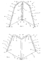
- the mobile shower splash guard 1 consists of two wings 3 and 4, by a steel tube frame 5 are bordered.
- This frame 5 forms the Form of a downwardly opening U and follows essentially three Sides of a trapezoid.
- the vertically extending leg 7 of the wing. 3 is by means of two vertically spaced double clamps. 9 made of plastic with the vertical leg 8 of the wing. 4 Both are referred to herein as inner legs 7 and 8.
- the each longer of the two parallel sides of the trapezoid represent the lower edges 11 and 12 of the wings 3 and 4 are dar.
- the inclined to the extending outer legs 17 and 19 fastened straps thirteenth bring the edge of the element 15 either in contact with the tubular frame 5 or position this edge close to the tube frame 5.
- To the horizontally extending tubular frame sections 21 and 22 and in particular to the outer legs 17 and 19 with the horizontally extending Tubular frame sections 21 and 22 connecting bends is the edge of the element 15 so far from the frame 5, that between element 15 and frame 5 passes 23 and 24 arise.
- the element 15 extends continuously from the outer leg 17 of the wing 3 on the two interconnected inner Legs 7 and 8 to the other outer leg 19 of the second wing 4.
- the downwardly facing pipe ends 25 of the frame 5 form the Support feet of the shower splash guard 1 and are equipped with plastic caps 27 Mistake.
- both wings 3 and 4 Due to the double clamps 9, both wings 3 and 4 against each other pivotable. This allows the shower splash guard 1 as flexible as possible to adapt to the respective room situation, since any angular positions between the wings 3 and 4 can be adjusted. To the Stowing the wings 3 and 4 can be placed in parallel. The shower splash guard 1 takes in this way a minimum volume of space one.
- the one-piece water-repellent element 15 can be - if it is made of textile material - remove for cleaning. To both wings 3 and 4 are placed against each other so that the Element 15 between two wings 3 and 4 is located. Then let yourself the straps 13 - possibly after removing the plastic caps 27th from the outer tube ends 25 - strip from the tubes 5.
- the straps 13 can also with Velcro be equipped so that stripping the straps 13 of the Pipes 5 is unnecessary and removing the water-repellent element 15 is simplified.
- the trapezoidal, widening downward contour of the wings 3 and 4 causes a shift of the center of gravity downwards. Furthermore the center of gravity is in a non-parallel position of the Wings 3 and 4 are defined within one of at least three points of support Triangle. This acts unintentionally tipping the shower splash guard 1, thus increasing security.
- the passages 23 and 24 allow easy handling of the shower splash guard 1 when adjusting the wings 3 and 4 and when moving or folding. Close the plastic caps 27 on the pipe ends 25 the cavity of the tubular frame 5 and act slipping the shower splash guard against.
Landscapes
- Health & Medical Sciences (AREA)
- Public Health (AREA)
- Epidemiology (AREA)
- General Health & Medical Sciences (AREA)
- Body Structure For Vehicles (AREA)
- Bathtubs, Showers, And Their Attachments (AREA)
Applications Claiming Priority (2)
| Application Number | Priority Date | Filing Date | Title |
|---|---|---|---|
| DE20316848U DE20316848U1 (de) | 2003-11-03 | 2003-11-03 | Duschspritzschutz |
| DE20316848U | 2003-11-03 |
Publications (2)
| Publication Number | Publication Date |
|---|---|
| EP1527726A2 true EP1527726A2 (fr) | 2005-05-04 |
| EP1527726A3 EP1527726A3 (fr) | 2005-07-27 |
Family
ID=34353543
Family Applications (1)
| Application Number | Title | Priority Date | Filing Date |
|---|---|---|---|
| EP04025974A Withdrawn EP1527726A3 (fr) | 2003-11-03 | 2004-11-02 | Pare-douche |
Country Status (2)
| Country | Link |
|---|---|
| EP (1) | EP1527726A3 (fr) |
| DE (1) | DE20316848U1 (fr) |
Families Citing this family (1)
| Publication number | Priority date | Publication date | Assignee | Title |
|---|---|---|---|---|
| DE102005042030A1 (de) * | 2005-09-02 | 2007-03-08 | Kludi Gmbh & Co. Kg | Duschabtrennungssystem |
Family Cites Families (10)
| Publication number | Priority date | Publication date | Assignee | Title |
|---|---|---|---|---|
| US3913598A (en) * | 1973-09-17 | 1975-10-21 | Jr Roy H Glutting | Hunter{3 s blind and shelter |
| DE7603207U1 (de) * | 1976-02-05 | 1976-08-19 | Kirchner, Alfred, 7600 Offenburg | Paravent |
| US4554937A (en) * | 1983-03-04 | 1985-11-26 | Irwin Dennis V | Portable shelter |
| US5544369A (en) * | 1994-09-16 | 1996-08-13 | Roberts; Ralph J. | Portable shower/multi use stall |
| US5469587A (en) * | 1994-12-20 | 1995-11-28 | Fendall Company | Portable emergency decontamination shower |
| US5722477A (en) * | 1995-10-31 | 1998-03-03 | The Children's Factory | Pipe connector assembly with internal locking mechanism |
| DE29703845U1 (de) * | 1997-03-04 | 1997-04-30 | Berger, Sigrid, 09247 Röhrsdorf | Duscheinrichtung |
| US5920927A (en) * | 1998-05-21 | 1999-07-13 | Thomas; John R. | Portable shower and toilet assembly |
| DE19942771A1 (de) * | 1999-09-08 | 2001-03-15 | Weis Albert | Schirmwand |
| US6293328B1 (en) * | 2000-08-03 | 2001-09-25 | Donna A. Fremont | Portable screen |
-
2003
- 2003-11-03 DE DE20316848U patent/DE20316848U1/de not_active Expired - Lifetime
-
2004
- 2004-11-02 EP EP04025974A patent/EP1527726A3/fr not_active Withdrawn
Also Published As
| Publication number | Publication date |
|---|---|
| EP1527726A3 (fr) | 2005-07-27 |
| DE20316848U1 (de) | 2005-03-17 |
Similar Documents
| Publication | Publication Date | Title |
|---|---|---|
| EP2179716B1 (fr) | Dispositif de transport pour patients | |
| DE2601020C3 (de) | Krankenhausstuhl | |
| WO2014135582A1 (fr) | Système mobile de protection contre les radiations | |
| DE102015100675B4 (de) | Verstellbarer Lattenrost | |
| CH694982A5 (de) | Aufrichtrollstuhl. | |
| DE2842102A1 (de) | Waschraum, insbesondere fuer koerperbehinderte personen | |
| DE3718440C2 (de) | Verkehrsbake | |
| EP1527726A2 (fr) | Pare-douche | |
| DE102007041037B3 (de) | Wickelkommode mit Absturzsicherung | |
| DE69113477T3 (de) | Stützvorrichtung. | |
| DE102009034016A1 (de) | Drehbettgestell | |
| DE3639799A1 (de) | Pflegewanne | |
| DE3028579A1 (de) | Katzenabort | |
| DE102014016966B4 (de) | Vorrichtung zur Lagerung von Säuglingen | |
| DE102005014637B3 (de) | Schwenkbare Beinstütze, insbesonder für Rollstühle | |
| EP2520462B1 (fr) | Véhicule | |
| DE102010050165A1 (de) | Vorrichtung zur Sicherung eines Patienten in einem Bett | |
| DE20218030U1 (de) | Kranken- oder Pflegebett | |
| DE3721857A1 (de) | Wasch- und pflegewanne | |
| DE202011106262U1 (de) | Duschsitz | |
| WO2013132039A1 (fr) | Double valve et écarteur chirurgical adapté à celle-ci | |
| DE8903105U1 (de) | Fingerring | |
| DE2702295B2 (de) | Einteilige Badewanne | |
| DE2064017B1 (de) | Bettseitenteil | |
| EP0747524A1 (fr) | Corbeille, en particulier corbeille à linge |
Legal Events
| Date | Code | Title | Description |
|---|---|---|---|
| PUAI | Public reference made under article 153(3) epc to a published international application that has entered the european phase |
Free format text: ORIGINAL CODE: 0009012 |
|
| AK | Designated contracting states |
Kind code of ref document: A2 Designated state(s): AT BE BG CH CY CZ DE DK EE ES FI FR GB GR HU IE IS IT LI LU MC NL PL PT RO SE SI SK TR |
|
| AX | Request for extension of the european patent |
Extension state: AL HR LT LV MK YU |
|
| PUAL | Search report despatched |
Free format text: ORIGINAL CODE: 0009013 |
|
| AK | Designated contracting states |
Kind code of ref document: A3 Designated state(s): AT BE BG CH CY CZ DE DK EE ES FI FR GB GR HU IE IS IT LI LU MC NL PL PT RO SE SI SK TR |
|
| AX | Request for extension of the european patent |
Extension state: AL HR LT LV MK YU |
|
| AKX | Designation fees paid | ||
| STAA | Information on the status of an ep patent application or granted ep patent |
Free format text: STATUS: THE APPLICATION IS DEEMED TO BE WITHDRAWN |
|
| 18D | Application deemed to be withdrawn |
Effective date: 20060128 |
|
| REG | Reference to a national code |
Ref country code: DE Ref legal event code: 8566 |