EP1526713A2 - Bildaufnahmegeràt - Google Patents
Bildaufnahmegeràt Download PDFInfo
- Publication number
- EP1526713A2 EP1526713A2 EP04010853A EP04010853A EP1526713A2 EP 1526713 A2 EP1526713 A2 EP 1526713A2 EP 04010853 A EP04010853 A EP 04010853A EP 04010853 A EP04010853 A EP 04010853A EP 1526713 A2 EP1526713 A2 EP 1526713A2
- Authority
- EP
- European Patent Office
- Prior art keywords
- image
- outputs
- addition pattern
- capturing
- addition
- Prior art date
- Legal status (The legal status is an assumption and is not a legal conclusion. Google has not performed a legal analysis and makes no representation as to the accuracy of the status listed.)
- Withdrawn
Links
Images




Classifications
-
- H—ELECTRICITY
- H04—ELECTRIC COMMUNICATION TECHNIQUE
- H04N—PICTORIAL COMMUNICATION, e.g. TELEVISION
- H04N25/00—Circuitry of solid-state image sensors [SSIS]; Control thereof
- H04N25/40—Extracting pixel data from image sensors by controlling scanning circuits, e.g. by modifying the number of pixels sampled or to be sampled
- H04N25/46—Extracting pixel data from image sensors by controlling scanning circuits, e.g. by modifying the number of pixels sampled or to be sampled by combining or binning pixels
Definitions
- the present invention relates to an image-capturing apparatus achieved by using a solid-state image-capturing element.
- Solid-state image-capturing apparatuses that improve the sensitivity by adding together electrical charges stored at adjacent pixels along the horizontal direction at a CCD solid-state image-capturing element and also minimize the extent of degradation of the horizontal resolution attributable to the addition include the one disclosed in Japanese Laid Open Patent Publication No. H 06-209434.
- Image signals are processed as described below in the image-capturing apparatus in the related art mentioned above.
- a reset pulse is applied to a reset gate of the CCD solid-state image-capturing element through intermittent drive over 2-pixel cycles and thus, the electrical charges stored at pixels adjacent to each other along the horizontal direction are mixed together to realize a sensitivity level twice as high.
- the extent to which the horizontal resolution is lowered is reduced to 3/4. However, it is inevitable that the resolution still becomes poorer.
- outputs of pixels located around a given pixel at an image-capturing unit are added to the output of that pixel before executing image processing on image signals output from the image-capturing unit having a plurality of pixels disposed two-dimensionally.
- An addition pattern with which pixel outputs are added together is determined in correspondence to the specific type of image processing to be executed and the pixel outputs constituting the image signals output from the image-capturing unit are added in conformance to the addition pattern to generate an image. Then, the image processing is executed on the image resulting from the addition and the image having undergone the image processing is output.
- the addition pattern may be determined in correspondence to a specific vehicular behavior.
- the pixel output addition pattern may be determined in correspondence to the extent of vibration that the image-capturing apparatus experiences.
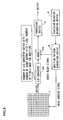
- FIG. 1 shows the structure adopted in an image-capturing apparatus achieved in the first embodiment.
- the image-capturing apparatus includes an image-capturing element 1, an adder 2, an A/D converter 3, an processing device 4 and an addition pattern generating device 5.
- the image-capturing element 1 is a semiconductor device adopting a CMOS structure which includes a plurality of light receiving elements disposed two-dimensionally and a read circuit that reads output voltages from the individual light receiving elements.
- the image-capturing element 1 outputs the output voltages from light receiving elements specified with read address signals as output voltages of the image-capturing element 1.
- the adder 2 adds the output signals from light receiving elements at addresses specified by the addition pattern generating device 5 which is to be detailed later until a reset signal is output from the addition pattern generating device 5. In other words, the adder 2 generates a new image by adding the outputs of pixels present around a given pixel at the image-capturing element 1 to the output from the pixel.
- the pixel outputs may be added together by weighting the outputs in correspondence to the individual light receiving elements instead of simply adding them together.
- the addition pattern generating device 5 may output weighting elements, or if weighting elements are fixed, the weighting elements may be automatically generated at the adder 2.
- the A/D converter 3 executes analog-digital conversion so as to enable digital processing of the output from the adder 2.
- the A/D converter 3 is achieved by using a device and circuits known in the related art.
- the processing device 4 executes image processing on the image-capturing signals having undergone the digital conversion to detect a vehicle present ahead, to detect the road conditions and the like. Such detections can be executed by adopting a method known in the related art.
- the processing device 4 also outputs information indicating the type of image processing to be executed to the addition pattern generating device 5. For instance, when executing longitudinal edge detection (vertical edge detection) through longitudinal Sobel filter arithmetic processing on 3 x 3 pixel data to detect a white line drawn on a road, a signal indicating that image processing for longitudinal edge detection is to be executed (hereafter referred to as an image processing type signal) is output to the addition pattern generating device 5.
- the addition pattern generating device 5 to which the image processing type signal is input from the processing device 4, generates a combination pattern or an addition pattern with which pixels are to be combined for the addition of the outputs thereof in correspondence to the processing type and outputs address signals specifying light receiving elements in correspondence to the addition pattern to the image-capturing element 1.
- the addition pattern generating device 5 outputs a reset signal to the adder 2 to initialize the adder 2.
- the combination pattern with which pixels are combined for the addition in correspondence to the type of image processing should be regarded as a pattern that will yield optimal results for a specific processing purpose, e.g., a pattern with which the outputs from three light receiving elements continuous along the lateral direction are added together or a pattern with which the outputs of every second light receiving element along the longitudinal direction for a total of four light receiving elements are added together.
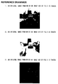
- FIGS. 2 to 5 show the results of image processing executed by using various sum image signals obtained in the image-capturing apparatus in the first embodiment.
- images 100, 200, 300 and 400 show the original image captured by the image-capturing element 1
- images 110, 210, 310 and 410 show a new image generated by adding the outputs of pixels present around a given pixel to the output of the pixel through a specific addition pattern at the adder 2
- images 120, 220, 320 and 420 show the results of a specific edge detection executed by the processing device 4 by using the new image.
- FIG. 2 shows the results of image processing executed by using the sums of outputs from pixels continuous along the longitudinal direction (vertical direction).
- a bright image can be obtained without lowering the resolution along the lateral direction (horizontal direction). For this reason, a bright and high-contrast image can be obtained even in an environment with a low level of illumination, e.g., night time.
- the outputs from pixels continuous along the longitudinal direction should be added together when, for instance, the processing device 4 is to execute image processing such as pedestrian detection in which a longitudinal edge component (a vertical edge component) of a target object needs to be extracted accurately.
- FIG. 3 shows the results of image processing executed by using the sums of outputs from pixels continuous along the lateral direction.
- the target object can be detected even when the level of illumination is low, without compromising the level of accuracy.
- FIG. 4 shows the results of image processing executed on image signals obtained by adding the outputs of pixels continuous in a " ⁇ " pattern.
- This addition pattern may be adopted when, for instance, the corners of a vehicle must be detected with a high degree of accuracy.
- FIG. 5 shows the results of image processing executed on image signals obtained by adding the outputs of pixels continuous in a " ⁇ " pattern.
- a bright image in which the characteristics of the " ⁇ " pattern are emphasized is generated.
- This addition pattern may be adopted when, for instance, a white line drawn diagonally on a road must be detected with a high degree of accuracy.
- the addition patterns are not limited to the longitudinal pattern, the lateral pattern, the " ⁇ ” pattern and the " ⁇ ” pattern shown in FIGS. 2 to 5.
- Various other patterns including, for instance, a "+” pattern, a "/ ⁇ ” pattern and " ⁇ ” pattern may be used.
- the outputs of pixels present in the vicinity of a given pixel at the image-capturing element 1 are added onto the output of the pixel.
- the addition is executed based upon the pixel output addition pattern determined in correspondence to the type of image processing to be executed.
- the different types of edges e.g., longitudinal edges, lateral edges, diagonal edges and a ⁇ -shaped edge, can be detected with a high degree of accuracy.
- the addition pattern may be altered for each frame of image output by the image-capturing element 1.
- the addition pattern may be switched for each frame by alternating between the longitudinal pattern and the lateral pattern.
- the processing device 4 should execute longitudinal edge extraction processing and lateral edge extraction processing in combination, each in correspondence to one of the addition patterns. It is particularly advantageous to change the addition pattern for each frame when an image-capturing element with a high frame rate is used. Since the time lag between the longitudinal addition and the lateral addition is reduced when the two types of processing are alternately executed repeatedly at a high frame rate, processing results equivalent to the results achieved by simultaneously extracting the longitudinal edges and the lateral edges with a high-sensitivity image are obtained.
- FIG. 6 presents another example of an image-capturing apparatus that adjusts the addition pattern in correspondence to the frame rate or the length of exposure time.
- the same reference numerals are assigned to components identical to those in the image-capturing apparatus shown in FIG. 1 to preclude the necessity for a repeated explanation thereof.
- Reference numeral 11 indicates a setting device that sets either a frame rate or a length of exposure time.
- the processing device 4 executes image processing for lateral edge detection, for instance, the number of pixels continuous along the lateral direction, the outputs of which are to be added together, can be adjusted in correspondence to the frame rate or the length of exposure time set by the setting device 11.
- the addition pattern as a lateral addition pattern, the number of pixels the outputs of which are added in the lateral addition pattern is adjusted in correspondence to the frame rate or the length of exposure time.
- the dynamic range can be expanded while achieving the required level of sensitivity to minimize the extent of deterioration of resolution.
- FIG. 7 shows another example of an image-capturing apparatus that adjusts the addition pattern in correspondence to the extent of vibration the image-capturing apparatus experiences.
- the same reference numerals are assigned to components identical to those in the image-capturing apparatus shown in FIG. 6 to preclude the necessity for a repeated explanation thereof.
- Reference numeral 21 indicates a vibration detection sensor that detects movement (vibration) of the optical axis of the image-capturing apparatus.
- the vibration detection sensor 21 detects the movement (vibration) of the optical axis of the image-capturing apparatus. Then, an addition pattern is generated so as to add together the outputs of pixels disposed continuously along a direction matching the detected direction, i.e., the direction along which the image blur or smear has occurred.
- the detection target image can be extracted with a high degree of sensitivity without lowering the resolution even when the optical axis of the image-capturing apparatus has shifted.
- FIG. 8 An image-capturing apparatus achieved in the second embodiment, which detects vehicular behavior and switches the pixel addition pattern in correspondence to the vehicular behavior, is explained in reference to FIG. 8.
- the same reference numerals are assigned to components and devices identical to those shown in FIG. 1 and the following explanation focuses on the differences.
- An A/D converter 3A executes analog - digital conversion to enable digital processing of the output of the image-capturing element 1.
- An adder 2A executes digital processing to add the output signals from light receiving elements at addresses specified by the addition pattern generating device 5 until a reset signal is output from the addition pattern generating device 5.
- signals output from the image-capturing element 1 immediately undergo the A/D conversion and are then added together through the digital processing.
- the output signals from the image-capturing element 1 may instead be added together through analog processing and the results of the addition may then undergo A/D conversion as in the first embodiment.
- a vehicular behavior measuring device 6 measures the vehicular behavior.
- a specific addition pattern type is determined based upon, for instance, information provided by a yaw rate sensor, which measures the vehicle motion along the yawing direction effected through steering and information provided by a vehicle height sensor which measures vertical movement of the vehicle. The addition pattern type thus determined is output to the addition pattern generating device 5.
- the image-capturing apparatus achieved in the second embodiment detects the vehicular behavior and generates the addition pattern corresponding to the vehicular behavior.
- the sensitivity under low illumination conditions can be improved while minimizing the extent of the deterioration of the resolution.
- the addition pattern is adjusted based upon the vehicular behavior.
- This addition pattern adjustment may be adopted in conjunction with the addition pattern adjustment based upon the type of image processing having been explained in reference to the first embodiment and the examples of variations.
- the image-capturing apparatus according to the present invention is used in a vehicle both in the first embodiment and in the second embodiment described above.
- the present invention may be adopted in all types of applications other than automotive applications, as well.
- it may be adopted in an image-capturing apparatus for a robot that detects the position of an object.
Landscapes
- Engineering & Computer Science (AREA)
- Multimedia (AREA)
- Signal Processing (AREA)
- Image Processing (AREA)
- Transforming Light Signals Into Electric Signals (AREA)
- Studio Devices (AREA)
Applications Claiming Priority (4)
| Application Number | Priority Date | Filing Date | Title |
|---|---|---|---|
| JP2003142536 | 2003-05-20 | ||
| JP2003142536 | 2003-05-20 | ||
| JP2004072530A JP4228947B2 (ja) | 2003-05-20 | 2004-03-15 | 撮像装置 |
| JP2004072530 | 2004-03-15 |
Publications (2)
| Publication Number | Publication Date |
|---|---|
| EP1526713A2 true EP1526713A2 (de) | 2005-04-27 |
| EP1526713A3 EP1526713A3 (de) | 2008-09-17 |
Family
ID=33455523
Family Applications (1)
| Application Number | Title | Priority Date | Filing Date |
|---|---|---|---|
| EP04010853A Withdrawn EP1526713A3 (de) | 2003-05-20 | 2004-05-06 | Bildaufnahmegeràt |
Country Status (3)
| Country | Link |
|---|---|
| US (1) | US7421091B2 (de) |
| EP (1) | EP1526713A3 (de) |
| JP (1) | JP4228947B2 (de) |
Cited By (2)
| Publication number | Priority date | Publication date | Assignee | Title |
|---|---|---|---|---|
| EP3562145A1 (de) * | 2018-04-25 | 2019-10-30 | Bayerische Motoren Werke Aktiengesellschaft | Verfahren und vorrichtung zum betrieb eines fortschrittlichen fahrerassistenzsystems eines fahrzeugs |
| US10778881B2 (en) | 2014-01-09 | 2020-09-15 | Sony Corporation | Video signal processing device, video signal processing method, and camera device |
Families Citing this family (6)
| Publication number | Priority date | Publication date | Assignee | Title |
|---|---|---|---|---|
| US7714890B2 (en) * | 2005-04-26 | 2010-05-11 | Olympus Imaging Corp. | Image pickup apparatus and method for controlling pixel reading using a shake determination |
| US7705900B2 (en) * | 2005-06-01 | 2010-04-27 | Eastman Kodak Company | CMOS image sensor pixel with selectable binning and conversion gain |
| WO2010104969A1 (en) * | 2009-03-11 | 2010-09-16 | Zoran Corporation | Estimation of point spread functions from motion-blurred images |
| CN102511046B (zh) | 2009-12-02 | 2015-03-25 | 塔塔咨询服务有限公司 | 使用近红外照相机对行人进行检测、分类并追踪的有成本效益的系统及方法 |
| JP5868090B2 (ja) | 2011-09-20 | 2016-02-24 | 三菱電機株式会社 | 画像処理装置、画像処理方法、撮像装置、コンピュータプログラム及びコンピュータ読み取り可能な記録媒体 |
| JP2018148582A (ja) * | 2013-10-24 | 2018-09-20 | パナソニックIpマネジメント株式会社 | 撮像システム、撮像装置、符号化装置、および撮像方法 |
Citations (3)
| Publication number | Priority date | Publication date | Assignee | Title |
|---|---|---|---|---|
| EP0717557A2 (de) * | 1994-12-15 | 1996-06-19 | NOKIA TECHNOLOGY GmbH | Vorrichtung und Gerät zum Hervorheben der Umrisse in einen Videobild |
| EP0964584A1 (de) * | 1993-12-22 | 1999-12-15 | Eastman Kodak Company | Elektronische Kamera mit sequentieller Farbaufnahme |
| US20020172431A1 (en) * | 2001-03-07 | 2002-11-21 | Atkins C. Brian | Digital image appearance enhancement and compressibility improvement method and system |
Family Cites Families (34)
| Publication number | Priority date | Publication date | Assignee | Title |
|---|---|---|---|---|
| US7164117B2 (en) * | 1992-05-05 | 2007-01-16 | Automotive Technologies International, Inc. | Vehicular restraint system control system and method using multiple optical imagers |
| IL83213A (en) * | 1987-07-16 | 1991-08-16 | Technion Res & Dev Foundation | Intelligent scan image sensor |
| US5262871A (en) * | 1989-11-13 | 1993-11-16 | Rutgers, The State University | Multiple resolution image sensor |
| JP2642807B2 (ja) | 1991-08-20 | 1997-08-20 | 三洋電機株式会社 | 固体撮像装置 |
| JP2642810B2 (ja) | 1991-08-29 | 1997-08-20 | 三洋電機株式会社 | 固体撮像装置 |
| US5903454A (en) * | 1991-12-23 | 1999-05-11 | Hoffberg; Linda Irene | Human-factored interface corporating adaptive pattern recognition based controller apparatus |
| JPH0662325A (ja) | 1992-08-11 | 1994-03-04 | Toshiba Corp | 固体撮像素子を使用した撮像装置 |
| JPH0763181B2 (ja) | 1993-01-11 | 1995-07-05 | 日本電気株式会社 | 固体撮像装置 |
| JP3130699B2 (ja) | 1993-03-29 | 2001-01-31 | 日本放送協会 | 固体撮像装置 |
| JP2817581B2 (ja) | 1993-08-02 | 1998-10-30 | 日本電気株式会社 | 固体撮像装置 |
| JP2891880B2 (ja) | 1994-08-31 | 1999-05-17 | 日本電気株式会社 | 固体撮像装置 |
| JP2907268B2 (ja) | 1995-07-03 | 1999-06-21 | キヤノン株式会社 | 信号処理装置と固体撮像装置とこの装置の撮像方法 |
| JPH08307774A (ja) | 1995-05-12 | 1996-11-22 | Nec Corp | カラーカメラ |
| US7147246B2 (en) * | 1995-06-07 | 2006-12-12 | Automotive Technologies International, Inc. | Method for airbag inflation control |
| JP3031606B2 (ja) | 1995-08-02 | 2000-04-10 | キヤノン株式会社 | 固体撮像装置と画像撮像装置 |
| JP3123415B2 (ja) | 1995-12-25 | 2001-01-09 | 日本電気株式会社 | 単板カラー固体撮像装置 |
| JPH09322057A (ja) * | 1996-05-28 | 1997-12-12 | Canon Inc | 撮像装置 |
| US6011531A (en) * | 1996-10-21 | 2000-01-04 | Xerox Corporation | Methods and applications of combining pixels to the gate and data lines for 2-D imaging and display arrays |
| JPH10200908A (ja) | 1997-01-10 | 1998-07-31 | Sanyo Electric Co Ltd | 固体撮像装置 |
| JP3485746B2 (ja) | 1997-01-31 | 2004-01-13 | 三洋電機株式会社 | 固体撮像装置 |
| JPH1155575A (ja) | 1997-08-06 | 1999-02-26 | Sony Corp | 固体撮像装置 |
| JPH1169210A (ja) | 1997-08-26 | 1999-03-09 | Fuji Electric Co Ltd | ラインセンサカメラ |
| US6229578B1 (en) * | 1997-12-08 | 2001-05-08 | Intel Corporation | Edge-detection based noise removal algorithm |
| JPH11298800A (ja) | 1998-04-10 | 1999-10-29 | Nikon Corp | 撮像素子およびこれを用いた撮像装置 |
| JP2000069491A (ja) | 1998-08-19 | 2000-03-03 | Nikon Corp | 撮像素子およびこれを用いた撮像装置 |
| JP4196029B2 (ja) | 1998-04-10 | 2008-12-17 | 株式会社ニコン | 撮像回路および撮像装置 |
| JP4077120B2 (ja) | 1999-07-01 | 2008-04-16 | 富士フイルム株式会社 | 固体撮像装置および信号処理方法 |
| JP3636291B2 (ja) | 2000-01-31 | 2005-04-06 | オリンパス株式会社 | 撮像装置 |
| JP2001285719A (ja) | 2000-03-31 | 2001-10-12 | Omron Corp | 撮像装置 |
| JP2002010140A (ja) | 2000-06-19 | 2002-01-11 | Olympus Optical Co Ltd | 撮像装置 |
| US6968073B1 (en) * | 2001-04-24 | 2005-11-22 | Automotive Systems Laboratory, Inc. | Occupant detection system |
| JP3846572B2 (ja) * | 2001-09-20 | 2006-11-15 | ソニー株式会社 | 固体撮像装置 |
| US6794627B2 (en) * | 2001-10-24 | 2004-09-21 | Foveon, Inc. | Aggregation of active pixel sensor signals |
| US6778766B2 (en) * | 2002-01-25 | 2004-08-17 | Nikon Corporation | Vibration detection device and vibration correcting optical device |
-
2004
- 2004-03-15 JP JP2004072530A patent/JP4228947B2/ja not_active Expired - Fee Related
- 2004-04-22 US US10/829,383 patent/US7421091B2/en not_active Expired - Lifetime
- 2004-05-06 EP EP04010853A patent/EP1526713A3/de not_active Withdrawn
Patent Citations (3)
| Publication number | Priority date | Publication date | Assignee | Title |
|---|---|---|---|---|
| EP0964584A1 (de) * | 1993-12-22 | 1999-12-15 | Eastman Kodak Company | Elektronische Kamera mit sequentieller Farbaufnahme |
| EP0717557A2 (de) * | 1994-12-15 | 1996-06-19 | NOKIA TECHNOLOGY GmbH | Vorrichtung und Gerät zum Hervorheben der Umrisse in einen Videobild |
| US20020172431A1 (en) * | 2001-03-07 | 2002-11-21 | Atkins C. Brian | Digital image appearance enhancement and compressibility improvement method and system |
Non-Patent Citations (2)
| Title |
|---|
| DATASHEET: "Mitsubishi Integrated Circuit M64282FP Image Sensor (Artificial Retina LSI)", 21 May 1998 (1998-05-21), XP055731176, Retrieved from the Internet <URL:https://people.ece.cornell.edu/land/courses/ece4760/FinalProjects/f2012/qs44_twc55/qs44_twc55/datasheets/MITSUB_image_sensor.pdf> [retrieved on 20200916] * |
| ROBERTSON P ET AL: "ADAPTIVE IMAGE ANALYSIS FOR AERIAL SURVEILLANCE", IEEE INTELLIGENT SYSTEMS, IEEE SERVICE CENTER, NEW YORK, NY, US, vol. 14, no. 3, 1 May 1999 (1999-05-01), pages 30 - 36, XP000851501, ISSN: 1094-7167, DOI: 10.1109/5254.769882 * |
Cited By (2)
| Publication number | Priority date | Publication date | Assignee | Title |
|---|---|---|---|---|
| US10778881B2 (en) | 2014-01-09 | 2020-09-15 | Sony Corporation | Video signal processing device, video signal processing method, and camera device |
| EP3562145A1 (de) * | 2018-04-25 | 2019-10-30 | Bayerische Motoren Werke Aktiengesellschaft | Verfahren und vorrichtung zum betrieb eines fortschrittlichen fahrerassistenzsystems eines fahrzeugs |
Also Published As
| Publication number | Publication date |
|---|---|
| US20040233300A1 (en) | 2004-11-25 |
| EP1526713A3 (de) | 2008-09-17 |
| JP2005006283A (ja) | 2005-01-06 |
| US7421091B2 (en) | 2008-09-02 |
| JP4228947B2 (ja) | 2009-02-25 |
Similar Documents
| Publication | Publication Date | Title |
|---|---|---|
| US8509481B2 (en) | Image processing apparatus, image processing method, imaging apparatus | |
| US11303830B2 (en) | Photoelectric conversion device and imaging system | |
| US20090079862A1 (en) | Method and apparatus providing imaging auto-focus utilizing absolute blur value | |
| CN112740659A (zh) | 固态摄像元件和摄像装置 | |
| CN102667862B (zh) | 用于借助hdr摄像机确定相对运动的方法 | |
| US11196956B2 (en) | Solid-state image sensor, imaging device, and method of controlling solid-state image sensor | |
| US20190182458A1 (en) | Imaging device and imaging system | |
| CN103914810A (zh) | 用于动态后视镜的图像超分辨率 | |
| JPH07115643A (ja) | 車載用撮像装置 | |
| KR940013150A (ko) | 움직임 벡터 검출 장치 및 고체 촬상 장치 | |
| US7421091B2 (en) | Image-capturing apparatus | |
| JP2008060873A (ja) | 複数画角カメラ | |
| KR102785697B1 (ko) | 동영상 처리 장치 및 동영상 처리 방법 | |
| US12526537B2 (en) | Imaging apparatus, depth map generation method, and program | |
| JP2007293672A (ja) | 車両用撮影装置、車両用撮影装置の汚れ検出方法 | |
| US8704943B2 (en) | Systems for multi-exposure imaging | |
| JPH04309078A (ja) | ビデオデータの動き検出装置および方法 | |
| JP5230362B2 (ja) | 広ダイナミックレンジ撮像装置 | |
| CN110710200B (zh) | 摄像器件、摄像设备和移动体 | |
| JP2023005320A (ja) | 動き情報撮像装置 | |
| JP2008042227A (ja) | 撮像装置 | |
| Yamada et al. | Effectiveness of video camera dynamic range expansion for lane mark detection | |
| JP4039648B2 (ja) | 特定路線バス検出方法およびその装置 | |
| JP4114633B2 (ja) | 画像処理装置および方法 | |
| JP4086025B2 (ja) | 動き検出装置及び方法 |
Legal Events
| Date | Code | Title | Description |
|---|---|---|---|
| PUAI | Public reference made under article 153(3) epc to a published international application that has entered the european phase |
Free format text: ORIGINAL CODE: 0009012 |
|
| 17P | Request for examination filed |
Effective date: 20040507 |
|
| AK | Designated contracting states |
Kind code of ref document: A2 Designated state(s): AT BE BG CH CY CZ DE DK EE ES FI FR GB GR HU IE IT LI LU MC NL PL PT RO SE SI SK TR |
|
| AX | Request for extension of the european patent |
Extension state: AL HR LT LV MK |
|
| PUAL | Search report despatched |
Free format text: ORIGINAL CODE: 0009013 |
|
| AK | Designated contracting states |
Kind code of ref document: A3 Designated state(s): AT BE BG CH CY CZ DE DK EE ES FI FR GB GR HU IE IT LI LU MC NL PL PT RO SE SI SK TR |
|
| AX | Request for extension of the european patent |
Extension state: AL HR LT LV MK |
|
| AKX | Designation fees paid |
Designated state(s): DE FR GB |
|
| 17Q | First examination report despatched |
Effective date: 20090429 |
|
| STAA | Information on the status of an ep patent application or granted ep patent |
Free format text: STATUS: EXAMINATION IS IN PROGRESS |
|
| RIC1 | Information provided on ipc code assigned before grant |
Ipc: H04N 5/347 20110101AFI20201118BHEP |
|
| GRAP | Despatch of communication of intention to grant a patent |
Free format text: ORIGINAL CODE: EPIDOSNIGR1 |
|
| STAA | Information on the status of an ep patent application or granted ep patent |
Free format text: STATUS: GRANT OF PATENT IS INTENDED |
|
| INTG | Intention to grant announced |
Effective date: 20210104 |
|
| INTG | Intention to grant announced |
Effective date: 20210113 |
|
| STAA | Information on the status of an ep patent application or granted ep patent |
Free format text: STATUS: THE APPLICATION IS DEEMED TO BE WITHDRAWN |
|
| 18D | Application deemed to be withdrawn |
Effective date: 20210526 |