EP1526198A2 - Webschaft mit neuartigem Eckverbinder - Google Patents
Webschaft mit neuartigem Eckverbinder Download PDFInfo
- Publication number
- EP1526198A2 EP1526198A2 EP04020968A EP04020968A EP1526198A2 EP 1526198 A2 EP1526198 A2 EP 1526198A2 EP 04020968 A EP04020968 A EP 04020968A EP 04020968 A EP04020968 A EP 04020968A EP 1526198 A2 EP1526198 A2 EP 1526198A2
- Authority
- EP
- European Patent Office
- Prior art keywords
- pin
- shaft rod
- holding
- piece
- cavity
- Prior art date
- Legal status (The legal status is an assumption and is not a legal conclusion. Google has not performed a legal analysis and makes no representation as to the accuracy of the status listed.)
- Granted
Links
Images


Classifications
-
- D—TEXTILES; PAPER
- D03—WEAVING
- D03C—SHEDDING MECHANISMS; PATTERN CARDS OR CHAINS; PUNCHING OF CARDS; DESIGNING PATTERNS
- D03C9/00—Healds; Heald frames
- D03C9/06—Heald frames
- D03C9/0666—Connection of frame parts
- D03C9/0675—Corner connections between horizontal rods and side stays
-
- D—TEXTILES; PAPER
- D03—WEAVING
- D03C—SHEDDING MECHANISMS; PATTERN CARDS OR CHAINS; PUNCHING OF CARDS; DESIGNING PATTERNS
- D03C9/00—Healds; Heald frames
- D03C9/06—Heald frames
- D03C9/0691—Arrangements of means for damping or noise reduction
Definitions
- the invention relates to a weaving shank for weaving machines.
- Web shafts are used on weaving machines for example Specialist education used. They have an upper and a lower shaft rod on, which at their ends by side supports connected to each other.
- the upper and the lower Shaft rods are provided with Litzentragschienen on which the healds held in large numbers parallel to each other are.
- healds When setting up the loom, for example because of article change, healds occasionally need off taken out of the machine. It is for example also required to change healds dismantle the heald frames by removing the side supports from the shaft rods are removed.
- the weaving shed is subject a strong vibration load. This may not at any Place of the heald, not even at the ends of the heald, to material cracks, vibration breaks and the like to lead:
- From DE 196 12 404 A1 is a weave with detachable Corner joints between the side support and the Shaft rod known. At each corner joint is in the concerned cavity a corner connector used with the side wall of the cavity formed in the shaft rod riveted. In a recess of the corner connector occurs a provided on the side support pin-like projection a, in this recess by a clamping screw is secured. After loosening the clamping screw The side support can be removed.
- connection between Shaft rod and side support for rebarless reefers Shank-strand system known.
- the connection includes one inserted in the cavity of the shaft rod connector with a recess for receiving one on the side support provided pin. This pin enters Intermediate piece of plastic and engages with said in said Recess.
- a longitudinally passing through the pin fastening screw finds its anchoring in a threaded piece, in the inserted into the cavity of the shaft rod Connector sits.
- the connector points a certain mobility in the cavity in the lateral support longitudinal direction on, being in one direction through two Compressed springs is supported. At the top it is through a screw supported, with which the exact position of the Connector is adjustable. With this measure you can adjust the play on the lead.
- the weaving shank according to the invention has a connecting piece on, in the open end cavity of the Inserted shaft rod and secured there latching can. It is literally clipped, for which neither special knowledge still special tools are required. E-ckentagenen can be made quickly and easily become. Is the connector made of plastic It can also act as a dampener. It can be manufactured as a one-piece plastic injection molded part, so that there are low production costs.
- the connector is with respect.
- the Power transmission can by contact surfaces of the intermediate piece be moved, which arranged adjacent to the latch are.
- On the opposite side is as a means for supporting the connecting piece, preferably a spring means intended.
- a clamping piece be used with an externally operated Clamping screw is provided and against the locking lug opposite lying side of the connector presses to to clamp this.
- the clamping piece points to his Top side a contact surface for the inside of the web of the shaft rod and a threaded hole in which the Clamping screw is seated.
- the power transmission is done by it a large area.
- the connector the pin encompassing holding pieces on their ends are provided with spring means. These form a resilient system for the side support, what the vibration resistance the connection increases and also otherwise is considered advantageous.
- the Detent opening is a passage opening through which the detent is visible from the outside.
- This has the advantage that e.g. differently colored connectors kept ready and can be seen from the outside at a glance is what color the connector has.
- the establishment of weaving machines is essential facilitated.
- the lower strand games adjust while in long shafts differently colored Connectors may be present, the larger Litzenastronom to adjust.
- this is a supply various connectors kept ready.
- the connector or the intermediate piece is designed so that they Keep the pins away from the side walls of the shaft rod. This can be done by positive locking between the connector or the intermediate piece on the one hand and the pin on the other done, the pin in the transverse direction (measured perpendicular to the sidewalls of the shaft rod) is thinner as the clear width of the cavity.
- the connector and / or the intermediate piece, on the other hand, is supported on the side walls of the cavity and thus keeps the pin of the side walls of the shaft rod away.
- the pin centered in the cavity.
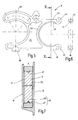
- FIG. 1 illustrates a heddle 1, to which an upper shaft rod 2, a lower shaft rod 3 and two side supports 4, 5 belong.
- the shaft rods 2, 3 are through the side supports 4, 5 at their ends with each other connected and thereby parallel and at a distance from each other held.
- Both shaft rods 2, 3 wear, as in the example of the shaft rod 2 of Figure 2 can be seen, one each Litzentragschiene 6, on the several strands 7 with their end loops are held.
- Figure 1 heald 1 is distinguished in particular by the nature of the connection between the Shaft rods 2, 3 and the side supports 4, 5 off. These Connection is representative of all four corner joints illustrated in FIG.
- Essential element of the corner joint forms a connector 8, by a plastic injection molding element can be formed. It is in a cavity 9 of the shaft rod 2 used, the top and bottom by a Web 11, 12 and by side walls 13, 14 is limited and preferably has an approximately rectangular cross-section.
- the shaft rod 2 may include one or more such cavities exhibit.
- the cross section of the cavity 9 has preferably a width (in Figure 2 perpendicular to the plane of the drawing) which is much smaller than its height. The Height is the distance between the webs 11 and 12. It is in Figure 2 parallel to the plane in the vertical direction shown.
- the connecting piece 8 is for example a shaped body, the one on his bottom one over his whole Length extending and the width of the web 12 engaging Plate or rib 15 has. She goes to her side bolster 5 facing end in a leg 16 via, which, as will be seen, for the storage of an on the Side support 5 molded pin 17 is used.
- the rib 15 carries at its end remote from the leg 16 a Locking lug 18, over the lower, the rib 15 limiting Plan face protrudes down and into one in the Bridge 12 trained detent opening 19 engages.
- the rib 15 is made from the locking lug 18th with an initially u-shaped and then in the opposite direction c-shaped bent portion 21 in the direction of the web eleventh away.
- this section 22 of the rib 15 leads to an upper portion of the same, which in turn forms a leg 23.
- the thigh 16, 23 and the section 22 thus define a mouth-like Receiving opening for the pin 17.
- the connector 8 preferably one piece with the rib 15th formed plate 24 is arranged.
- the spring section 26 is arched towards the web 11, to abut on this with a bend 28.
- a clamping piece 29 For further connection between the shaft rod 2 and the side support 5 is a clamping piece 29, which by a U-shaped bent metal bracket is formed. His upper, on the web 11 abutting leg has a threaded hole 31, in which a clamping screw 32 is seated. These supports with its front end to the lower Leg of the clamping piece 29 from which on the leg 23rd rests. By the way, it passes through the upper web 11 at one Through hole 33, so that her head 34 outside of the shaft rod 2 is located.
- the pin 17 is formed substantially disc-shaped. Its width measured perpendicular to the plane of the drawing is less than the inside width of the cavity 9. At his the side walls 13, 14 facing flanks he is with Plane surfaces 51, 52 ( Figure 7) provided while he to his the legs 16, 23 facing sides barrel-shaped or arcuately arched. Between thighs 16, 23 and the pin 17 is preferably a spacer 35, the is illustrated separately in Figure 3. It points inside a pin 17 adapted and outside one of the legs 16, 23 and the section 22 adapted contour. in the Principle it is formed ⁇ -shaped. His upper thigh 36 and its lower leg 37 may be the same or as in Figure 3 illustrates having different heights X, Y.
- the shaft rod 2 if this has not happened yet, first with the detent opening 19 provided in which, the latching opening 19 as Figure 2 illustrates in the lower bridge 12 and, as dashed lines illustrates, possibly in one of the side walls, e.g. the Side wall 14 is introduced by means of milling operation.
- the Detent opening 19 is, as far as it passes through the web 12, rectangular.
- the in the side wall 14th extending part forms a viewing window.
- the connector 8 is in the cavity together with the clamping piece 29 9 introduced, wherein the spring portion 26 yields downward and the detent 18 slides on the web 12 along until it finds in the locking opening 19. Under the effect of Spring section 26 engages the latching lug 18 in the latching opening 19 one.
- the intermediate piece 35 is preferably not one formed to hard, somewhat resilient and cushioning plastic, so that a vibration-absorbing compound created between the shaft rod 2 and the side support 5 is.
- the power transmission essentially takes place by means of the webs 11, 12, the clamping piece 29, the pin 17 and of thigh 16 instead. A local weakening of the side support 5 or the shaft rod 2 is not recorded.
- the connector When disassembling the side support 5, the connector remains 8 in the shaft rod 2. Only to change the Litzenspiels, if no intermediate piece 35 is present the connector 8 through another connector. 8 be replaced with deviating embodiment. Is a Intermediate piece 35 is present on the pin 17th the side support 5 is mounted, or clamped held, and is used to change the Litzenspiels by another Substitute 35 replaced with deviating embodiment.
- FIG. 4 illustrates a modified embodiment of the heald 1 and its corner joint.
- the connecting piece 8 encloses a circular arc limited pin 17 without interposition of an intermediate piece. That of the legs 16, 23 and the section 22nd bounded mouth follows a circular arc. As in particular from 5 shows, the free ends of the legs 16, 23 with bending springs, with a small radius provided in an arc-shaped bent contact sections 42, 43, according to Figure 4, the side support 5 resiliently supported.
- the upper spring portion 26 of the connector 8 as the opening 27 formed in a circular arc.
- the spring portion 26 forms a detent 18 in the detent opening 19 retaining spring.
- FIG. 6 A significant feature of the connector 8 is apparent from Figure 6.
- the pin 17 On the inner contour of the legs 16, 23 and, if necessary, also on the section 22 is preferably centered a rib 47 formed in the bounded Interior protrudes. The function of the same is off Figure 7 can be seen.
- the pin 17 is at its outer periphery provided with a groove 48 that is just so big that they can take the rib 47 play with little play.
- the between its flat sides 51, 52 measured width of the pin 17th is also much smaller than the inside width of the Cavity 9.
- the flat sides 51, 52 are thereby at a distance held parallel to the side walls 13, 14.
- the rib 47 and the groove 48 form thus a form-fitting acting means 49 for alignment of the pin 17.
- the connectors described above have each a detent 18 and an associated spring means e.g. in the form of the spring section 26. It is, however, how schematically indicated in Figure 8, also possible, two locking lugs 18a, 18b provided, for example, at parallel aligned, slightly resilient legs 53, 54th of the connecting piece 8 are held. As FIG. 9 illustrates, it is sufficient if only one of the legs 53, 54 is provided with the locking lug 18. It is next possible, latching lugs on the flanks of the connecting piece. 8 to arrange, as is apparent from Figure 10. According to this embodiment can be on one or both sides of the flat Connecting piece 8 a locking means in the form of a latching tongue Be provided 55, which then in a corresponding detent opening engages in the associated side wall 13 or 14.
- FIG. 11 out Another embodiment of the corner joint between the shaft rod 2 and the side support 5 is shown in FIG. 11 out.
- the connecting piece 8 comes without locking means out.
- the side walls 13, 14 are round with each other aligned through holes 56 provided in which a cylindrical armature 57 is seated.
- the pin 17 on the Intermediate piece 35 is held, is also with a Transverse bore 58 provided in a cylindrical with a arranged transversely threaded hole 59 provided anchor is.
- a threaded bolt 61 passes through the anchor 57, relies on this and is with the threaded hole screwed the armature 59, thereby the side support 5 to pull against the shaft rod 2.
- the threaded bolt 61 For operation of the threaded bolt 61 is at least the side wall 13, preferably but both the side wall 13 and the side wall 14, each with an elongated access opening 62 Mistake. This provides access to the head of the threaded bolt 61.
- the connecting piece 8 fills the cavity 9 off.
- Its circumferential rib 15 is both at the bottom the web 12 and the top of the web 11 at.
- the thigh 16, 23 are located on the webs 12, 11 at.
- both the illustrated connector 8 as well as the Adapter 35 in dimensionally different designs be kept ready.
- the differences only relate on the thicknesses of the legs 16, 23, 36, 37.
- the clear width between two legs 16, 23 and 36, 37 is in these cases always the same and the enclosed contour in each case coincides with the contour of the pin 17.
- Due to the different leg thicknesses the different Connectors 8 and the various intermediate pieces 35 but different relative positions between the pin 17 and the webs 11, 12, so that when using different connecting or intermediate pieces 8, 35 the distances between the shaft rods 2, 3 can be changed in stages. This may be for adjustment of the Litzenspiels are used.
- that illustrated in Figure 11 connector (spacer) 8 can be made slightly asymmetrical, so that a turn by 180 ° around the schematically registered Axis 63 causes a change in the Litzenspiels.
- Figure 12 illustrates different embodiments of intermediate pieces 35a, 35b, 35c, 35d, 35e, 35f.
- the spacers can be symmetrical as the intermediate pieces 35a, 35b, 35c, 35d or 35e or alternatively asymmetrical as the intermediate piece 35f formed be.
- the asymmetry exists here in different thicknesses the leg 36f, 37f.
- the legs 36a, 37a form as spring elements.
- These can be the thighs 36a, 37a have an increased thickness and recesses, the the legs 36a, 37a a compressibility in the longitudinal direction give the side support 5.
- the contact sections 42, 43 differently form resilient, as in the intermediate pieces 35b, 35c, 35d, 35e, based on the plant sections 42b, 42c, 42d, 42e and 43b, 43c, 43d, 43e. It can thereby different spring hardness and Damping effects can be achieved.
- FIG. 13 illustrates another alternative to FIG Possibilities of designing form-fitting, the pin 17 centering or otherwise from the side walls 13, 14 remote means.
- the pin 17a, 17b a have smooth outer peripheral surface.
- the Pintle 17a are e.g. on the flat sides 51a, 51b adjacent Finger 64, 65 provided extending from the section 22nd of the connecting piece 8 extend away. It is also possible, the legs 16b, 23b and 36, 37 with the flat sides 51b, 52b provide overarching edges.
- the thigh 16c, 23c and 36, 37 may also have a trapezoidal shape Have cross-section, wherein the pin 17c then a triangular has round running groove.
- the configuration can also be met vice versa, as based on the thighs 16d, 23d and 36, 37 and the associated pin 17d can be seen is.
- one on the pin 17 e circumferential Rectangular groove or on the pin 17f a circumferential rib be provided, wherein the legs 16e, 23e and 16f, 23f are each formed complementary.
- the pins 17 by no means barrel-shaped or be formed rectangular. As FIG. 14 illustrates, the most diverse shaped pin 17g to 17k come into application, the one form fit between them and a correspondingly complementarily shaped intermediate piece 35 or a complementarily shaped connector 8 allow.
- FIG. 15 Another aspect of the invention is in use a set of connectors 8 with different Thigh measurements or, as Figure 15 shows, a sentence 66 consisting of spacers 35, 35-1, 35-2, 35-3, the matching outer contours and matching inner contours, but different thickness leg 36, 37th exhibit.
- the intermediate pieces 35 of the sentence 66 preferably have different distinctive Means, e.g.
- the intermediate pieces can be made visually distinguishable to the mounting position to recognize at a glance.
- Identification means e.g. a score 50, 50-1, 50-2, 50-3 be formed, whose position identifies the leg thicknesses.
- the same or similar means can at the Connector for dimensional marking intended become.
- a novel corner connector for heddle shafts has locking means 18, 26, with which he in a shaft rod 2 can be held.
- the load-locking takes place independent of the locking means by a clamping device, which acts between the webs 11, 12 of the shaft rod 2.
Landscapes
- Engineering & Computer Science (AREA)
- Textile Engineering (AREA)
- Looms (AREA)
- Clamps And Clips (AREA)
- Mutual Connection Of Rods And Tubes (AREA)
Abstract
Description
- Figur 1
- einen Webschaft in schematisierter Vorderansicht,
- Figur 2
- den Webschaft nach Figur 1 in einer ausschnittsweisen, teilweise geschnittenen Darstellung in einem anderen Maßstab,
- Figur 3
- ein Zwischenstück der aus Figur 2 hervorgehenden Eckverbindung in gesonderter Darstellung,
- Figur 4
- eine abgewandelte Ausführungsform eines Webschafts in ausschnittsweiser, teilweise geschnittener Darstellung,
- Figur 5
- ein Verbindungsstück des Webschafts nach Figur 4 in Vorderansicht,
- Figur 6
- das Verbindungsstück nach Figur 5, geschnitten entlang der Linie VI-VI,
- Figur 7
- den Webschaft nach Figur 4, geschnitten entlang der Linie VII-VII,
- Figur 8 bis 10
- Verbindungsstücke für Webschäfte in unterschiedlichen Ausführungsformen, jeweils in Seitenansicht,
- Figur 11
- eine weitere Ausführungsform eines Webschafts in schematisierter Seitenansicht und ausschnittsweiser - Darstellung,
- Figur 12
- unterschiedliche Ausführungsformen von Zwischenstücken für Webschäfte und zum Einsatz in entsprechenden Verbindungsstücken, jeweils in schematisierter Darstellung,
- Figur 13
- unterschiedliche Ausführungsformen von Zapfen und Zwischenstücken bzw. Verbindungsstücken, jeweils entsprechend der Schnittdarstellung gemäß Figur 7,
- Figur 14
- unterschiedliche Ausführungsformen von Seitenstützen und deren Haltezapfen in jeweils schematisierter Seitenansicht und
- Figur 15
- einen Satz Zwischenstücke für unterschiedliche Litzenspiele in schematisierter Seitenansicht.
- 1
- Webschaft
- 2, 3
- Schaftstab
- 4, 5
- Seitenstützen
- 6
- Litzentragschiene
- 7
- Litzen
- 8
- Verbindungsstück, (Haltestück)
- 9
- Hohlraum
- 11, 12
- Steg
- 13, 14
- Seitenwände
- 15
- Rippe
- 16
- Schenkel
- 17
- Zapfen
- 18
- Rastnase
- 19
- Rastöffnung
- 21, 22
- Abschnitt
- 23
- Schenkel
- 24
- Platte
- 25
- Steg
- 26
- Federabschnitt
- 27
- Öffnung
- 28
- Biegung
- 29
- Klemmstück
- 31
- Gewindebohrung
- 32
- Spannschraube
- 33
- Durchgangsbohrung
- 34
- Kopf
- 35
- Zwischenstück, (Haltestück)
- 36, 37
- Schenkel
- 38, 39
- Fortsätze
- 41
- Spalt
- 42, 43
- Anlageabschnitte
- 44
- Klemmplättchen
- 45
- Ende
- 46
- Gewindebohrung
- 47
- Rippe
- 48
- Nut
- 49
- Mittel
- 50
- Kerbe
- 51, 52
- Flachseiten
- 53, 54
- Schenkel
- 55
- Rastzunge
- 56
- Durchgangsbohrungen
- 57
- Anker (Gewindebolzen)
- 58
- Querbohrung
- 59
- Anker
- 61
- Gewindebolzen
- 62
- Zugangsöffnung
- 63
- Achse
- 64, 65
- Finger
- 66
- Satz
Claims (17)
- Webschaft (1) für Webmaschinen
mit wenigstens einem Schaftstab (2), an dem eine Litzentrageinrichtung (6) vorgesehen ist und der einen endseitig offenen Hohlraum (9) mit einer Wandung (11, 12, 13, 14) umschließt, in der eine Rastöffnung (19) ausgebildet ist,
mit wenigstens einer Seitenstütze (5), die mit dem Schaftstab (2) an dessen Ende verbunden ist und sich im Wesentlichen rechtwinklig zu diesem erstreckt und die mit einem seitlichen, sich in den Hohlraum (9) erstreckenden Zapfen (17) versehen ist,
mit einem Verbindungsstück (8), das den Zapfen (17) umgreifende Halteschenkel (16, 23) aufweist und das in dem Hohlraum (9) gehalten ist, das eine der Rastöffnung (19) zugeordnete Rastnase (18) sowie ein der Rastnase (18) gegenüberliegend angeordnetes, sich an der Wandung (11, 12, 13, 14) abstützendes Mittel (26) aufweist. - Webschaft nach Anspruch 1, dadurch gekennzeichnet, dass das Mittel (26) ein Federmittel ist.
- Webschaft nach Anspruch 1, dadurch gekennzeichnet, dass die Schenkel (16, 23) an ihren Enden mit federnd ausgebildeten Anlageabschnitten (42, 43) versehen sind.
- Webschaft nach Anspruch 1, dadurch gekennzeichnet, dass die Rastöffnung (19) eine Durchgangsöffnung ist, durch die die Rastnase (18) von außen sichtbar ist.
- Webschaft nach Anspruch 1, dadurch gekennzeichnet, dass zwischen den Schenkeln (16, 23) des Verbindungsstücks (8) und dem Zapfen (17) ein Zwischenstück (35) angeordnet ist.
- Webschaft nach Anspruch 5, dadurch gekennzeichnet, dass das Zwischenstück (35) zwei vorzugsweise federnde Schenkel (36, 37) mit an ihren Endbereichen ausgebildeten Fortsätzen (38, 39) aufweist.
- Webschaft (1) für Webmaschinen
mit wenigstens einem Schaftstab (2), an dem eine Litzentrageinrichtung (6) vorgesehen ist und dessen Wandung (11, 12, 13, 14) einen endseitig offenen Hohlraum (9) umschließt,
mit wenigstens einer Seitenstütze (5), die mit dem Schaftstab (2) an dessen Ende verbunden ist und sich im Wesentlichen rechtwinklig zu diesem erstreckt und die mit einem seitlichen, sich in den Hohlraum (9) erstreckenden Zapfen (17) mit zwei Flachseiten (51, 52) versehen ist,
mit einem Haltestück (8, 35), das in dem Hohlraum (9) gehalten ist und den Zapfen (17) umgreifende Halteschenkel (16, 23) mit formschlüssigen Befestigungsmitteln (49) aufweist, die den Zapfen (17) bezogen auf eine zu den Flachseiten (51, 52) rechtwinkligen Richtung fixiert halten. - Webschaft nach Anspruch 7, dadurch gekennzeichnet, dass die Flachseiten (51, 52) unter Ausbildung von Spalten im Abstand parallel zu der jeweils benachbarten Wandung (13, 14) angeordnet sind.
- Webschaft nach Anspruch 7, dadurch gekennzeichnet, dass das Haltestück ein Verbindungsstück (8) ist, das in unmittelbarer Verbindung mit dem Schaftstab (2) gehalten ist.
- Webschaft nach Anspruch 7, dadurch gekennzeichnet, dass das Haltestück ein Zwischenstück (35) ist, das von einem seinerseits unmittelbar mit dem Schaftstab (2) verbundenen Verbindungsstück (8) gehalten ist.
- Webschaft (1) für Webmaschinen
mit wenigstens einem Schaftstab (2), an dem eine Litzentrageinrichtung (6) vorgesehen ist und der einen endseitig offenen Hohlraum (9) mit einer Wandung (11, 12, 13, 14) umschließt,
mit wenigstens einer Seitenstütze (5), die mit dem Schaftstab (2) an dessen Ende verbunden ist und sich im Wesentlichen rechtwinklig zu diesem erstreckt und die mit einem seitlichen, sich in den Hohlraum (9) erstreckenden Zapfen (17) versehen ist,
mit einem asymmetrischen Haltestück (8, 35), das in dem Hohlraum (9) gehalten ist und den Zapfen (17) umgreifende Halteschenkel (16, 23; 36, 37) aufweist, die den Zapfen (17) fixiert halten, und das in zwei sich voneinander um eine Drehung um 180° unterscheidenden Einbaulagen in den Schaftstab (2) einsetzbar ist. - Webschaft nach Anspruch 11, dadurch gekennzeichnet, dass das Haltestück ein unmittelbar in dem Schaftstab gehaltenes Verbindungsstück (8) ist.
- Webschaft nach Anspruch 11, dadurch gekennzeichnet, dass das Haltestück ein Zwischenstück (35) ist, das seinerseits in einem unmittelbar in dem Schaftstab (2) gehaltenen Verbindungsstück (8) gehalten ist.
- Webschaft (1) für Webmaschinen
mit wenigstens einem Schaftstab (2), an dem eine Litzentrageinrichtung (6) vorgesehen ist und der einen endseitig offenen Hohlraum (9) mit einer Wandung (11, 12, 13, 14) umschließt,
mit wenigstens einer Seitenstütze (5), die mit dem Schaftstab (2) an dessen Ende verbunden ist und sich im Wesentlichen rechtwinklig zu diesem erstreckt und die mit einem seitlichen, sich in den Hohlraum (9) erstreckenden Zapfen (17) versehen ist,
mit einem Satz (66) unterschiedlicher Haltestücke (35), aus dem ein Haltestück auswählbar ist, um in dem Hohlraum (9) angeordnet und gehalten zu werden und das den Zapfen (17) umgreifende Halteschenkel aufweist, die den Zapfen (17) fixiert halten, wobei die Haltestücke (35-1, 35-2, 35-3) des Satzes (66) unterschiedliche Haltepositionen für den Zapfen (17) festlegen. - Webschaft nach Anspruch 14, dadurch gekennzeichnet, dass das Haltestück (35) ein unmittelbar in dem Schaftstab (2) gehaltenes Verbindungsstück (8) ist.
- Webschaft nach Anspruch 14, dadurch gekennzeichnet, dass das Haltestück (35) ein Zwischenstück (35-1, 35-2, 35-3) ist, das seinerseits in einem unmittelbar in dem Schaftstab (2) gehaltenen Verbindungsstück (8) gehalten ist.
- Webschaft nach Anspruch 14, dadurch gekennzeichnet, dass die Haltestücke (35) des Vorrats (66) aus Kunststoff ausgebildet sind, wobei Haltestücke mit gleichen Abmessungen gleiche kennzeichnende Mittel und Haltestücke mit unterschiedlichen Abmessungen unterschiedliche kennzeichnende Mittel aufweisen.
Applications Claiming Priority (2)
| Application Number | Priority Date | Filing Date | Title |
|---|---|---|---|
| DE10349381A DE10349381B4 (de) | 2003-10-21 | 2003-10-21 | Webschaft mit neuartigem Eckverbinder |
| DE10349381 | 2003-10-21 |
Publications (3)
| Publication Number | Publication Date |
|---|---|
| EP1526198A2 true EP1526198A2 (de) | 2005-04-27 |
| EP1526198A3 EP1526198A3 (de) | 2006-05-31 |
| EP1526198B1 EP1526198B1 (de) | 2009-11-18 |
Family
ID=34384422
Family Applications (1)
| Application Number | Title | Priority Date | Filing Date |
|---|---|---|---|
| EP04020968A Expired - Lifetime EP1526198B1 (de) | 2003-10-21 | 2004-09-03 | Webschaft mit neuartigem Eckverbinder |
Country Status (5)
| Country | Link |
|---|---|
| US (1) | US7617844B2 (de) |
| EP (1) | EP1526198B1 (de) |
| JP (1) | JP4029083B2 (de) |
| CN (1) | CN100591821C (de) |
| DE (2) | DE10349381B4 (de) |
Cited By (4)
| Publication number | Priority date | Publication date | Assignee | Title |
|---|---|---|---|---|
| EP1659200A1 (de) * | 2004-11-17 | 2006-05-24 | Groz-Beckert KG | Schaftstab für Webschäfte |
| CN103014984A (zh) * | 2011-09-20 | 2013-04-03 | 格罗兹-贝克特公司 | 高速安全综框 |
| BE1022297B1 (nl) * | 2014-09-12 | 2016-03-14 | Picanol | Hoekverbindingsinrichting voor een weefkader |
| IT201900004203A1 (it) | 2019-03-22 | 2020-09-22 | Itema Spa | Quadro licci per telai di tessitura con giunti di connessione fiancale/traversa a prestazioni migliorate |
Families Citing this family (14)
| Publication number | Priority date | Publication date | Assignee | Title |
|---|---|---|---|---|
| FR2857987B1 (fr) * | 2003-07-21 | 2005-10-07 | Staubli Sa Ets | Cadre de lisses et metier a tisser equipe d'au moins un tel cadre |
| US7400670B2 (en) | 2004-01-28 | 2008-07-15 | Rambus, Inc. | Periodic calibration for communication channels by drift tracking |
| US8422568B2 (en) | 2004-01-28 | 2013-04-16 | Rambus Inc. | Communication channel calibration for drift conditions |
| US7158536B2 (en) * | 2004-01-28 | 2007-01-02 | Rambus Inc. | Adaptive-allocation of I/O bandwidth using a configurable interconnect topology |
| US7095789B2 (en) | 2004-01-28 | 2006-08-22 | Rambus, Inc. | Communication channel calibration for drift conditions |
| US6961862B2 (en) | 2004-03-17 | 2005-11-01 | Rambus, Inc. | Drift tracking feedback for communication channels |
| EP3925997B1 (de) | 2005-04-22 | 2024-07-17 | Mitsubishi Chemical Corporation | Aus einer biomassenressource gewonnenes polyester und herstellungsverfahren dafür |
| DE102005029699B3 (de) * | 2005-06-24 | 2007-02-08 | Groz-Beckert Kg | Webschaft |
| DE102006057833B3 (de) * | 2006-12-08 | 2008-09-04 | Groz-Beckert Kg | Schaftstab für einen Webschaft |
| EP2009157B1 (de) * | 2007-06-26 | 2010-01-06 | Groz-Beckert KG | Schaftanschlusseinrichtung für einen Webschaft |
| EP2037020B1 (de) * | 2007-09-12 | 2015-11-04 | Groz-Beckert KG | Profilstab und Tragstab für einen Webschaft |
| EP2202338B1 (de) * | 2008-12-23 | 2014-04-02 | Groz-Beckert KG | Webschaft mit robuster Eckverbindung |
| EP2530194B1 (de) * | 2011-06-01 | 2014-03-05 | Groz-Beckert KG | Drehereinrichtung mit Hebelgetriebe und Abdeckteil |
| CN103046192A (zh) * | 2012-12-28 | 2013-04-17 | 苏州焕乾纺织有限公司 | 一种织布机的回综弹簧挂角结合件 |
Family Cites Families (13)
| Publication number | Priority date | Publication date | Assignee | Title |
|---|---|---|---|---|
| DE379288C (de) * | 1923-08-20 | Zwickauer Webutensilienfabrik | Webschaft mit durch aufgesteckte Schieber gehaltenen Endverbindern | |
| CH336779A (de) * | 1955-08-17 | 1959-02-28 | Grob & Co Ag | Webschaft |
| CH446220A (de) * | 1966-10-28 | 1967-10-31 | Froehlich Ag E | Webschaftrahmen |
| DE3660209D1 (en) * | 1985-01-15 | 1988-06-23 | Verbrugge Nv | Heald frame |
| JPS62170781U (de) * | 1986-04-22 | 1987-10-29 | ||
| BE1002484A3 (nl) * | 1988-09-09 | 1991-02-26 | Verbrugge Nv | Weefraam met demonteerbare hoekverbindingen. |
| JPH0623586Y2 (ja) * | 1989-05-22 | 1994-06-22 | ナンカイ工業株式会社 | 織機のヘルドフレーム |
| EP0482001B1 (de) * | 1990-05-10 | 1994-08-24 | GROB & CO. AKTIENGESELLSCHAFT | Webschaft mit lösbaren eckverbindungen |
| DE4038384A1 (de) * | 1990-12-01 | 1992-06-04 | Grob & Co Ag | Webschaft mit loesbaren eckverbindungen |
| DE19612404A1 (de) * | 1996-03-28 | 1997-10-02 | Grob & Co Ag | Eckverbindung für einen Webschaft |
| DE19858013C2 (de) * | 1998-12-01 | 2001-02-01 | Schmeing Gmbh & Co | Verbindung zwischen Schaftstab und Seitenstütze bei Webschäften mit reiterlosem Schaft-Litzensystem |
| DE10116813B4 (de) * | 2001-04-04 | 2010-04-01 | Grob Textile Ag | Webschafteckverbindung |
| CN2571789Y (zh) * | 2002-08-07 | 2003-09-10 | 柯副钦 | 织布机的综框结构改良 |
-
2003
- 2003-10-21 DE DE10349381A patent/DE10349381B4/de not_active Expired - Fee Related
-
2004
- 2004-09-03 DE DE502004010390T patent/DE502004010390D1/de not_active Expired - Lifetime
- 2004-09-03 EP EP04020968A patent/EP1526198B1/de not_active Expired - Lifetime
- 2004-10-18 JP JP2004303444A patent/JP4029083B2/ja not_active Expired - Fee Related
- 2004-10-20 US US10/968,065 patent/US7617844B2/en not_active Expired - Fee Related
- 2004-10-20 CN CN200410082287A patent/CN100591821C/zh not_active Expired - Fee Related
Cited By (8)
| Publication number | Priority date | Publication date | Assignee | Title |
|---|---|---|---|---|
| EP1659200A1 (de) * | 2004-11-17 | 2006-05-24 | Groz-Beckert KG | Schaftstab für Webschäfte |
| CN103014984A (zh) * | 2011-09-20 | 2013-04-03 | 格罗兹-贝克特公司 | 高速安全综框 |
| CN103014984B (zh) * | 2011-09-20 | 2016-09-07 | 格罗兹-贝克特公司 | 高速安全综框 |
| BE1022297B1 (nl) * | 2014-09-12 | 2016-03-14 | Picanol | Hoekverbindingsinrichting voor een weefkader |
| WO2016037747A1 (en) * | 2014-09-12 | 2016-03-17 | Picanol | Corner connecting device for a heald frame |
| CN106687630A (zh) * | 2014-09-12 | 2017-05-17 | 必佳乐公司 | 用于综框的角连接装置 |
| IT201900004203A1 (it) | 2019-03-22 | 2020-09-22 | Itema Spa | Quadro licci per telai di tessitura con giunti di connessione fiancale/traversa a prestazioni migliorate |
| EP3712308A1 (de) | 2019-03-22 | 2020-09-23 | ITEMA S.p.A. | Schäfte für webmaschinen mit verbesserten seitenteil/querträger-verbindungen |
Also Published As
| Publication number | Publication date |
|---|---|
| US7617844B2 (en) | 2009-11-17 |
| CN100591821C (zh) | 2010-02-24 |
| JP4029083B2 (ja) | 2008-01-09 |
| JP2005126886A (ja) | 2005-05-19 |
| EP1526198A3 (de) | 2006-05-31 |
| DE502004010390D1 (de) | 2009-12-31 |
| DE10349381A1 (de) | 2005-06-02 |
| DE10349381B4 (de) | 2005-08-25 |
| US20050081942A1 (en) | 2005-04-21 |
| CN1644776A (zh) | 2005-07-27 |
| EP1526198B1 (de) | 2009-11-18 |
Similar Documents
| Publication | Publication Date | Title |
|---|---|---|
| EP1526198B1 (de) | Webschaft mit neuartigem Eckverbinder | |
| DE102010051048A1 (de) | Wechselhaltersystem für einen Meißel | |
| EP2009157B1 (de) | Schaftanschlusseinrichtung für einen Webschaft | |
| EP1063336B1 (de) | Modul mit Adapter für unterschiedliche Barren | |
| DE202013105584U1 (de) | Lager für eine Unterkonstruktion, beispielsweise einer Terrasse | |
| EP1141562B1 (de) | Verbindungseinrichtung zum anschluss eines ersten werkstückes an ein zweites werkstück | |
| DE102006019069B4 (de) | Zerkleinerungsvorrichtung | |
| EP0539687B1 (de) | Querverbindung für Profilstäbe mit hinterschnittenen Längsnuten | |
| DE4139185A1 (de) | Hohler profilstab, insbesondere aus leichtmetall | |
| DE19641500C2 (de) | Vorrichtung zum lösbaren Verbinden von Profilstäben | |
| EP1528130B1 (de) | Webschaft in Verbundbauweise | |
| EP1526197B1 (de) | Webschaft mit Mittelverbinder | |
| EP1372921B1 (de) | Form zur herstellung von betonkörpern | |
| DE10346399B4 (de) | Schaftstab für Webmaschinen | |
| EP1620586B1 (de) | Webschaft für eine webmaschine | |
| EP0837253A1 (de) | Verbindungseinrichtung für Profilteile | |
| EP2202338B1 (de) | Webschaft mit robuster Eckverbindung | |
| EP0719881A1 (de) | Gestanztes Strickwerkzeug für Textilmaschinen, insbesondere Wirk- oder Strickmaschinen | |
| EP1657361B1 (de) | Herzstück für Weichen | |
| DE102014018920B4 (de) | Verbindereinrichtung für Profilstäbe | |
| DE102011018351A1 (de) | Herzstück für Weichen und Verfahren zur Herstellung eines Herzstückgrundkörpers und eines Herzstücks | |
| AT508762A4 (de) | Lösbare verbindung zwischen einem hohlprofil und einem weiteren profil | |
| DE29506953U1 (de) | Barre mit Modulen für Tuftingwerkzeuge (III) | |
| DE102012201921A1 (de) | Spannpratze für eine Spannvorrichtung | |
| DE20200575U1 (de) | Abdeckung zum Verschließen von mindestens zwei Bohrungen |
Legal Events
| Date | Code | Title | Description |
|---|---|---|---|
| PUAI | Public reference made under article 153(3) epc to a published international application that has entered the european phase |
Free format text: ORIGINAL CODE: 0009012 |
|
| AK | Designated contracting states |
Kind code of ref document: A2 Designated state(s): AT BE BG CH CY CZ DE DK EE ES FI FR GB GR HU IE IT LI LU MC NL PL PT RO SE SI SK TR |
|
| AX | Request for extension of the european patent |
Extension state: AL HR LT LV MK |
|
| PUAL | Search report despatched |
Free format text: ORIGINAL CODE: 0009013 |
|
| AK | Designated contracting states |
Kind code of ref document: A3 Designated state(s): AT BE BG CH CY CZ DE DK EE ES FI FR GB GR HU IE IT LI LU MC NL PL PT RO SE SI SK TR |
|
| AX | Request for extension of the european patent |
Extension state: AL HR LT LV MK |
|
| 17P | Request for examination filed |
Effective date: 20060713 |
|
| AKX | Designation fees paid |
Designated state(s): BE CZ DE FR IT |
|
| GRAP | Despatch of communication of intention to grant a patent |
Free format text: ORIGINAL CODE: EPIDOSNIGR1 |
|
| GRAS | Grant fee paid |
Free format text: ORIGINAL CODE: EPIDOSNIGR3 |
|
| GRAA | (expected) grant |
Free format text: ORIGINAL CODE: 0009210 |
|
| AK | Designated contracting states |
Kind code of ref document: B1 Designated state(s): BE CZ DE FR IT |
|
| REF | Corresponds to: |
Ref document number: 502004010390 Country of ref document: DE Date of ref document: 20091231 Kind code of ref document: P |
|
| PLBE | No opposition filed within time limit |
Free format text: ORIGINAL CODE: 0009261 |
|
| STAA | Information on the status of an ep patent application or granted ep patent |
Free format text: STATUS: NO OPPOSITION FILED WITHIN TIME LIMIT |
|
| 26N | No opposition filed |
Effective date: 20100819 |
|
| PGFP | Annual fee paid to national office [announced via postgrant information from national office to epo] |
Ref country code: CZ Payment date: 20140828 Year of fee payment: 11 |
|
| PGFP | Annual fee paid to national office [announced via postgrant information from national office to epo] |
Ref country code: FR Payment date: 20140919 Year of fee payment: 11 |
|
| PG25 | Lapsed in a contracting state [announced via postgrant information from national office to epo] |
Ref country code: CZ Free format text: LAPSE BECAUSE OF NON-PAYMENT OF DUE FEES Effective date: 20150903 |
|
| REG | Reference to a national code |
Ref country code: FR Ref legal event code: ST Effective date: 20160531 |
|
| PG25 | Lapsed in a contracting state [announced via postgrant information from national office to epo] |
Ref country code: FR Free format text: LAPSE BECAUSE OF NON-PAYMENT OF DUE FEES Effective date: 20150930 |
|
| PGFP | Annual fee paid to national office [announced via postgrant information from national office to epo] |
Ref country code: IT Payment date: 20220811 Year of fee payment: 19 Ref country code: DE Payment date: 20220930 Year of fee payment: 19 |
|
| PGFP | Annual fee paid to national office [announced via postgrant information from national office to epo] |
Ref country code: BE Payment date: 20220819 Year of fee payment: 19 |
|
| REG | Reference to a national code |
Ref country code: DE Ref legal event code: R119 Ref document number: 502004010390 Country of ref document: DE |
|
| REG | Reference to a national code |
Ref country code: BE Ref legal event code: MM Effective date: 20230930 |
|
| PG25 | Lapsed in a contracting state [announced via postgrant information from national office to epo] |
Ref country code: DE Free format text: LAPSE BECAUSE OF NON-PAYMENT OF DUE FEES Effective date: 20240403 |
|
| PG25 | Lapsed in a contracting state [announced via postgrant information from national office to epo] |
Ref country code: BE Free format text: LAPSE BECAUSE OF NON-PAYMENT OF DUE FEES Effective date: 20230930 |
|
| PG25 | Lapsed in a contracting state [announced via postgrant information from national office to epo] |
Ref country code: IT Free format text: LAPSE BECAUSE OF NON-PAYMENT OF DUE FEES Effective date: 20230903 |
|
| PG25 | Lapsed in a contracting state [announced via postgrant information from national office to epo] |
Ref country code: IT Free format text: LAPSE BECAUSE OF NON-PAYMENT OF DUE FEES Effective date: 20230903 |