EP1525368B1 - Rollovorrichtung - Google Patents
Rollovorrichtung Download PDFInfo
- Publication number
- EP1525368B1 EP1525368B1 EP03735439A EP03735439A EP1525368B1 EP 1525368 B1 EP1525368 B1 EP 1525368B1 EP 03735439 A EP03735439 A EP 03735439A EP 03735439 A EP03735439 A EP 03735439A EP 1525368 B1 EP1525368 B1 EP 1525368B1
- Authority
- EP
- European Patent Office
- Prior art keywords
- cable
- drawing bar
- roller blind
- shaft
- fabric
- Prior art date
- Legal status (The legal status is an assumption and is not a legal conclusion. Google has not performed a legal analysis and makes no representation as to the accuracy of the status listed.)
- Expired - Lifetime
Links
- 239000004744 fabric Substances 0.000 claims abstract description 71
- 238000004804 winding Methods 0.000 claims abstract description 10
- 239000011521 glass Substances 0.000 claims description 11
- 239000011324 bead Substances 0.000 description 3
- 230000006835 compression Effects 0.000 description 3
- 238000007906 compression Methods 0.000 description 3
- 238000009434 installation Methods 0.000 description 3
- 230000007704 transition Effects 0.000 description 2
- 230000015572 biosynthetic process Effects 0.000 description 1
- 210000000078 claw Anatomy 0.000 description 1
- 238000010276 construction Methods 0.000 description 1
- 230000007423 decrease Effects 0.000 description 1
- 230000003247 decreasing effect Effects 0.000 description 1
- 230000000694 effects Effects 0.000 description 1
- 230000005611 electricity Effects 0.000 description 1
- 210000003746 feather Anatomy 0.000 description 1
- 238000003780 insertion Methods 0.000 description 1
- 230000037431 insertion Effects 0.000 description 1
- 238000004519 manufacturing process Methods 0.000 description 1
- 239000002184 metal Substances 0.000 description 1
- 239000004033 plastic Substances 0.000 description 1
- 230000036316 preload Effects 0.000 description 1
- 238000007665 sagging Methods 0.000 description 1
- 230000008719 thickening Effects 0.000 description 1
- 239000002918 waste heat Substances 0.000 description 1
Images


Classifications
-
- E—FIXED CONSTRUCTIONS
- E06—DOORS, WINDOWS, SHUTTERS, OR ROLLER BLINDS IN GENERAL; LADDERS
- E06B—FIXED OR MOVABLE CLOSURES FOR OPENINGS IN BUILDINGS, VEHICLES, FENCES OR LIKE ENCLOSURES IN GENERAL, e.g. DOORS, WINDOWS, BLINDS, GATES
- E06B9/00—Screening or protective devices for wall or similar openings, with or without operating or securing mechanisms; Closures of similar construction
- E06B9/56—Operating, guiding or securing devices or arrangements for roll-type closures; Spring drums; Tape drums; Counterweighting arrangements therefor
- E06B9/62—Counterweighting arrangements
-
- E—FIXED CONSTRUCTIONS
- E06—DOORS, WINDOWS, SHUTTERS, OR ROLLER BLINDS IN GENERAL; LADDERS
- E06B—FIXED OR MOVABLE CLOSURES FOR OPENINGS IN BUILDINGS, VEHICLES, FENCES OR LIKE ENCLOSURES IN GENERAL, e.g. DOORS, WINDOWS, BLINDS, GATES
- E06B9/00—Screening or protective devices for wall or similar openings, with or without operating or securing mechanisms; Closures of similar construction
- E06B9/24—Screens or other constructions affording protection against light, especially against sunshine; Similar screens for privacy or appearance; Slat blinds
- E06B9/40—Roller blinds
- E06B9/42—Parts or details of roller blinds, e.g. suspension devices, blind boxes
-
- E—FIXED CONSTRUCTIONS
- E06—DOORS, WINDOWS, SHUTTERS, OR ROLLER BLINDS IN GENERAL; LADDERS
- E06B—FIXED OR MOVABLE CLOSURES FOR OPENINGS IN BUILDINGS, VEHICLES, FENCES OR LIKE ENCLOSURES IN GENERAL, e.g. DOORS, WINDOWS, BLINDS, GATES
- E06B9/00—Screening or protective devices for wall or similar openings, with or without operating or securing mechanisms; Closures of similar construction
- E06B9/24—Screens or other constructions affording protection against light, especially against sunshine; Similar screens for privacy or appearance; Slat blinds
- E06B9/26—Lamellar or like blinds, e.g. venetian blinds
- E06B9/264—Combinations of lamellar blinds with roller shutters, screen windows, windows, or double panes; Lamellar blinds with special devices
- E06B2009/2643—Screens between double windows
Definitions
- the invention relates to a roller blind device according to the preamble of claim 1 and an equipped with such a roller blind device insulating glass and a appropriately equipped window.
- roller blind devices are, for example, the known Ferderzug- or Snap blinds.
- a torsion spring is arranged in the cloth shaft and a latching mechanism for different Abrollprocessn the cloth provided.
- These blinds require a considerable amount of effort to operate and often grab unintentionally upwards.
- roller blinds with tensioning cable devices are known. This is the rope rolled up on a second shaft. In the cable shaft is a torsion spring and the Cable shaft is driven. These devices require a lot of effort and load the components heavily.
- roller blind devices are also the subject of EP 0 483 528 A1 and the WO 01/53647 A1 and GB 2 166 480 A. Similar devices are also in the EP 0 154 218 A2, EP 0 795 674 A2 and DE 4 342 977 A1 and DE 197 37 632 disclosed.
- These writings describe roller blinds with one on one rotatably drivable, mounted on a frame cloth shaft windable cloth, wherein at the free edge of the cloth a pull rod is arranged on the in the withdrawal direction of the cloth a force acts. In the writings mentioned this force is either manual or generated by electric motor, with different deflections acting on the tension rod Pull ropes are provided.
- DE 92 15 788 U1 and DE 87 03 605 U1 each show a counter roller blind trained roller blind device with a on a mosantreibbare on a frame stored cloth shaft windable cloth and one at the free edge of the cloth arranged tension rod, acts on the force in the withdrawal direction of the cloth, wherein coaxial and in extension of the cloth shaft on each side of the cloth shaft in each case a cable reel rotatably connected to the roller tube and the free end of the rope wound thereon via a respective cable deflection is connected to the tension rod, whereby at Peel off the cloth from the cloth shaft, wind up the rope on the rope reels and vice versa.
- the rope or ropes is at least one spring arrangement for Adjusting the length of the rope to the varying winding state of the fabric shaft and Rope coils provided, which can be arranged within the tension rod.
- DE 296 09 604 U1 shows an intended for installation in an insulating window Roller blind device with a laterally arranged pulley and counterweight instead of feathers.
- a disadvantage of these writings is that two cable coils are used and at different winding diameters left and right no straight guide of the cloth or the tension rod is more possible. Furthermore, only one coil spring for both ropes provided, which greatly limits the travel. With the arrangements described are to cover only wide, but not very high windows (for example with car windows). For long and narrow slices, z. B. for patio doors or roof windows are these Not orders. Since the length of the usable spring travel through the width of the Entire device is limited, is when using only one spring only one according to short travel available. But this is a sufficient balance of different winding diameter of roller tube and pulleys, with correspondingly high Windows not possible. The tension rods described in the publications also allow not the introduction of two springs with adding spring paths.
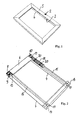
- Figure 1 illustrates a frame 2, in which a roller blind device according to the invention is integrated.
- the frame 2 consists of a lower frame part 4 and an upper one Frame part 5. Also recognizable is a guide slot 3.
- the frame 2 is made preferably made of sheet metal or plastic profiles, which are shaped so that they after the Assembly enclosing the mechanics detailed below.
- the guide slot 3 At the Inside the frame 2 remains the guide slot 3, in which the cloth and the Move tension rod guided.
- FIG 2 shows the arrangement shown in Figure 1 without the upper frame part 5, whereby a Part of the mechanics becomes visible.
- the darkening cloth 6 is on a Cloth shaft wound and deflected once over a deflection shaft 8. With the cloth wave are a cable spool 9 and a bevel gear 10 rotatably connected.
- the cloth shaft is in Clip holder 11, which simultaneously hold the frame parts 4 and 5, clipped.
- With the Cloth end is connected to a pull rod 12.
- the details of the tension bar 12, the two-part is formed, are best seen in Figure 5.
- the tension rod 12 consists of two parallel bars wrapped by the cloth 6 and between which the cloth 6 is trapped.
- the tension rod 12 is hollow inside and can thus the pull rope and Take up springs, which will be discussed below.
- Seilumlenlcmaschine 13 In both ends of the Tension rod are Seilumlenlcmaschine 13 inserted, which is also best seen in Figure 5 is.
- the Seilumlenlaeile 13 are also shown in Figure 10 in detail. From this Representation can be seen that the Seilumlenkmaschine 13 not only the introduction of the pull rope serve in the tie rod, but also the connection of the two separate and parallel Guided rods of the pull rod by joint insertion of both Seilumlenkmaschine 13 in the respective, juxtaposed ends of the two parts of the tension rod 12.
- the tie rod 12 and the wrapped cloth 6 is a U-shaped Slipped profile, which can be seen in Figure 6. This stabilizes the structure and prevents it the Switzerlandstabhow can tip over at low spring tension.
- frame connecting parts 14 provided at the corners of the frame 2, which at the same time as Deflection parts serve for the traction cables 15 and 16, which are deflected around the coils 17 so be that they are guided by the tie rod 12 to the cable coil 9.
- a Electric gear motor 18 which rotates the roller tube by means of a bevel gear 19.
- the Motor 18 is by means of the motor mount 20, which is shown in detail in Figure 11, with connected to the lower frame part 4.
- the fabric shaft 7 itself is best seen in Figure 5, which is a representation according to Figure 4, but without the cloth to be wound 6 shows. Incidentally, the description of the Figure 5 to the description of Figures 2-4 reference. Especially shown in Figures 4 and 5 are also the clip holder 11 for receiving the Cloth shaft 7.
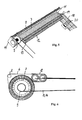
- Figure 6 shows a cross-sectional view of Figure 4, wherein both the leadership of the cloth 6 and the guide of the pull cable 15 and 16 are shown. The location of the cross section is not chosen in a particular place for the sake of clarity.
- Figure 6 is to see that the cloth 6 is wound on the fabric shaft 7 and a Guide shaft 8 down (in Figure 6 to the right) is deflected.
- Figure 6 shows the Cable reel 9, on which the pull cable 15, 16 is wound up.
- Figure 6 shows the Tension rod 12, consisting of two cylindrical tubes, which are parallel to each other, and around which the cloth 6 is wound in the form of an "8" and between which it is clamped is.
- the cohesion of the two components (cylindrical sleeves) of the tension rod 9 is by the components already described and shown in Figure 10 for cable deflection or tie rod connection causes. As previously described, is about the cylindrical Components of the tie rod and the wrapped cloth a U-shaped profile inverted and thus preventing a tipping over of the tension rod.
- FIG. 6 shows that the effect the cloth deflection shaft 8 is that the cloth 6 is always on the same plane.
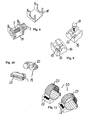
- FIG. 8 shows the frame connecting part 11, which both the illustrated fabric shaft 7 and the deflection shaft 8, not shown, receives in claws provided for this purpose by clipping.
- Figure 8 shows the frame connecting part 11 once without and once with clipped Cloth shaft 7 and cable coil 9.
- Figure 9 shows the further frame-connecting part 14 also in two representations with the coils 17, wherein the coil 17 in a representation half pulled out. The coils 17 serve as described the rope deflection.
- the frame connecting parts 14 for mounting in the lower left and the lower right Corner of the frame are mirror-symmetrical and each have two holes 23, in which the coils 17 are inserted. By repositioning the coil 17 in the one or other hole the blind device can be created with left or right drive.
- FIG. 11 shows the holder 20 for the motor 18 in detail.
- This holder 20 consists of a "shoe" which is connected to the lower frame part 4 and in which the motor 18th can be inserted accurately.
- About the engine body of the clamping bracket 27 is placed and clamped and locked by means of screws 28. This allows the motor 18 by loosening the screws 28 as required shifted on its longitudinal side and the bevel gears can be exactly engaged with each other.
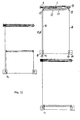
- Partial figure (a) shows the condition at full rolled-up cloth 6, part figure (b) with half rolled up or half unrolled cloth 6 and Part figure (c) shows the state with completely unrolled cloth 6.
- Partial figure (a) shows the condition at full rolled-up cloth 6, part figure (b) with half rolled up or half unrolled cloth 6 and Part figure (c) shows the state with completely unrolled cloth 6.
- the same Representation applies to the other embodiments described below become.
- the operation is without the cloth. 6 and the drop bar 12.
- the drop rod 12 is located between each shown rope deflections 13.
- the roller blind When the roller blind now opens or closes, it opens up a middle state, as indicated in sub-figure (b), permanently a different one Quantity cloth 6 or rope 15, 16 wound up or down, since with increasing settlement of the Tuches (from (a) to (c)), the outer diameter of the fabric shaft 7 decreases during at the same time the outer diameter of the cable shaft 9 through the wound ropes 15 and 16 increases.
- part figure (b) it is shown that the outer diameter of the fabric shaft 7 is the same the outer diameter of the cable shaft 9 is.
- the springs 21st and 22 maximally stretched, since here the maximum free length of the ropes 15 and 16 is present.
- the springs 21 and 22 by the increasing outer diameter of the cable spool 9 and the further decreasing Outer diameter of the fabric shaft 7 in turn compressed.
- FIG. 12 shows in its subfigures (a), (b) and (c) a similar embodiment as FIG 7, but instead of compression springs tension springs are used.
- tension springs are used.
- connections between the Extension springs 21 and 22 and the cable guide 13 are provided to the springs 21 and 22 hold.
- the springs in the Middle position (b) to minimum length while in the end positions (a) and (c) on maximum length are.
- thermo blind device corresponding profiled frame, as shown in Figure 1, as a substitute for the use so-called glazing beads.
- the glazing beads of a window are those strips that hold the glass in the frame. These glazing beads can removed and replaced by a roller blind device or its frame according to the invention be achieved, which one low installation depth and height and also a maximum incidence of light.
- the glass strip can be replaced by an angle profile that is shaped so that it picks up the standard frame of the roller blind device described by clipping.
- the device Since the device has a self-supporting frame, it can also as independent roller blind, by clamping or screwing, be mounted in the window rebate.
Landscapes
- Engineering & Computer Science (AREA)
- Structural Engineering (AREA)
- Architecture (AREA)
- Civil Engineering (AREA)
- Operating, Guiding And Securing Of Roll- Type Closing Members (AREA)
- Blinds (AREA)
- Wing Frames And Configurations (AREA)
- Support Devices For Sliding Doors (AREA)
- Massaging Devices (AREA)
- Seal Device For Vehicle (AREA)
Description
- Figur 1:
- Eine Rollovorrichtung innerhalb eines Trägerrahmens;
- Figur 2:
- Einen teilweisen Schnitt der in Figur 1 dargestellten Rollovonichtung innerhalb des Trägerrahmens;
- Figur 3:
- Eine Darstellung gemäß Figur 2, jedoch ohne Rahmenelemente;
- Figur 4:
- Eine vergrößerte Darstellung des Wickelbereiches der in Figur 3 dargestellten Rollovorrichtung;
- Figur 5:
- Eine Darstellung gemäß Figur 4, jedoch ohne das zu wickelnde Tuch;
- Figur 6:
- Eine Querschnittdarstellung durch die Anordnung gemäß Figur 4, welches sowohl die Führung des Tuches 6 als auch die des Zugseils 15, 16 zeigt;
- Figur 7:
- Eine schematische Frontalansicht der Rollovorrichtung in den drei
Wickelzuständen
- (a) aufgerolltes Tuch
- (b) halbaufgerolltes Tuch
- (c) abgerolltes Tuch;
- Figur 8:
- Ein rahmenverbindendes Teil für den Rahmen gemäß Figur 1 bis 3;
- Figur 9:
- Ein weiteres rahmenverbindendes Teil für den Rahmen gemäß Figuren 1 bis 3;
- Figur 10:
- Das Verbindungselement der Fallstabprofile, welches gleichzeitig als Seilumlenkung dient;
- Figur 11:
- Die Halterung für den Motor der Rollovorrichtung;
- Figur 12:
- Eine Variante des Ausführungsbeispiels gemäß Figur 7, wobei anstelle von Druckfedern Zugfedern verwendet werden;
Claims (5)
- Rollovorrichtung mit einem auf eine drehantreibbare, an einem Rahmen (4, 5) gelagerte Tuchwelle (7) aufwickelbaren Tuch und einem an der freien Kante des Tuches angeordneten Zugstab (12), auf den in Abzugsrichtung des Tuches eine Kraft wirkt, wobei koaxial und in Verlängerung der Tuchwelle (7) eine Seilspule (9) drehfest mit der Tuchwelle (7) verbunden ist und die freien Enden jedes darauf aufwickelbaren Seils über mindestens eine Seilumlenkung (17) mit dem hohl ausgebildeten Zugstab (12) verbunden ist, wodurch sich beim Abziehen des Tuches von der Tuchwelle (7) das Seil auf der Seilspule (9) aufwickelt und umgekehrt, und im Verlauf des Seils sowie innerhalb des Zugstabs (12) mindestens eine Federanordnung zur Anpassung der Länge des Seils an den variierenden Wickelzustand von Tuchwelle (7) und Seilspule (9) vorgesehen ist, dadurch gekennzeichnet, dass auf der genau einen Seilspule (9) zwei Seile (15, 16) aufwickelbar sind, wobei das freie Ende des einen Seils dem einen Ende des Zugstabs (12) und das freie Ende des anderen Seils dem anderen Ende des Zugstabs (12) zugeführt ist und die oder jede Federanordnung als Schraubenfeder (21, 22) ausgebildet ist, für jedes Seil (15, 16) eine eigene Schraubenfeder (21, 22) vorgesehen ist, die Schraubenfedern sich an Seilumlenkungen (13) an den inneren, gegenüberliegenden Enden des Zugstabs (12) abstützen, und der Zugstab (12) zwei parallel zueinander verlaufende zylindrische Stabteile aufweist, wobei jedes Stabteil eine der beiden Schraubenfedern (21, 22) aufnimmt.
- Rollovorrichtung nach Anspruch 1, dadurch gekennzeichnet, dass beide Seile seitlich in den Zugstab (12) hineingeführt sind, innerhalb des Zugstabes (12) durch beide darin angeordneten, auf Druck vorgespannten Schraubenfedern (21, 22) geführt sind und an ihren freien Enden Verdickungen (23) aufweisen, deren Ausdehnung mindestens dem Durchmesser der Schraubenfedern (21, 22) entspricht oder mit dieser verbunden sind.
- Rollovorrichtung nach Anspruch 1 , dadurch gekennzeichnet, dass beide Seile (15, 16) seitlich in den Zugstab (12) hineingeführt sind und innerhalb des Zugstabes (12) jeweils am Ende einer auf Zug vorgespannten und nur einem Seil (15 oder 16) zugeordneten Schraubenfeder befestigt sind, deren anderes Ende an dem Zugstab (12) befestigt ist.
- Isolierglasscheibe mit zwei Scheiben und einem dazwischen befindlichen Innenraum, dadurch gekennzeichnet, dass in dem Innenraum eine Rollovorrichtung nach einem der voranstehenden Ansprüche angeordnet ist.
- Fenster mit einem Rahmen und mindestens einer Scheibe, welche mit Glasleisten in dem Rahmen fixiert ist, und mit einer Rollovorrichtung nach einem der Ansprüche 1 bis 3 dadurch gekennzeichnet, dass anstelle mindestens einer Glasleiste das Gehäuse der Rollovorrichtung oder ein diesem Gehäuse zugeordnetes Winkelprofil die Scheibe fixiert.
Applications Claiming Priority (3)
| Application Number | Priority Date | Filing Date | Title |
|---|---|---|---|
| DE10232536 | 2002-07-18 | ||
| DE10232536A DE10232536B4 (de) | 2002-07-18 | 2002-07-18 | Rollovorrichtung |
| PCT/EP2003/005383 WO2004009947A1 (de) | 2002-07-18 | 2003-05-23 | Rollovorrichtung |
Publications (2)
| Publication Number | Publication Date |
|---|---|
| EP1525368A1 EP1525368A1 (de) | 2005-04-27 |
| EP1525368B1 true EP1525368B1 (de) | 2005-11-02 |
Family
ID=30128146
Family Applications (1)
| Application Number | Title | Priority Date | Filing Date |
|---|---|---|---|
| EP03735439A Expired - Lifetime EP1525368B1 (de) | 2002-07-18 | 2003-05-23 | Rollovorrichtung |
Country Status (8)
| Country | Link |
|---|---|
| US (1) | US7059376B2 (de) |
| EP (1) | EP1525368B1 (de) |
| JP (1) | JP2005533207A (de) |
| AT (1) | ATE308663T1 (de) |
| AU (1) | AU2003237659A1 (de) |
| DE (2) | DE10232536B4 (de) |
| ES (1) | ES2250895T3 (de) |
| WO (1) | WO2004009947A1 (de) |
Families Citing this family (30)
| Publication number | Priority date | Publication date | Assignee | Title |
|---|---|---|---|---|
| NO320850B1 (no) * | 2004-01-09 | 2006-02-06 | Hagen Persiennesystemer As | Strammeanordning for motorisert rullegardin innsatt mellom isolerglass samt anvendelse derav. |
| CN101336330B (zh) * | 2005-12-12 | 2012-10-31 | 澳大利亚森特股份有限公司 | 横拉卷式纱网组件 |
| WO2007137338A1 (en) | 2006-05-26 | 2007-12-06 | Centor Australia Pty Ltd | A screen assembly for a window or door opening |
| US20090277593A1 (en) * | 2008-05-09 | 2009-11-12 | Stewart Grant W | Acoustic window shade |
| JP5028075B2 (ja) * | 2006-12-04 | 2012-09-19 | キヤノン株式会社 | 撮像装置及び撮像方法 |
| DE102007030357B4 (de) | 2007-06-29 | 2009-09-03 | Visio-Glas Gmbh Isolierglaswerk | Rollo mit Spannvorrichtung sowie Mehrscheiben-Isolierglaselement mit einem solchen Rollo |
| US8113264B2 (en) * | 2008-03-12 | 2012-02-14 | Lutron Electronics Co., Inc. | Tensioned roller shade system having a conical, grooved spool |
| US8056601B2 (en) * | 2008-03-12 | 2011-11-15 | Lutron Electronics Co., Inc. | Self-contained tensioned roller shade system |
| US8757239B2 (en) * | 2008-08-26 | 2014-06-24 | Hunter Douglas Inc. | Roll-up retractable covering for architectural openings |
| USD632118S1 (en) * | 2009-05-15 | 2011-02-08 | Designed Blinds Australia Pty Ltd | Overlapping roller blind system |
| US20120061036A1 (en) * | 2010-09-09 | 2012-03-15 | Agbegnenou Desire Agbozouhoue | Retractable window mat |
| JP5884281B2 (ja) * | 2010-11-05 | 2016-03-15 | アイシン精機株式会社 | 車両用サンシェード |
| JP5736249B2 (ja) * | 2011-06-24 | 2015-06-17 | 林口工業株式会社 | 一体型ロールスクリーンユニット |
| AT513942B1 (de) * | 2013-01-22 | 2017-11-15 | Htp High Tech Plastics Gmbh | Vorrichtung zur Abdeckung einer Sichtöffnung |
| AU350920S (en) | 2013-06-20 | 2013-09-20 | Centor Design Pty Ltd | Stile |
| AU350916S (en) | 2013-06-20 | 2013-09-20 | Centor Design Pty Ltd | Hinge |
| US9689201B2 (en) | 2013-06-28 | 2017-06-27 | Screenaway Pty Ltd | Screen system |
| USD833248S1 (en) | 2013-12-20 | 2018-11-13 | Centor Design Pty Ltd | Door handle |
| BE1023551B1 (nl) * | 2015-10-30 | 2017-05-02 | Renson Sunprotection Screens N.V. | Scherminrichting |
| USD839712S1 (en) | 2017-07-20 | 2019-02-05 | Centor Design Pty Ltd | Concealed hinge |
| USD839713S1 (en) | 2017-07-20 | 2019-02-05 | Centor Design Pty Ltd | Offset concealed hinge |
| US11377904B2 (en) | 2018-12-14 | 2022-07-05 | Crestron Electronics, Inc. | Roller shade for non-rectangular windows |
| US11053731B2 (en) | 2019-05-28 | 2021-07-06 | Crestron Electronics, Inc. | Skylight roller shade with a cable cone indexing mechanism |
| US11053732B2 (en) | 2019-05-28 | 2021-07-06 | Crestron Electronics, Inc. | Skylight roller shade alignment mechanism |
| JP2021031949A (ja) * | 2019-08-23 | 2021-03-01 | 株式会社Lixil | スクリーン装置 |
| CN111663888B (zh) * | 2020-06-12 | 2024-07-09 | 中铁四院集团广州设计院有限公司 | 卷帘式挡烟垂壁 |
| CN111577090A (zh) * | 2020-06-22 | 2020-08-25 | 苏州锦至华建筑材料科技有限公司 | 一种电控调解式中空百叶窗 |
| CN111706222B (zh) * | 2020-06-28 | 2021-03-12 | 浙江绿城建筑幕墙工程有限公司 | 一种钢化玻璃窗户 |
| AU2022337213B2 (en) | 2021-09-01 | 2023-11-09 | Ublockout Technologies Pty Ltd | Lockable corner bracket |
| CN113898283B (zh) * | 2021-10-21 | 2023-08-18 | 李新成 | 一种弧形门 |
Family Cites Families (17)
| Publication number | Priority date | Publication date | Assignee | Title |
|---|---|---|---|---|
| US1121898A (en) * | 1914-01-03 | 1914-12-22 | E T Burrowes Company | Window-screen. |
| US2958083A (en) * | 1955-09-19 | 1960-11-01 | Nemoede | Swimming pool safety device |
| DE3575763D1 (de) * | 1984-02-27 | 1990-03-08 | Kurt Kunz | Zum einbau in eine isolier-verglasung vorgesehene rolloeinrichtung und isolier-verglasung mit rolloeinrichtung. |
| GB2166480A (en) * | 1984-11-02 | 1986-05-08 | Guthrie Douglas Ltd | Roller apparatus |
| LU85947A1 (fr) * | 1985-06-13 | 1987-01-13 | Harol S A Nv | Dispositif de protection de constructions vitrees contre les rayonnements solaires |
| DE8703605U1 (de) * | 1987-03-11 | 1987-05-07 | Hüppe GmbH, 2900 Oldenburg | Rollo für Automobilfenster, insbesondere für PKW-Heckscheiben |
| DE3836595A1 (de) | 1988-03-26 | 1989-10-12 | Philipp Tussinger | Vorrichtung zum abdunkeln von fenstern |
| US5067184A (en) * | 1988-10-17 | 1991-11-26 | Last Harry J | Cover drum having tapered ends and automatic swimming pool cover |
| DE9001090U1 (de) | 1990-02-01 | 1991-05-23 | Tussinger, Philipp, 7505 Ettlingen | Fenster mit Vorrichtung zum Abdunkeln |
| DE4031031A1 (de) * | 1990-10-01 | 1992-04-02 | Inn Glasbau Gmbh | Isolierglasanordnung |
| US5287908A (en) * | 1991-12-19 | 1994-02-22 | Hunter Douglas Inc. | Window covering assembly |
| DE9215788U1 (de) * | 1992-11-20 | 1993-01-21 | Goldner, Horst H., 8061 Oberroth | Gegenzugrollo |
| DE4342977A1 (de) * | 1993-12-16 | 1995-06-22 | Hubert Muench | Vorrichtung zum Betätigen einer Lamellenjalousie |
| DE29514865U1 (de) * | 1995-09-15 | 1995-11-02 | Kunz, Kurt, Schlattingen | Behang zur Abdunkelung von Fensteröffnungen |
| EP0795674A3 (de) * | 1996-03-08 | 1998-09-23 | Hunter Douglas Industries B.V. | Lichtregulierende Abdeckung für Gebäudeöffnungen |
| DE19737632C2 (de) * | 1997-08-28 | 2000-04-20 | Horst H Goldner | Kombinierte Rollo- und Jalousieabdeckvorrichtung für eine Fensteröffnung |
| DE20021691U1 (de) * | 2000-01-20 | 2001-04-12 | Lutz, Franz, 86657 Bissingen | Isolierglasscheibe mit integrierter Rolloeinrichtung |
-
2002
- 2002-07-18 DE DE10232536A patent/DE10232536B4/de not_active Expired - Fee Related
-
2003
- 2003-05-23 WO PCT/EP2003/005383 patent/WO2004009947A1/de not_active Ceased
- 2003-05-23 EP EP03735439A patent/EP1525368B1/de not_active Expired - Lifetime
- 2003-05-23 JP JP2004522166A patent/JP2005533207A/ja active Pending
- 2003-05-23 AU AU2003237659A patent/AU2003237659A1/en not_active Abandoned
- 2003-05-23 DE DE50301578T patent/DE50301578D1/de not_active Expired - Lifetime
- 2003-05-23 AT AT03735439T patent/ATE308663T1/de not_active IP Right Cessation
- 2003-05-23 ES ES03735439T patent/ES2250895T3/es not_active Expired - Lifetime
-
2005
- 2005-01-14 US US11/036,597 patent/US7059376B2/en not_active Expired - Fee Related
Also Published As
| Publication number | Publication date |
|---|---|
| ATE308663T1 (de) | 2005-11-15 |
| JP2005533207A (ja) | 2005-11-04 |
| US7059376B2 (en) | 2006-06-13 |
| DE10232536A1 (de) | 2004-02-12 |
| US20050161175A1 (en) | 2005-07-28 |
| DE50301578D1 (de) | 2005-12-08 |
| ES2250895T3 (es) | 2006-04-16 |
| AU2003237659A1 (en) | 2004-02-09 |
| EP1525368A1 (de) | 2005-04-27 |
| WO2004009947A1 (de) | 2004-01-29 |
| DE10232536B4 (de) | 2004-09-30 |
Similar Documents
| Publication | Publication Date | Title |
|---|---|---|
| EP1525368B1 (de) | Rollovorrichtung | |
| EP1010559B1 (de) | Sonnenrollo für ein Kraftfahrzeugdach | |
| DE10124100C1 (de) | Rollovorrichtung für ein transparentes Dachelement | |
| DE102007054694A1 (de) | Rolloanordnung mit verminderter Reibung in den Antriebsgabeln | |
| DE202004014652U1 (de) | Fahrzeugtür mit einem Fensterheber | |
| DE19610268C2 (de) | Rolloeinrichtung für ein Isolierglaselement | |
| DE3245009A1 (de) | Rolltor | |
| EP1626152A1 (de) | Sonnenschutzrollo für Glasdächer | |
| DE3345503A1 (de) | Rollo fuer fahrzeugscheiben | |
| DE102008008941B4 (de) | Sonnenschutzanlage mit einem wickelbaren Behang | |
| DE102009045746A1 (de) | Rolloanordnung mit wengistens einer Wickelwelle und einem Vorhangelement sowie Glaseinheit und Verfahren zum Auf- und/oder Abwickeln eines Vorhangelements von einer Wickelwelle | |
| DE202009002343U1 (de) | Verdunklungs- oder Abschirmungsvorhang und Verdunklungs- oder Abschirmungsvorrichtung | |
| EP2009219B1 (de) | Rollo mit Spannvorrichtung sowie Mehrscheiben-Isolierglaselement mit einem solchen Rollo | |
| DE102013114674A1 (de) | Rollo | |
| DE10316785B4 (de) | Rollovorrichtung | |
| DE20210855U1 (de) | Rollovorrichtung | |
| DE3700745A1 (de) | Faltstore zum innenseitigen verschatten von insbesondere wintergaerten od. dergl. | |
| DE202006009738U1 (de) | Führungsanordnung für einen Querriegel eines Abschattungsmittels | |
| EP0383067B1 (de) | Rolladen für Wand- oder Dachöffungen, insbesondere mit einem schwenkbaren Dachfenster | |
| EP0529591B1 (de) | Rolloanordnung, vorzugsweise für Kraftfahrzeugheckscheiben | |
| DE4327230C1 (de) | Rolladen für Dachfenster | |
| DE3644557A1 (de) | Rollovorrichtung fuer die aussenseite eines fensters | |
| DE29723473U1 (de) | Schutzvorrichtung zum Abdecken eines Fensters mittels eines biegsamen Flachmaterials | |
| DE10063454B4 (de) | Vorrichtung zum Verschließen und/oder Beschatten eines Öffnungsquerschnitts bzw. einer Fläche | |
| DE202004019844U1 (de) | Fensterrollo für ein Fahrzeugfenster |
Legal Events
| Date | Code | Title | Description |
|---|---|---|---|
| PUAI | Public reference made under article 153(3) epc to a published international application that has entered the european phase |
Free format text: ORIGINAL CODE: 0009012 |
|
| 17P | Request for examination filed |
Effective date: 20050218 |
|
| AK | Designated contracting states |
Kind code of ref document: A1 Designated state(s): AT BE BG CH CY CZ DE DK EE ES FI FR GB GR HU IE IT LI LU MC NL PT RO SE SI SK TR |
|
| AX | Request for extension of the european patent |
Extension state: AL LT LV MK |
|
| GRAP | Despatch of communication of intention to grant a patent |
Free format text: ORIGINAL CODE: EPIDOSNIGR1 |
|
| GRAS | Grant fee paid |
Free format text: ORIGINAL CODE: EPIDOSNIGR3 |
|
| GRAA | (expected) grant |
Free format text: ORIGINAL CODE: 0009210 |
|
| AK | Designated contracting states |
Kind code of ref document: B1 Designated state(s): AT BE BG CH CY CZ DE DK EE ES FI FR GB GR HU IE IT LI LU MC NL PT RO SE SI SK TR |
|
| DAX | Request for extension of the european patent (deleted) | ||
| PG25 | Lapsed in a contracting state [announced via postgrant information from national office to epo] |
Ref country code: FI Free format text: LAPSE BECAUSE OF FAILURE TO SUBMIT A TRANSLATION OF THE DESCRIPTION OR TO PAY THE FEE WITHIN THE PRESCRIBED TIME-LIMIT Effective date: 20051102 Ref country code: NL Free format text: LAPSE BECAUSE OF FAILURE TO SUBMIT A TRANSLATION OF THE DESCRIPTION OR TO PAY THE FEE WITHIN THE PRESCRIBED TIME-LIMIT Effective date: 20051102 Ref country code: CZ Free format text: LAPSE BECAUSE OF FAILURE TO SUBMIT A TRANSLATION OF THE DESCRIPTION OR TO PAY THE FEE WITHIN THE PRESCRIBED TIME-LIMIT Effective date: 20051102 Ref country code: SI Free format text: LAPSE BECAUSE OF FAILURE TO SUBMIT A TRANSLATION OF THE DESCRIPTION OR TO PAY THE FEE WITHIN THE PRESCRIBED TIME-LIMIT Effective date: 20051102 Ref country code: RO Free format text: LAPSE BECAUSE OF FAILURE TO SUBMIT A TRANSLATION OF THE DESCRIPTION OR TO PAY THE FEE WITHIN THE PRESCRIBED TIME-LIMIT Effective date: 20051102 Ref country code: IE Free format text: LAPSE BECAUSE OF FAILURE TO SUBMIT A TRANSLATION OF THE DESCRIPTION OR TO PAY THE FEE WITHIN THE PRESCRIBED TIME-LIMIT Effective date: 20051102 Ref country code: SK Free format text: LAPSE BECAUSE OF FAILURE TO SUBMIT A TRANSLATION OF THE DESCRIPTION OR TO PAY THE FEE WITHIN THE PRESCRIBED TIME-LIMIT Effective date: 20051102 Ref country code: GB Free format text: LAPSE BECAUSE OF FAILURE TO SUBMIT A TRANSLATION OF THE DESCRIPTION OR TO PAY THE FEE WITHIN THE PRESCRIBED TIME-LIMIT Effective date: 20051102 |
|
| REG | Reference to a national code |
Ref country code: GB Ref legal event code: FG4D Free format text: NOT ENGLISH |
|
| REG | Reference to a national code |
Ref country code: CH Ref legal event code: EP |
|
| REF | Corresponds to: |
Ref document number: 50301578 Country of ref document: DE Date of ref document: 20051208 Kind code of ref document: P |
|
| PG25 | Lapsed in a contracting state [announced via postgrant information from national office to epo] |
Ref country code: GR Free format text: LAPSE BECAUSE OF FAILURE TO SUBMIT A TRANSLATION OF THE DESCRIPTION OR TO PAY THE FEE WITHIN THE PRESCRIBED TIME-LIMIT Effective date: 20060202 Ref country code: SE Free format text: LAPSE BECAUSE OF FAILURE TO SUBMIT A TRANSLATION OF THE DESCRIPTION OR TO PAY THE FEE WITHIN THE PRESCRIBED TIME-LIMIT Effective date: 20060202 Ref country code: BG Free format text: LAPSE BECAUSE OF FAILURE TO SUBMIT A TRANSLATION OF THE DESCRIPTION OR TO PAY THE FEE WITHIN THE PRESCRIBED TIME-LIMIT Effective date: 20060202 Ref country code: DK Free format text: LAPSE BECAUSE OF FAILURE TO SUBMIT A TRANSLATION OF THE DESCRIPTION OR TO PAY THE FEE WITHIN THE PRESCRIBED TIME-LIMIT Effective date: 20060202 |
|
| PGFP | Annual fee paid to national office [announced via postgrant information from national office to epo] |
Ref country code: FR Payment date: 20060222 Year of fee payment: 4 |
|
| PG25 | Lapsed in a contracting state [announced via postgrant information from national office to epo] |
Ref country code: PT Free format text: LAPSE BECAUSE OF FAILURE TO SUBMIT A TRANSLATION OF THE DESCRIPTION OR TO PAY THE FEE WITHIN THE PRESCRIBED TIME-LIMIT Effective date: 20060403 |
|
| REG | Reference to a national code |
Ref country code: ES Ref legal event code: FG2A Ref document number: 2250895 Country of ref document: ES Kind code of ref document: T3 |
|
| NLV1 | Nl: lapsed or annulled due to failure to fulfill the requirements of art. 29p and 29m of the patents act | ||
| PGFP | Annual fee paid to national office [announced via postgrant information from national office to epo] |
Ref country code: TR Payment date: 20060501 Year of fee payment: 4 |
|
| PG25 | Lapsed in a contracting state [announced via postgrant information from national office to epo] |
Ref country code: HU Free format text: LAPSE BECAUSE OF FAILURE TO SUBMIT A TRANSLATION OF THE DESCRIPTION OR TO PAY THE FEE WITHIN THE PRESCRIBED TIME-LIMIT Effective date: 20060503 |
|
| GBV | Gb: ep patent (uk) treated as always having been void in accordance with gb section 77(7)/1977 [no translation filed] |
Effective date: 20051102 |
|
| PG25 | Lapsed in a contracting state [announced via postgrant information from national office to epo] |
Ref country code: MC Free format text: LAPSE BECAUSE OF NON-PAYMENT OF DUE FEES Effective date: 20060531 Ref country code: BE Free format text: LAPSE BECAUSE OF NON-PAYMENT OF DUE FEES Effective date: 20060531 |
|
| PGFP | Annual fee paid to national office [announced via postgrant information from national office to epo] |
Ref country code: IT Payment date: 20060531 Year of fee payment: 4 |
|
| PGFP | Annual fee paid to national office [announced via postgrant information from national office to epo] |
Ref country code: ES Payment date: 20060623 Year of fee payment: 4 |
|
| REG | Reference to a national code |
Ref country code: IE Ref legal event code: FD4D |
|
| ET | Fr: translation filed | ||
| PLBE | No opposition filed within time limit |
Free format text: ORIGINAL CODE: 0009261 |
|
| STAA | Information on the status of an ep patent application or granted ep patent |
Free format text: STATUS: NO OPPOSITION FILED WITHIN TIME LIMIT |
|
| 26N | No opposition filed |
Effective date: 20060803 |
|
| BERE | Be: lapsed |
Owner name: TUSSINGER, PHILIPP Effective date: 20060531 |
|
| REG | Reference to a national code |
Ref country code: CH Ref legal event code: PL |
|
| PG25 | Lapsed in a contracting state [announced via postgrant information from national office to epo] |
Ref country code: LI Free format text: LAPSE BECAUSE OF NON-PAYMENT OF DUE FEES Effective date: 20070531 Ref country code: CH Free format text: LAPSE BECAUSE OF NON-PAYMENT OF DUE FEES Effective date: 20070531 |
|
| REG | Reference to a national code |
Ref country code: FR Ref legal event code: ST Effective date: 20080131 |
|
| PG25 | Lapsed in a contracting state [announced via postgrant information from national office to epo] |
Ref country code: EE Free format text: LAPSE BECAUSE OF FAILURE TO SUBMIT A TRANSLATION OF THE DESCRIPTION OR TO PAY THE FEE WITHIN THE PRESCRIBED TIME-LIMIT Effective date: 20051102 |
|
| PG25 | Lapsed in a contracting state [announced via postgrant information from national office to epo] |
Ref country code: LU Free format text: LAPSE BECAUSE OF NON-PAYMENT OF DUE FEES Effective date: 20060523 Ref country code: FR Free format text: LAPSE BECAUSE OF NON-PAYMENT OF DUE FEES Effective date: 20070531 |
|
| REG | Reference to a national code |
Ref country code: ES Ref legal event code: FD2A Effective date: 20070524 |
|
| PGFP | Annual fee paid to national office [announced via postgrant information from national office to epo] |
Ref country code: AT Payment date: 20080513 Year of fee payment: 6 |
|
| PG25 | Lapsed in a contracting state [announced via postgrant information from national office to epo] |
Ref country code: ES Free format text: LAPSE BECAUSE OF NON-PAYMENT OF DUE FEES Effective date: 20070524 |
|
| PG25 | Lapsed in a contracting state [announced via postgrant information from national office to epo] |
Ref country code: CY Free format text: LAPSE BECAUSE OF FAILURE TO SUBMIT A TRANSLATION OF THE DESCRIPTION OR TO PAY THE FEE WITHIN THE PRESCRIBED TIME-LIMIT Effective date: 20051102 |
|
| PG25 | Lapsed in a contracting state [announced via postgrant information from national office to epo] |
Ref country code: IT Free format text: LAPSE BECAUSE OF NON-PAYMENT OF DUE FEES Effective date: 20070523 Ref country code: TR Free format text: LAPSE BECAUSE OF FAILURE TO SUBMIT A TRANSLATION OF THE DESCRIPTION OR TO PAY THE FEE WITHIN THE PRESCRIBED TIME-LIMIT Effective date: 20051102 |
|
| PG25 | Lapsed in a contracting state [announced via postgrant information from national office to epo] |
Ref country code: AT Free format text: LAPSE BECAUSE OF NON-PAYMENT OF DUE FEES Effective date: 20090523 |
|
| PGFP | Annual fee paid to national office [announced via postgrant information from national office to epo] |
Ref country code: DE Payment date: 20100706 Year of fee payment: 8 |
|
| REG | Reference to a national code |
Ref country code: DE Ref legal event code: R119 Ref document number: 50301578 Country of ref document: DE Effective date: 20111201 |
|
| PG25 | Lapsed in a contracting state [announced via postgrant information from national office to epo] |
Ref country code: DE Free format text: LAPSE BECAUSE OF NON-PAYMENT OF DUE FEES Effective date: 20111201 |