EP1522261B1 - Röntgenabbildungsgerät und Verfahren zur Bewegung eines Röntgenstrahlungsdetektors - Google Patents
Röntgenabbildungsgerät und Verfahren zur Bewegung eines Röntgenstrahlungsdetektors Download PDFInfo
- Publication number
- EP1522261B1 EP1522261B1 EP04256243A EP04256243A EP1522261B1 EP 1522261 B1 EP1522261 B1 EP 1522261B1 EP 04256243 A EP04256243 A EP 04256243A EP 04256243 A EP04256243 A EP 04256243A EP 1522261 B1 EP1522261 B1 EP 1522261B1
- Authority
- EP
- European Patent Office
- Prior art keywords
- ray
- detecting unit
- capacitance
- distance
- imaging apparatus
- Prior art date
- Legal status (The legal status is an assumption and is not a legal conclusion. Google has not performed a legal analysis and makes no representation as to the accuracy of the status listed.)
- Expired - Lifetime
Links
Images


Classifications
-
- G—PHYSICS
- G01—MEASURING; TESTING
- G01B—MEASURING LENGTH, THICKNESS OR SIMILAR LINEAR DIMENSIONS; MEASURING ANGLES; MEASURING AREAS; MEASURING IRREGULARITIES OF SURFACES OR CONTOURS
- G01B7/00—Measuring arrangements characterised by the use of electric or magnetic techniques
- G01B7/02—Measuring arrangements characterised by the use of electric or magnetic techniques for measuring length, width or thickness
- G01B7/023—Measuring arrangements characterised by the use of electric or magnetic techniques for measuring length, width or thickness for measuring distance between sensor and object
-
- A—HUMAN NECESSITIES
- A61—MEDICAL OR VETERINARY SCIENCE; HYGIENE
- A61B—DIAGNOSIS; SURGERY; IDENTIFICATION
- A61B6/00—Apparatus or devices for radiation diagnosis; Apparatus or devices for radiation diagnosis combined with radiation therapy equipment
- A61B6/10—Safety means specially adapted therefor
- A61B6/102—Protection against mechanical damage, e.g. anti-collision devices
Definitions
- the present invention relates generally to an X-ray imaging apparatus and a method for moving X-ray detector.
- an angio X-ray imaging apparatus includes an X-ray generating part, an X-ray detecting part, a supporting part which supports the X-ray generating part and the X-ray detecting part, a bed and a processor, for example.
- the supporting part is a C-arm or an ⁇ -arm, for example, and the supporting part moves such that images of a patient are obtained from several angles or positions.
- an X-ray film or an I.I. (Image Intensifier) is used, for example.
- an X-ray tube of the X-ray generating part irradiates an X-ray to the patient, and the I.I. transfers the X-ray penetrated through the patient into an optical image.
- the optical image is changed to electric signals by an X-ray TV camera.
- the electric signals are converted by A/D converter and are displayed on a monitor as an X-ray image.
- A/D converter A/D converter
- digital signals are obtained, several image processes can be performed.
- a X-ray flat panel detector (referred to as a flat panel detector below) which has detection elements arranged in two dimension is developed.
- an imaging part including the X-ray generating part and the X-ray detecting part speedily moves in a wide range in order to move the C-arm according to a flow of a contrast agent in a blood vessel.
- the flat panel detector in order to obtain clear image data, it is required to arrange the flat panel detector in a predetermined position close to a surface of a body of the patient surface, and when the flat panel detector contacts the body of the patient, a movement of the X-ray detecting part stops by using a contact type sensor as one method.
- the capacitance sensor is attached around the flat panel detector of the X-ray detecting part. Using information of the capacitance which changes according to a position of the patient, a distance of the patient's body surface and the flat panel detector is measured. Based on information of the measured distance, speed of the movement of the X-ray detecting part is slowed down gradually, and the X-ray detecting part stops at a predetermined position near the patient. In this method, it is possible to move the X-ray detecting part at high speed to a position close to the patient's body surface, and efficiency for diagnosis improves. And it is possible to obtain an image even if the flow of the blood is fast.
- the X-ray detecting part does not stop at a desired position.
- JP2001 241910A discloses X-ray imaging using a capacitance sensing unit for determining the distance between the image and the object.
- the invention is an apparatus and a method as defined in claims 1 and 12.
- the present invention can ameliorate at least one problem described above.
- a capacitance sensor is sheet shaped, and the capacitance sensor covers an X-ray detection plane of the flat panel detector.
- a predetermined correction value corresponding to the patient's shape, age, sex and degree of obesity is applied to the value of the capacitance which is previously measured, and the presumption of the distance is performed based on the corrected value of the capacitance.
- FIG. 1 shows a block diagram of the X-ray imaging apparatus.
- the X-ray imaging apparatus 100 shown in FIG. 1 includes an X-ray generating part 1 which irradiates an X-ray to a patient 150, a high voltage generating part 4 which generates a high voltage supplied to the X-ray generating part 1, an X-ray detecting part 2 which detects the X-ray passed through the patient 150, a C-arm 5 which supports the X-ray generating part 1 and the X-ray detecting part 2, and a mechanical control part 3 which controls rotation of the C-arm 5 and movement of a bed plate 17 which the patient 150 is put on.
- the X-ray imaging apparatus 100 includes an image process memory part 7 which stores X-ray image data and performs several image processes to the X-ray image data, a display part 8 which displays the X-ray image data stored in the image process memory part 7, an operation part 9 by which an operator inputs patient information and several instructions or sets an imaging condition, a distance detection part 6 which detects the distance between the patient 150 and the X-ray generating part 1, and a system controller 10 which controls each part.
- the X-ray generating part 1 includes an X-ray tube 15 irradiated to the patient 150, and an X-ray limiting device 16 which forms a cone-shaped X-ray from the X-ray generated by the X-ray tube 15.
- the X-ray tube 15 is a vacuum tube which generates the X-ray.
- the X-ray is generated when an electron emitted from a filament is accelerated and collision between the accelerated electron and a tungsten anode occurs.
- the X-ray limiting device 16 is positioned between the X-ray tube 15 and the patient 150, and limits the X-ray irradiated from the X-ray tube 15 to a size of a predetermined field of view.
- the X-ray detecting part 2 includes a flat panel detector 21 where the X-ray passed through the patient 150 is transferred to an electric charge and the electric charge is accumulated, a gate driver 22 which reads out the accumulated electric charge as an X-ray signal, a projection data creating part 13 which creates X-ray projection data based on the electric charge, and a sensor part 26 which measures the distance between the patient 150 and the X-ray detecting part 2.
- a direct conversion type X-ray detector which directly converts the X-ray into the electric charge, or an indirect conversion type X-ray detector which converts the X-ray into the optical signal and then converts the optical signal into the electric charge, may be applied.
- the direct conversion type X-ray detector is explained, however the indirect conversion type X-ray detector may be used.
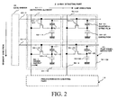
- the flat panel detector 21 includes a plurality of detection elements 51 which are arranged in two dimensions in a segment direction and a line direction.
- Each detection element 51 includes a photoelectric film 52 which generates the electric charge according to the incident X-ray, a charge accumulating capacitor 53 which accumulates the electric charge generated in the photoelectric film 52, and a TFT (Thin Film Transistor) 54 which reads out the accumulated electric charge by a predetermined period.
- TFT Thin Film Transistor
- First terminals of photoelectric films 52-11, 52-12, 52-21 and 52-22 in FIG.2 are connected to first terminals of the capacitors 53-11, 53-12, 53-21 and 53-22. Connection points between the first terminals of the photoelectric films and the first terminals of the capacitors are connected to source terminals of the TFT 54-11, 54-12, 54-21 and 54-22. Second terminals of the photoelectric films 52-11, 52-12, 52-21 and 52-22 are connected to a bias power supply. Second terminals of the capacitors 53-11, 53-12, 53-21 and 53-22 are grounded. Gate terminals of the TFT 54-11 TFT 54-21 arranged in the line direction are commonly connected to an output terminal 22-1 of the gate driver 22, and gate terminals of the TFT 54-12 TFT 54-22 are commonly connected to an output terminal 22-2 of the gate driver 22.
- drain terminals of the TFT 54-11 and 54-12 arranged in the segment direction are commonly connected to a signal output line 59-1
- drain terminals of the TFT 54-21 and 54-22 are commonly connected to a signal output line 59-2.
- the signal output lines 59-1 and 59-2 are connected to the projection data creating part 13.
- the gate driver 22 supplies a driving pulse to the gate terminal of the TFT54.
- the projection data creating part 13 includes an electric charge / voltage converter 23 which converts the electric charge read from the flat panel detector 21 into voltage, an A/D converter 24 which changes the output of the electric charge / voltage converter 23 into a digital signal, and a parallel serial converter 25 which changes the X-ray projection data which is read in parallel by each line into a time series signal.
- the sensor part 26 of the X-ray detecting part 2 is explained in a description about the distance detection part 6 below.
- the mechanical control part 3 includes a bed plate moving mechanism 32 which moves the bed plate 17 where the patient 150 is placed on in a body axis direction (direction perpendicular to FIG. 1 ) and in the right and left direction, an imaging part moving mechanism 31 which rotates the C arm 5 having the X-ray generating part 1 and the X-ray detecting part 2 around the patient 150 and which moves the X-ray detecting part 2 to the patient 150, and a mechanism controller 33 which controls the rotation and the movement.
- a bed plate moving mechanism 32 which moves the bed plate 17 where the patient 150 is placed on in a body axis direction (direction perpendicular to FIG. 1 ) and in the right and left direction
- an imaging part moving mechanism 31 which rotates the C arm 5 having the X-ray generating part 1 and the X-ray detecting part 2 around the patient 150 and which moves the X-ray detecting part 2 to the patient 150
- a mechanism controller 33 which controls the rotation and the movement.
- the mechanism controller 33 controls the imaging part moving mechanism 31 to set up a direction, amount and speed of the rotation of the C arm 5, or a direction, amount and speed of the rotation/movement of the X-ray detecting part 2.
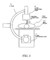
- FIG.3 the X-ray detecting part 2 and the X-ray generating part 1 which are set up to the patient 150 are shown.
- the mechanism controller 33 drives the imaging part moving mechanism 31 to move the X-ray detecting part 2, and a desired distance LD between the flat panel detector 21 which is attached in front of the X-ray detecting part 2 and the body surface of the patient 150 is set.
- the high-voltage generating part 4 includes a high-voltage generator 42 which generates the high voltage between the filament and the anode to accelerate the electron generated in the filament of the X-ray tube 15, and a high-voltage controller 41 which sets up an X-ray irradiation condition, such as tube current, a tube voltage and an irradiation time, according to an instruction signal from the systems controller 10.
- a high-voltage generator 42 which generates the high voltage between the filament and the anode to accelerate the electron generated in the filament of the X-ray tube 15, and a high-voltage controller 41 which sets up an X-ray irradiation condition, such as tube current, a tube voltage and an irradiation time, according to an instruction signal from the systems controller 10.
- the sensor part 26 of the X-ray detecting part 2 and the distance detection part 6 is explained with reference to FIG. 4 .
- the sensor part 26 is positioned near the flat panel detector 21 in the X-ray detecting part 2 of FIG. 1 .
- the sensor part 26 includes a capacitance sensor 261 which detects the capacitance in front of the flat panel detector 21, a contact sensor 262 which is positioned on a surface of the capacitance sensor 261, and detects the existence of contact for the front of the flat panel detector 21, and a temperature and humidity sensor 263 which measures temperature and humidity near the flat panel detector 21.
- the capacitance sensor 261 includes a sheet type electrode being a carbon sheet, which scarcely prevent the X-ray from passing through.
- the front of the flat panel detector 21 is covered with the capacitance sensor 261.
- the contact sensor 262 includes pressure-resistance converting device, for example.
- the capacitance sensor 261 includes a capacitance sensing element 271 and a basic capacitance element 272 shown in FIG. 7A .
- the basic capacitance element 272 is grounded.
- the capacitance sensing element 271 includes a capacitance sensing body 274, the carbon sheet 273 and a capacitance detection circuit 278.
- the carbon sheet 273 is the substantial same size as the X-ray detection plane.
- the capacitance sensing body 274 is coated with the carbon sheet. By detecting a capacitance between the carbon sheet 273 and the basic capacitance element 272, the distance to the patient is measured.
- the carbon sheet may not be the same size as the X-ray detection plane, and may be positioned on a part of the X-ray detection plane.
- the distance detection part 6 includes a waveform detection part 60 which supplies a rectangular pulse to the capacitance sensor 261 and measures distortion (delay) of the waveform. The distortion is caused according to the capacitance of the flat panel detector 21.
- the distance detection part 6 further includes a contact detection circuit 66 which detects whether the flat panel detector 21 contacts the body surface of the patient 150, based on an output signal of the contact sensor 262.
- the distance detection part 6 further includes a CPU 67 and a memory circuit 68.
- the waveform detection part 60 includes a rectangle wave generator 61 which generates the rectangular pulse by a predetermined period, and a driving circuit 62 which amplifies and supplies the rectangular pulse to the capacitance sensor 261.
- the waveform detection part 60 further includes a preamplifier 63 which amplifies and reform the rectangular pulse where the waveform distortion occurs according to the capacitance of the capacitance sensor 261, and a phase discriminator 64 which detects a direct-current component by performing a phase detection between an output of the rectangle wave generator 61 and an output of the preamplifier 63.
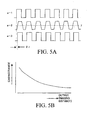
- a waveform a-1 in FIG. 5A is a rectangular waveform which is outputted from the rectangle wave generator 61 of the waveform detection part 60
- a waveform a-2 is a rectangular waveform which is an input to the preamplifier 63 and which is affected by the waveform distortion
- a waveform a-3 is an output of the preamplifier 63, the output of which is reformed using a threshold ⁇ to the waveform a-2.
- a waveform a-3 is a reformed pulse of the waveform a-2 and is delayed by a phase difference ⁇ t from the waveform a-1 according to the capacitance.
- the capacitance of the flat panel detector 21 is presumed by measuring a size of the output signal of the phase discriminator 64, and also it is possible to presume the distance (referred to as imaging distance below) between the flat panel detector 21 and the body surface of the patient by obtaining the value of the capacitance while the X-ray detecting part 2 moves.
- patient characteristics such as a patient's shape, age, sex and degree of obesity, affect the capacitance, and an error caused by a change of the capacitance can occur to the imaging distance to be presumed.
- the capacitance changes according to environment around the X-ray detecting part 2 and the patient 150. Especially an error resulting from humidity can be important.
- the patient characteristics and the environment such as the humidity or temperature, may be corrected.
- the memory circuit 68 in the distance detection part 6 in FIG. 4 has a capacitance-imaging distance memory area where a relationship between an imaging distance which is set to a general patient and the capacitance which is presumed based on the output signal from the waveform detection part 60 is stored.
- the memory circuit 68 further has a patient information memory area where the patient information, such as a diagnosis part, age, sex and degree of obesity of the patient 150 is stored, and an environment information memory area where the environment information, such as the humidity or the temperature, around the flat panel detector 21 is stored.
- the memory circuit 68 further includes a correction coefficient memory area where a correction coefficient of the capacitance to the patient information or the environment information.
- the memory circuit 68 includes a detection output-capacitance data memory area where a relationship between the detection output from the waveform detection part 60 shown in FIG. 4 and the capacitance of the capacitance sensor 261 is stored in advance.
- the general data of the above mentioned relationship between the imaging distance and the capacitance and the correction coefficient of the capacitance to the patient information and the environment information can be obtained based on a plurality of sets of data which are accumulated in past X-ray imaging, or a phantom can be used instead.
- Data of the relationship between the output of the phase discriminator 64 and the capacitance can be obtained by performing a basic experimentation in advance.
- the CPU 67 receives the output of the contact detection circuit 66 and the measured temperature value and the humidity value from the temperature and humidity sensor 263 in addition to the output signal from the phase discriminator 64 in the waveform detection part 60.
- the capacitance is calculated based on this output signal and the relationship data between the detection output and the capacitance stored in the detection output-capacitance data memory area.
- the capacitance is corrected to obtain corrected capacitance (referred to as corrected capacitance) is calculated by the correction coefficient selected from a plurality of correction coefficients stored in correction coefficient memory area based on the patient information data and the environment information stored in the patient information memory area and the environment information memory area.
- the CPU 67 calculates the imaging distance based on the relationship data stored in the capacitance-imaging distance memory area. When the calculated imaging distance is a first value ⁇ or a second value ⁇ , the CPU 67 supplies an approach signal to the system controller 10.
- the image process memory part 7 has a function to generate the X-ray image data to be displayed in the display part 8.
- the image process memory part 7 includes an image-processing circuit 71 for performing image processing to the X-ray projection data outputted from the projection data creating part 13.
- the image process memory part 7 further includes an image data memory circuit 72 for memorizing the above-mentioned X-ray projection data and the X-ray image data after image processing.
- the image-processing circuit 71 performs an image processing for generating DSA image data based on subtraction between contrast image data and mask image data which are obtained before and after contrast agent is injected, long image data and 3D image data, for example.
- the operation part 9 is an input device, such as a keyboard, a trackball, a joystick, a mouse, or a display panel or an interactive interface having various switches, etc, for example.
- the operation part 9 is used for inputting the patient information, for setting the first value ⁇ indicating a deceleration point of the moving speed of the X-ray detecting part 2 and the second value ⁇ indicating a stop point of the X-ray detecting part 2, for inputting a start instruction of the imaging, and for setting an appropriate X-ray imaging condition for the diagnosis part.
- the imaging condition includes a tube voltage, a tube current impressed to the X-ray tube 15, and a irradiation time of the X-ray, etc.
- the patient information includes age, sex, height, weight, degree of obesity, inspection part, past diagnostic history, etc.
- the patient information or the various imaging condition based on the patient information are automatically read from HIS (hospital information system) which is connected through the network, and an operator adjusts the information and the imaging condition, if necessary.
- HIS hospital information system
- the display part 8 is used for displaying the image data stored in the image data memory circuit 72 of the image process memory part 7.
- the display part 8 includes a data generation circuit 81 which creates the image data to be displayed, combining the image data and attached information, such as number or a letter.
- the display part 8 further includes a conversion circuit which creates a display signal, performing D/A conversion and TV format conversion to the image data or the attached information, and a monitor 83, such as a liquid crystal monitor or CRT monitor, which displays the display signal.
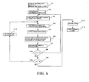
- FIG. 6 is a flow chart which shows the setting procedure of the imaging part.
- the X-ray imaging apparatus 100 When a power of X-ray imaging apparatus 100 is switched to ON, the X-ray imaging apparatus 100 starts to be connected to a server or HIS which is located in the same medical facilities through the network. Subsequently, when the operator inputs the patient ID of the patient 150 with the operation part 9, a CPU in the system controller 10 reads out the patient information and the imaging condition which correspond to the patient ID from the server or the HIS. The patient information and the imaging condition are memorized in a memory circuit in the system controller 10 and are displayed in a display panel of the operation part 9.
- the operator checks the above-mentioned information displayed on the display panel of the operation part 9 and adjusts them if needed.
- the operator selects the patient's 150 diagnosis part, age, sex, degree of obesity, etc. using an input device from the patient information.
- the selected information is stored in the patient information memory area in the memory circuit 68 of the distance detection part 6.
- the operator sets up a moving condition of the imaging part among the various imaging conditions displayed on the display panel of the operation part 9. For example, the deceleration point value ⁇ and the stop point value ⁇ ( ⁇ > ⁇ ) of the imaging part are set and stored in the memory circuit 68 via the CPU 67 of the distance detection part 6 (Step S1 of FIG. 6 ).
- the CPU67 of the distance detection part 6 receives the temperature value and humidity value which are obtained from the temperature and humidity sensor 263 positioned inside of the X-ray detecting part 2, and these values are saved in the environment information memory area of the memory circuit 68 (Step S2 of FIG. 6 ).
- the systems controller 10 supplies a command signal for rotating / moving the imaging part to the mechanism controller 33.
- the mechanism controller 33 which received the command signal supplies a control signal to the imaging part moving mechanism 31 to rotate the C-arm to a desired angle in a desired direction at a desired speed.
- the mechanism controller 33 supplies a control signal to the imaging part moving mechanism 31, and the X-ray detecting part 2 moves close to or far from the patient 150 at a desired speed (Step S3 of FIG. 6 ).
- the rectangle-wave generator 61 of the waveform detection part 60 supplies the rectangular pulse to the capacitance sensor 261 in a predetermined cycle through the driving circuit 62 while the X-ray detecting part 2 moves.
- the waveform distortion occurs to the rectangular pulse supplied to the capacitance sensor 261 having a capacitance.
- the rectangular pulse with the waveform distortion is amplified and reformed in the preamplifier 64 of the waveform detection part 60, and is inputted into the first input terminal of the phase discriminator 64.
- the rectangular pulse outputted from the rectangle wave generator 61 is inputted into the second input terminal of the phase discriminator 64.
- the phase discriminator 64 the rectangular pulse outputted from the rectangle wave generator 61 and the output of the preamplifier 63 are discriminated by phase, and are inputted into the CPU 67 (Step S4 of FIG. 6 ).
- the CPU 67 calculates the capacitance corresponding to the size of the output (direct-current component) of the phase discriminator 64 based on the relationship data of the detection output and the capacitance stored in the detection output-capacitance data memory area of the memory circuit 68 (Step S5 of FIG. 6 ).
- the CPU 67 reads out the temperature information and humidity information stored in the environment information memory area of the memory circuit 68, and the patient information, such as diagnosis part, body information (height, weight degree of obesity), age and sex stored in the patient information memory area of the memory circuit 68.
- the correction coefficient is selected from the correction coefficient information memory area based on the patient information and the environment information.
- the capacitance obtained in Step S5 is corrected using the correction coefficient to obtain the corrected capacitance (Step S6 of FIG. 6 ).
- the CPU 67 calculates the imaging distance Lx according to the corrected capacitance in Step S6 using the relationship information of the capacitance and the imaging distance stored in the capacitance-imaging distance memory area of the memory circuit 68 (Step S7 in FIG. 6 ).
- Step S8 in FIG. 6 the X-ray detecting part 2 moves at a constant speed to the patient 150, and Step S3 through S7 are repeated.
- the imaging distance Lx is not more than the deceleration imaging distance of the first value ⁇
- the imaging distance Lx is compared with the stop imaging distance of the second value ⁇ (Step S9 in FIG. 6 )
- Step S10 of FIG. 6 the imaging distance Lx is bigger than the stop imaging distance of the second value ⁇
- the CPU67 supplies a first approach signal to the systems controller 10
- the mechanism controller 33 which received a command signal from the systems controller 10 based on the first approach signal controls the imaging part moving mechanism 31 and decelerates the speed of the X-ray detecting part 2 (Step S10 of FIG. 6 ). Step S4 and S10 are repeated.
- the CPU67 supplies the second approach signal to the systems controller 10, and the mechanism controller 33 which received a command signal from the systems controller 10 based on the second approach signal supplies a stop signal to the imaging part moving mechanism 31, and the movement of the X-ray detecting part 2 stops (Step S11 of FIG. 6 ).
- the X-ray detecting part 2 which moves at the constant speed towards a the patient 150 reaches the deceleration imaging distance, it starts to decelerate, and when the imaging distance reaches to the stop imaging distance, the X-ray detecting part 2 stops.
- the operator inputs the start command of the X-ray imaging with the operation part 9.
- the X-ray imaging starts by supplying the start command to the systems controller 10 (Step S12 of FIG. 6 ).
- the high voltage controller 41 of the high voltage generating part 4 receives the start command from the systems controller 10, controls the high voltage generator 42 based on the already set-up X-ray irradiation condition, impresses the high voltage to the X-ray tube 15 of the X-ray generating part 1, and irradiates the X-ray to the patient 150 through the X-ray limiting device 16.
- the X-ray which passes through the patient 150 is detected by the flat panel detector 21 of the X-ray detecting part 2 positioned behind the patient 150.
- the flat panel detector 21 including the X-ray detection elements 51 which are arranged in the line direction and the segment direction as shown in FIG. 2 .
- the X-ray detection elements 51 receives the X-ray which passes the patient 150, and the signal electric charge corresponding to intensity of the X-ray irradiation is accumulated in the charge accumulating capacitor 53 of the X-ray detection element 51.
- the gate driver 22 to which a clock pulse is supplied from the systems controller 10 reads the signal electric charge accumulated in the charge accumulating capacitor 53 of the X-ray detection element 51 by supplying the driving pulse to the flat panel detector 21.
- the read out signal electric charge is converted into the voltage signal in the electric charge / voltage converter 23 in the projection data creating part 13 shown in FIG. 1 .
- the voltage signal is changed into a digital signal in the A/D converter 24, and is temporally memorized as projection data in a memory circuit of the parallel serial converter 25.
- the systems controller 10 reads the projection data in order serially per line, and stores the projection data as 2-dimensional projection data in the projection data memory are of the image data memory circuit 72 of the image process memory part 7.
- the image-processing circuit 71 of the image process memory part 7 reads the 2-dimensional projection data stored in the image data memory circuit 72, creates the image data by performing image processing, such as outline emphasis and gradation change, if needed, and stores the created image data in the image data memory are of the image data memory circuit 72.
- the systems controller 10 reads the image data stored in the image data memory circuit 72, and displays the image data on the monitor 83 of the display part 8.
- the systems controller 10 reads the image data stored in the image data memory circuit 72, and in the data generation circuit 81 for a display of the display part 8, the attached information, such as number or a letter, is combined to the image data, and the combined data is supplied to a conversion circuit 82.
- the conversion circuit 82 the D/A conversion and the TV format conversion are performed on the combined data, and the converted data is displayed on the monitor 83.
- the imaging distance to the closest part of the patient can be set according to the shape of the patient surface.
- the imaging distance can be appropriately set. Furthermore, when the correction of the capacitance is performed based on a database created in advance, the capacitance can be corrected stably and simply.
- the X-ray detecting part can be moved to a desired position to the patient without contact, and it is possible to obtain clear image data efficiently.
- FIG. 8B A modification of the capacitance sensor is explained with reference to FIG. 8A through 8C .
- a capacitance sensing element 275 is divided into four elements.
- a carbon sheet 276 is also divided into four sheets.
- the capacitance between each carbon sheet 276 and the basic capacitance element 272 is obtained by each capacitance detection circuit 27, and the imaging distance is measured.
- Two lines of the division of the capacitance sensing elements are positioned along the arrangement of the X-ray detection elements in the line direction and the segment direction.
- the carbon sheet may be positioned such that at least part of the carbon sheet overlaps the X-ray detection plane (indicated as a broken line) of the flat panel detector.
- a plurality of the capacitance sensing elements are adapted, it is possible to measure the imaging distance appropriately.
- the embodiment and the modification are mentioned above, however the embodiment and the modification may be modified.
- the embodiment the case where the X-ray detecting part moves to the patient is explained, the embodiment ant the modification may be applied to a case where the X-ray generating part may be move to the patient.
- the line of the division may not be positioned along the arrangement of the X-ray detection elements.
- the basic capacitance element may be adjusted instead of grounded.
- the patient information may not be limited to the patient's shape, age, sex and degree of obesity.
- the flat panel detector is explained for detecting the X-ray, an I.I and an X-ray TV may be used instead.
- the phase discriminating method for measuring the influence of the capacitance is explained, other method may be used.
- the angio X-ray imaging apparatus including the C-arm is mainly explained, other X-ray imaging apparatus, such as RF X-ray imaging apparatus, may be used.
- stop point ⁇ may be used.
Landscapes
- Health & Medical Sciences (AREA)
- Life Sciences & Earth Sciences (AREA)
- Medical Informatics (AREA)
- Engineering & Computer Science (AREA)
- Physics & Mathematics (AREA)
- Radiology & Medical Imaging (AREA)
- Surgery (AREA)
- Nuclear Medicine, Radiotherapy & Molecular Imaging (AREA)
- Optics & Photonics (AREA)
- Pathology (AREA)
- Biophysics (AREA)
- Biomedical Technology (AREA)
- Heart & Thoracic Surgery (AREA)
- Molecular Biology (AREA)
- High Energy & Nuclear Physics (AREA)
- Animal Behavior & Ethology (AREA)
- General Health & Medical Sciences (AREA)
- Public Health (AREA)
- Veterinary Medicine (AREA)
- General Physics & Mathematics (AREA)
- Apparatus For Radiation Diagnosis (AREA)
- Measurement Of Length, Angles, Or The Like Using Electric Or Magnetic Means (AREA)
Claims (14)
- Röntgenabbildungsgerät, umfassend:eine Röntgenbestrahlungseinheit (1), die derart konfiguriert ist, um Röntgenstrahler auf ein Objekt zu strahlen;eine Röntgenerfassungseinheit (2), die derart konfiguriert ist, um ausgestrahlte Röntgenstrahlen zu erfassen;eine Abbildungserzeugungseinheit (7), die derart konfiguriert ist, um Röntgenabbildungsdaten basierend auf den von der Röntgenerfassungseinheit erfassten Daten zu erzeugen;ein sich bewegender Mechanismus (3), der derart konfiguriert ist, um die Röntgenerfassungseinheit zum Objekt hin zu bewegen;eine Kapazitanzerfassungseinheit (261, 262), einschließlich einer Elektrode (273), die derart konfiguriert ist, um einen Kapazitanzwert der Röntgenerfassungseinheit durch die Elektrode zu erhalten; undeine Abstandsmessungseinheit (6), die derart konfiguriert ist, um den Abstand zwischen dem Objekt (150) und der Röntgenerfassungseinheit basierend auf dem Kapazitanzwert zu messen, dadurch gekennzeichnet, dass die Elektrode (273) ein Kohleblatt ist, das derart positioniert ist, um den gesamten Bereich einer Erfassungsebene der Röntgenerfassungseinheit abzudecken.
- Röntgenabbildungsgerät nach Anspruch 1, wobei die Elektrode in eine Vielzahl von Elektroden (276) unterteilt ist und die Kapazitanzerfassungseinheit derart angeordnet ist, um Kapazitanzwerte der Vielzahl der Elektroden zu erhalten.
- Röntgenabbildungsgerät nach Anspruch 2, wobei die Elektrode in vier Elektroden unterteilt ist.
- Röntgenabbildungsgerät nach Anspruch 1, 2 oder 3, wobei die Röntgenerfassungseinheit einen Flachelementdetektor (21) umfasst, in dem eine Vielzahl von Röntgenerfassungselementen zweidimensional angeordnet ist.
- Röntgenabbildungsgerät nach Anspruch 4, wobei die Elektrode entlang einer Linie derart unterteilt ist, dass die Linie entlang einer Anordnungsrichtung von Röntgenerfassungselementen positioniert ist.
- Röntgenabbildungsgerät nach einem der vorstehenden Ansprüche, ferner umfassend:ein Bearbeitungsmittel (67), das derart konfiguriert ist, um den Kapazitanzwert basierend auf Informationen über das Objekt oder dessen Umgebung zu korrigieren.
- Röntgenabbildungsgerät nach einem der vorstehenden Ansprüche, wobei der Bewegungsmechanismus derart angeordnet ist, um die Röntgenerfassungseinheit basierend auf dem gemessenen Abstand anzuhalten, bevor die Röntgenerfassungseinheit das Objekt kontaktiert.
- Röntgenabbildungsgerät nach einem der vorstehenden Ansprüche, wobei der Bewegungsmechanismus derart angeordnet ist, um eine Bewegungsgeschwindigkeit der Röntgenerfassungseinheit basierend auf dem gemessenen Abstand zu verändern.
- Röntgenabbildungsgerät nach einem der vorstehenden Ansprüche, umfassend:eine Umgebungserfassungseinheit (263), die derart konfiguriert ist, um Umgebungsinformationen um das Objekt herum zu erhalten; undeine Kapazitanzkorrektureinheit, die derart konfiguriert ist, um den Kapazitanzwert basierend auf den Umgebungsinformationen zu korrigieren; wobeidie Abstandsmessungseinheit derart konfiguriert ist, um den Abstand zwischen dem Objekt und der Röntgenerfassungseinheit basierend auf dem korrigierten Kapazitanzwert zu messen.
- Röntgenabbildungsgerät nach einem der vorstehenden Ansprüche, umfassend:ein Eingabegerät, das derart konfiguriert ist, um Informationen über das Objekt einzugeben;und eine Kapazitanzkorrektureinheit, die derart konfiguriert ist, um den Kapazitanzwert basierend auf den Objektinformationen zu korrigieren; wobeidie Abstandsmessungseinheit derart konfiguriert ist, um den Abstand zwischen dem Objekt und der Röntgenerfassungseinheit basierend auf dem korrigierten Kapazitanzwert zu messen.
- Röntgenabbildungsgerät nach Anspruch 10, wobei die Objektinformationen wenigstens eins der Nachfolgenden umfasst: die Gestalt, das Alter, Geschlecht und das Ausmaß der Fettleibigkeit des Objekts.
- Verfahren zum Bewegen eines Röntgendetektors, umfassend:das Bestrahlen mit Röntgenstrahlen eines Objekts durch eine Röntgenbestrahlungseinheit;das Erfassen der ausgestrahlten Röntgenstrahlen durch eine Röntgenerfassungseinheit;das Erzeugen von Röntgenabbildungsdaten basierend auf den in der Erfassungseinheit erfassten Daten;das Bewegen der Röntgenerfassungseinheit zum Objekt hin;das Erhalten eines Kapazitanzwerts der Röntgenerfassungseinheit durch eine Elektrode; unddas Messen eines Abstands zwischen dem Objekt und der Röntgenerfassungseinheit basierend auf dem Kapazitanzwert, dadurch gekennzeichnet, dass die Elektrode ein Kohleblatt ist, das derart positioniert ist, um den gesamten Bereich einer Erfassungsebene der Röntgenerfassungseinheit abzudecken.
- Verfahren zum Bewegen eines Röntgendetektors nach Anspruch 12, umfassend:das Erhalten von Umgebungsinformationen um das Objekt herum;das Korrigieren des Kapazitanzwerts basierend auf den Umgebungsinformationen; unddas Messen des Abstands zwischen dem Objekt und der Röntgenerfassungseinheit basierend auf dem korrigierten Kapazitanzwert.
- Verfahren zum Bewegen eines Röntgendetektors nach Anspruch 12 oder 13, umfassend:die Eingabe der Informationen über das Objekt;das Korrigieren des Kapazitanzwerts basierend auf den Objektinformationen; unddas Messen des Abstands zwischen dem Objekt und der Röntgenerfassungseinheit basierend auf dem korrigierten Kapazitanzwert.
Applications Claiming Priority (2)
| Application Number | Priority Date | Filing Date | Title |
|---|---|---|---|
| JP2003349433A JP4157455B2 (ja) | 2003-10-08 | 2003-10-08 | X線診断装置及び撮像系移動制御方法 |
| JP2003349433 | 2003-10-08 |
Publications (2)
| Publication Number | Publication Date |
|---|---|
| EP1522261A1 EP1522261A1 (de) | 2005-04-13 |
| EP1522261B1 true EP1522261B1 (de) | 2012-04-18 |
Family
ID=34309238
Family Applications (1)
| Application Number | Title | Priority Date | Filing Date |
|---|---|---|---|
| EP04256243A Expired - Lifetime EP1522261B1 (de) | 2003-10-08 | 2004-10-08 | Röntgenabbildungsgerät und Verfahren zur Bewegung eines Röntgenstrahlungsdetektors |
Country Status (4)
| Country | Link |
|---|---|
| US (1) | US7172340B2 (de) |
| EP (1) | EP1522261B1 (de) |
| JP (1) | JP4157455B2 (de) |
| CN (1) | CN100399995C (de) |
Families Citing this family (26)
| Publication number | Priority date | Publication date | Assignee | Title |
|---|---|---|---|---|
| JP4552572B2 (ja) * | 2004-09-16 | 2010-09-29 | 株式会社島津製作所 | 医用診断装置 |
| JP4631367B2 (ja) * | 2004-09-16 | 2011-02-16 | 株式会社島津製作所 | 医用診断装置 |
| US7324628B2 (en) * | 2005-04-22 | 2008-01-29 | General Electric Company | Method of testing a medical imaging device |
| DE102005049106A1 (de) * | 2005-10-13 | 2007-04-19 | Siemens Ag | Medizinisches Bildgebungssystem und Kollisionsschutzverfahren mit regelbarem Arm |
| CN100486523C (zh) * | 2005-11-23 | 2009-05-13 | 北京东方逸腾数码医疗设备技术有限公司 | 用于医用x射线设备的非接触防撞装置 |
| JP4640153B2 (ja) * | 2005-12-14 | 2011-03-02 | 株式会社島津製作所 | X線装置 |
| JP4840011B2 (ja) * | 2006-07-28 | 2011-12-21 | 株式会社島津製作所 | X線装置 |
| FR2904750B1 (fr) * | 2006-08-03 | 2008-10-17 | Gen Electric | Procede de reconstruction tridimensionnelle d'une enveloppe exterieure d'un corps d'un appareil a rayons x |
| CN200951266Y (zh) * | 2006-08-03 | 2007-09-26 | 邱炎雄 | 一种防护装置 |
| US8269176B2 (en) * | 2006-11-20 | 2012-09-18 | Koninklijke Philips Electronics N.V. | Detector head proximity sensing and collision avoidance apparatuses and methods |
| DE102007025935A1 (de) * | 2007-06-04 | 2008-12-24 | Siemens Ag | Kollisionsschutzvorrichtung für eine Patientenliege eines medizinischen Röntgengeräts, Patientenliege mit einer Kollisionsschutzvorrichtung und Röntgengerät |
| JP4826547B2 (ja) * | 2007-06-19 | 2011-11-30 | 株式会社島津製作所 | X線診断装置 |
| US8552392B2 (en) * | 2007-07-27 | 2013-10-08 | Fujifilm Corporation | Cassette and radiation image capturing system |
| JP4985484B2 (ja) * | 2008-03-07 | 2012-07-25 | 株式会社島津製作所 | X線撮影装置 |
| JP4968160B2 (ja) * | 2008-04-18 | 2012-07-04 | 株式会社島津製作所 | 医用診断装置 |
| RU2519353C2 (ru) * | 2008-08-13 | 2014-06-10 | Конинклейке Филипс Электроникс Н.В. | Создание маски для кардиосубстракции |
| WO2010018500A1 (en) * | 2008-08-13 | 2010-02-18 | Koninklijke Philips Electronics N.V. | Dynamical visualization of coronary vessels and myocardial perfusion information |
| JP5627373B2 (ja) * | 2010-09-28 | 2014-11-19 | キヤノン株式会社 | 撮像装置、その制御方法及びプログラム |
| US10278593B2 (en) | 2012-06-21 | 2019-05-07 | Siemens Healthcare Gmbh | Adaptive control of monitoring devices |
| CN105025836B (zh) | 2013-03-15 | 2017-06-13 | 麦迪盖德有限公司 | 医疗装置导航系统 |
| KR102328117B1 (ko) | 2014-12-08 | 2021-11-17 | 삼성전자주식회사 | 엑스선 장치 및 시스템 |
| US10925562B2 (en) | 2017-02-22 | 2021-02-23 | General Electric Company | Variable SID imaging |
| US11241206B2 (en) * | 2017-03-21 | 2022-02-08 | Canon Medical Systems Corporation | X-ray imaging apparatus |
| US20190000407A1 (en) * | 2017-06-30 | 2019-01-03 | General Electric Company | Variable distance imaging |
| CN111513738B (zh) * | 2020-04-10 | 2023-08-01 | 北京东软医疗设备有限公司 | 血管造影方法、装置、设备及系统 |
| JP7468373B2 (ja) * | 2021-01-19 | 2024-04-16 | 株式会社島津製作所 | X線撮影装置 |
Family Cites Families (22)
| Publication number | Priority date | Publication date | Assignee | Title |
|---|---|---|---|---|
| DE2646638C2 (de) * | 1976-10-15 | 1986-08-14 | Siemens AG, 1000 Berlin und 8000 München | Zahnärztliche Röntgendiagnostikeinrichtung |
| US4979197A (en) * | 1986-05-22 | 1990-12-18 | Troxler Electronic Laboratories, Inc. | Nuclear radiation apparatus and method for dynamically measuring density of test materials during compaction |
| JPH0763514B2 (ja) * | 1988-09-26 | 1995-07-12 | 三菱電機株式会社 | 医療装置の衝突防止装置 |
| DE4004348A1 (de) * | 1990-02-13 | 1991-08-14 | Philips Patentverwaltung | Anordnung zum abtasten einer roentgenaufnahme |
| DE4126168A1 (de) * | 1990-08-20 | 1992-02-27 | Siemens Ag | Medizinisches diagnose- oder therapiegeraet |
| US5651044A (en) * | 1995-10-02 | 1997-07-22 | General Electric Company | Capacitive proximity detector for radiation imager position control |
| US5654997A (en) * | 1995-10-02 | 1997-08-05 | General Electric Company | Ultrasonic ranging system for radiation imager position control |
| US5805664A (en) * | 1995-10-02 | 1998-09-08 | General Electric Company | Imager control system with contact detector |
| JP4067565B2 (ja) * | 1995-11-30 | 2008-03-26 | コーニンクレッカ フィリップス エレクトロニクス エヌ ヴィ | 医療用診断装置用の電磁気的対象検出器 |
| DE69721906T2 (de) * | 1996-02-26 | 2004-05-19 | Koninklijke Philips Electronics N.V. | Objektdetektor und angeschlossene antriebsvorrichtung für ein medizinisch diagnostisches gerät |
| US5805658A (en) * | 1996-12-31 | 1998-09-08 | General Electric Company | Methods and apparatus for detecting gantry interference in a computed tomography system |
| CN2289357Y (zh) * | 1997-03-14 | 1998-08-26 | 武汉大学 | X射线静电扫描仪 |
| US5912943A (en) * | 1997-11-26 | 1999-06-15 | Picker International, Inc. | Cooling system for a sealed housing positioned in a sterile environment |
| US6548796B1 (en) * | 1999-06-23 | 2003-04-15 | Regents Of The University Of Minnesota | Confocal macroscope |
| EP1162915A1 (de) * | 1999-12-24 | 2001-12-19 | Koninklijke Philips Electronics N.V. | Elektromagnetischer objektfühler versehen mit einer zusatzelektrode und verwendet in einem medizinischem röntgengerät |
| JP2001208504A (ja) | 2000-01-28 | 2001-08-03 | Hitachi Medical Corp | 静電容量型距離センサ及びこれを用いた医用診断装置の障害物検出システム |
| JP4298119B2 (ja) | 2000-02-29 | 2009-07-15 | 株式会社日立メディコ | 医用診断装置 |
| JP4408530B2 (ja) | 2000-05-29 | 2010-02-03 | 株式会社日立メディコ | 医用診断装置の障害物検出システム |
| US6661240B1 (en) * | 2000-10-04 | 2003-12-09 | General Electric Co. | Methods and systems for capacitive motion sensing and position control |
| US6700392B2 (en) * | 2001-02-02 | 2004-03-02 | Wayne C. Haase | Digital measurement circuit and system using a grounded capacitive sensor |
| FR2844349B1 (fr) * | 2002-09-06 | 2005-06-24 | Nanotec Solution | Detecteur de proximite par capteur capacitif |
| JP3884377B2 (ja) * | 2002-12-27 | 2007-02-21 | ジーイー・メディカル・システムズ・グローバル・テクノロジー・カンパニー・エルエルシー | X線撮影装置 |
-
2003
- 2003-10-08 JP JP2003349433A patent/JP4157455B2/ja not_active Expired - Fee Related
-
2004
- 2004-10-06 US US10/958,391 patent/US7172340B2/en not_active Expired - Lifetime
- 2004-10-08 CN CNB2004100874596A patent/CN100399995C/zh not_active Expired - Fee Related
- 2004-10-08 EP EP04256243A patent/EP1522261B1/de not_active Expired - Lifetime
Also Published As
| Publication number | Publication date |
|---|---|
| JP2005110975A (ja) | 2005-04-28 |
| CN1605321A (zh) | 2005-04-13 |
| US20050117703A1 (en) | 2005-06-02 |
| JP4157455B2 (ja) | 2008-10-01 |
| EP1522261A1 (de) | 2005-04-13 |
| US7172340B2 (en) | 2007-02-06 |
| CN100399995C (zh) | 2008-07-09 |
Similar Documents
| Publication | Publication Date | Title |
|---|---|---|
| EP1522261B1 (de) | Röntgenabbildungsgerät und Verfahren zur Bewegung eines Röntgenstrahlungsdetektors | |
| JP6200839B2 (ja) | 乳房厚測定装置、乳房厚測定方法及び放射線撮影システム | |
| US9301728B2 (en) | X-ray apparatus | |
| EP1163880A2 (de) | Verfahren und Gerät zur Bestimmung des Quellen-Bild-Abstandes in einem digitalen Abbildungssystem | |
| US11166694B2 (en) | Positioning support apparatus, radiographic imaging system, and storage medium | |
| JP2009082372A (ja) | 放射線撮影装置 | |
| JP2011147615A (ja) | X線透視撮影装置 | |
| US20040258207A1 (en) | Radiographic apparatus | |
| EP1378200B1 (de) | Röntgendiagnostikgerät | |
| JP2015002938A (ja) | X線透視撮影装置 | |
| US20040257744A1 (en) | Collision avoidance system and method | |
| EP3605073B1 (de) | Röntgenstrahltransmissionsinspektionsvorrichtung und röntgenstrahltransmissionsinspektionsverfahren | |
| US5982848A (en) | X-ray diagnosis machine having displaceable measurement field | |
| US6375354B1 (en) | Method and system for determining a variable lateral center-to-center setpoint for a digital imaging system | |
| JP2004202026A (ja) | X線診断装置及びx線撮影方法 | |
| JP4651412B2 (ja) | X線画像診断装置 | |
| JP2006136500A (ja) | X線診断装置及び画像データ生成方法 | |
| JP2006218216A (ja) | X線診断装置及びx線撮影方法 | |
| JP2002514949A (ja) | 医療診断装置用の試験電極を有する電磁対象検出器 | |
| US12496032B2 (en) | X-ray imaging apparatus and X-ray imaging method | |
| JP4772355B2 (ja) | X線診断装置 | |
| US20240423568A1 (en) | Dynamic analysis system, correction apparatus, storage medium, and dynamic imaging apparatus | |
| JP4504034B2 (ja) | X線診断装置 | |
| JP3364042B2 (ja) | 高速x線ctシステムの検出器位置決め装置 | |
| CN221980766U (zh) | 一种医用x射线设备 |
Legal Events
| Date | Code | Title | Description |
|---|---|---|---|
| PUAI | Public reference made under article 153(3) epc to a published international application that has entered the european phase |
Free format text: ORIGINAL CODE: 0009012 |
|
| 17P | Request for examination filed |
Effective date: 20041022 |
|
| AK | Designated contracting states |
Kind code of ref document: A1 Designated state(s): AT BE BG CH CY CZ DE DK EE ES FI FR GB GR HU IE IT LI LU MC NL PL PT RO SE SI SK TR |
|
| AX | Request for extension of the european patent |
Extension state: AL HR LT LV MK |
|
| AKX | Designation fees paid |
Designated state(s): DE NL |
|
| 17Q | First examination report despatched |
Effective date: 20100727 |
|
| REG | Reference to a national code |
Ref country code: DE Ref legal event code: R079 Ref document number: 602004037397 Country of ref document: DE Free format text: PREVIOUS MAIN CLASS: A61B0006100000 Ipc: G01B0007020000 |
|
| RIC1 | Information provided on ipc code assigned before grant |
Ipc: A61B 6/10 20060101ALI20110831BHEP Ipc: G01B 7/02 20060101AFI20110831BHEP Ipc: H03K 17/955 20060101ALI20110831BHEP Ipc: G01B 7/06 20060101ALI20110831BHEP |
|
| GRAP | Despatch of communication of intention to grant a patent |
Free format text: ORIGINAL CODE: EPIDOSNIGR1 |
|
| GRAS | Grant fee paid |
Free format text: ORIGINAL CODE: EPIDOSNIGR3 |
|
| GRAA | (expected) grant |
Free format text: ORIGINAL CODE: 0009210 |
|
| AK | Designated contracting states |
Kind code of ref document: B1 Designated state(s): DE NL |
|
| REG | Reference to a national code |
Ref country code: DE Ref legal event code: R081 Ref document number: 602004037397 Country of ref document: DE Owner name: TOSHIBA MEDICAL SYSTEMS CORPORATION, OTAWARA-S, JP Free format text: FORMER OWNERS: KABUSHIKI KAISHA TOSHIBA, TOKIO/TOKYO, JP; TOSHIBA MEDICAL SYSTEMS CORPORATION, OTAWARA-SHI, TOCHIGI-KEN, JP |
|
| REG | Reference to a national code |
Ref country code: DE Ref legal event code: R096 Ref document number: 602004037397 Country of ref document: DE Effective date: 20120614 |
|
| REG | Reference to a national code |
Ref country code: NL Ref legal event code: T3 |
|
| PLBE | No opposition filed within time limit |
Free format text: ORIGINAL CODE: 0009261 |
|
| STAA | Information on the status of an ep patent application or granted ep patent |
Free format text: STATUS: NO OPPOSITION FILED WITHIN TIME LIMIT |
|
| 26N | No opposition filed |
Effective date: 20130121 |
|
| REG | Reference to a national code |
Ref country code: DE Ref legal event code: R097 Ref document number: 602004037397 Country of ref document: DE Effective date: 20130121 |
|
| REG | Reference to a national code |
Ref country code: NL Ref legal event code: PD Owner name: TOSHIBA MEDICAL SYSTEMS CORPORATION; JP Free format text: DETAILS ASSIGNMENT: VERANDERING VAN EIGENAAR(S), OVERDRACHT; FORMER OWNER NAME: TOSHIBA MEDICAL SYSTEMS CORPORATION Effective date: 20160627 |
|
| REG | Reference to a national code |
Ref country code: DE Ref legal event code: R081 Ref document number: 602004037397 Country of ref document: DE Owner name: TOSHIBA MEDICAL SYSTEMS CORPORATION, OTAWARA-S, JP Free format text: FORMER OWNERS: KABUSHIKI KAISHA TOSHIBA, TOKIO/TOKYO, JP; TOSHIBA MEDICAL SYSTEMS CORPORATION, OTAWARA-SHI, TOCHIGI-KEN, JP Ref country code: DE Ref legal event code: R082 Ref document number: 602004037397 Country of ref document: DE Representative=s name: HOFFMANN - EITLE PATENT- UND RECHTSANWAELTE PA, DE |
|
| PGFP | Annual fee paid to national office [announced via postgrant information from national office to epo] |
Ref country code: DE Payment date: 20171004 Year of fee payment: 14 |
|
| PGFP | Annual fee paid to national office [announced via postgrant information from national office to epo] |
Ref country code: NL Payment date: 20171016 Year of fee payment: 14 |
|
| REG | Reference to a national code |
Ref country code: DE Ref legal event code: R119 Ref document number: 602004037397 Country of ref document: DE |
|
| REG | Reference to a national code |
Ref country code: NL Ref legal event code: MM Effective date: 20181101 |
|
| PG25 | Lapsed in a contracting state [announced via postgrant information from national office to epo] |
Ref country code: DE Free format text: LAPSE BECAUSE OF NON-PAYMENT OF DUE FEES Effective date: 20190501 Ref country code: NL Free format text: LAPSE BECAUSE OF NON-PAYMENT OF DUE FEES Effective date: 20181101 |