EP1519471B1 - Synchronmotor mit Dauermagneten - Google Patents
Synchronmotor mit Dauermagneten Download PDFInfo
- Publication number
- EP1519471B1 EP1519471B1 EP04030799A EP04030799A EP1519471B1 EP 1519471 B1 EP1519471 B1 EP 1519471B1 EP 04030799 A EP04030799 A EP 04030799A EP 04030799 A EP04030799 A EP 04030799A EP 1519471 B1 EP1519471 B1 EP 1519471B1
- Authority
- EP
- European Patent Office
- Prior art keywords
- rotor
- iron core
- permanent magnets
- rotor iron
- synchronous motor
- Prior art date
- Legal status (The legal status is an assumption and is not a legal conclusion. Google has not performed a legal analysis and makes no representation as to the accuracy of the status listed.)
- Expired - Lifetime
Links
- 230000001360 synchronised effect Effects 0.000 title claims description 110
- XEEYBQQBJWHFJM-UHFFFAOYSA-N Iron Chemical group [Fe] XEEYBQQBJWHFJM-UHFFFAOYSA-N 0.000 claims description 268
- 229910000831 Steel Inorganic materials 0.000 claims description 77
- 239000010959 steel Substances 0.000 claims description 77
- 239000004020 conductor Substances 0.000 claims description 54
- 229910052782 aluminium Inorganic materials 0.000 claims description 51
- XAGFODPZIPBFFR-UHFFFAOYSA-N aluminium Chemical compound [Al] XAGFODPZIPBFFR-UHFFFAOYSA-N 0.000 claims description 51
- 238000004512 die casting Methods 0.000 claims description 36
- 241000555745 Sciuridae Species 0.000 claims description 25
- 239000007858 starting material Substances 0.000 claims description 25
- 238000004804 winding Methods 0.000 claims description 17
- QNRATNLHPGXHMA-XZHTYLCXSA-N (r)-(6-ethoxyquinolin-4-yl)-[(2s,4s,5r)-5-ethyl-1-azabicyclo[2.2.2]octan-2-yl]methanol;hydrochloride Chemical compound Cl.C([C@H]([C@H](C1)CC)C2)CN1[C@@H]2[C@H](O)C1=CC=NC2=CC=C(OCC)C=C21 QNRATNLHPGXHMA-XZHTYLCXSA-N 0.000 claims description 3
- 230000000052 comparative effect Effects 0.000 description 105
- 230000004907 flux Effects 0.000 description 102
- 229910052742 iron Inorganic materials 0.000 description 37
- 238000009826 distribution Methods 0.000 description 30
- 230000003449 preventive effect Effects 0.000 description 13
- 230000004888 barrier function Effects 0.000 description 10
- 230000002093 peripheral effect Effects 0.000 description 9
- 239000000463 material Substances 0.000 description 8
- 238000000034 method Methods 0.000 description 8
- 238000002788 crimping Methods 0.000 description 7
- 238000004519 manufacturing process Methods 0.000 description 5
- 230000004323 axial length Effects 0.000 description 4
- 229910001172 neodymium magnet Inorganic materials 0.000 description 4
- 229910052761 rare earth metal Inorganic materials 0.000 description 4
- 150000002910 rare earth metals Chemical class 0.000 description 4
- 230000015572 biosynthetic process Effects 0.000 description 3
- 210000000080 chela (arthropods) Anatomy 0.000 description 3
- 238000003780 insertion Methods 0.000 description 3
- 230000037431 insertion Effects 0.000 description 3
- 238000010030 laminating Methods 0.000 description 3
- 238000003475 lamination Methods 0.000 description 3
- 230000002265 prevention Effects 0.000 description 3
- 230000009467 reduction Effects 0.000 description 3
- 101150079087 Arfgef2 gene Proteins 0.000 description 2
- 230000008859 change Effects 0.000 description 2
- 230000003247 decreasing effect Effects 0.000 description 2
- 238000013461 design Methods 0.000 description 2
- 230000002349 favourable effect Effects 0.000 description 2
- 238000000227 grinding Methods 0.000 description 2
- 230000009471 action Effects 0.000 description 1
- 238000004378 air conditioning Methods 0.000 description 1
- 238000013459 approach Methods 0.000 description 1
- 230000000712 assembly Effects 0.000 description 1
- 238000000429 assembly Methods 0.000 description 1
- 238000005266 casting Methods 0.000 description 1
- 239000002131 composite material Substances 0.000 description 1
- 238000001816 cooling Methods 0.000 description 1
- 230000001186 cumulative effect Effects 0.000 description 1
- 230000007547 defect Effects 0.000 description 1
- 230000000694 effects Effects 0.000 description 1
- 230000001747 exhibiting effect Effects 0.000 description 1
- 230000006872 improvement Effects 0.000 description 1
- 230000006698 induction Effects 0.000 description 1
- 239000000696 magnetic material Substances 0.000 description 1
- 229910052751 metal Inorganic materials 0.000 description 1
- 239000002184 metal Substances 0.000 description 1
- 238000003801 milling Methods 0.000 description 1
- 238000012986 modification Methods 0.000 description 1
- 230000004048 modification Effects 0.000 description 1
- 239000002245 particle Substances 0.000 description 1
- 238000003825 pressing Methods 0.000 description 1
- 230000008569 process Effects 0.000 description 1
- 238000009877 rendering Methods 0.000 description 1
- 230000004044 response Effects 0.000 description 1
- 238000000926 separation method Methods 0.000 description 1
- 238000007711 solidification Methods 0.000 description 1
- 230000008023 solidification Effects 0.000 description 1
Images


Classifications
-
- H—ELECTRICITY
- H02—GENERATION; CONVERSION OR DISTRIBUTION OF ELECTRIC POWER
- H02K—DYNAMO-ELECTRIC MACHINES
- H02K1/00—Details of the magnetic circuit
- H02K1/06—Details of the magnetic circuit characterised by the shape, form or construction
- H02K1/22—Rotating parts of the magnetic circuit
- H02K1/27—Rotor cores with permanent magnets
- H02K1/2706—Inner rotors
- H02K1/272—Inner rotors the magnetisation axis of the magnets being perpendicular to the rotor axis
- H02K1/274—Inner rotors the magnetisation axis of the magnets being perpendicular to the rotor axis the rotor consisting of two or more circumferentially positioned magnets
- H02K1/2753—Inner rotors the magnetisation axis of the magnets being perpendicular to the rotor axis the rotor consisting of two or more circumferentially positioned magnets the rotor consisting of magnets or groups of magnets arranged with alternating polarity
- H02K1/276—Magnets embedded in the magnetic core, e.g. interior permanent magnets [IPM]
-
- H—ELECTRICITY
- H02—GENERATION; CONVERSION OR DISTRIBUTION OF ELECTRIC POWER
- H02K—DYNAMO-ELECTRIC MACHINES
- H02K21/00—Synchronous motors having permanent magnets; Synchronous generators having permanent magnets
- H02K21/46—Motors having additional short-circuited winding for starting as an asynchronous motor
Definitions
- the present invention generally relates to a permanent magnet synchronous motor and, more particularly, to the synchronous motor generally used in a motor-driven compressor in a refrigerating system or an air conditioning system or any other industrially utilized electric appliance.
- a self-starting permanent magnet synchronous motor operates as an inductor motor at the time of starting thereof owing to a starter squirrel cage conductor and as a synchronous motor as rotating magnetic poles created by the permanent magnets are entrained by a rotating magnetic field formed by a stator winding and moving angularly at a synchronous speed upon arrival of the rotor at a speed approaching the synchronous speed.
- This synchronous motor has an excellent constant speed operating performance and an excellent high efficiency. In particular, various improvement have hitherto been made to a rotor structure of the synchronous motor.
- JP54009708A or US4403161 A discloses the prior art rotor structure for the self-starting permanent magnet synchronous motor.
- Fig. 6 illustrates the prior art rotor disclosed in the Japanese Patent Publication No. 59-23179B .
- reference numeral 1 represents a rotor
- reference numeral 2 represents a rotor iron core having a plurality of slots 3 defined therein adjacent an outer periphery thereof.
- Conductor bars 4 are disposed within those slots 3 and have their opposite ends shortcircuited by respective shortcircuit rings to thereby form a starter squirrel cage conductor.
- the shortcircuit rings (not shown) are made of an annular electroconductive material disposed on axially opposite ends of the rotor iron core and are connected with the conductor bars 4.
- a plurality of magnet retaining holes 5 are provided on an inner side of the conductor bars 4, with corresponding permanent magnets 6 embedded therein.
- Reference numeral 7 represents magnetic flux shortcircuit preventive slits that are spaced such a small distance P from the magnet retaining holes 5 that magnetic saturation can take place between the magnet retaining holes 5 and the slits 7 to thereby prevent the magnetic fluxes emanating from the permanent magnets from being shortcircuited between the different magnetic poles.
- Fig. 58 illustrates a longitudinal sectional view of the rotor used in the prior art self-starting synchronous motor disclosed in the Japanese Patent Publication No. 63-20105B and Fig. 59 illustrates a cross-sectional view taken along the line A-A' in Fig. 58 .
- reference numeral 11 represents a rotor
- reference numeral 12 represents a rotor iron core made up of a laminate of electromagnetic steel plates.
- Reference numeral 13 represents conductor bars having their opposite ends connected with respective shortcircuit rings 14 to thereby form a starter squirrel cage conductor.
- Reference numeral 15 represents permanent magnets embedded in the rotor iron core to form four rotor magnetic poles.
- Reference numeral 16 represents magnetic flux shortcircuit preventive slits each operable to prevent the magnetic flux between the neighboring permanent magnets of the different polarities from being shortcircuited.
- Reference numeral 17 represents an end plate disposed on each of axially opposite ends of the rotor iron core 2 by means of bolts to avoid any possible separation of the permanent magnets 5 from the rotor iron core 2.
- the prior art permanent magnet motor of the type provided with the cage conductor since the conductor bars and the permanent magnets are employed as rotatory drive elements, if the conductor bars and the permanent magnets are incorrectly positioned relative to each other, a force generated from the conductor bars and a force generated by the permanent magnets will be counteracted with each other and, therefore, no efficient rotatory drive will be achieved. Also, the permanent magnet motor provided with such a cage conductor requires a complicated and increased number of manufacturing steps since the permanent magnets and the conductor bars are provided in the rotor.
- US4322648A , US5097166A and US4845837A all disclose synchronous motors in accordance with the preamble of claim 1.
- EP0596353A discloses casting a rotor of an electric motor from a non-magnetic material containing small magnetisable particles whereby the rotor is exposed to a magnetic field during solidification.
- EP0447257A discloses a two-stator induction synchronous motor having a unitary rotor which has first and second permanent magnet rotor assemblies, each assembly having a pair of magnetic poles displaced 180° or 0° relative to the other assembly.
- the present invention is intended to solve those problems inherent in the prior art permanent magnet synchronous motor and is to increase the efficiency and simplify the manufacture of the synchronous motor of the type employing the permanent magnets.
- the invention consist in a synchronous motor which comprises:
- the width of the permanent magnets can be increased and, therefore, with no need to increase the axial length of the permanent magnets, the requires area of surface of the magnetic poles of the permanent magnets can be secured. Accordingly, there is no need to laminate thickness of the rotor iron core, thereby decreasing the cost.
- the inner diameter of the shortcircuit rings on one side where the permanent magnets are inserted may lie outside the magnet retaining holes in the rotor iron core, in which case the inner diametric dimension of one of the shortcircuit rings adjacent one end of the magnetic poles is chosen to be greater than the inner diametric dimension thereof adjacent the center point of the magnetic poles, and the inner diametric dimension of the other of the shortcircuit rings lies inwardly of the whole or a part of the magnet retaining holes.
- an end plate made of a non-magnetizable plate is preferably positioned between such other shortcircuit ring and the rotor iron core so as to cover the magnet retaining holes.
- the inner diameter of the shortcircuit rings on one side where the permanent magnets are inserted lies outside the magnet retaining holes in the rotor iron core, and the inner diametric dimension of one of the shortcircuit rings adjacent one end of the magnetic poles is chosen to be greater than the inner diametric dimension thereof adjacent the center point of the magnetic poles, whereas the inner diametric dimension of the other of the shortcircuit rings lies. Inwardly of the whole or a part of the magnet retaining holes. In such case, however, one or a plurality of electromagnetic steel plates of the rotor iron core adjacent the other shortcircuit ring is or are not formed with the magnet retaining holes.
- the inner diameter of the shortcircuit rings on one side where the permanent magnets are inserted may be of a shape lying along the magnet retaining holes in the rotor iron core.
- stator iron core is made up of a stator laminate of electromagnetic steel plates and the rotor iron core is also made up of a rotor laminate of electromagnetic steel plates
- stator laminate has a thickness about equal to that of the rotor laminate.
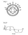
- Fig. 1 illustrates a transverse sectional view of a rotor used in a self-starting synchronous motor of a type utilizing permanent magnets according to a first comparative example to the present invention.
- reference numeral 21 represents a rotor
- reference numeral 22 represents a rotor iron core.
- the rotor iron core 22 has a plurality of slots 23 defined in an outer peripheral portion thereof for accommodating a corresponding number of conductor bars 24, which are integrally molded together with shortcircuit rings (not shown) at axially spaced opposite ends of the rotor iron core 22 by the use of any known aluminum die casting to thereby provide a starter squirrel cage conductor.
- Permanent magnets 26 are embedded in respective magnet retaining holes defined in the rotor iron core 23 at a location radially inwardly of a round row of the conductor bars 24.
- two plate-like permanent magnets 26 are butted end-to-end in a generally V-shaped configuration to form a single rotor magnetic pole and, since four permanent magnets are employed in the rotor, two rotor magnetic poles are formed.
- Reference characters T2 and T3 represents the interval between the neighboring slots 23 positioned adjacent the rotor magnetic poles defined by the permanent magnets, and reference character T4 represents the interval between the neighboring slots 23 positioned adjacent a center point between the rotor magnetic poles. In the illustrated example, the intervals T2 and T3 are chosen to be smaller than the interval T4.
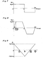
- Fig. 2 is a chart showing a pattern of distribution of magnetic flux densities in an air gap between the rotor and the stator, wherein the axis of ordinates represents the magnetic flux density B and the axis of abscissas represents the angle ⁇ of the air gap in a direction conforming to the direction of rotation of the rotor with the origin represented by the center point between the rotor magnetic pole.
- the intervals T2 and T3 are smaller than the interval T4 at the center points of the rotor magnetic poles, magnetic fluxes emanating from the permanent magnets 26 do hardly leak to the outer peripheral surface of the rotor 21 and, instead, leak to the outer peripheral surface adjacent the center points of the rotor magnetic poles.
- the pattern of distribution of the magnetic flux densities in the air gap between the stator and the rotor 21 represents a generally trapezoidal waveform or a generally sinusoidal waveform and, since as compared with a rectangular waveform the amount of change of the magnetic fluxes per unitary time increases, it is possible to increase the voltage induced across the winding of the stator.
- the slots in the rotor iron core are circumferentially spaced at regular intervals and have the same radial lengths as measured in a direction radially of the rotor iron core and, therefore, the pattern of distribution of the magnetic flux densities tends to represents a rectangular waveform.
- the intensity of the rotor magnetic poles brought about by the permanent magnets can be relatively grasped by measuring the magnitude of the voltage induced across the winding of the stator when the rotor is externally rotated while no voltage is applied to the motor.
- Fig. 7 The case in which the pattern Bg( ⁇ ) of distribution of the magnetic flux densities in the air gap represents a rectangular waveform Bg1 ( ⁇ ) is shown in Fig. 7
- Fig. 8 The case in which the pattern of distribution of the magnetic flux densities in the air gap represents a generally trapezoidal waveform Big2( ⁇ ) is shown in Fig. 8 .
- the axis of abscissas represents the angle ⁇ of the air gap in a direction conforming to the direction of rotation with the point of origin represented by the center point between the rotor magnetic poles.
- Bg ⁇ 2 ⁇ ⁇ tan ⁇ when 0 ⁇ ⁇ ⁇ BG ⁇ 2 ⁇ m / tan ⁇
- Bg ⁇ 2 ⁇ Bg ⁇ 2 ⁇ m ⁇ when Bg ⁇ 2 ⁇ m / tan ⁇ ⁇ ⁇ ⁇ ⁇ - B ⁇ 2 ⁇ m / tan ⁇
- B ⁇ 2 ⁇ - ⁇ tan ⁇ + ⁇ tan ⁇ when ⁇ ⁇ - Bg ⁇ 2 ⁇ m / tan ⁇ ⁇ ⁇ ⁇ ⁇ ⁇ ⁇
- stator winding is distributed over a region corresponding to one magnetic pole
- stator winding can be arranged intensively in a width of an angle ⁇ in a direction conforming to the direction of rotation corresponding to the single magnetic pole and the number of turns thereof assumed to be n.
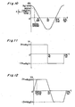
- the amount of the magnetic fluxes ⁇ 1(t) in the case where the pattern Bg( ⁇ ) of distribution of the magnetic flux densities in the air gap represents the rectangular waveform Bg1 ( ⁇ ) represents such a waveform as shown in Fig. 9 when Bg1( ⁇ ) of each of the equations (1) and (2) is substituted for Bg( ⁇ ) in the equation (7).
- the amount of the magnetic fluxed ⁇ 2(t) in the case of the trapezoidal waveform Big2( ⁇ ) represents such a waveform as shown in Fig. 10 when Bg1 ( ⁇ ) in each of the equations (4) and (5) is substituted for Bg( ⁇ ) in the equation (7).
- the axis of ordinates and the axis of abscissas in each of Figs. 9 and 10 represent the amount of the magnetic fluxes ⁇ and the time t, respectively.
- the waveform V1 (t) of the induced voltage in the case where the pattern of distribution of the magnetic flux densities in the air gap represents the rectangular waveform Bg1 ( ⁇ ) and the waveform V2(t) of the induced voltage in the case where the pattern of distribution of the magnetic flux densities in the air gap represents the trapezoidal waveform Bg2( ⁇ ) are shown in Figs. 11 and 12 , respectively, in which the axis of ordinates represents the induced voltage V(t) and the axis of abscissas represents the time t.
- V1 2 ⁇ ⁇ ⁇ n ⁇ B g ⁇ 2 ⁇ m ⁇ 1 - 4 ⁇ B g ⁇ 2 ⁇ m 3 ⁇ ⁇ tan ⁇ ⁇
- V2 in the case where the pattern of distribution of the magnetic flux densities in the air gap represents the trapezoidal waveform Bg2( ⁇ ) can be expressed by the following equation by substituting the equations (3) and (4) for the equation (10):
- V 2 2 ⁇ ⁇ ⁇ n ⁇ B g ⁇ 2 ⁇ m ⁇ 1 - 4 ⁇ B g ⁇ 2 ⁇ m 3 ⁇ ⁇ tan ⁇ ⁇
- V 2 is a function of the angle ⁇ shown in Fig. 8 and is shown in Fig. 13 .
- ⁇ ⁇ /2
- the induced voltage where the pattern of distribution of the magnetic flux densities in the air gap represents the rectangular waveform is lower than that where the pattern of distribution of the magnetic flux densities represents the trapezoidal waveform.
- the induced voltage where the pattern of distribution of the magnetic flux densities represents the sinusoidal waveform can be similarly expressed by the equation (9), and it can be said that the induced voltage where the pattern of distribution of the magnetic flux densities in the air gap represents the rectangular waveform is lower than that where the pattern of distribution of the magnetic flux densities represents the sinusoidal waveform. Accordingly, where the pattern of distribution of the magnetic flux densities represents the rectangular waveform, the out-of-step torque is reduced due to the fact that the rotor magnetic poles are weak and the efficiency will decrease because of increase of the electric current flowing through the stator winding.
- the voltage induced across the stator winding can be increased by rendering the pattern of distribution of the magnetic flux densities in the air gap between the stator and the rotor to represent either the approximately trapezoidal waveform or the approximately sinusoidal waveform. Therefore, it is possible to provide the high-performance, inexpensive self-starting permanent magnet synchronous motor, with no need to increase the size of the permanent magnets, nor to employ the permanent magnets having a high residual magnetic flux density.
- the present invention may not be limited thereto and may be equally applied to the rotor having, for example, four or more magnetic poles.
- the permanent magnets have been employed in the plate-like form, the present invention is not limited thereto and the present invention is equally applicable to the rotor employing permanent magnets of, for example, an arcuate shape or any other suitable shape.
- Fig. 3 illustrates a transverse sectional view of the rotor used in the self-starting permanent magnet synchronous motor according to a second comparative example to the present invention.
- the rotor 21 is shown as rotating in a direction shown by the arrow.
- a composite magnetic flux of the magnetic flux emanating from the stator winding and the magnetic flux emanating from the permanent magnets 26 flows in a larger quantity in a portion 29 between the neighboring slots that are located on a leading side offset ⁇ 1 angularly in a direction conforming to the direction of rotation of the rotor, than that flowing in a portion 28 between the neighboring slots that are located on a trailing side from the center of the rotor magnetic poles with respect to the direction of rotation of the rotor.
- That portion 29, that is, the spacing T8 between the neighboring slots on respective sides of that portion 29 is chosen to be larger than the spacing T9 between the neighboring slots on respective sides of that portion 28 and, therefore, it is possible to avoid magnetic saturation of the iron core at that portion 29 between the neighboring slots to thereby secure a favorable motor characteristic.
- Fig. 4 illustrates a transverse sectional view of the rotor used in the self-starting permanent magnet synchronous motor according to a third comparative example to the present invention.
- one of the slots that is identified by 30 is the slot positioned adjacent the center of the rotor magnetic poles, and the slots 31 and 32 are positioned adjacent one of opposite ends of the rotor magnetic poles.
- These slots 30, 31 and 32 have different radial lengths H30, H31 and H32, respectively, and the distances Y31 and Y32 between the slot 31 and the magnet retaining hole 25 and between the slot 32 and the magnet retaining hole 25 are chosen to be so smaller than the distance Y30 between the slot 30 and the magnet retaining hole 25 that the magnetic fluxes emanating from the permanent magnets will hardly leak to the outer peripheral surface of the rotor adjacent the ends of the rotor magnetic poles and will, instead, leak to the outer peripheral surface of the rotor adjacent the center of the rotor magnetic poles.
- the pattern of distribution of the magnetic flux densities in the air gap between the stator and the rotor can represent the generally trapezoidal waveform or the generally sinusoidal waveform and, since the amount of change of the magnetic flux per unitary time is so large as compared with the rectangular waveform, the voltage induced across the stator winding can be increased. Accordingly, with no need to increase the volume of the permanent magnets or employ the permanent magnets having a high residual magnetic flux density in order to secure the required induced voltage such as implemented in the prior art, it is possible to provide the high-performance, inexpensive self-starting synchronous motor of the type employing the permanent magnets that can exhibit a required out-of-step torque and a high efficiency.
- Fig. 5 illustrates a transverse sectional view of the rotor used in the self-starting permanent magnet synchronous motor according to a fourth comparative example to the present invention.
- the slots 33, 34, 35, 36, 37, 38 and 39 are those positioned in a region ranging from the center to one end of the rotor magnetic poles and are spaced progressively decreasing distances Y33, Y34, Y35, Y36, Y37, Y38 and Y39, respectively, from the magnet retaining hole 35.
- Arrow-headed lines shown in Fig. 5 illustrate the manner in which the magnetic fluxes of the magnetic field formed by the stator winding run across the rotor 1.
- the pattern of flow of the magnetic fluxed is shown only in a lower half of the rotor and not shown in an upper half of the same.
- the amount of the magnetic fluxes from the stator is small at a portion between the slot 39 adjacent the end of the rotor magnetic poles and the magnet retaining hole, but increases as the center of the magnetic poles approaches because the magnetic fluxes flowing in between the slots overlap.
- the amount of the magnetic fluxes is maximized where the magnetic fluxes of the magnetic field developed by the stator winding are intensified.
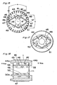
- Fig. 14 is a longitudinal sectional view of the self-starting synchronous motor of a type utilizing permanent magnets according to a first preferred embodiment of the present invention
- Fig. 15 is a cross-sectional view taken along the line A-A' in Fig. 14.
- Fig. 16 is a plan view of an end plate made of a non-magnetizable material and used for protection of the permanent magnets.
- Fig. 17 is an end view of the rotor after the permanent magnets have been inserted and arranged, but before the end plate is fixed to the rotor.
- reference numeral 41 represents a rotor
- reference numeral 42 represents a rotor iron core in the form of a laminated structure of electromagnetic steel plates.
- Reference numeral 43 represents conductor bars molded together with shortcircuit rings 44 positioned on respective ends of the conductor bars by means of an aluminum die casting technique to provide a starter squirrel cage conductor.
- Reference numeral 45 represents permanent magnets each having a width Q.
- Reference numeral 46 represents magnet retaining holes defined in the rotor iron core 42 for accommodating therein the permanent magnets.
- two plate-like permanent magnets 45 of the same polarity are butted end-to-end in a generally V-shaped configuration to form a single rotor magnetic pole and, since four permanent magnets 45e employed in the rotor, two rotor magnetic poles are formed.
- Reference numeral 47 represents a barrier for preventing a shortcircuit of the magnetic fluxes developed between the neighboring permanent magnets of different polarities, which is also filled in position by means of the aluminum die casting.
- Reference numeral 48 represents end plates made of a non-magnetizable material and used to protect the permanent magnets, each being formed with an engagement hole 48a.
- Reference numeral 49 represents axial holes defined in the rotor iron core 42 so as to extend axially thereof, which holes are filled with aluminum 50 that is used during the aluminum die casting to form the starter squirrel cage conductor. The aluminum 50 filling up the axial holes 49 protrudes axially outwardly from the opposite ends of the rotor iron core 42 to thereby define projections 50a as best shown in Fig. 14 .
- the end plates 48 are, after the projections 50a have been passed through the associated engagement holes 48a in the end plates 48, fixed to the opposite end faces of the rotor iron core 42 by crimping or staking the projections 50a to enlarge as shown by broken lines in Fig. 14 .
- Reference numeral 51 represents a bearing hole defined in the rotor iron core 42.
- the amount of the magnetic fluxes of the permanent magnets 45 that can be obtained from the rotor is substantially proportional to the product of the width Q of the permanent magnets 45 times the length of the permanent magnets 45 as measured in the axial direction of the rotor, that is, the area of magnetic poles of the permanent magnets 45.
- the rotor magnetic poles may be equally formed by inserting and arranging permanent magnets, which have not yet been magnetized, in the rotor iron core to complete the rotor and then polarizing the permanent magnets with the use of a magnetizing apparatus.
- the angle ⁇ of end-to-end abutment of the same poles of the permanent magnets 45 is chosen to be larger than the angle ⁇ in the prior art that is 90° as shown in Fig. 25 , and the width Q of each permanent magnet 45 as measured in a direction perpendicular to the longitudinal axis thereof is enlarged to a value larger than the width P in the prior art as shown in Fig. 25 .
- each of the shortcircuit rings 44 employed in the present invention is not round in shape such as used in the prior art, but of a generally rhombic shape, as shown in Fig. 17 , having its outer contour positioned outwardly of the magnet retaining holes 46 and allowing an inner diameter of the ends of the rotor magnetic poles to be greater than that of the center of the rotor magnetic poles.
- each of the shortcircuit rings 44a is not chosen to be round in conformity with the inner diameter at the end of the magnetic poles of the total peripheral rotor is that, if it is so chosen, the equivalent sectional surface area of each shortcircuit ring A as a whole of 44a will become so excessively small as to increase the resistance, resulting in reduction in starting capability of the motor.
- the permanent magnets 45 can have an increased area of surface of the magnetic poles, the amount of the magnetic fluxes of the permanent magnets required by the motor can be obtained.
- FIG. 18 is a longitudinal sectional view of the self-starting synchronous motor of a type utilizing permanent magnets according to the second embodiment of the present invention
- Fig. 19 is an end view as viewed from an S side in Fig. 18 .
- broken lines show the position of magnet retaining holes 46 and single-dotted lines show an outer contour of the end plate 58.
- the width and the angle of end-to-end abutments of the permanent magnets 45 and the inner diametric shape of the shortcircuit ring A of 44a are all similar to those in the previously described first comparative example to the present invention, and the shortcircuit ring B of 44b on the opposite S side has an inner diameter that is round and is so chosen to be small as to allow it to be positioned inwardly of the magnet retaining holes 46.
- the end plate 58 is similarly arranged in abutment with an end face of the rotor iron core 42 on the S side and is of a shape sufficient to encompass the magnet retaining holes 46 and, accordingly, there is no possibility that the die cast aluminum may leak into the magnet retaining holes 46 which would otherwise render it difficult to insert the permanent magnets 45.
- Fig. 20 is a longitudinal sectional view of the self-starting synchronous motor of a type utilizing permanent magnets according to the third embodiment of the present invention
- Fig. 21 is a plan view of one or a plurality of electromagnetic steel plates 59 at one end on the S side of the rotor iron core 2
- Fig. 22 is an end view as viewed from the S side.
- the width and the angle of end-to-end abutments of the permanent magnets 45 and the inner diametric shape of the shortcircuit ring A of 44a are all similar to those in the previously described first embodiment of the present invention.
- the shortcircuit ring C of 44c on the S side has its inner diameter or bore which is round and is so chosen as to be positioned inwardly of the magnet retaining holes 46.
- One or a plurality of electromagnetic steel plates 59 at the end on the S side of the rotor iron core 42 is provided with slots of the same shape and size defined at the same position as the electromagnetic steel plates other than those at the end, but no magnetic retaining hole 46 is provided. Accordingly, even though the inner diameter of the shortcircuit ring C of 44c is small, there is no possibility that the die cast aluminum will leak into the magnet retaining holes 46 to render it to be difficult to insert the permanent magnets.
- FIG. 23 is an end view of the rotor as viewed in a direction conforming to the direction of insertion of permanent magnets 45, showing the rotor after the permanent magnets 45 have been inserted and arranged, but before the end plate is mounted.
- the inner diameter or bore of the shortcircuit ring D of 44d is of a shape conforming to and extending along the magnet retaining holes 46.
- This design permits the permanent magnets 45 to be inserted along a wall surface inside the inner diameter or bore of the shortcircuit ring D of 44d, thereby facilitating a job of insertion of the permanent magnets to thereby increase the ease to assembly.
- FIG. 24 illustrates a transverse sectional view of the self-starting synchronous motor of the type employing the permanent magnets according to the fifth embodiment of the present invention.
- reference numeral 61 represents a stator
- reference numeral 62 represents a stator iron core in the form of a laminate structure of electromagnetic steel plates, which laminate structure has a laminate thickness indicated by Ls.
- Reference numeral 63 represents a stator winding wound around the stator iron core 62.
- the rotor 41 employed therein is substantially identical with that described in connection with the first embodiment with reference to Fig.
- the laminate thickness of the electromagnetic steel plates forming the rotor iron core 42 can advantageously reduced to a value substantially equal to the laminate thickness Ls of the stator iron core.
- the motor of the type utilizing the permanent magnets is generally designed by selecting the axial length of the permanent magnets to be greater than the laminate thickness of the stator iron core so that portions of the magnetic fluxes of the permanent magnets, which emerge outwardly from the opposite ends of the stator iron core, can flow inwardly of the stator iron core from the opposite ends thereof to thereby increase the amount of the magnetic fluxes that runs through the whole of the stator iron core and, for that purpose, the laminate thickness of the rotor iron core is chosen to be greater than the laminate thickness of the stator iron core.
- the design has been employed as hereinabove described to render the laminate thickness Ls of the stator iron core and the laminate thickness LR of the rotor iron core to be substantially equal to each other.
- the number of the electromagnetic steel plates for each of the stator and rotor iron cores that are simultaneously blanked within the same dies is substantially equal for the both and, therefore, production of surplus electromagnetic steel plates can be suppressed to thereby reduce the cost.
- Fig. 26 is a longitudinal sectional view of the rotor used in the synchronous motor according to the fifth comparative example to the present invention.
- reference numeral 71 represents a rotor
- reference numeral 72 represents a rotor iron core
- Reference numeral 72a represents a rotor iron core formed by laminating rotor iron plates E, and one of the rotor iron plates E is shown in Fig. 27 .
- reference numeral 73 represents magnet retaining holes, and when the rotor iron plates E are laminated, the magnet retaining holes 73 are axially aligned with each other as shown in Fig. 26 with the respective permanent magnets 74 subsequently embedded therein.
- Reference numeral 72b1 shown in Fig. 26 represents a rotor iron core formed by laminating rotor iron plates F to an axial end face of the rotor iron core 72a, one of the rotor iron plates F being shown in Fig. 28 in a plan view.
- reference numeral 77 represents magnetic flux shortcircuit preventive holes that are arranged at the same position as the magnet retaining holes 73 in the rotor iron plates E, but have a width U smaller than the width T of the magnet retaining holes 73.
- reference numeral 72c1 represents a rotor iron core made of one or more rotor iron plates E laminated to the axial end face of the rotor iron core 72b1. Also, in Fig.
- reference numeral 76 represents an end plate made of a non-magnetizable material and having a shape sufficient to overlay the magnet retaining holes 73 and the magnetic flux shortcircuit preventive holes 77 so as to prevent debris of the permanent magnets 74, which would be generated at the time the permanent magnets 74 are inserted in and embedded in the magnet retaining holes 73, from flowing outwardly and also to prevent external foreign matter from being trapped into the magnet retaining holes 73.
- an axial end face 79 of each of the permanent magnets 79 is held in engagement with an outer peripheral edge 78 of the respective magnetic flux shortcircuit preventive hole 77 on an abutment face of the rotor iron core 72b1 that is in engagement with the rotor iron cores 72a and, accordingly, magnetic fluxes 80 leaking between N and S poles at the respective opposite ends of the permanent magnets 74 run from the rotor iron cores 72a back to the permanent magnets 74 through the rotor iron core 72b1, then across the magnetic flux shortcircuit preventive holes 77 and finally through the rotor iron cores 72b1 and 72a.
- the leaking magnetic fluxes 80b1 runs from the rotor iron cores 72a back to the permanent magnets 74 through the rotor iron core 72b1, then through the rotor iron core 72c1, across the magnet retaining holes 73, again through the rotor iron core 72c1, the rotor iron core 72b1 and finally through the rotor iron core 72a.
- the rotor iron core 72b1 is made up of a single rotor iron plate or a plurality of rotor iron plates F in a number as small as possible so long as the permanent magnets can be positioned, a magnetic circuit through which the leaking magnetic fluxes 80a1 run can have a magnetic resistance of a magnitude sufficient to minimize the leaking magnetic fluxes 80a1.
- the width T of the magnet retaining holes 73 in the rotor iron plate E forming the rotor iron core 72c1 is so larger than the width U of the magnetic flux shortcircuit preventive hole 77 in the rotor iron plate F that, as compared with the case in which the rotor iron core 72c1 is prepared from the rotor iron plate F, the magnetic circuit through which the leaking magnetic fluxes 80b1 run can have a magnetic resistance of a magnitude sufficient to minimize the leaking magnetic fluxes 80b1. Therefore, the motor characteristic can be increased.
- the permanent magnets 74 attracts and is therefore held in engagement with the outer peripheral edge 78 of the magnetic flux shortcircuit preventive hole 77 in the rotor iron core 72b1, the permanent magnets 74 can be accurately positioned with respect to the axial direction thereof only by means of the rotor iron cores 72 with no holder employed, thereby reducing the cost for assembly and component parts.
- the number of the rotor iron plates F laminated is so chosen that a point intermediate of the axial length of the rotor iron cores 72 can match with a point intermediate of the axial length of the permanent magnets 74, and this equally applies to any one of the comparative examples that follow.
- the permanent magnets are made of a rare earth metal of, for example, Nd-Fe-B system
- the magnet made of the rare earth metal of the Nd-Fe-B system is known to exhibit a high residual magnetic flux density, the volume of the rotor and the motor as a whole can advantageously be reduced.
- the permanent magnets has been employed in the form of a generally plate-like configuration, but the present invention may not be limited thereto and can be equally applied to the rotor employing the permanent magnets of any suitable shape such as, for example, an arcuate shape.
- FIG. 29 is a longitudinal sectional view of the rotor used in the synchronous motor
- Fig. 30 is a plan view of the rotor iron plate G.
- reference numeral 72d1 represents a rotor iron core comprising a rotor iron core 72a having its axial end face to which rotor iron plates G are laminated. Since the rotor iron plates G have no magnet retaining hole defined therein, lamination of the rotor iron plates G to the axial end face of the rotor iron core 72a results closure of the magnet retaining holes 73.
- the permanent magnets 74 Since the axial end face 81 of the permanent magnets 74 is held in engagement with an abutment face of the rotor iron core 72d1 that is held in engagement with the rotor iron core 72a, magnetic fluxes 80c1 leaking from the axial end of the permanent magnets 74 runs from the rotor iron core 72a back to the permanent magnets 74 through the rotor iron core 72d1 and then through the rotor iron core 72a. Also, since the permanent magnets 74 attract and are therefore held in engagement with the axial end face 82 of the rotor iron core 72d1, the permanent magnets 74 can be accurately positioned with respect to the axial direction thereof with no need to use any holder, thereby reducing the cost for assembly and component parts.
- the magnet retaining holes 73 in the rotor iron core 72a are closed at one end by the rotor iron core 72d1, positioning of a single end plate 76 at the opposite end is sufficient to close the opposite ends of the magnet retaining holes 73. While in the previously described fifth comparative example to the present invention, two end plates 76 are required, the sixth comparative example requires the only end plate 6 and, therefore, the cost for assembly and component parts can further be reduced.
- the rotor iron plate E and the rotor iron plate G can easily manufactured by controlling loading and unloading of blanking dies, that are used to form the magnet retaining hole 73, during a blanking process. Therefore, no blanking dies that are required in the previously described fifth comparative example to the present invention to form the magnetic flux shortcircuit preventive hole 77 in the rotor iron plate F is needed, making it possible to simplify the structure of the dies themselves.
- Fig. 31 illustrates a longitudinal sectional view of the rotor used in the synchronous motor according to a seventh comparative example to the present invention.
- An axial end face of the rotor iron core 72d2 opposite to that with which the axial end face 81 of the permanent magnets 74 are held in engagement is provided with a rotor iron core 72c2 of a laminated structure including rotor iron plates E.
- magnetic fluxes 80c2 leaking at the axial end of the permanent magnet 74 run from the rotor iron core 72a back to the permanent magnet 74 through the rotor iron core 72d2 and then through the rotor iron core 72a.
- the leaking magnetic fluxes 80b2 runs from the rotor iron cores 72a back to the permanent magnet 74 through the rotor iron core 72d2, then through the rotor iron core 72c2, across the magnet retaining holes 73, again through the rotor iron core 72c2, the rotor iron core 72d2 and finally through the rotor iron core 72a.
- the magnetic circuit through which the leaking magnetic fluxes 80b2 run in this seventh comparative example has a relatively high magnetic resistance and, therefore, the sum of the leaking magnetic fluxes 80c2 and 80b2 in this seventh comparative example is smaller relative to the leaking magnetic fluxes 80c1 in the previously described sixth comparative example. Accordingly, since the leaking magnetic fluxes can be reduced as compared with that in the previously described comparative example, the motor characteristic can be increased.
- FIG. 32 illustrates a longitudinal sectional view of the rotor used in the synchronous motor according to the eighth comparative example to the present invention.
- reference numeral 83 represents a rotor
- reference numeral 84 represents a rotor iron core.
- Reference numeral 84a represents a rotor iron core made up of a laminate of rotor iron plates H.
- Reference numeral 84b represents a rotor iron core made up of a laminate of rotor iron plates I, one of which is shown in Fig. 34 in a plan view.
- Fig. 33 illustrates a plan view of the rotor iron plate H.
- reference numeral 85 represents a plurality of slots for accommodating conductor bars 86a of the starter squirrel cage conductor
- reference numeral 73 represents magnet retaining holes.
- reference numeral 87 represents a plurality of slots for accommodating the conductor bars 86a of the starter squirrel cage conductor shown in Fig. 32 , which slots 86a are of the same shape as the slots 85 in the rotor iron plate H and are positioned at the same position as the slots 85 in the rotor iron plate H.
- Reference numeral 77 represents magnetic flux shortcircuit preventive holes that are positioned at the same position as the magnet retaining holes 73 in the rotor iron plate H of Fig. 33 , but have a width U smaller than the width T of the magnet retaining holes 73.
- reference numeral 84c represents a rotor iron core made up of one rotor iron plate E or a laminate of rotor iron plates E.
- the conductor bars 86a and shortcircuit rings 86b are formed integrally together to define the starter squirrel cage conductor.
- the starter squirrel cage conductor By arranging the starter squirrel cage conductor in the rotor 83, the self-starting synchronous motor of the type employing the permanent magnets can be obtained which operates as an inductor motor at the time of starting thereof and as a synchronous motor entrained by a synchronous speed upon arrival at the synchronous speed.
- the rotor iron core 84b having the magnetic flux shortcircuit preventive holes 77 defined therein are employed and the rotor iron plates E are laminated, the leaking magnetic fluxes between the N and S poles at the axially opposite ends of the permanent magnets 74 can be reduced, thereby increasing the motor characteristic.
- the permanent magnets 74 can be accurately positioned only by the rotor iron core 84 with no need to employ any holder and, therefore, the cost for assembly and component parts can be reduced advantageously.
- FIG. 35 illustrates a longitudinal sectional view of the rotor used in the synchronous motor according to the ninth comparative example to of the present invention
- Fig. 36 illustrates a plan view of an electromagnetic steel plate J positioned inwardly of opposite axial ends of the rotor
- iron core illustrates a plan view of an electromagnetic steel plate K positioned at the opposite axial ends of the rotor iron core.
- reference numeral 91 represents a rotor
- reference numeral 92 represents a rotor iron core of a laminated structure including the electromagnetic steel plates J 110 and the electromagnetic steel plates K 111.
- the electromagnetic steel plates J 110 and K 111 are formed with respective conductor bar slots 112 of the same size, respective barrier slots 113 of the same size for preventing the magnetic flux shortcircuit, respective holes 99 of the same size and respective bearing holes 114 of the same size, which are aligned with each other.
- Reference numerals 96b and 96a represent magnet retaining holes defined at the same position, wherein respective hole widths R and S as measured in a direction radially thereof are so chosen as to satisfy the relationship R ⁇ S.
- Reference numeral 93 represents conductor bars made of aluminum and filled in the respective slots 112.
- the conductor bars 93 are integrally molded together with the shortcircuit rings 94 at the axially opposite ends of the rotor iron core 92 by means of any known aluminum die casting technique to thereby form the starter squirrel cage conductor.
- Reference numeral 95 represents permanent magnets, every two of which are, after the aluminum die casting, held in end-to-end abutment to represent a generally V-shaped configuration and are then inserted and arranged in the magnet retaining holes 96 and 96a so that the two pairs of the permanent magnets 95 can define two magnetic poles.
- Reference numeral 98 represents a non-magnetizable end plate for protection of the permanent magnets 95, which end plate has an engagement hole 98a defined therein.
- Reference numeral 99 represents an axial hole defined in the rotor iron core 92 so as to extend axially thereof, in which hole is filled aluminum 100 that is injected during the aluminum die casting to form the starter squirrel cage conductor.
- the aluminum 100 filled in the axial hole 99 has projections 100a protruding outwardly from the axially opposite ends of the rotor iron core 92.
- the end plates 98 are, after the engagement holes 98a have received therein the projections 100a, fixed to the respective axial end faces of the rotor iron core 92 by staking or crimping the projections 100a to enlarge as shown by broken lines.
- Reference numerals 101 and 114 represents respective bearing holes.
- the rotor magnetic poles may be equally formed by inserting and arranging permanent magnets, which have not yet been magnetized, in the rotor iron core to complete the rotor and then polarizing the permanent magnets with the use of a magnetizing apparatus.
- the outer diameter of the magnet retaining holes 96a in the electromagnetic steel plates K 111 at each axial end of the rotor iron core 92 deforms and contracts under the influence of a force of shrinkage acting in an inner radial direction.
- the hole width S of the magnet retaining holes 96a is sufficiently larger than the hole width R of the magnet retaining hole 96 in the electromagnetic steel plates J that are small of the shrinkage force of the shortcircuit rings 94, there is no possibility that as a result of reduction in gap between the permanent magnets 95b and the magnet retaining holes 96a that is brought about by deformation and shrinkage insertion of the permanent magnets 95 into the respective magnet retaining holes 96a is difficult to achieve.
- the hole width S of the magnet retaining holes 98a is so chosen as to be slightly greater than R by a quantity that a side adjacent an outer diameter of the hole width S when receiving the shrinkage force of the shortcircuit ring 94 can line up with a side adjacent an outer diameter of the hole width R of the magnet retaining hole 96, and accordingly, a possibility can be avoided which would, as a result of reduction of the coefficient of permeance of the magnetic circuit can be lowered, the motor characteristic may correspondingly decrease.
- the self-starting synchronous motor of the type employing the permanent magnets according to the ninth comparative example is advantageous in that the permanent magnets 5 can be easily inserted subsequent to the aluminum die casting and that a high-performance motor characteristic can be maintained.
- FIG. 38 is a longitudinal sectional view of the rotor used in the self-starting synchronous motor of the type employing the permanent magnets according to the tenth comparative example to the present invention
- Fig. 39 is a plan view of the electromagnetic steel plate L at one end face of the rotor iron core 92 of Fig. 38 .
- one or a plurality of electromagnetic steel plates L 120 at one end of the rotor iron core on the P side have no magnet retaining hole defined therein.
- the electromagnetic steel plates on the axially opposite ends of the rotor iron core 92 are laminated with the same electromagnetic steel plates K 111 as those shown in Fig. 37 in connection with the ninth comparative example and the electromagnetic steel plates J 110 are laminated inwardly of the opposite ends. Since the axial end face of the permanent magnets abuts against the electromagnetic steel plate L, the number of the electromagnetic steel plates L laminated is so chosen that respective axial centers of the rotor iron core and the permanent magnets can match with each other.
- the hole width S of the magnet retaining holes 96a in the electromagnetic steel plates K 111 on the axially opposite ends of the rotor iron core 2 is sufficiently greater than the hole width R of the magnet retaining holes 96 in the inside electromagnetic steel plates J 110, even though a radially inwardly shrinking deformation occurs under the influence of the radially inwardly acting shrinkage force from the shortcircuit rings 94 subsequent to the aluminum die casting, the permanent magnets 95 can be carried out without being disturbed and, since as is the case with the first comparative example to the present invention, the gaps between the permanent magnets 95b and the magnet retaining holes in the rotor iron core 92 are properly maintained, a high-performance motor characteristic can be maintained.
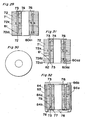
- Fig. 40 is a longitudinal sectional view of the rotor employed in the self-starting permanent magnet synchronous motor according to the eleventh comparative example.
- one or a plurality of electromagnetic steel plates L 120 shown in Fig. 40 and having no magnet retaining holes defined therein are laminated to one end of the rotor iron core 92 on the P side, and one or a plurality of electromagnetic steel plates K 111 having the magnet retaining holes of a relatively great hole width are laminated to the opposite end of the rotor iron core 92 on the Q side.
- the shrinkage stress of the shortcircuit ring 94 has no concern therewith and, therefore, the permanent magnets 95 can easily be inserted in the rotor iron core 92 if the electromagnetic steel plates K 111 having the magnet retaining holes 96 of a relatively great hole width are arranged only on the Q side. Accordingly, the rotor iron core 92 can be assembled with a minimized combination of the electromagnetic steel plates J 110, K 111 and L 120, thereby facilitating the manufacture thereof and also maintaining a high-performance motor characteristic.
- Fig. 41 is a longitudinal sectional view of the rotor employed in the self-starting permanent magnet synchronous motor according to the twelfth comparative example and Fig. 42 is an end view of the synchronous motor viewed from the P side in Fig. 41 .
- the basic structure of the rotor in the twelfth comparative example is substantially similar to that described in connection with any of the tenth and eleventh comparative examples.
- the shortcircuit ring 94a having a reduced inner diameter is formed on an outer end face of the electromagnetic steel plates L 120 shown in Fig. 39 and having no magnet retaining hole defined therein on the P side, by means of the aluminum die casting.
- the inner diameter of the shortcircuit ring 94a is such that it can be enclosed inwardly of the whole of the magnet retaining holes 96 and 96a defined respectively in the electromagnetic steel plates j and K as shown by the broken lines, or partly inwardly thereof although not shown. Since the electromagnetic steel plates L 120 have no magnet retaining hole such as identified by 96, there is no possibility that during the aluminum die casting aluminum may penetrate into the magnet retaining holes 96.
- the shortcircuit ring 94a can have an increased cross-sectional surface area to thereby reduce a secondary resistance of the rotor, the rotational speed of the motor at the time of a maximum torque en route the synchronous speed and the at the time of the maximum torque can increase to facilitate a synchronous entanglement, thereby increasing the starting performance of the motor.
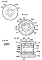
- FIG. 43 shows a plan view of an electromagnetic steel plate M for the rotor of the self-starting permanent magnet synchronous motor according to the thirteenth comparative example.
- reference numeral 131 represents entwining portions for lamination of the electromagnetic steel plates. As shown in Fig. 43 , when the electromagnetic steel plates are blanked one by one, press projections are formed and are laminated together while sequentially entwined therewith to thereby form the rotor iron core. In such case, the entwining portions 131 are defined at respective locations outwardly of the magnet retaining holes 132.
- Reference numeral 132a represents an enlarged portion in which the hole width of a portion of each magnet retaining hole 132 adjacent the corresponding entwining portion 131 is enlarged radially outwardly by a required quantity V towards such corresponding entwining portion 131.
- Reference numeral 133 represents a pincer portion of the electromagnetic steel plate M 130 bound between the corresponding entwining portion 131 and the enlarged portion 132a of each magnet retaining hole.
- the enlarged portion 132a in which the hole width of each magnet retaining hole adjacent the corresponding entwining portion 131 is increased by the quantity V towards the entwining portion 131, even though the corresponding pincer portion 133 is deformed to protrude inwardly of the associated magnet retaining hole 132 under the influence of press stresses during formation of the corresponding entwining portion by the use of a press work, the deformation can be accommodated within the enlarged quantity V and, therefore, the permanent magnet can easily be inserted without being disturbed.
- the enlarged portion 132a has a length W that is small in correspondence with the length of the adjacent entwining portion 131 and, also, the specific value of the quantity V is small and will decrease in response to inward deformation of the pincer portion 133, the gap with the permanent magnet is very minute and the coefficient of permeance of the magnetic circuit will not decrease substantially, thereby securing a high-performance motor characteristic.
- each of the permanent magnets is made of a rare earth metal of, for example, Nd-Fe-B system, a high magnetic force can be obtained and, therefore, the rotor and the motor as a whole can advantageously be manufactured in a compact size and lightweight.
- the single pole has been formed by abutting two plate-like permanent magnets of the same polarity in end-to-end fashion
- the present invention may not be limited thereto and the single pole may be formed by the use of a single permanent magnet or three or more plate-like permanent magnets of the same polarity.
- the permanent magnets have been employed in the plate-like form, the present invention is not limited thereto and the present invention is equally applicable to the rotor employing permanent magnets of, for example, an arcuate shape or any other suitable shape.
- FIG. 45 illustrates a longitudinal sectional view of the rotor used in the self-starting synchronous motor of the type employing the permanent magnets according to the fourteenth comparative example
- Fig. 46 is a transverse sectional view of the rotor
- Fig. 47 is a plan view of an end plate.
- reference numeral 141 represents a rotor
- reference numeral 142 represents a rotor iron core made of a laminate of electromagnetic steel plates.
- Reference numeral 143 represents conductor bars which are molded integrally together with shortcircuit rings 144, positioned at axially opposite ends of the rotor iron core 142, by the use of the aluminum die casting technique to form a starter squirrel cage conductor.
- Reference numeral 145 represents permanent magnets, every two of which are held in end-to-end abutment to represent a generally V-shaped configuration and are so arranged that the two pairs of the permanent magnets 145 can define two magnetic poles.
- Reference numeral 147 represents shortcircuit preventive barriers for preventing shortcircuit of the magnetic fluxes between the permanent magnets of the different polarities and filled up with aluminum die cast.
- Reference numeral 148 represents an end plate made of a non-magnetizable material and used of protection of the permanent magnets 145, in which engagement holes 148a are defined.
- Reference numeral 149 represents an axial hole defined in the rotor iron core 142 so as to extend axially thereof, in which hole is filled aluminum 150 that is injected during the aluminum die casting to form the starter squirrel cage conductor.
- the aluminum 150 filled in the axial hole 149 has projections 150a protruding outwardly from the axially opposite ends of the rotor iron core 142.
- the end plates 148 are, after the engagement holes 148a have received therein the projections 150a, fixed to the respective axial end faces of the rotor iron core 142 by staking or crimping the projections 150a to enlarge as shown by broken lines.
- the projections 150a used to secure the end plates 148 to the axially opposite ends of the rotor 141 are formed simultaneously with formation of the starter squirrel cage conductor by the use of the aluminum die casting technique and since the end plates 148 can be firmly secured to the axially opposite end faces of the rotor iron core 142 merely by staking or crimping the projections 150a, the cost for the material and the number of assembling steps can be considerably reduced as compared with the prior art in which bolts are employed, thereby making it possible to provide an inexpensive self-stating synchronous motor of the kind employing the permanent magnets.
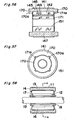
- Fig. 48 is a longitudinal sectional view of the self-starting permanent magnet synchronous motor
- Fig. 49 is a plan view of the end plate used in the synchronous motor shown in Fig. 48
- Fig. 50 is a cross-sectional view taken along the line C-C' in Fig. 49 .
- the shortcircuit rings 144a are formed so as to cover the end plates 152.
- the end plate 152 is integrated with the axially end face of the rotor iron core 152 by means of the aluminum die casting used to form the starter squirrel cage conductor.
- the end plate 152 is formed with two projections 152a each having a respective hole 152 defined therein so as to extend completely across the thickness thereof.
- the end plate 152 Prior to the aluminum die casting, the end plate 152 is secured to the corresponding end face of the rotor iron core 142 with the projections 152a protruding through the holes 149 to thereby position the respective end plate 152 so that the end plate 152 will not displace during the aluminum die casting in which a high pressure may act on the end plate 152 to allow the end plate 152 to be firmly connected to the associated end face of the rotor iron core 142 without being displaced in position.
- the end plate 148, the end plate 148 is, as is the case with that in the previously described fourteenth comparative example, fixed to the end face of the rotor iron core 142 by staking or crimping the projections 150a after the end plate 148 has been engaged with the projections 150a for fixing the end plate.
- end plate 152 is integrally connected with the rotor iron core 142 by means of the aluminum die casting, a job of securing the end plate by staking or crimping the projections 150a has to be performed only in association with the end plate 148 and, therefore, as compared with the previously described fourteenth comparative example, the number of assembling steps can further be reduced.
- FIG. 51 illustrates a longitudinal sectional view of the rotor used in the self-starting synchronous motor
- Fig. 52 is a plan view of an electromagnetic steel plate positioned at an axial end of the rotor iron core used in the rotor of Fig. 51 .
- the electromagnetic steel plate 160 positioned at the axial end of the rotor iron core 142 having conductor bar slots 161, barrier holes 162 for preventing the magnetic flux shortcircuit, holes 149 and a bearing hole 150 all defined therein is of the same shape as that used at a different position, but no magnet retaining hole 146 defined therein.
- this electromagnetic steel plate 160 is manufactured by blanking with the use of the same core dies as used for the other electromagnetic steel plates, since mold pieces used to form the magnet retaining holes 146 in the electromagnetic steel plate 160 by the use of a blanking technique are of a type that can be removably mounted on a die assembly, it is easy to avoid formation of the magnet retaining holes 146 in the electromagnetic steel plate 160 at the time the latter is blanked off from a metal sheet. Accordingly, the rotor iron core 142 can be integrally formed together with the electromagnetic steel plate 160 and, if this is aluminum die cast, the starter squirrel cage conductor can be formed.
- the end plate on the other end is needed and, as is the case with the previously described fifteenth comparative example, a job of securing the end plate by staking or crimping the projections 150a has to be performed only in association with the end plate 148 and, therefore, as compared with the previously described fourteenth comparative example, the number of assembling steps can further be reduced.
- Fig. 53 is a plan view of the electromagnetic steel plate at the axial end of the rotor iron core and Fig. 54 is a fragmentary enlarged view showing a portion of the rotor 141.
- reference numeral 162 represents an electromagnetic steel plate disposed at an axial end of the rotor iron core 141
- reference numeral 164 represents a projection protruding inwardly of the permanent magnets 154 at a location where the electromagnetic steel plate 163 engages the permanent magnets 145. Accordingly, the permanent magnets 145 are axially positioned with the projection 164 in the electromagnetic steel plate 163 brought into engagement therewith.
- Fig. 55 is a longitudinal sectional view of the complete rotor used in the self-starting synchronous motor according to this example
- Fig. 56 is a longitudinal sectional view of the rotor before the end plates are fixed
- Fig. 57 is an end view of the rotor shown in Fig. 56 .
- the end plate 171 has its outer periphery formed with radial projections 171 a and, on the other hand, the shortcircuit ring 170 formed by the aluminum die casting has an inner periphery formed with a radial recesses 170a complemental in shape to the radial projections 171 a in the end plate 171.
- peripheral portions of the radial recesses 170a in the shortcircuit ring 170 are axially pressed to deform as shown by 170b in Fig. 55 to thereby fix the end plate 171 to the rotor iron core 2.
- fixing of the end plate 171 can easily be accomplished merely by pressing the radial recesses 170a in the shortcircuit ring 170 to deform in the manner described above and, therefore, the number of assembling steps can advantageously be reduced.
- the permanent magnets is made of a rare earth metal of, for example, Nd-Fe-B system, a strong magnetic force can be obtained and, therefore, the rotor as well as the motor as a whole can be manufactured in a compact size and lightweight.
- the rotor has been shown having two magnetic poles, it may have four or more magnetic poles.
- the single pole has been formed by abutting two plate-like permanent magnets of the same polarity in end-to-end fashion, the present invention may not be limited thereto and the single pole may be formed by the use of a single permanent magnet or three or more plate-like permanent magnets of the same polarity.
- the permanent magnets have been employed in the plate-like form, the present invention is not limited thereto and the present invention is equally applicable to the rotor employing permanent magnets of, for example, an arcuate shape or any other suitable shape.
- FIG. 60 illustrates a longitudinal sectional view of the rotor used in the self-starting synchronous motor according to this example
- Fig. 61 is a transverse sectional view of the rotor shown in Fig. 60
- Fig. 62 is a fragmentary enlarged view showing an encircled portion indicated by 196 in Fig. 61 .
- reference numeral 181 represents a rotor
- reference numeral 182 represents a rotor iron core made of a laminate of electromagnetic steel plates.
- Reference numeral 183 represents conductor bars that are formed integrally together with shortcircuit rings 184, positioned at axially opposite ends of the rotor iron core 182, by the use of an aluminum die casting technique to form a starter squirrel cage conductor.
- Reference numeral 185 represents permanent magnets accommodated within magnet retaining holes 186, with each pair of plate-like permanent magnets 185 of the same polarity butted end-to-end in a generally V-shaped configuration to form a single rotor magnetic pole. Since four permanent magnets 185 are employed in the rotor, two rotor magnetic poles are formed and, thus, the rotor as a whole has two magnetic poles.
- a bridge portion indicated by 187 is so shaped as to have its width including a narrow portion 187a and a large-width portion 187b increasing in width in a direction radially outwardly from the narrow portion 187a. Shortcircuit of the magnetic fluxes between front and rear, opposite poles of the permanent magnets 185 can advantageously be prevented since magnetic saturation takes place at the narrow portion 187a.
- Reference numeral 189 represents barrier slots for prevention of the magnetic flux shortcircuit that are defined between the neighboring permanent magnets 185 of the different polarities, which slots are filled up with aluminum injected during the aluminum die casting.
- a bridge portion 191 of the rotor iron core 182 between each barrier slot 189 and each magnet retaining hole 186 is so shaped as to have a small width, and at this bridge portion 191, magnetic saturation takes place to prevent the magnetic fluxes emanating from the opposite poles of the permanent magnets 185 from shortcircuiting.
- an air space 192 is formed between an end face of each permanent magnet 185 and the adjacent bridge portion 191 to prevent the magnetic fluxes from the opposite poles within the end faces of the permanent magnets 185 from shortcircuiting.
- Reference numeral 193 represents an end plate made of a non-magnetizable material for protecting the permanent magnets 185. This end plate 193 is riveted to axially opposite end faces of the rotor iron core 182 by means of rivet pins 194.
- Reference numeral 195 represents a bearing hole defined in the rotor.
- the rotor 181 can be assembled by embedding the permanent magnets 185 in the respective magnet retaining holes 186 after the starter squirrel cage conductor has been formed by the aluminum die casting in the rotor iron core 182 made of a laminate of the electromagnetic steel plates, and subsequently riveting the end plate 193 to each of the axially opposite end faces of the rotor iron core 182 by means of the rivet pins 194.
- the rotor iron core 182 While after the aluminum die casting the shortcircuit rings will shrink in a radial direction during cooling of the aluminum, the rotor iron core 182 is also affected by a radially inwardly acting shrinkage stress. However, since the bridge portion 191 of the rotor iron core 182 is provided on each sides of each of the barrier slots 189 at a location adjacent the respective barrier slot 198 as shown in Fig. 58 , a strength against the shrinkage stress is so high that circumferential shrinkage strains of an outer diameter of the rotor iron core 182 can be small.
- the bridge portion 187 is provided only at one location, strain acting in an inner diametric direction of the rotor iron core 182 at this portion is large.
- the length in a radial direction of the narrow portion 187a of the bridge portion 187 for prevention of the magnetic flux shortcircuit by magnetic saturation is reduced and, on the other hand, the large-width portion 187b is provided next to the narrow portion 187a, wherefore the strength against the radial shrinkage stress of the bridge portion 187 as a whole is made strong to prevent the strain from occurring in an inner diametric direction of the rotor iron core 182 at a location adjacent the bridge portion 187.
- the rotor iron core 182 can have an outer diameter of a shape substantially similar to the right round shape and, therefore, if the outer diameter thereof is so chosen at the time of blanking the electromagnetic steel plates of the rotor iron core 182 that a gap between the outer diameter thereof and an inner diameter of the rotor iron core can be of a predetermined dimension, a step of grinding or milling the outer diameter of the rotor iron core after the aluminum die casting to provide the gap of the predetermined dimension can be dispensed with.
- the single pole has been formed by abutting two plate-like permanent magnets of the same polarity in end-to-end fashion
- the present invention may not be limited thereto and the single pole may be formed by the use of a single permanent magnet or three or more plate-like permanent magnets of the same polarity.
- the permanent magnets have been employed in the plate-like form, the present invention is not limited thereto and the present invention is equally applicable to the rotor employing permanent magnets of, for example, an arcuate shape or any other suitable shape.
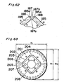
- Fig. 63 illustrates a plan view of an electromagnetic steel plate used to form the rotor in the self-starting synchronous motor according to this example.
- reference numeral 51 represents an electromagnetic steel plate, a plurality of which are laminated together to form the rotor iron core. After the rotor iron core has been so formed, the rotor iron core is subjected to the aluminum die casting to form the starter squirrel cage conductor in the rotor iron core.
- Reference numeral 203 represents magnet retaining holes; reference numeral 204 represents a bridge portion F for each pair of the permanent magnets; reference numeral 205 represents barrier slots for prevention of shortcircuit of the magnetic fluxes; reference numeral 206 represents a bridge portion; reference numeral 207 represents rivet holes through which rivets are passed to secure the end plate to each axial end face of the rotor core; and reference numeral 208 represents a bearing hole.
- the permanent magnets to be inserted after the aluminum die casting are shown by double-dotted lines and the rotor has two rotor magnetic poles formed therein.
- the electromagnetic steel plate 201 has an outer diameter that is set to an outer diameter R1 sufficient to allow a gap between the rotor and the inner diameter of the stator iron core at one end of the rotor to satisfy a predetermined dimension, which outer diameter R1 progressively increases towards a center point of the rotor magnetic pole so that the outer diameter R2 of the center portion of the rotor magnetic poles can be greater than the outer diameter R1.
- the shortcircuit rings (not shown) formed on the axially opposite end faces of the rotor iron core of the starter squirrel cage conductor undergo a shrinkage in a radial direction as they are cooled, accompanied by a radial shrinkage of the outer diameter of the rotor iron core under the influence of a shrinkage force of the shortcircuit rings.
- the strength is so high against the shrinkage stress in the inner diametric direction that the outer diameter R1 of the rotor iron core will not vary virtually.
- the bridge portion 264 is defined only at one location, the strength is so low that the outer diameter R2 of the rotor iron core will shrink in a radial direction under the influence of the shrinkage stress.
- the dimension of the outer diameter R2 is chosen to be R1 after shrinkage, the outer diameter of the rotor iron core as a whole can be maintained at a substantially round shape.
- the single pole has been formed by abutting two plate-like permanent magnets of the same polarity in end-to-end fashion
- the present invention may not be limited thereto and the single pole may be formed by the use of a single permanent magnet or three or more plate-like permanent magnets of the same polarity.
- the outer diameter of the rotor iron core after the aluminum die casting attains a shape substantially similar to the right round shape, and since the gap between it and the inner diameter of the stator iron core can be formed by pre-blanking with the use of dies, there is no need to grind or mill the outer diameter of the rotor iron core and, therefore, the number of assembling steps can be reduced. Also, since the aluminum die casting is carried out while the permanent magnets and the end plates have not yet been fitted, the job can be easily performed with no defect parts occurring and, in view of those cumulative effect, the productivity can be increased.
Landscapes
- Engineering & Computer Science (AREA)
- Power Engineering (AREA)
- Permanent Magnet Type Synchronous Machine (AREA)
- Permanent Field Magnets Of Synchronous Machinery (AREA)
Claims (5)
- Synchronmotor, der umfasst:einen Stator (61), der einen Statoreisenkern (62) einschließt, um den zweipolige Wicklungen (63) gewickelt sind, wobei der besagte Statoreisenkern eine innere zylindrische Oberfläche aufweist;einen Läufer (41), der einen Läufereisenkern (42) einschließt und rotierend untergebracht ist, indessen er der inneren zylindrischen Oberfläche des Statoreisenkerns gegenüberliegt, wobei der besagte Läufer eine Vielheit von Stromschienen (43), die angrenzend an einen Außenumfang des Läufereisenkerns positioniert sind und Kurzschlussringe (44) einschließt, die an axial gegenüberliegenden Enden des Läufereisenkerns positioniert sind, wobei die besagten Leiterschienen und Kurzschlussringe mittels eines Aluminiumdruckgussteils integral zusammen gemoldet sind, um einen Start-Käfigläufer-Leiter zu bilden, wobei der besagte Läufer eine Vielheit von Magnethalteschlitzen (46) aufweist, die darin an einer Stelle auf einer Innenseite der Leiterschienen definiert sind;
undDauermagneten (45), die innerhalb der Magnethalteschlitze im Läufer eingebettet sind und zwei Magnetpole verschiedener Polaritäten definieren;dadurch gekennzeichnet, dass jeder der Magnetpole aus zwei Magneten entsprechender Polarität besteht, die stumpf aneinanderstoßend in einer V-förmigen Konfiguration mit einem Winkel (β) dazwischen angeordnet sind;der Stoßwinkel größer als 90° ist und die zwei Magnetpole derart angeordnet sind, dass eine erste radiale Abmessung (a) zwischen den distalen Enden der stumpf aneinanderstoßenden Magneten größer als eine zweite radiale Abmessung (b) zwischen den jeweiligen Stoßpositionen der zwei Magnetpole ist; undwobei die besagten Kurzschlussringe eine Öffnung von generell rhombischer Form aufweisen, wobei die Magnethalteschlitze radial innerhalb der Öffnung positioniert sind. - Synchronmotor wie in Anspruch 1 beansprucht, wobei die Öffnung eines ersten Kurzschlussrings (44) auf der Seite des Synchronmotors von der die Dauermagneten (45) eingeschoben werden, die Magnethalteschlitze (46) im Läufereisenkern (42) radial einschließt;
wobei die innere diametrische Abmessung des ersten Kurzschlussrings, angrenzend an ein distales Ende eines Magnetpols, größer als die innere diametrische Abmessung davon angrenzend an die Stoßposition eines Magnetpols ist;
wobei die ganzen oder ein Teil der Magnethalteschlitze radial außerhalb der Öffnung der anderen der Kurzschlussringe liegen; und
weiter eine Endplatte (58) umfasst, die aus einer nichtmagnetisierbaren Platte hergestellt und zwischen solch einem anderen Kurzschlussring und dem Läufereisenkern positioniert ist, um die Magnethalteschlitze abzudecken. - Synchronmotor wie in Anspruch 1 beansprucht, wobei die Öffnung eines ersten Kurzschlussrings (44) auf der Seite des Synchronmotors von der die Dauermagneten (45) eingeschoben werden, die Magnethalteschlitze (46) im Läufereisenkern radial einschließt;
wobei die innere diametrische Abmessung des Kurzschlussrings, angrenzend an ein distales Ende eines Magnetpols, größer als die innere diametrische Abmessung davon angrenzend an die Stoßposition eines Magnetpols ist; und
wobei die ganzen oder ein Teil der Magnethalteschlitze radial außerhalb der Öffnung der anderen der Kurzschlussringe liegen; und
weiter eine oder eine Vielheit von elektromagnetischen Stahlplatten (59) des Läufereisenkerns angrenzend an den anderen Kurzschlussring umfasst, die nicht mit den Magnethalteschlitzen gebildet ist, oder sind. - Synchronmotor wie in Anspruch 1 beansprucht, wobei die Öffnung des Kurzschlussrings (44) auf der Seite des Synchronmotors von der die Dauermagneten (45) eingeschoben werden, einer Form ist, die Magnethalteschlitzen (46) im Läufereisenkern (42) entspricht.
- Synchronmotor wie in Anspruch 1 beansprucht, wobei der Statoreisenkern (62) aus einem Statorblechpaket elektromagnetischer Stahlplatten zusammengesetzt ist und der Läufereisenkern (42) ebenso aus einem Läuferblechpaket elektromagnetischer Stahlplatten zusammengesetzt ist, wobei das besagte Statorblechpaket eine Dicke (Ls) aufweist, die ca. gleich der Dicke (Lr) des Läuferblechpakets ist.
Priority Applications (4)
| Application Number | Priority Date | Filing Date | Title |
|---|---|---|---|
| EP10179955A EP2276147A1 (de) | 1999-07-16 | 2000-07-13 | Synchronmotor mit Dauermagneten |
| EP10179930A EP2276155A1 (de) | 1999-07-16 | 2000-07-13 | Synchronmotor mit Dauermagneten |
| EP10179927A EP2276154A1 (de) | 1999-07-16 | 2000-07-13 | Synchronmotor mit Dauermagneten |
| EP10179950A EP2276146A1 (de) | 1999-07-16 | 2000-07-13 | Synchronmotor mit Dauermagneten |
Applications Claiming Priority (13)
| Application Number | Priority Date | Filing Date | Title |
|---|---|---|---|
| JP20308199A JP4121673B2 (ja) | 1999-07-16 | 1999-07-16 | 永久磁石型同期電動機 |
| JP20308199 | 1999-07-16 | ||
| JP20308099 | 1999-07-16 | ||
| JP20308099A JP4090630B2 (ja) | 1999-07-16 | 1999-07-16 | 自己始動形永久磁石式同期電動機 |
| JP25703599A JP4043659B2 (ja) | 1999-09-10 | 1999-09-10 | 自己始動形永久磁石式同期電動機の製造方法 |
| JP25703599 | 1999-09-10 | ||
| JP27239199 | 1999-09-27 | ||
| JP27239199A JP4043665B2 (ja) | 1999-09-27 | 1999-09-27 | 自己始動形永久磁石式同期電動機 |
| JP2000164286 | 2000-06-01 | ||
| JP2000164285 | 2000-06-01 | ||
| JP2000164286A JP4206611B2 (ja) | 2000-06-01 | 2000-06-01 | 自己始動形永久磁石式同期電動機 |
| JP2000164285A JP4281217B2 (ja) | 2000-06-01 | 2000-06-01 | 自己始動形永久磁石式同期電動機 |
| EP00946295A EP1198875B1 (de) | 1999-07-16 | 2000-07-13 | Synchronmotor mit dauermagneten |
Related Parent Applications (2)
| Application Number | Title | Priority Date | Filing Date |
|---|---|---|---|
| EP00946295A Division EP1198875B1 (de) | 1999-07-16 | 2000-07-13 | Synchronmotor mit dauermagneten |
| EP00946295.3 Division | 2000-07-13 |
Related Child Applications (4)
| Application Number | Title | Priority Date | Filing Date |
|---|---|---|---|
| EP10179930.2 Division-Into | 2010-09-27 | ||
| EP10179955.9 Division-Into | 2010-09-27 | ||
| EP10179950.0 Division-Into | 2010-09-27 | ||
| EP10179927.8 Division-Into | 2010-09-27 |
Publications (3)
| Publication Number | Publication Date |
|---|---|
| EP1519471A2 EP1519471A2 (de) | 2005-03-30 |
| EP1519471A3 EP1519471A3 (de) | 2005-12-14 |
| EP1519471B1 true EP1519471B1 (de) | 2012-05-09 |
Family
ID=27553791
Family Applications (6)
| Application Number | Title | Priority Date | Filing Date |
|---|---|---|---|
| EP04030799A Expired - Lifetime EP1519471B1 (de) | 1999-07-16 | 2000-07-13 | Synchronmotor mit Dauermagneten |
| EP10179950A Withdrawn EP2276146A1 (de) | 1999-07-16 | 2000-07-13 | Synchronmotor mit Dauermagneten |
| EP10179930A Withdrawn EP2276155A1 (de) | 1999-07-16 | 2000-07-13 | Synchronmotor mit Dauermagneten |
| EP00946295A Expired - Lifetime EP1198875B1 (de) | 1999-07-16 | 2000-07-13 | Synchronmotor mit dauermagneten |
| EP10179955A Withdrawn EP2276147A1 (de) | 1999-07-16 | 2000-07-13 | Synchronmotor mit Dauermagneten |
| EP10179927A Withdrawn EP2276154A1 (de) | 1999-07-16 | 2000-07-13 | Synchronmotor mit Dauermagneten |
Family Applications After (5)
| Application Number | Title | Priority Date | Filing Date |
|---|---|---|---|
| EP10179950A Withdrawn EP2276146A1 (de) | 1999-07-16 | 2000-07-13 | Synchronmotor mit Dauermagneten |
| EP10179930A Withdrawn EP2276155A1 (de) | 1999-07-16 | 2000-07-13 | Synchronmotor mit Dauermagneten |
| EP00946295A Expired - Lifetime EP1198875B1 (de) | 1999-07-16 | 2000-07-13 | Synchronmotor mit dauermagneten |
| EP10179955A Withdrawn EP2276147A1 (de) | 1999-07-16 | 2000-07-13 | Synchronmotor mit Dauermagneten |
| EP10179927A Withdrawn EP2276154A1 (de) | 1999-07-16 | 2000-07-13 | Synchronmotor mit Dauermagneten |
Country Status (6)
| Country | Link |
|---|---|
| US (5) | US6727627B1 (de) |
| EP (6) | EP1519471B1 (de) |
| CN (3) | CN1210860C (de) |
| BR (1) | BR0012508A (de) |
| DE (1) | DE60023704T2 (de) |
| WO (1) | WO2001006624A1 (de) |
Families Citing this family (118)
| Publication number | Priority date | Publication date | Assignee | Title |
|---|---|---|---|---|
| EP1519471B1 (de) * | 1999-07-16 | 2012-05-09 | Panasonic Corporation | Synchronmotor mit Dauermagneten |
| DE60239908D1 (de) * | 2001-03-30 | 2011-06-16 | Sanyo Electric Co | Synchroner Induktionsmotor, dessen Herstellungsverfahren, Antriebseinheit dafür, und hermetischer elektrischer Kompressor |
| JP2003032926A (ja) * | 2001-07-10 | 2003-01-31 | Teijin Seiki Co Ltd | 永久磁石型モータ |
| DE10254967A1 (de) * | 2002-11-26 | 2004-06-09 | Danfoss Compressors Gmbh | Läufer eines Elektromotors |
| DE10261761A1 (de) * | 2002-12-19 | 2004-07-15 | Danfoss Compressors Gmbh | Rotor für einen Elektromotor |
| DE10261763B4 (de) * | 2002-12-19 | 2005-06-09 | Danfoss Compressors Gmbh | Rotor für einen Elektromotor |
| DE10261760A1 (de) | 2002-12-19 | 2004-07-15 | Danfoss Compressors Gmbh | Rotor für einen Elektromotor |
| TWI224412B (en) * | 2003-07-30 | 2004-11-21 | Ming-Tsung Chu | Rotor structure of line-start permanent magnet synchronous motor |
| JP4070674B2 (ja) * | 2003-07-31 | 2008-04-02 | 株式会社東芝 | リラクタンス型回転電機の回転子 |
| DE10361246B4 (de) * | 2003-12-22 | 2008-07-31 | Danfoss Compressors Gmbh | Rotor für einen Line-Start-Elektromotor |
| GB0403395D0 (en) * | 2004-02-16 | 2004-03-17 | Switched Reluctance Drives Ltd | Magnetic circuits of electrical machines |
| BRPI0402303A (pt) | 2004-06-07 | 2006-01-17 | Brasil Compressores Sa | Processo de montagem de magnetos em rotor de motor elétrico e rotor de motor elétrico |
| JP2006014473A (ja) * | 2004-06-25 | 2006-01-12 | Aisin Seiki Co Ltd | モータ |
| US20060066169A1 (en) * | 2004-09-30 | 2006-03-30 | Daugherty Roger H | Electric motor having different stator lamination and rotor lamination constructions |
| US7866957B2 (en) * | 2004-11-24 | 2011-01-11 | Panasonic Corporation | Hermetic compressor |
| DE102005060118A1 (de) * | 2004-12-20 | 2006-07-06 | Danfoss Compressors Gmbh | Rotor für einen elektrischen Motor |
| DE102005060117A1 (de) * | 2004-12-20 | 2006-07-06 | Danfoss Compressors Gmbh | Rotor mit Deckplatte zur Sicherung eines Magneten im Rotor |
| DE102005060116A1 (de) * | 2004-12-20 | 2006-07-06 | Danfoss Compressors Gmbh | Rotor für einen elektrischen Motor |
| JP4010319B2 (ja) * | 2005-02-09 | 2007-11-21 | ダイキン工業株式会社 | コア及び回転子並びにモータ及び圧縮機 |
| JP2006230087A (ja) * | 2005-02-17 | 2006-08-31 | Hitachi Ltd | 電動機,圧縮機及び空気調和機 |
| US20080203831A1 (en) * | 2005-04-08 | 2008-08-28 | Andrew Boyd French | Magnetic Drive Apparatus |
| JP4849507B2 (ja) * | 2005-05-26 | 2012-01-11 | 日立アプライアンス株式会社 | 自己始動式同期電動機 |
| JP2007028824A (ja) * | 2005-07-19 | 2007-02-01 | Asmo Co Ltd | 整流子及び電機子 |
| US20070132330A1 (en) * | 2005-12-12 | 2007-06-14 | Fei Renyan W | Fan assemblies employing LSPM motors and LSPM motors having improved synchronization |
| US20070159021A1 (en) * | 2005-12-19 | 2007-07-12 | Emerson Electric Co. | Composite magnet structure for rotor |
| KR101092321B1 (ko) * | 2005-12-21 | 2011-12-09 | 주식회사 동서전자 | Lspm 동기모터의 로터 |
| JP2007174822A (ja) * | 2005-12-22 | 2007-07-05 | Fanuc Ltd | 電動機のロータ及びその製造方法 |
| CN101427443A (zh) * | 2006-03-02 | 2009-05-06 | 丹佛斯压缩机有限责任公司 | 带有热隔绝装置的转子和带有这种转子的电动机 |
| ATE514221T1 (de) * | 2006-04-24 | 2011-07-15 | Inventio Ag | Zugantrieb für einen aufzug |
| KR100788287B1 (ko) * | 2006-04-25 | 2007-12-27 | 엘지전자 주식회사 | 회전자와 이를 포함하는 전동기 |
| US7385328B2 (en) * | 2006-05-23 | 2008-06-10 | Reliance Electric Technologies, Llc | Cogging reduction in permanent magnet machines |
| SI2047581T1 (sl) * | 2006-07-25 | 2017-05-31 | Arcelik Anonim Sirketi | Postopek izdelave samozagonskega električnega motorja s permanentnimi magneti |
| WO2008012271A1 (en) | 2006-07-25 | 2008-01-31 | Arcelik Anonim Sirketi | An electric motor |
| WO2008012269A1 (en) | 2006-07-25 | 2008-01-31 | Arcelik Anonim Sirketi | An electric motor |
| BRPI0603363B1 (pt) * | 2006-08-16 | 2018-03-13 | Whirlpool S.A. | "máquina síncrona" |
| JP2008086187A (ja) * | 2006-08-29 | 2008-04-10 | Aisin Seiki Co Ltd | モータのエンドプレート |
| RU2320064C1 (ru) * | 2006-10-05 | 2008-03-20 | Ордена Трудового Красного Знамени Институт химии силикатов имени И.В. Гребенщикова Российской академии наук (статус государственного учреждения) ИХС РАН | Ротор синхронной электрической машины |
| DE102006056873A1 (de) * | 2006-12-01 | 2008-06-05 | Siemens Ag | Permanentmagnetrotor mit Aufbiegungen zum Fixieren der Permanentmagnete des Rotorpaketes |
| DE102008010909B4 (de) * | 2007-02-28 | 2015-08-27 | Sew-Eurodrive Gmbh & Co Kg | Elektromotor |
| KR100900290B1 (ko) * | 2007-03-09 | 2009-05-29 | 엘지전자 주식회사 | 모터 |
| KR20080082779A (ko) * | 2007-03-09 | 2008-09-12 | 엘지전자 주식회사 | 모터 |
| US7932658B2 (en) * | 2007-03-15 | 2011-04-26 | A.O. Smith Corporation | Interior permanent magnet motor including rotor with flux barriers |
| US7923881B2 (en) * | 2007-05-04 | 2011-04-12 | A.O. Smith Corporation | Interior permanent magnet motor and rotor |
| US7919898B2 (en) * | 2007-06-21 | 2011-04-05 | Nidec Motor Corporation | Rotor core assembly for electric motor |
| JP4492681B2 (ja) * | 2007-11-16 | 2010-06-30 | 株式会社デンソー | 同期機 |
| US7687959B1 (en) | 2007-12-17 | 2010-03-30 | Lee S Peter | Brushless a-c motor |
| JP4528825B2 (ja) * | 2007-12-21 | 2010-08-25 | 日立アプライアンス株式会社 | 自己始動型永久磁石同期電動機及びこれを用いた圧縮機 |
| JP2009153356A (ja) * | 2007-12-25 | 2009-07-09 | Hitachi Ltd | 自己始動式永久磁石同期電動機 |
| JP5305753B2 (ja) * | 2008-06-20 | 2013-10-02 | 株式会社東芝 | 永久磁石式回転電機 |
| KR101006681B1 (ko) * | 2008-07-16 | 2011-01-10 | 엘지전자 주식회사 | 모터 |
| CN201219227Y (zh) | 2008-07-30 | 2009-04-08 | 无锡东元电机有限公司 | 一种永磁同步电机转子 |
| US8102091B2 (en) * | 2008-07-30 | 2012-01-24 | Regal Beloit Epc Inc. | Interior permanent magnet motor including rotor with unequal poles |
| CN201204529Y (zh) * | 2008-08-28 | 2009-03-04 | 无锡东元电机有限公司 | 永磁同步电机 |
| SE534248C2 (sv) * | 2008-10-23 | 2011-06-14 | Itt Mfg Enterprises Inc | Omröraraggregat med rotor innefattande sektioner av synkron och asynkron typ |
| CN201294443Y (zh) * | 2008-12-01 | 2009-08-19 | 东元总合科技(杭州)有限公司 | 永磁自启动同步电机转子 |
| KR20100069792A (ko) * | 2008-12-17 | 2010-06-25 | 삼성전자주식회사 | 동기모터의 회전자 |
| US8227948B1 (en) | 2009-01-09 | 2012-07-24 | Hydro-Gear Limited Partnership | Electric motor |
| GB2468718A (en) | 2009-03-20 | 2010-09-22 | Control Tech Dynamics Ltd | Securing permanent magnets to a laminated rotor |
| CN102055292B (zh) * | 2009-10-30 | 2017-09-15 | 路易斯·J·芬克尔 | 一种可重构的感应以同步的马达 |
| CN102163898A (zh) * | 2010-02-23 | 2011-08-24 | 上海日立电器有限公司 | 一种高效风机用单相永磁同步电机 |
| US9013074B2 (en) | 2010-05-25 | 2015-04-21 | Regal Beloit America, Inc. | Resilient rotor assembly for interior permanent magnet motor |
| US8615976B1 (en) | 2010-06-21 | 2013-12-31 | Hydro-Gear Limited Partnership | Electric motor clutch/brake assembly |
| US8520355B2 (en) | 2010-07-27 | 2013-08-27 | Regal Beloit America, Inc. | Methods and systems for transient voltage protection |
| SI23463A (sl) | 2010-08-11 | 2012-02-29 | Hidria Rotomatika D.O.O. | Pritrditev trajnega magneta v rotorju hibridnega sinhronskega elektromotorja |
| US8749103B2 (en) * | 2010-09-15 | 2014-06-10 | Remy Technologies, L.L.C. | Permanent magnet rotor for electric machine |
| CN102447363A (zh) * | 2010-09-30 | 2012-05-09 | 艾默生电气公司 | 铝缠绕直接起动无刷永磁电动机 |
| US8692432B2 (en) | 2010-12-07 | 2014-04-08 | Regal Beloit America, Inc. | Permanent magnet rotors and methods of assembling the same |
| FI20115076A0 (fi) * | 2011-01-26 | 2011-01-26 | Axco Motors Oy | Kestomagneettitahtikoneen laminoitu roottorirakenne |
| CN102142755A (zh) * | 2011-03-07 | 2011-08-03 | 浙江大学 | 自起动永磁同步电机v型槽转子 |
| JP5234202B2 (ja) * | 2011-03-31 | 2013-07-10 | ダイキン工業株式会社 | ロータ及びそれを用いた回転電気機械 |
| EP2509198B1 (de) | 2011-04-08 | 2016-04-06 | Grundfos Management A/S | Rotor |
| US8970082B2 (en) | 2011-07-25 | 2015-03-03 | Regal Beloit America, Inc. | Permanent magnet rotors including retention features and methods of assembling the same |
| CN102306990A (zh) * | 2011-09-13 | 2012-01-04 | 陈强 | 一种适合大转矩起动的永磁电机 |
| US20140265704A1 (en) * | 2011-12-05 | 2014-09-18 | Korea Electronics Technology Institute | Rotor including permanent magnets having different thicknesses and motor including same |
| US9705388B2 (en) * | 2011-12-19 | 2017-07-11 | Baldor Electric Company | Rotor for a line start permanent magnet machine |
| CN102457118A (zh) * | 2011-12-19 | 2012-05-16 | 杭州中尚能源技术有限公司 | 具有固定片的永磁内嵌式电机转子 |
| US9484794B2 (en) | 2012-04-20 | 2016-11-01 | Louis J. Finkle | Hybrid induction motor with self aligning permanent magnet inner rotor |
| US9419504B2 (en) | 2012-04-20 | 2016-08-16 | Louis J. Finkle | Hybrid induction motor with self aligning permanent magnet inner rotor |
| US10036389B2 (en) * | 2014-12-11 | 2018-07-31 | Baker Hughes, A Ge Company, Llc | Magnetic coupling unit for submersible well pumps |
| JP2014064395A (ja) * | 2012-09-21 | 2014-04-10 | Sanyo Denki Co Ltd | 埋め込み永久磁石型モータおよびロータ |
| US8994242B2 (en) * | 2012-11-13 | 2015-03-31 | GM Global Technology Operations LLC | Cast-in-place induction rotor end rings with improved interlocks |
| US10468952B2 (en) | 2012-12-14 | 2019-11-05 | Abb Schweiz Ag | Permanent magnet machine with hybrid cage and methods for operating same |
| KR101987169B1 (ko) * | 2012-12-17 | 2019-06-10 | 엘지이노텍 주식회사 | 모터 |
| JP6257212B2 (ja) * | 2013-08-05 | 2018-01-10 | 株式会社ミツバ | ブラシレスモータ |
| US9642670B2 (en) | 2013-10-29 | 2017-05-09 | Covidien Lp | Resonant inverter with a common mode choke |
| US9923439B2 (en) | 2014-01-09 | 2018-03-20 | Motor Generator Technology, Inc. | Hybrid electric motor with self aligning permanent magnet and squirrel cage rotors |
| US10476363B2 (en) | 2014-01-09 | 2019-11-12 | Louis J. Finkle | Hybrid electric motor with self aligning permanent magnet and squirrel cage dual rotors magnetically coupled with permeant magnets and bars at synchronous speed |
| US10998802B2 (en) | 2017-02-21 | 2021-05-04 | Louis J. Finkle | Hybrid induction motor with self aligning hybrid induction/permanent magnet rotor |
| US9923440B2 (en) | 2014-01-09 | 2018-03-20 | Motor Generator Technology, Inc. | Hybrid electric motor with self aligning permanent magnet and squirrel cage rotors |
| WO2015154036A1 (en) * | 2014-04-03 | 2015-10-08 | Trane International Inc. | Permanent magnet motor |
| JP6377543B2 (ja) * | 2014-11-21 | 2018-08-22 | 株式会社神戸製鋼所 | 磁石埋込型回転電機 |
| US10523081B2 (en) | 2014-11-25 | 2019-12-31 | Black & Decker Inc. | Brushless motor for a power tool |
| EP3048710B1 (de) * | 2015-01-20 | 2022-10-26 | GE Energy Power Conversion Technology Ltd | Rotor, entsprechendes herstellungsverfahren und entsprechende elektrische maschine |
| DE102015001313A1 (de) * | 2015-02-05 | 2016-08-11 | Sew-Eurodrive Gmbh & Co Kg | Elektromaschine, insbesondere LSPM |
| FR3033098B1 (fr) * | 2015-02-19 | 2018-04-13 | Valeo Equipements Electriques Moteur | Machine electrique tournante a refroidissement optimise |
| JP6432430B2 (ja) * | 2015-04-15 | 2018-12-05 | 株式会社デンソー | 回転電機のロータ |
| US10786894B2 (en) | 2015-10-14 | 2020-09-29 | Black & Decker Inc. | Brushless motor system for power tools |
| US20170264179A1 (en) * | 2016-03-11 | 2017-09-14 | Baker Hughes Incorporated | Hybrid Electric Motor for Electric Submersible Pump |
| US10044238B2 (en) * | 2016-04-13 | 2018-08-07 | Hamilton Sundstrand Corporation | Interior permanent magnet rotor hubs |
| JP6665770B2 (ja) * | 2016-12-20 | 2020-03-13 | 株式会社デンソー | 回転電機の回転子、及び回転電機 |
| US10461594B2 (en) * | 2016-12-21 | 2019-10-29 | Hamilton Sundstrand Corporation | Reduction of starting current in line start permanent magnet brushless motors |
| JP6572914B2 (ja) * | 2017-01-11 | 2019-09-11 | トヨタ自動車株式会社 | 回転電機ロータ |
| EP3402057A1 (de) * | 2017-05-09 | 2018-11-14 | Siemens Aktiengesellschaft | Verfahren zur herstellung eines kurzschlussläufers einer asynchronmaschine |
| CN107086688A (zh) * | 2017-06-23 | 2017-08-22 | 江苏航天动力机电有限公司 | 紧凑型异步启动永磁同步电机分段转子结构 |
| CN113991958A (zh) * | 2017-07-21 | 2022-01-28 | 株式会社电装 | 旋转电机 |
| TWI656715B (zh) * | 2017-10-19 | 2019-04-11 | 大銀微系統股份有限公司 | 具防護機構之馬達轉子 |
| JP7024856B2 (ja) * | 2018-03-23 | 2022-02-24 | 株式会社アイシン | 回転電機用ロータ |
| PL237512B1 (pl) * | 2018-12-31 | 2021-04-19 | Akademia Gorniczo Hutnicza Im Stanislawa Staszica W Krakowie | Obwód elektromagnetyczny silnika synchronicznego z magnesami trwałymi o rozruchu bezpośrednim klasy sprawności IE5 |
| WO2020204652A1 (ko) * | 2019-04-03 | 2020-10-08 | 삼성전자주식회사 | 플럭스 스위칭 모터 및 이를 이용한 청소기 |
| CN114731076B (zh) * | 2019-11-25 | 2025-08-26 | 株式会社丰田自动织机 | 旋转电机的转子 |
| WO2021214824A1 (ja) * | 2020-04-20 | 2021-10-28 | 三菱電機株式会社 | ロータ、モータ、圧縮機、空気調和装置およびロータの製造方法 |
| US12107465B2 (en) * | 2020-09-07 | 2024-10-01 | ElectromagnetiX LLC | Motor using permanent magnets and induction windings for use with an electrical submersible pump |
| US12126219B2 (en) * | 2021-07-21 | 2024-10-22 | Abb Schweiz Ag | Permanent magnet rotor with conductive flux barrier |
| US12129747B2 (en) | 2022-06-10 | 2024-10-29 | Halliburton Energy Services, Inc. | Hybrid permanent magnet motor |
| US12281654B2 (en) * | 2022-06-10 | 2025-04-22 | Halliburton Energy Services, Inc. | Permanent magnet motor |
| JP2024164732A (ja) * | 2023-05-15 | 2024-11-27 | マツダ株式会社 | モータ |
| EP4622065A1 (de) * | 2024-03-19 | 2025-09-24 | Innomotics GmbH | Verfahren zur herstellung eines rotors einer permanenterregten dynamoelektrischen maschine mittels eingekrallter verteilscheibe |
| DE102024125219A1 (de) | 2024-09-04 | 2026-03-05 | Audi Aktiengesellschaft | Rotor für eine fremderregte Synchronmaschine |
Citations (2)
| Publication number | Priority date | Publication date | Assignee | Title |
|---|---|---|---|---|
| EP0447257A2 (de) * | 1990-03-16 | 1991-09-18 | Satake Engineering Co., Ltd. | Synchronmotoren mit zwei Statoren |
| EP0596353A2 (de) * | 1992-11-05 | 1994-05-11 | Siemens Aktiengesellschaft | Verfahren zur Herstellung von mit Vorzugsrichtungen magnetisierbaren Körpern |
Family Cites Families (50)
| Publication number | Priority date | Publication date | Assignee | Title |
|---|---|---|---|---|
| BE694098A (de) * | 1966-03-03 | 1967-07-17 | ||
| BE759613A (fr) * | 1969-12-01 | 1971-06-01 | Standard Magnet A G | Machine electrique rotative a refroidissement par evaporation |
| US3683493A (en) * | 1970-04-07 | 1972-08-15 | Gen Motors Corp | Method and apparatus for manufacturing a squirrel cage rotor |
| FR2324150A1 (fr) | 1975-05-30 | 1977-04-08 | Cem Comp Electro Mec | Perfectionnements aux moteurs synchrones autosynchronisables |
| JPS5320515A (en) * | 1976-08-09 | 1978-02-24 | Hitachi Ltd | Rotor of permanent magnet synchronous motor |
| JPS5923179B2 (ja) * | 1977-06-24 | 1984-05-31 | 株式会社日立製作所 | 永久磁石電動機の回転子 |
| US4139790A (en) * | 1977-08-31 | 1979-02-13 | Reliance Electric Company | Direct axis aiding permanent magnets for a laminated synchronous motor rotor |
| JPS6023584B2 (ja) * | 1977-12-14 | 1985-06-08 | 株式会社日立製作所 | 永久磁石式同期電動機 |
| JPS6051350B2 (ja) * | 1978-01-11 | 1985-11-13 | 株式会社日立製作所 | 同期機の回転子 |
| JPS54148214A (en) * | 1978-05-13 | 1979-11-20 | Hitachi Ltd | Permanent-magnet-type synchronous motor |
| JPS55106062A (en) * | 1979-02-07 | 1980-08-14 | Hitachi Ltd | Squirrel-cage rotor having two end rings at both ends |
| US4322648A (en) * | 1980-03-03 | 1982-03-30 | Allen-Bradley Company | Permanent magnet motor armature |
| JPS5780252A (en) | 1980-11-05 | 1982-05-19 | Hitachi Ltd | Rotor of permanent magnet type synchronous motor |
| JPS57186966A (en) * | 1981-05-11 | 1982-11-17 | Hitachi Ltd | Rotor for permanent-magnet type synchronous motor |
| US4358696A (en) * | 1981-08-19 | 1982-11-09 | Siemens-Allis, Inc. | Permanent magnet synchronous motor rotor |
| JPS5914342A (ja) * | 1982-07-13 | 1984-01-25 | Sanyo Electric Co Ltd | ロ−タ鉄心の製造方法 |
| JPS5923179A (ja) | 1982-07-28 | 1984-02-06 | 日比谷総合設備株式会社 | 貫通配管の変位吸収防水処理機構 |
| US4486679A (en) * | 1983-10-28 | 1984-12-04 | General Electric Company | Permanent magnet rotor and method of making same |
| US4568846A (en) * | 1983-10-28 | 1986-02-04 | Welco Industries | Permanent magnet laminated rotor with conductor bars |
| US4506181A (en) * | 1984-03-02 | 1985-03-19 | General Electric Company | Permanent magnet rotor with complete amortisseur |
| US4620120A (en) * | 1984-11-02 | 1986-10-28 | Karsten Laing | Stator having tooth lamination strips lying between circular cylinders |
| US4599530A (en) * | 1984-11-02 | 1986-07-08 | Karsten Laing | Rotor supported to be able to wobble |
| JPS61150640A (ja) * | 1984-12-25 | 1986-07-09 | Sanyo Electric Co Ltd | 永久磁石回転子 |
| JPS61177146A (ja) * | 1985-01-30 | 1986-08-08 | Toshiba Corp | 永久磁石付かご形回転子 |
| WO1990006013A1 (fr) * | 1985-07-05 | 1990-05-31 | Akio Yoshida | Rotor a cage d'ecureuil et son procede de fabrication |
| JPS6320105A (ja) | 1986-07-15 | 1988-01-27 | Nippon Steel Corp | 鋼管圧延用マンドレルバ−の処理方法 |
| US4845837A (en) * | 1986-10-06 | 1989-07-11 | Emerson Electric Co. | Method of making permanent magnet assembly |
| US4845937A (en) * | 1987-05-09 | 1989-07-11 | Murata Kikai Kabushiki Kaisha | Bobbin transfer system |
| EP0352573A1 (de) * | 1988-07-27 | 1990-01-31 | Siemens Aktiengesellschaft | Läuferblechlamelle einer Synchronmaschine |
| US5369325A (en) * | 1990-07-12 | 1994-11-29 | Seiko Epson Corporation | Rotor for brushless electromotor and method for making same |
| JPH0491651A (ja) * | 1990-08-07 | 1992-03-25 | Matsushita Electric Ind Co Ltd | 永久磁石回転子 |
| US5097166A (en) * | 1990-09-24 | 1992-03-17 | Reuland Electric | Rotor lamination for an AC permanent magnet synchronous motor |
| JPH05304736A (ja) * | 1992-04-24 | 1993-11-16 | Aichi Emerson Electric Co Ltd | 磁石回転子 |
| JP2911315B2 (ja) * | 1992-09-17 | 1999-06-23 | ファナック株式会社 | 高速誘導電動機の籠形回転子 |
| JPH06165451A (ja) * | 1992-11-18 | 1994-06-10 | Hitachi Koki Co Ltd | かご形誘導モータ |
| JPH06169539A (ja) * | 1992-12-01 | 1994-06-14 | Aichi Emerson Electric Co Ltd | 圧縮機用電動機の回転子 |
| US5642010A (en) * | 1994-10-24 | 1997-06-24 | A C Propulsion, Inc. | Rotor construction for alternating current induction motor |
| JPH08251848A (ja) * | 1995-01-11 | 1996-09-27 | Yaskawa Electric Corp | 永久磁石形同期回転電機のロータ |
| JPH08280145A (ja) * | 1995-04-04 | 1996-10-22 | Matsushita Refrig Co Ltd | 永久磁石電動機 |
| JP3718541B2 (ja) * | 1995-07-13 | 2005-11-24 | ファナック株式会社 | 籠形回転子 |
| JPH09182332A (ja) | 1995-12-21 | 1997-07-11 | Daikin Ind Ltd | ブラシレスdcモータ |
| JPH09233750A (ja) * | 1996-02-21 | 1997-09-05 | Daikin Ind Ltd | ブラシレスdcモータ及びその永久磁石保持方法 |
| JP3734566B2 (ja) * | 1996-05-13 | 2006-01-11 | 株式会社明電舎 | 回転電機の回転子 |
| JPH09327140A (ja) * | 1996-06-07 | 1997-12-16 | Hitachi Ltd | 永久磁石回転型回転電機及びその製造方法 |
| US6088906A (en) * | 1997-09-16 | 2000-07-18 | Ut-Battelle, Llc | Method of manufacturing squirrel cage rotors |
| IT243439Y1 (it) * | 1997-10-31 | 2002-03-04 | Zanussi Elettromecc | Pacco rotorico perfezionato |
| JP2000287395A (ja) * | 1999-03-30 | 2000-10-13 | Toshiba Corp | 永久磁石式リラクタンス型回転電機の回転子 |
| EP1519471B1 (de) * | 1999-07-16 | 2012-05-09 | Panasonic Corporation | Synchronmotor mit Dauermagneten |
| US6320105B1 (en) | 2000-02-09 | 2001-11-20 | Pioneer Hi-Bred International, Inc. | Soybean variety 90A07 |
| JP2002272067A (ja) * | 2001-03-15 | 2002-09-20 | Techno Takatsuki Co Ltd | 籠形回転子および該籠形回転子を用いる電動機 |
-
2000
- 2000-07-13 EP EP04030799A patent/EP1519471B1/de not_active Expired - Lifetime
- 2000-07-13 WO PCT/JP2000/004693 patent/WO2001006624A1/en not_active Ceased
- 2000-07-13 DE DE60023704T patent/DE60023704T2/de not_active Expired - Lifetime
- 2000-07-13 EP EP10179950A patent/EP2276146A1/de not_active Withdrawn
- 2000-07-13 BR BR0012508-3A patent/BR0012508A/pt not_active IP Right Cessation
- 2000-07-13 EP EP10179930A patent/EP2276155A1/de not_active Withdrawn
- 2000-07-13 CN CNB008102236A patent/CN1210860C/zh not_active Expired - Fee Related
- 2000-07-13 EP EP00946295A patent/EP1198875B1/de not_active Expired - Lifetime
- 2000-07-13 CN CN201010263976XA patent/CN101917106B/zh not_active Expired - Fee Related
- 2000-07-13 CN CNB2004100818149A patent/CN100536288C/zh not_active Expired - Fee Related
- 2000-07-13 EP EP10179955A patent/EP2276147A1/de not_active Withdrawn
- 2000-07-13 EP EP10179927A patent/EP2276154A1/de not_active Withdrawn
- 2000-07-13 US US10/019,286 patent/US6727627B1/en not_active Expired - Lifetime
-
2004
- 2004-03-05 US US10/792,726 patent/US6876119B2/en not_active Expired - Fee Related
-
2005
- 2005-01-14 US US11/035,196 patent/US7019427B2/en not_active Expired - Lifetime
- 2005-11-29 US US11/288,089 patent/US7183686B2/en not_active Expired - Fee Related
-
2007
- 2007-01-12 US US11/622,876 patent/US7372183B2/en not_active Expired - Fee Related
Patent Citations (2)
| Publication number | Priority date | Publication date | Assignee | Title |
|---|---|---|---|---|
| EP0447257A2 (de) * | 1990-03-16 | 1991-09-18 | Satake Engineering Co., Ltd. | Synchronmotoren mit zwei Statoren |
| EP0596353A2 (de) * | 1992-11-05 | 1994-05-11 | Siemens Aktiengesellschaft | Verfahren zur Herstellung von mit Vorzugsrichtungen magnetisierbaren Körpern |
Also Published As
| Publication number | Publication date |
|---|---|
| CN100536288C (zh) | 2009-09-02 |
| US7372183B2 (en) | 2008-05-13 |
| US20070108862A1 (en) | 2007-05-17 |
| CN101917106B (zh) | 2012-04-04 |
| DE60023704D1 (de) | 2005-12-08 |
| US20060119205A1 (en) | 2006-06-08 |
| EP2276146A1 (de) | 2011-01-19 |
| BR0012508A (pt) | 2002-04-02 |
| EP2276154A1 (de) | 2011-01-19 |
| US6876119B2 (en) | 2005-04-05 |
| EP1519471A2 (de) | 2005-03-30 |
| EP2276155A1 (de) | 2011-01-19 |
| DE60023704T2 (de) | 2006-08-03 |
| US20040169431A1 (en) | 2004-09-02 |
| CN1638244A (zh) | 2005-07-13 |
| US6727627B1 (en) | 2004-04-27 |
| EP1519471A3 (de) | 2005-12-14 |
| US7183686B2 (en) | 2007-02-27 |
| US7019427B2 (en) | 2006-03-28 |
| CN1210860C (zh) | 2005-07-13 |
| CN101917106A (zh) | 2010-12-15 |
| WO2001006624A1 (en) | 2001-01-25 |
| US20050121991A1 (en) | 2005-06-09 |
| EP2276147A1 (de) | 2011-01-19 |
| EP1198875B1 (de) | 2005-11-02 |
| EP1198875A1 (de) | 2002-04-24 |
| CN1360748A (zh) | 2002-07-24 |
Similar Documents
| Publication | Publication Date | Title |
|---|---|---|
| EP1519471B1 (de) | Synchronmotor mit Dauermagneten | |
| US4471252A (en) | Rotary dynamo electric machine with protection against demagnetization of low flux portion of permanent magnet poles | |
| CN101630887B (zh) | 永久磁铁同步电动机 | |
| EP1777795B1 (de) | Polvorrichtung mit Permanentmagneten | |
| EP0909003B1 (de) | Motor mit innerem Permanentmagnetrotor | |
| JP3282521B2 (ja) | リラクタンスモータ | |
| EP1098421B1 (de) | Rotor für rotierende Maschine | |
| EP3329577B1 (de) | Synchroner permanentmagnetmotor | |
| JP7293371B2 (ja) | 回転電機の回転子 | |
| EP3403315B1 (de) | Rotoranordnung | |
| EP1695429B1 (de) | Elektrische maschine | |
| US6519833B2 (en) | Method of magnetizing permanent magnet motor | |
| GB2131630A (en) | Permanent-magnet energized generator for vehicles | |
| JP4084889B2 (ja) | 永久磁石形電動機の回転子 | |
| US9735634B2 (en) | Split pole spoke type PM machine with enclosed magnets | |
| US6448680B1 (en) | Rotating electric machine with permanent magnets and magnetic resistance with improved flux weakening properties | |
| US9692266B2 (en) | Spoke-type PM machine with bridge | |
| CN115276283A (zh) | 电动机的磁产生装置、软磁性体铁芯及磁体的制造方法 | |
| EP3370325B1 (de) | Magnetrotor, elektrische drehmaschine mit magnetrotor und elektrisches automobil mit einer elektrischen drehmaschine | |
| CN102150343B (zh) | 用于旋转电机的具有质量减小的极间结构的转子 | |
| GB2110478A (en) | Dynamo electric machines | |
| JPH11299150A (ja) | 永久磁石形電動機 | |
| JPH07312858A (ja) | 回転電機 |
Legal Events
| Date | Code | Title | Description |
|---|---|---|---|
| PUAI | Public reference made under article 153(3) epc to a published international application that has entered the european phase |
Free format text: ORIGINAL CODE: 0009012 |
|
| 17P | Request for examination filed |
Effective date: 20050114 |
|
| AC | Divisional application: reference to earlier application |
Ref document number: 1198875 Country of ref document: EP Kind code of ref document: P |
|
| AK | Designated contracting states |
Kind code of ref document: A2 Designated state(s): DE IT |
|
| RIN1 | Information on inventor provided before grant (corrected) |
Inventor name: TAMURA, TERUO Inventor name: SASAKI, KENJI Inventor name: TAKIMOTO, TORU Inventor name: TANIGUCHI, HIDEYUKI Inventor name: UESAKA, HIROYUKI Inventor name: YOSHIDA, MICHIHIRO |
|
| PUAL | Search report despatched |
Free format text: ORIGINAL CODE: 0009013 |
|
| AK | Designated contracting states |
Kind code of ref document: A3 Designated state(s): DE IT |
|
| AKX | Designation fees paid |
Designated state(s): DE IT |
|
| RAP1 | Party data changed (applicant data changed or rights of an application transferred) |
Owner name: MATSUSHITA REFRIGERATION COMPANY Owner name: PANASONIC CORPORATION |
|
| RAP1 | Party data changed (applicant data changed or rights of an application transferred) |
Owner name: PANASONIC CORPORATION |
|
| 17Q | First examination report despatched |
Effective date: 20101215 |
|
| REG | Reference to a national code |
Ref country code: DE Ref legal event code: R079 Ref document number: 60047179 Country of ref document: DE Free format text: PREVIOUS MAIN CLASS: H02K0021460000 Ipc: H02K0017260000 |
|
| GRAP | Despatch of communication of intention to grant a patent |
Free format text: ORIGINAL CODE: EPIDOSNIGR1 |
|
| RIC1 | Information provided on ipc code assigned before grant |
Ipc: H02K 1/22 20060101ALI20111102BHEP Ipc: H02K 17/26 20060101AFI20111102BHEP Ipc: H02K 21/46 20060101ALI20111102BHEP |
|
| GRAS | Grant fee paid |
Free format text: ORIGINAL CODE: EPIDOSNIGR3 |
|
| GRAA | (expected) grant |
Free format text: ORIGINAL CODE: 0009210 |
|
| AC | Divisional application: reference to earlier application |
Ref document number: 1198875 Country of ref document: EP Kind code of ref document: P |
|
| AK | Designated contracting states |
Kind code of ref document: B1 Designated state(s): DE IT |
|
| REG | Reference to a national code |
Ref country code: DE Ref legal event code: R096 Ref document number: 60047179 Country of ref document: DE Effective date: 20120712 |
|
| PLBE | No opposition filed within time limit |
Free format text: ORIGINAL CODE: 0009261 |
|
| STAA | Information on the status of an ep patent application or granted ep patent |
Free format text: STATUS: NO OPPOSITION FILED WITHIN TIME LIMIT |
|
| 26N | No opposition filed |
Effective date: 20130212 |
|
| REG | Reference to a national code |
Ref country code: DE Ref legal event code: R097 Ref document number: 60047179 Country of ref document: DE Effective date: 20130212 |
|
| PGFP | Annual fee paid to national office [announced via postgrant information from national office to epo] |
Ref country code: IT Payment date: 20130718 Year of fee payment: 14 |
|
| PGFP | Annual fee paid to national office [announced via postgrant information from national office to epo] |
Ref country code: DE Payment date: 20140721 Year of fee payment: 15 |
|
| PG25 | Lapsed in a contracting state [announced via postgrant information from national office to epo] |
Ref country code: IT Free format text: LAPSE BECAUSE OF NON-PAYMENT OF DUE FEES Effective date: 20140713 |
|
| REG | Reference to a national code |
Ref country code: DE Ref legal event code: R119 Ref document number: 60047179 Country of ref document: DE |
|
| PG25 | Lapsed in a contracting state [announced via postgrant information from national office to epo] |
Ref country code: DE Free format text: LAPSE BECAUSE OF NON-PAYMENT OF DUE FEES Effective date: 20160202 |