EP1514964A1 - Zungennadel - Google Patents
Zungennadel Download PDFInfo
- Publication number
- EP1514964A1 EP1514964A1 EP04018092A EP04018092A EP1514964A1 EP 1514964 A1 EP1514964 A1 EP 1514964A1 EP 04018092 A EP04018092 A EP 04018092A EP 04018092 A EP04018092 A EP 04018092A EP 1514964 A1 EP1514964 A1 EP 1514964A1
- Authority
- EP
- European Patent Office
- Prior art keywords
- tongue
- needle
- slot
- latch
- latch needle
- Prior art date
- Legal status (The legal status is an assumption and is not a legal conclusion. Google has not performed a legal analysis and makes no representation as to the accuracy of the status listed.)
- Granted
Links
- 238000004140 cleaning Methods 0.000 claims abstract description 26
- 238000009940 knitting Methods 0.000 claims description 4
- 210000002105 tongue Anatomy 0.000 description 107
- 239000000835 fiber Substances 0.000 description 4
- 210000000481 breast Anatomy 0.000 description 2
- 230000007704 transition Effects 0.000 description 2
- 238000005299 abrasion Methods 0.000 description 1
- 238000009825 accumulation Methods 0.000 description 1
- 238000011109 contamination Methods 0.000 description 1
- 230000001419 dependent effect Effects 0.000 description 1
- 239000000428 dust Substances 0.000 description 1
- 230000000694 effects Effects 0.000 description 1
Images




Classifications
-
- D—TEXTILES; PAPER
- D04—BRAIDING; LACE-MAKING; KNITTING; TRIMMINGS; NON-WOVEN FABRICS
- D04B—KNITTING
- D04B35/00—Details of, or auxiliary devices incorporated in, knitting machines, not otherwise provided for
- D04B35/02—Knitting tools or instruments not provided for in group D04B15/00 or D04B27/00
- D04B35/04—Latch needles
Definitions
- the invention relates to a latch needle, in particular for knitting machines.
- Knitting machines are commonly used with so-called latch needles equipped, one slender, one at one end Shaft forming needle body, wherein the Shank merges into a hook at its free end.
- a tongue slot in a pivotally mounted tongue is arranged. These can perform a pivotal movement, wherein they the thread space of the hook opens or closes.
- Such latch needles are known for example from JP 61-133586.
- Tongue needle points one from the needle's breast to the back of the needle Through continuous tongue slot in which the tongue uninhibited is mounted freely pivotable. In the neighborhood of Tongue positioning, the tongue has a blunt extension rounded tip on.
- JP 8-60504 a latch needle with back open slot and tongue spring known with the tongue works together.
- the tongue points at her the spring facing end a flattening and a cam, to fix two stable positions of the tongue.
- the latch needle according to the invention has a tongue, the at its end mounted in the tongue slot as a cleaning device is designed for the tongue slot. This is achieved by placing the tongue with a special Cleaning profile is provided. The cleaning profile is used in addition, in the reciprocation of the tongue fiber remains or other dirt that has got into the tongue slot move and get him out of the tongue slot. Thus, the mobility of the tongue can be maintained be when relatively much fiber abrasion or other dirt accumulates and enters the tongue slot.
- the cleaning profile is preferably one on the tongue spoon trained step or extension, however, wherein the tongue thereby from the center of the tongue hole is not, not or not significantly extended.
- the distance of the end face of the projection from the middle of the tongue hole not or not essential greater than the distance of the flanks from the center of the tongue hole.
- the size ratio is preferably about 0.8 to 1.5, preferably 1.
- the cleaning profile at least a sharp edge, which is parallel to the tongue hole extends across the entire tongue width. Of the Rounding radius of this edge is as small as possible. In order to In the tongue slot existing dirt is reliably detected and made it out of the slot.
- the cleaning profile also has a level as possible with respect to Tongue hole approximately in the radial direction oriented surface, which serves to fiber remains or other dirt in the To push the swiveling movement of the tongue in front of him. These Surface extends to the side edges of the tongue, to which it borders with relatively sharp edges. To this Way is a pinching of dirt in the gap between the flanks of the tongue and the side walls of the tongue slot avoided.
- the cleaning profile can be used as a tooth profile be considered.
- the cleaning profile is preferably on latch needles provided with freely pivotally mounted tongues.
- Tongue needles have no means of fixing the tongue in selected layers, such as springs, sliders or the like. Rather, the tongue on her Swing bearing journals freely and with little friction, wherein the pivotal movement through the thread and / or the movement the latch needle itself is controlled.
- the tongue slot is both open on both sides, i. of the Needle breast to the back of the needle continuous and back be formed closed. In both cases causes the cleaning profile of the tongue keeping the clean Tongue slit.
- the latch needle can if required, but also with a Be provided spring, which selected one or more Swinging lingually supported the tongue.
- the cleaning profile can here in addition to other functional profiles be provided, which cooperate with the spring.
- the cleaning profile can be independent of the tongue slot keep clean.
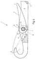
- FIG. 1 illustrates a latch needle 1 which a needle body 2 having a shaft 3, the end is provided with a hook 4.
- the hook is one Tongue 5 assigned in a tongue slot 6 by means a bearing device 7 is pivotally mounted.
- the tongue slot 6 is in the immediate vicinity Neighboring to the hook 4 arranged so that the tongue 5 with her spoon 8 on the one hand touch the hook 4 and thus close a thread space and on the other hand in reserve can get to the shaft 3.
- the tongue slot 6 is of two slot walls 9, 11th limited to which the tongue 5 their flanks 12, 13 turns.
- the tongue slot 6 from the needle top 14 to the needle back 15 by, i. it is open on both sides.
- the tongue 5 is on a tongue hole 16 penetrated by a bearing pin 17, which forms the storage device 7.
- the bearing pin 17 is in the embodiment of Figure 3 approximately midway between the needle top 14 and the needle rear side 15 is arranged.
- the arrangement of the bearing device 7 with respect to the needle top 14 or on the needle back 15 is of the Determine knitting application dependent.
- the tongue hole 16 may be in the end of the tongue 18 in the middle or off-center between tongue shaft bottom 26 and back surface 27th be arranged.
- the provided with the tongue hole 16 end of the tongue. 5 is the end of the tongue 18, with a cleaning profile 19 is provided.
- This is e.g. formed by a step 21, in which the rear end surface 22 their distance to the center 23 of the tongue hole 16 abruptly reduced. It arises by a preferably extending in the radial direction, i.e. in the circumferential direction oriented Räum Chemistry 24, with fairly sharp edges on the flanks 12, 13 of the tongue 5 connects.
- the clearing area closes 24 preferably with a reasonably sharp edge 25 at the end surface 22 at.
- Stage 21 is preferred in line with the tongue hole 16 and the spoon 8 arranged.
- the relevant line L is in FIG. 3 dash-dotted registered. Furthermore, the biggest one is right Distance of the end surface 22 from the center 23 (e.g., measured at the location specified by the line L) with the largest Distance of the tongue shaft bottom 26 or the back surface 27 of the tongue 5 from the center 23 match. To level 24 closes, however, a closer to the middle 23 lying Area 28 of the tongue 5 at.
- the tongue needle 1 described so far works as follows:
- the tongue 5 becomes along its longitudinal direction X moved back and forth.
- the low friction, freely pivotally mounted tongue 5 periodically off the position shown in Figure 3 in solid lines I in the position shown in dashed lines II and back.
- the clearing surface 24 also swings forward and back. It causes so that in the tongue slot. 6 advised dirt every time the tongue 5 out of position II pivots to the position I, from the clearing surface 24th gripped and moved, i. is taken.
- the concerned Dirt is thus on the needle back 15 and on the needle top 14 made out of the tongue slot 6 out.
- FIG. 4 illustrates a modified embodiment the invention. On the above description will based on the same reference numerals accordingly directed. Existing differences are explained below:
- the step 21 is opposite to that above oriented embodiment described. Is located the tongue 5 in the illustrated in Figure 4 reserve (Position I), the Räum preparation 24 to the needle back 15. In addition, the rounding of the edge 25 is slightly larger and the clearing surface 24 is not exactly radially oriented. Of the Region 28 of the end surface 22 follows approximately a radius with respect to the center 23 of the tongue hole 16. Through this Measure will increase the effectiveness of the clearing 24 at the Removing the dirt from the tongue slot 6 increases. In addition, the dirt promotion takes place in each case Needle return, i. at the transition of the tongue 5 from the position I held in position II. The dirt is conveyed Here mainly to the needle back 15 out.
- Figure 5 illustrates a further modified embodiment a tongue 5 with a on the end surface 22nd provided projection 29 as clearing or cleaning profile 19.
- the projection 29 is substantially planar End face 31 provided, the round by sharp edges is limited.
- the end surface 31 includes a sharp edge 32 to the edge 12 and with a sharp edge 33 to the edge 13 at.
- the edges rounded or, if necessary, be sharp.
- FIG 6 Another embodiment of the tongue 5 is shown in FIG 6 illustrates.
- the distance AF from the Back surface 27 to the center 23 is about the same size as the distance AE from the end face 22 to the center 23.
- Das Ratio of AF to AE is in the range of 0.8 to 1.5, preferably it is 1.
- AE is doing on the am farthest from the center 23 farthest portion of the end face 22, i. measured at the end surface 31. This can, As Figure 6 illustrates, provided with a recess 34 which may be the effectiveness of the cleaning even better.
- Stage 21 is also a series of stages 21a, 21b be provided in the same or different Direction are oriented.
- the Tongue shaft base 26 starting from a first radius R in the area of the tongue end 18 at the stage 21a to a first larger value R1 and at the stage 21b a second even greater value R2 over.
- the resulting Reaming surfaces 24a, 24b are preferably oriented approximately radially.
- the radius R rises from the bottom of the tongue shaft 26.
- the stages 21 (21a, 21b) Teeth that serve and which are set up are to detect in the tongue slot 6 penetrated dirt and to transport to the outside.
- FIG. 8 illustrates a further modified embodiment the latch needle 1, in which in the tongue slot 6 is a tongue spring 35 is arranged.
- the functional profile 36 can, for example by a flattening, i. a plane or facet 37 formed flat on the tongue spring 35 rests just before the tongue 5 in full reserve position comes.
- the tongue 5 can be a stable Have reserve position in which they are not quite on the shaft 3 is present.
- the Edge 25 be slightly rounded.
- the clearing surface 24 is used at This embodiment as described above for broaching and cleaning the tongue slot.
- She is at level 21 formed in which the end surface 22 of a radius R1 goes to the radius R.
- the radius is R1 slightly less than the distance of facet 37 from the center 23rd
- Tongue needle 1 illustrates Figure 9.
- the difference to The above-described latch needles is that the Tongue slot 6 only on the needle top 14 open at the Needle back 15 is closed. It can all previously described tongues 5 application find. Especially is an embodiment of the tongue 5 according to Figure 3, 5, 7 or 9 prefers. With particular reference to these figures the above description accordingly.
- a latch needle 1 is provided with a tongue 5, the at its tongue end 18 carries a broaching profile 19.
- the Clearing profile 19 serves the tongue slot 6 of dirt to keep free. It has at least one special Clearing surface 24 on.
Landscapes
- Engineering & Computer Science (AREA)
- Textile Engineering (AREA)
- Knitting Machines (AREA)
- Infusion, Injection, And Reservoir Apparatuses (AREA)
Abstract
Description
- Figur 1
- eine Zungennadel in vereinfachter perspektivischer Darstellung,
- Figur 2
- die Zungennadel nach Figur 1 in einem anderen Maßstab in ausschnittsweiser Darstellung,
- Figur 3
- die Zungennadel in Figur 1 oder 2 in teilweise geschnittener Seitenansicht in einem anderen Maßstab,
- Figur 4
- eine abgewandelte Ausführungsform der Zungennadel in teilweise geschnittener Seitenansicht,
- Figur 5
- eine weitere Ausführungsform einer Zunge für eine Zungennadel in Perspektivdarstellung,
- Fig. 6 und 7
- weitere Ausführungsformen einer Zunge mit unterschiedlichen Reinigungsprofilen in Seitenansicht,
- Figur 8
- eine Ausführungsform einer erfindungsgemäßen Zungennadel mit Zungenfeder in einer teilweise geschnittenen Seitenansicht und
- Figur 9
- eine Ausführungsform einer Zungennadel mit rückseitig geschlossenem Schlitz in teilweise geschnittener Seitenansicht.
- 1
- Zungennadel
- 2
- Nadelkörper
- 3
- Schaft
- 4
- Haken
- 5
- Zunge
- 6
- Zungenschlitz
- 7
- Lagereinrichtung
- 8
- Löffel
- 9, 11
- Schlitzwände
- 12, 13
- Flanken
- 14
- Nadeloberseite
- 15
- Nadelrückseite
- 16
- Zungenloch
- 17
- Lagerzapfen
- 18
- Zungenschaftende
- 19
- Reinigungsprofil
- 21, 21a, 21b
- Stufe
- 22
- Endfläche
- 23
- Mitte
- 24
- Räumfläche
- 25
- Kante
- 26
- Zungenschaftunterseite
- 27
- Rückenfläche
- 28
- Bereich
- 29
- Vorsprung
- 31
- Endfläche
- 32, 33
- Kanten
- 35
- Zungenfeder
- 36
- Funktionsprofil
- 37
- Facette
- AE
- Abstand
- AF
- Abstand
- L
- Linie
- R
- Radius
- X
- Längsrichtung
- I, II
- Positionen
Claims (10)
- Zungennadel (1), insbesondere für Strickmaschinen,
mit einem Nadelkörper (2), der einen endseitig mit einem Haken (4) versehenen Schaft (3) aufweist, der in Hakennähe mit einem Zungenschlitz (6) versehen ist,
mit einer Zunge (5), die in dem Zungenschlitz (6) an einer Zungenlagereinrichtung (7) schwenkbar gelagerte angeordnet und hier mit einem Reinigungsprofil (19) versehen ist. - Zungennadel nach Anspruch 1, dadurch gekennzeichnet, dass die Zunge (5) mittels der Zungenlagereinrichtung (7) ungehemmt frei schwenkbar gelagert ist.
- Zungennadel nach Anspruch 1, dadurch gekennzeichnet, dass sich der Zungenschlitz (6) von einer Nadeloberseite (14) zu einer Nadelrückseite (15) erstreckt und sowohl an der Nadeloberseite (14) als auch an der Nadelrückseite (15) offen ist.
- Zungennadel nach Anspruch 1, dadurch gekennzeichnet, dass das Reinigungsprofil (19) durch ein Zahnprofil an einer Endfläche (22) der Zunge (5) gebildet ist.
- Zungennadel nach Anspruch 1, dadurch gekennzeichnet, dass die Zunge (5) in jeder Schwenklage ausschließlich durch einen Lagerzapfen (17) sowie durch Schlitzwände (9, 11) des Zungenschlitzes (6) geführt ist.
- Zungennadel nach Anspruch 4, dadurch gekennzeichnet, dass zu dem Reinigungsprofil (19) wenigstens eine an der Endfläche (22) ausgebildete Stufe (21) gehört.
- Zungennadel nach Anspruch 4, dadurch gekennzeichnet, dass das Reinigungsprofil (19) wenigstens eine Räumfläche (24) aufweist, die sich bezüglich der Lagereinrichtung (7) im wesentlichen in Radialrichtung erstreckt.
- Zungennadel nach Anspruch 4, dadurch gekennzeichnet, dass die Stufe (21) an einer Stelle der Zunge (5) angeordnet ist, die dem Zungenlöffel (8) gegenüberliegt.
- Zungennadel nach Anspruch 1, dadurch gekennzeichnet, dass in dem Zungenschlitz (6) eine Zungenfeder (35) angeordnet ist, die mit der Zunge (5) zusammenwirkt.
- Zungennadel nach Anspruch 1, dadurch gekennzeichnet, dass das Reinigungsprofil (19) wenigstens eine scharfe Kante (25, 32, 33) aufweist.
Applications Claiming Priority (2)
| Application Number | Priority Date | Filing Date | Title |
|---|---|---|---|
| DE10341630 | 2003-09-10 | ||
| DE10341630A DE10341630B4 (de) | 2003-09-10 | 2003-09-10 | Zungennadel |
Publications (2)
| Publication Number | Publication Date |
|---|---|
| EP1514964A1 true EP1514964A1 (de) | 2005-03-16 |
| EP1514964B1 EP1514964B1 (de) | 2007-04-18 |
Family
ID=34129723
Family Applications (1)
| Application Number | Title | Priority Date | Filing Date |
|---|---|---|---|
| EP04018092A Expired - Lifetime EP1514964B1 (de) | 2003-09-10 | 2004-07-30 | Zungennadel |
Country Status (6)
| Country | Link |
|---|---|
| US (1) | US6931890B2 (de) |
| EP (1) | EP1514964B1 (de) |
| JP (1) | JP2005082957A (de) |
| KR (1) | KR100605243B1 (de) |
| CN (1) | CN1594698B (de) |
| DE (2) | DE10341630B4 (de) |
Families Citing this family (5)
| Publication number | Priority date | Publication date | Assignee | Title |
|---|---|---|---|---|
| EP2088228B1 (de) * | 2008-02-05 | 2011-10-19 | Groz-Beckert KG | Zungennadel |
| EP2172584B1 (de) * | 2008-10-02 | 2013-01-09 | Groz-Beckert KG | Strickmaschinennadel mit geschlitztem Mäanderbogen |
| EP2604359B1 (de) * | 2011-12-14 | 2017-06-14 | Groz-Beckert KG | Zungennadel mit verbesserter Zungenlagerung und Verfahren zu ihrer Herstellung |
| JP6692325B2 (ja) * | 2017-07-07 | 2020-05-13 | 株式会社島精機製作所 | 複合針 |
| EP3604651A1 (de) * | 2018-08-03 | 2020-02-05 | Groz-Beckert KG | Zungennadel |
Citations (3)
| Publication number | Priority date | Publication date | Assignee | Title |
|---|---|---|---|---|
| US1163296A (en) * | 1914-02-13 | 1915-12-07 | Louis N D Williams | Knitting-machine. |
| US20020152774A1 (en) * | 2000-07-22 | 2002-10-24 | Manfred Sauter | Latch needle comprising a relieved latch shank |
| US20040011086A1 (en) * | 2002-07-19 | 2004-01-22 | Groz-Beckert Kg | Latch needle |
Family Cites Families (12)
| Publication number | Priority date | Publication date | Assignee | Title |
|---|---|---|---|---|
| US1032613A (en) * | 1911-06-24 | 1912-07-16 | John J Tuller | Latch knitting-needle. |
| US1732469A (en) * | 1927-05-10 | 1929-10-22 | Rollins Hosiery Mills | Needle for repairing runs in knitted fabrics |
| GB380554A (en) * | 1931-07-25 | 1932-09-22 | Robert Kirkland Mills | Improvements in the means for and method of producing knitted fabric |
| US2536478A (en) * | 1940-04-11 | 1951-01-02 | American Vitos Company Inc | Knitting needle |
| JPS61133586A (ja) | 1984-11-30 | 1986-06-20 | 信越ポリマ−株式会社 | コネクタ− |
| JPS61133586U (de) * | 1985-02-05 | 1986-08-20 | ||
| DE3600620C1 (de) * | 1986-01-11 | 1987-02-12 | Theodor Groz & Soehne & Ernst Beckert Nadelfabrik Kg, 7470 Albstadt, De | |
| DE3702019C1 (de) * | 1987-01-24 | 1987-09-24 | Groz & Soehne Theodor | Zungennadel fuer maschenbildende Textilmaschinen |
| DE4142003C1 (de) * | 1991-12-19 | 1993-07-22 | Theodor Groz & Soehne & Ernst Beckert Nadelfabrik Kg, 7470 Albstadt, De | |
| DE4334051C1 (de) * | 1993-10-06 | 1995-02-16 | Groz & Soehne Theodor | Zungennadel für Textilmaschinen |
| JPH0860504A (ja) * | 1994-08-26 | 1996-03-05 | Tsudakoma Corp | 編機用ベラ針 |
| DE19712124C2 (de) * | 1997-03-22 | 1999-07-01 | Groz Beckert Kg | Zungennadel für maschenbildende Textilmaschinen |
-
2003
- 2003-09-10 DE DE10341630A patent/DE10341630B4/de not_active Expired - Fee Related
-
2004
- 2004-07-30 EP EP04018092A patent/EP1514964B1/de not_active Expired - Lifetime
- 2004-07-30 DE DE502004003519T patent/DE502004003519D1/de not_active Expired - Lifetime
- 2004-08-30 JP JP2004250718A patent/JP2005082957A/ja active Pending
- 2004-09-09 KR KR1020040071982A patent/KR100605243B1/ko not_active Expired - Fee Related
- 2004-09-09 CN CN200410078561XA patent/CN1594698B/zh not_active Expired - Fee Related
- 2004-09-10 US US10/937,604 patent/US6931890B2/en not_active Expired - Fee Related
Patent Citations (3)
| Publication number | Priority date | Publication date | Assignee | Title |
|---|---|---|---|---|
| US1163296A (en) * | 1914-02-13 | 1915-12-07 | Louis N D Williams | Knitting-machine. |
| US20020152774A1 (en) * | 2000-07-22 | 2002-10-24 | Manfred Sauter | Latch needle comprising a relieved latch shank |
| US20040011086A1 (en) * | 2002-07-19 | 2004-01-22 | Groz-Beckert Kg | Latch needle |
Non-Patent Citations (1)
| Title |
|---|
| PATENT ABSTRACTS OF JAPAN vol. 1996, no. 07 31 July 1996 (1996-07-31) * |
Also Published As
| Publication number | Publication date |
|---|---|
| DE502004003519D1 (de) | 2007-05-31 |
| KR100605243B1 (ko) | 2006-07-28 |
| CN1594698B (zh) | 2011-06-15 |
| KR20050026878A (ko) | 2005-03-16 |
| US20050050924A1 (en) | 2005-03-10 |
| JP2005082957A (ja) | 2005-03-31 |
| DE10341630A1 (de) | 2005-04-28 |
| EP1514964B1 (de) | 2007-04-18 |
| US6931890B2 (en) | 2005-08-23 |
| DE10341630B4 (de) | 2006-11-16 |
| CN1594698A (zh) | 2005-03-16 |
Similar Documents
| Publication | Publication Date | Title |
|---|---|---|
| EP0906980B1 (de) | Gestanztes Strickwerkzeug | |
| EP1039003A1 (de) | Schiebernadel mit geteiltem Schieber | |
| EP1094139B1 (de) | Schiebernadel mit asymmetrisch geteiltem schieber | |
| EP1514964B1 (de) | Zungennadel | |
| EP0884412B1 (de) | Strickmaschine, insbesondere Flachstrickmaschine | |
| EP2130960B1 (de) | Stricksystem mit einer nadelgetriebenen Abschlagplatine | |
| EP1908871B1 (de) | Greifer für Tuftingmaschine | |
| DE19750055C2 (de) | Fliesenschneidgerät | |
| DE2745793A1 (de) | Tufting-maschine | |
| EP2088228A1 (de) | Zungennadel | |
| WO2005095703A1 (de) | Geprägte tuftingnadel | |
| EP1416078A1 (de) | Maschenbildungselemente für Strick- und für Kettenwirkmaschinen | |
| EP1619282B1 (de) | Nadel für ein maschenbildendes System | |
| EP1801276B1 (de) | Systemteil für ein Stricksystem | |
| DE10106989C2 (de) | Zungennadel mit fixierter Feder | |
| EP1731651B1 (de) | Zungennadel für Textilmaschinen | |
| DE3406870A1 (de) | Flachstrickmaschine mit elektromechanischer auswahl | |
| DE3509184C2 (de) | ||
| EP1645670B1 (de) | Zungennadel | |
| DE10035827C2 (de) | Zungennadel mit abgesetztem Zungenschaft | |
| EP1270784B1 (de) | Schiebernadel | |
| EP1887117B1 (de) | Zungennadel für maschenbildende Textilmaschine | |
| EP1270785A1 (de) | Schiebernadel mit verbessertem Schieber | |
| EP1873287B1 (de) | Zungennadel für maschenbildende Textilmaschine | |
| DE10035826C2 (de) | Zungennadel mit abgesetztem Zungenschlitz |
Legal Events
| Date | Code | Title | Description |
|---|---|---|---|
| PUAI | Public reference made under article 153(3) epc to a published international application that has entered the european phase |
Free format text: ORIGINAL CODE: 0009012 |
|
| AK | Designated contracting states |
Kind code of ref document: A1 Designated state(s): AT BE BG CH CY CZ DE DK EE ES FI FR GB GR HU IE IT LI LU MC NL PL PT RO SE SI SK TR |
|
| AX | Request for extension of the european patent |
Extension state: AL HR LT LV MK |
|
| 17P | Request for examination filed |
Effective date: 20050819 |
|
| AKX | Designation fees paid |
Designated state(s): DE FR GB IT TR |
|
| GRAP | Despatch of communication of intention to grant a patent |
Free format text: ORIGINAL CODE: EPIDOSNIGR1 |
|
| GRAC | Information related to communication of intention to grant a patent modified |
Free format text: ORIGINAL CODE: EPIDOSCIGR1 |
|
| GRAS | Grant fee paid |
Free format text: ORIGINAL CODE: EPIDOSNIGR3 |
|
| GRAA | (expected) grant |
Free format text: ORIGINAL CODE: 0009210 |
|
| AK | Designated contracting states |
Kind code of ref document: B1 Designated state(s): DE FR GB IT TR |
|
| GBT | Gb: translation of ep patent filed (gb section 77(6)(a)/1977) |
Effective date: 20070501 |
|
| REF | Corresponds to: |
Ref document number: 502004003519 Country of ref document: DE Date of ref document: 20070531 Kind code of ref document: P |
|
| ET | Fr: translation filed | ||
| PLBE | No opposition filed within time limit |
Free format text: ORIGINAL CODE: 0009261 |
|
| STAA | Information on the status of an ep patent application or granted ep patent |
Free format text: STATUS: NO OPPOSITION FILED WITHIN TIME LIMIT |
|
| 26N | No opposition filed |
Effective date: 20080121 |
|
| PGFP | Annual fee paid to national office [announced via postgrant information from national office to epo] |
Ref country code: FR Payment date: 20110729 Year of fee payment: 8 |
|
| PGFP | Annual fee paid to national office [announced via postgrant information from national office to epo] |
Ref country code: GB Payment date: 20110721 Year of fee payment: 8 Ref country code: TR Payment date: 20110704 Year of fee payment: 8 |
|
| PGFP | Annual fee paid to national office [announced via postgrant information from national office to epo] |
Ref country code: IT Payment date: 20110728 Year of fee payment: 8 |
|
| REG | Reference to a national code |
Ref country code: DE Ref legal event code: R119 Ref document number: 502004003519 Country of ref document: DE |
|
| GBPC | Gb: european patent ceased through non-payment of renewal fee |
Effective date: 20120730 |
|
| REG | Reference to a national code |
Ref country code: FR Ref legal event code: ST Effective date: 20130329 |
|
| PG25 | Lapsed in a contracting state [announced via postgrant information from national office to epo] |
Ref country code: GB Free format text: LAPSE BECAUSE OF NON-PAYMENT OF DUE FEES Effective date: 20120730 Ref country code: FR Free format text: LAPSE BECAUSE OF NON-PAYMENT OF DUE FEES Effective date: 20120731 |
|
| PG25 | Lapsed in a contracting state [announced via postgrant information from national office to epo] |
Ref country code: IT Free format text: LAPSE BECAUSE OF NON-PAYMENT OF DUE FEES Effective date: 20120730 |
|
| PG25 | Lapsed in a contracting state [announced via postgrant information from national office to epo] |
Ref country code: TR Free format text: LAPSE BECAUSE OF NON-PAYMENT OF DUE FEES Effective date: 20120730 |
|
| PGFP | Annual fee paid to national office [announced via postgrant information from national office to epo] |
Ref country code: DE Payment date: 20140731 Year of fee payment: 11 |
|
| PG25 | Lapsed in a contracting state [announced via postgrant information from national office to epo] |
Ref country code: DE Free format text: LAPSE BECAUSE OF NON-PAYMENT OF DUE FEES Effective date: 20130201 |