EP1514960A2 - Vibrationsarmes Fachbildesystem - Google Patents
Vibrationsarmes Fachbildesystem Download PDFInfo
- Publication number
- EP1514960A2 EP1514960A2 EP04018431A EP04018431A EP1514960A2 EP 1514960 A2 EP1514960 A2 EP 1514960A2 EP 04018431 A EP04018431 A EP 04018431A EP 04018431 A EP04018431 A EP 04018431A EP 1514960 A2 EP1514960 A2 EP 1514960A2
- Authority
- EP
- European Patent Office
- Prior art keywords
- transmission according
- tab
- extensions
- rigid material
- longitudinal direction
- Prior art date
- Legal status (The legal status is an assumption and is not a legal conclusion. Google has not performed a legal analysis and makes no representation as to the accuracy of the status listed.)
- Withdrawn
Links
- 239000000463 material Substances 0.000 claims abstract description 13
- 230000005540 biological transmission Effects 0.000 claims description 24
- 230000033001 locomotion Effects 0.000 claims description 16
- 229920001971 elastomer Polymers 0.000 claims description 14
- 239000006096 absorbing agent Substances 0.000 claims description 8
- 239000000806 elastomer Substances 0.000 claims description 5
- 239000002184 metal Substances 0.000 claims description 5
- 239000011358 absorbing material Substances 0.000 claims 3
- 229920002430 Fibre-reinforced plastic Polymers 0.000 claims 1
- 239000011151 fibre-reinforced plastic Substances 0.000 claims 1
- 238000013016 damping Methods 0.000 description 17
- 210000002414 leg Anatomy 0.000 description 14
- 238000009941 weaving Methods 0.000 description 8
- 229920003052 natural elastomer Polymers 0.000 description 7
- 229920001194 natural rubber Polymers 0.000 description 7
- 230000035939 shock Effects 0.000 description 7
- 244000043261 Hevea brasiliensis Species 0.000 description 6
- 238000010521 absorption reaction Methods 0.000 description 4
- 230000001154 acute effect Effects 0.000 description 4
- 229910000831 Steel Inorganic materials 0.000 description 3
- 239000004033 plastic Substances 0.000 description 3
- 229920003023 plastic Polymers 0.000 description 3
- 239000010959 steel Substances 0.000 description 3
- 238000004073 vulcanization Methods 0.000 description 3
- 230000001133 acceleration Effects 0.000 description 2
- 230000000295 complement effect Effects 0.000 description 2
- 239000004814 polyurethane Substances 0.000 description 2
- 229920003225 polyurethane elastomer Polymers 0.000 description 2
- 241001417523 Plesiopidae Species 0.000 description 1
- 238000004026 adhesive bonding Methods 0.000 description 1
- 230000002238 attenuated effect Effects 0.000 description 1
- 150000001875 compounds Chemical class 0.000 description 1
- 230000006835 compression Effects 0.000 description 1
- 238000007906 compression Methods 0.000 description 1
- 238000010276 construction Methods 0.000 description 1
- 230000008878 coupling Effects 0.000 description 1
- 238000010168 coupling process Methods 0.000 description 1
- 238000005859 coupling reaction Methods 0.000 description 1
- 230000003247 decreasing effect Effects 0.000 description 1
- 230000001627 detrimental effect Effects 0.000 description 1
- 208000018459 dissociative disease Diseases 0.000 description 1
- 238000005553 drilling Methods 0.000 description 1
- 230000000694 effects Effects 0.000 description 1
- 239000013536 elastomeric material Substances 0.000 description 1
- 230000005284 excitation Effects 0.000 description 1
- 239000000835 fiber Substances 0.000 description 1
- 238000007667 floating Methods 0.000 description 1
- 238000003384 imaging method Methods 0.000 description 1
- 238000003780 insertion Methods 0.000 description 1
- 230000037431 insertion Effects 0.000 description 1
- 238000005461 lubrication Methods 0.000 description 1
- 238000000034 method Methods 0.000 description 1
- 230000010355 oscillation Effects 0.000 description 1
- 230000002028 premature Effects 0.000 description 1
- 238000010025 steaming Methods 0.000 description 1
- 229920003051 synthetic elastomer Polymers 0.000 description 1
- 210000000689 upper leg Anatomy 0.000 description 1
- XLYOFNOQVPJJNP-UHFFFAOYSA-N water Substances O XLYOFNOQVPJJNP-UHFFFAOYSA-N 0.000 description 1
Images


Classifications
-
- D—TEXTILES; PAPER
- D03—WEAVING
- D03C—SHEDDING MECHANISMS; PATTERN CARDS OR CHAINS; PUNCHING OF CARDS; DESIGNING PATTERNS
- D03C9/00—Healds; Heald frames
- D03C9/06—Heald frames
- D03C9/0691—Arrangements of means for damping or noise reduction
-
- D—TEXTILES; PAPER
- D03—WEAVING
- D03C—SHEDDING MECHANISMS; PATTERN CARDS OR CHAINS; PUNCHING OF CARDS; DESIGNING PATTERNS
- D03C1/00—Dobbies
- D03C1/14—Features common to dobbies of different types
- D03C1/16—Arrangements of dobby in relation to loom
-
- D—TEXTILES; PAPER
- D03—WEAVING
- D03C—SHEDDING MECHANISMS; PATTERN CARDS OR CHAINS; PUNCHING OF CARDS; DESIGNING PATTERNS
- D03C9/00—Healds; Heald frames
- D03C9/06—Heald frames
- D03C9/0683—Arrangements or means for the linking to the drive system
Definitions
- the invention relates to a transmission for driving a Weave of a loom.
- Weaving machines have so-called subject imaging systems, which serve to warp up or down from the To move out warp level around a so-called drawer to form the entry of a weft thread.
- the weft insertion systems who work with water or air, for example, have a performance potential for highest weaving speeds on. But this potential can not usually be exhausted, because the existing sumanesysteme resulting from excessive working speed Loads can not withstand.
- the burdens arise from the accelerations when moving up and down the shafts with which the strands are held.
- the Movement is by so-called eccentric or Dobby produced. Even if this is as harmonious as possible Movements are aimed at and realized but in the shedding system and the associated gear, which connects the heald frames with the eccentric machines, vibrations. These load all elements of the tray system and lead to premature wear or breakage of components. Litzenbrüche, warp breaks and resulting Machine downtime results from such inflated Charges.
- CH 558 435 is a weaving sheave drive known to the one between the Webschaft and a Stem transmission arranged linkage heard.
- the linkage contains a tab in which a shock absorber is installed.
- the shock absorber can in a variant as a rubber block be educated. This then connects two of this extending rigid halves of the tab.
- Such a rubber block causes sufficient Vibration damping only at considerable axial compliance, which detrimental to the precision of the shaft movement is. It also provides an additional mass to move in cooperation with other elements, such as playful connections, again source of vibrations can be.
- CH-PS 549 668 is a linkage for the drive of a weave known in place of conventional Hinge joints spring joints has. These are through Leaf springs or rubber blocks formed. The measure serves the reduction of the otherwise encountered wear on the Joints. In addition, the need for lubrication slow reciprocating joints largely avoided become.
- EP 0 870 856 A1 is a for driving a Webschaft provided linkage known that over a sprung Tab is connected to the shaft drive. Is to the tab divided into two parts between those Compression spring package is effective.
- the invention is based Task from which a transmission for transmitting a hinund forthcoming drive movement of a dobby or to create another drive on a hive is, the transmission also very fast shaft movements should allow.
- This object is achieved with a transmission dissolved in the power transmission path at least one tab with longitudinally oriented sandwich structure consisting of different materials is arranged. At least one of the materials used has vibration-absorbing Properties on.
- the longitudinal orientation is on the one hand a lightweight low-mass construction and on the other hand achieved a good vibration absorption. It is special possible to give the flap a high axial rigidity, on the other hand, good vibration absorption properties are reachable. This allows the transmission high axial forces to achieve very fast shaft movements, without accepting positioning inaccuracies, the excitation of vibrations as a result of the jerky Movements through the tab can be greatly reduced.
- the absorber element is planar designed as a closed surface. It can however also as Honeycomb or as a flat, with openings or recesses be provided provided part. It is preferably from a natural or synthetic Elastomer e.g. Natural rubber. It's with the metal or a rigid plastic existing adjacent elements, e.g. area cohesive by gluing or Vulcanization, connected. Alternatively it can also by Rivets or other form-locking connection means held between the other elements of the sandwich assembly be. However, preferred is an arrangement in which the Connection between the two flap parts completely and exclusively by the vibration-absorbing element is created. In such an arrangement, all run in between forces acting on the ends of the tab exclusively through the body of the vibration absorbing element. Detours or other connections between the ends of the flaps, which could be vibration-transmitting, exist Not.
- the tab may be stiffer wall areas of a metal or a rigid plastic, wherein the Vibration absorptive planar absorber element made of rubber or other elastomer is formed. It may be the longitudinally extending rigid wall areas be wedge-shaped, which is a particularly good Vibration absorption allows. It is preferred that stiff wall areas, for example, as parallel-sided Form plate whose longitudinal edges angled for stiffening. The e.g. square angled edges may be wedge-shaped, i.e. its free edge then runs at an acute angle to the remaining planar rigid wall area and thus to the Longitudinal direction.
- the tab described is preferably in arranged directly on a dobby, to a vibration transmission from the dobby on to prevent the linkage from the outset. In the linkage Further tabs according to the invention can be arranged. In addition, it is possible to take further attenuation measures to meet. For example, bearings of angle levers or of joints in damping elements, e.g. Rubber rings to sit.
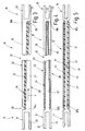
- FIG. 1 illustrates a heddle 1 which is intended for Shedding on a weaving machine not further illustrated arranged and via a linkage 2 of a dobby 3 ago is driven.
- the dobby 3 is For example, an eccentric with an eccentric 4, via a connecting rod 5 serving as an output rocker. 6 driving back and forth.
- the rocker 6 is a Swiveling center 7 pivotally mounted. Your swinging motion is indicated in Figure 1 by an arrow 8.
- the rocker 6 on the weaving shank 1 serving linkage 2 comprises at least two in the present embodiment pivotally mounted angle lever 9, 11, the train and Push rods 12, 13 are connected to the heald 1 to to move it up and down.
- the lower legs of the angle lever 9, 11 are interconnected by a connecting rod 14 connected, the articulated with the respective thighs the angle lever 9, 11 is connected.
- the connecting rod 14 In the middle, the connecting rod 14 to be supported by a rocker 15, the hingedly connected to the connecting rod 14 at one end and stored with its other end to a pivot bearing is.
- connection between the angle lever 9, the Dobby 3 is disposed adjacent, and the dobby 3 is provided by a tab 16, one of which End 17 hinged to a rider 18 is connected to the the rocker 6 sits. Her other end 19 is articulated with connected to the lower leg of the angle lever 9.
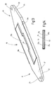
- the tab 16 is illustrated separately in FIG. It is altogether as a vibration-damping element formed, wherein it is stiff in the axial direction. At her Ends 17, 19 is forked. Two flat, parallel mutually oriented legs 21, 22 and 23, 24th in each case limit a space between each other in pairs for receiving the rider 18 and the angle lever 9. A transverse bore 25, 26 serves each of the Recording a bearing pin.
- the tab 16 is illustrated separately in FIG. From the end 17 extends an elongated tongue-like Extension 27 away, which, according to Figure 2, preferably one has rectangular outline. His thickness is also decreasing preferably from the end 17 in the flap longitudinal direction L from.
- the outer surface 28 of the extension 27 lies with the outer surface of the leg 22 in a plane. The inner surface is inclined to this level.
- the outer surface 28 is also located with the outer surface of the leg 24 substantially in one Level.
- the part described so far forms a first Part 16a of the tab 16.
- a complementary trained part 16b whose extension 31 is also in Laschenlteilscardi L is wedge-shaped. His Outer surface 32 is in turn in a common plane with the outer surfaces of the legs 21, 23rd
- each extension 27, 31 is a preferably arranged at an acute angle to the tab longitudinal direction L.
- Groove 33 formed by an elongated flat element 34 is filled from an elastomeric material.
- the element 34 separates the extensions 27, 31 completely from each other, so that they do not touch each other directly.
- Between front ends of the extensions 27, 31 and the respective adjacent ends 17, 19 are each a gap 35, 36 is formed, the one touch even under vibration load in derogation.
- the element 34 is preferably a high material internal damping or high internal friction. It fills the Fugue 33 is preferably complete over its entire width and length and gapless and is glued to the extensions 27, 31 or otherwise e.g. cohesively by vulcanization connected. It can, as illustrated, in parallel or be wedge-shaped.
- the extensions 27, 31 form with the element 34 a Sandwich assembly 37, the one hand, the stiff transmission of driving movements from the end 17 to the end 19 is used and the other hand, shocks and vibrations not or only very imperfectly forwarded. Shock waves or other Vibrations are effectively damped, independently of whether their direction of vibration is longitudinal or transverse to the tab longitudinal direction L stands.
- the rocker 6 performs a reciprocating Movement in the context of them in their extreme situations each more or less briefly essentially remains.
- the Swiveling the rocker 6 from one extreme to another then takes place in each case in a short quick pivoting movement with a strong acceleration from the one dead center out and with a strong braking when entering in the other dead center.
- This movement is via the tab 16 on the angle lever 9 and via the connecting rod 14 passed the angle lever 11, whereby the weaving 1 is raised or lowered.
- healds held with longitudinal play during this abrupt positioning process abut on their Litzentragschienen and here initiate significant vibrations in the hive.
- Furthermore From the hedge itself emanate vibrations that, like the High-frequency vibrations of healds, in the linkage 2 reach.
- the tab 16 according to Figure 3 of two identical Parts 16a, 16b is composed, the tab 16 ' according to Figure 4 from different, but complementary to each other Divide 16'a, 16'b.
- the extension 27 of the part 16'a extends parallel to the median plane of the part in question and rejuvenates to its free Wedge-shaped towards the end.
- the extension 31 of the part 16'b is forked. His two legs 38, 39 have parallel to each other Outside surfaces 28, 32 on.
- the extension 27 touches the Legs 38, 39 not.
- the remaining between the elements, here v-shaped, joint 33 has a constant Strength and is of the elastomeric element 34 completed.
- the element 34 constitutes a cohesive Connection between the leg 38, the extension 27 and the Leg 39, whereby in turn the sandwich arrangement 37 is formed.
- FIG. 5 illustrates a further modified embodiment the connecting strap as a connecting strap 16 ", which in turn is based on two consensus forms Divide 16 "a, 16" b, these are not here each other overlap. Rather, the wedge-shaped or extend parallel flanked extensions 27, 31 in the same Level towards each other, with the end faces of their ends together limit a gap 41. On both sides of the flat both extensions 27, 31 are for damping and vibration absorption serving plate-shaped elements 34, 42 and are connected to them flat, e.g. bonded. At her Outside are the elements 34, 42 with in the plate longitudinal direction L oriented rigid cover plates 43, 44 provided, the e.g. glued or vulcanized. The Elements 34, 42 may, like the cover plates 43, 44 a longitudinal direction have the same thickness.
- the cover plates 43, 44 double wedge-shaped form so that they are adjacent to the ends 17, 19 respectively their lowest and in the middle at the gap 41st each have their greatest thickness.
- this lug 16 " provides good vibration damping at high axial Stiffness.
- the parts 16a, 16b, 16'a, 16'b and 16 "a, 16" b Can be made of metal or a fiber reinforced rigid plastic be educated. This can, for example, in the area the legs 21, 22, 23, 24 provided with metal inserts be.
- the material of the element 34 is preferably a Material with low internal damping, for example, a Polyurethane or natural rubber.
- Such a flap 16, 16 ', 16 " can be used as a connecting element of a linkage to drive a heald 1 to a dobby 3 or otherwise Drive as well as a connecting element within serve the linkage.
- FIG. 6 Another modified and currently preferred embodiment
- the tab 16 according to the invention is shown in FIG. 6 illustrated.
- the full content of the explanation will be explained the description of the tab 16 referenced according to Figure 3, wherein the following differences apply:
- the extensions 27, 31 extend as a flat plate-like Elements away from the ends 17, 19, being parallel are arranged to each other. Between the extensions 27, 31 is arranged here the thicker formed element 34, which consists of polyurethane or natural rubber, and the thickness of which substantially exceeds the thickness of the extensions 27, 31. To stiffen the extensions 27, 31 can their be bent longitudinal edges, with the edges the extensions 27, 31 preferably do not touch. The Free edges of these bent edges can be straight be.
- FIG. 7 illustrates a modified embodiment, in which these edges are not rectilinear are to crack the flaps emergency running properties or breakage of the element 34. Which is different from the Extension 27 approximately at right angles away extending edge 46 has a serrated edge 47 on.
- the from the extension 31st approximately at right angles to the edge 46 to extending edge 48th also has a serrated edge 49.
- the teeth of the Edges 46, 48 interlock without touching. she can be rectangular or, as shown, trapezoidal Pinnacles or prongs be formed whose distance from each other is so large that picked up by the element 34 vibrations do not lead to edge contact. Tears or breaks However, the element 34, the form-fitting into each other Crossing battlements 46, 48 a movement transmission and thus coupling of the parts 16a, 16b of the tab 16 which guarantees certain emergency running properties.
- the gap between the edges 46, 48 can also, as in Figure 8 is illustrated, straight and in the acute angle to the longitudinal direction of the tab 16 according to FIG 6 be arranged.
- the edges 46, 48 close preferably seamlessly to the respective end 17, 19, whereby They contribute greatly to the stiffening of the tab 16.
- Figures 10 and 11 illustrate the arrangement of the element 34 in which of the extensions 27, 31 and their Edges 46, 48 surround the interior. Preferably closes the element 34 with the edges 46, 48 and also on the Each side of a gap, creating a largely homogeneous loading of the element 34 is achieved.
- This is largely based on the Embodiment of the tab 16 'according to FIG. 4 with the difference that that the extension 27 and the legs 38, 39 respectively not wedge-shaped but as thin-walled, parallel-flanked or parallel-surface components are formed. Otherwise Reference is made to the description of Figure 4.
- the edges the legs 38, 39 may be angled and similar Figure 10 or Figure 11. It is also possible, the edges of the Anvil 27 angled, making this a flat U-profile or receives a Z-profile.
- Regarding the border design can resort to the principles of Figure 7 or 8 are, i. the resulting joints can be straightforward, straight or diagonally arranged or as a jagged line be educated.
- the presented tab can according to Figure 1 as a compound between the dobby 3 and the other linkage 2 serve. It is also possible, the connecting rod 14th form according to the structure of the tab 16. Likewise the pull and push rods 12, 13 elements such as the tabs 16 contain or be designed as such. It is next possible, the angle lever 9, 11 in the manner presented train. To the embodiment of Figure 7 remains Note that to secure the emergency running properties too One or more rivets may be provided, which are the tab 16 transversely and in a way floating are stored. For example, they can be fixed in the element 34 sit and the extensions 27, 31 at holes without edge contact succeed. Round heads can float over the Outside surfaces 28, 32 of the extensions 27, 31 may be arranged. By way of illustration, this is shown by a dashed line in FIG shown rivet 50 indicated.
- FIG. 12 illustrates a tab 16 which has proved to be particularly suitable.
- the peculiarity this tab 16 is that extending from their ends 17, 19 extending away extensions 27, 31 respectively in Extensions 27a, 27b, 31a (see Figure 13), 31b divided are.
- the extensions 27a, 27b extend, in particular 14 can be seen at different Flat sides of the damping element 34 along, where they Do not overlap or overlap significantly.
- the Projections 27a, 27b about half as wide as the element 34th While the extension 27a arranged at the top left is, the extension 27b is arranged at the bottom right.
- the extensions 31a, 31b which differ from extending from the end 19, also about halfway wide as the damping element 34 is formed.
- the extension 31 b is on the right half of the top of the element 34 is arranged.
- the extent symmetrical arrangement is called alternating symmetrical Arrangement called.
- the tab according to the figures 12 to 14 can be rotated about its longitudinal axis by 180 °, wherein then from the point of view of the damping element again the same conditions be created.
- the extensions 27a, 31b define one another between each other Slit 51.
- the extensions 31a, 27b define between each other a gap 52.
- Figures 12 and 13 each illustrate, preferably a few millimeters wide and he can, as illustrated, formed meandering be. It is oriented in the longitudinal direction of the tab. He can alternatively straight (not meandering) formed. In addition, it can be at an acute angle to the longitudinal direction be arranged.
- the extensions 27a to 31b are at their outer edges each angled and engage there in each other to the element 34 to live outside.
- the element 34 is with these angled edges preferably not connected. It consists in a preferred embodiment of an elastomer on natural rubber basis. It will be with the steel existing extensions 27a to 31b connected by vulcanization.
- the cushioning member 34 may be made of natural rubber or a material based on natural rubber.
- a novel linkage 2 for driving a hive 1 contains at least one tab 16, which is used for vibration damping an oriented in the longitudinal direction L of the lug 16 sandwich structure 37 has. Belongs to the sandwich structure at least one longitudinally extending rigid Element 27, which is connected to one end 17 of the tab 16 is also a substantially longitudinal direction extending second rigid member 31, with the other End 19 is connected and an interposed planar damping, also in the longitudinal direction extending element 34.
- the element 34 causes the mechanical Connection of the two parts 16a, 16b of the tab 16 exclusively.
- the rigid elements 27, 31 are opposite Formed wedges, thus in the longitudinal direction one set in opposite directions changing characteristic impedance. This causes a deliberate coupling-technical mismatch in terms of vibration transmission. That between them arranged element 34 dampens the vibrations in addition, so that the tab 16 drives like a filter transmits and destroys or absorbs spurious vibrations.
Landscapes
- Engineering & Computer Science (AREA)
- Textile Engineering (AREA)
- Vibration Prevention Devices (AREA)
- Transmission Devices (AREA)
- Connection Of Plates (AREA)
- Springs (AREA)
- Looms (AREA)
- Vibration Dampers (AREA)
Abstract
Description
- Figur 1
- einen Webschaft mit Gestänge und Schaftmaschine in schematisierter Vorderansicht,
- Figur 2
- eine Lasche des Gestänges nach Figur 1 in perspektivischer Ansicht,
- Figur 3
- die Lasche nach Figur 2 in einer ausschnittsweisen Draufsicht in einem anderen Maßstab,
- Figur 4 und 5
- abgewandelte Ausführungsformen der Verbindungslasche jeweils in abschnittsweiser Draufsicht,
- Figur 6
- eine weitere Ausführungsform einer erfindungsgemäßen Lasche im Längsschnitt,
- Figur 7
- eine Ausführungsvariante der Lasche nach Figur 6 in Draufsicht,
- Figur 8
- eine weitere Ausführungsvariante der Lasche nach Figur 6 in Draufsicht,
- Figur 9
- eine Ausführungsform der erfindungsgemäßen Lasche mit symmetrischem Längsschnitt,
- Figur 10
- die Lasche nach Figur 8, geschnitten entlang der Linie X-X,
- Figur 11
- die Lasche nach Figur 8, geschnitten entlang der Linie XI-XI,
- Figur 12
- eine wechselsymmetrische Ausführungsform der Lasche in einer perspektivischen Ansicht ihrer vorderen Flachseite,
- Figur 13
- die wechselsymmetrische Ausführungsform der Lasche nach Figur 12 in einer perspektivischen Ansicht ihrer hinteren Flachseite und
- Figur 14
- die wechselsymmetrische Ausführungsform der Lasche in einer Querschnittsdarstellung.
- 1
- Webschaft
- 2
- Gestänge
- 3
- Schaftmaschine
- 4
- Exzenter
- 5
- Pleuel
- 6
- Schwinge
- 7
- Schwenkzentrum
- 8
- Pfeil
- 9, 11
- Winkelhebel
- 12, 13
- Zug- und Druckstangen
- 14
- Verbindungsstange
- 15
- Schwinge
- 16
- Lasche
- 16a, 16b
- Teile
- 17
- Ende
- 18
- Reiter
- 19
- Ende
- 21, 22, 23, 24
- Schenkel
- 25, 26
- Bohrung
- 27, 27a, 27b
- Fortsatz
- 28
- Außenfläche
- 31, 31a, 31b
- Fortsatz
- 32
- Außenfläche
- 33
- Fuge
- 34
- Element
- 35, 36
- Spalt
- 37
- Sandwichanordnung
- 38, 39
- Schenkel
- 41
- Spalt
- 42
- Element
- 43, 44
- Abdeckplatten
- 46, 48
- Rand
- 47, 49
- Kante
- 50
- Niet
- 51, 52
- Spalt
- L
- Längsrichtung
Claims (11)
- Getriebe (2) zur Übertragung einer hin und her gehenden Antriebsbewegung einer Schaftmaschine (3) auf einen Webschaft (1),
das sich von einem zum Anschluss an die Schaftmaschine (3) eingerichteten Eingang (17) zu einem zur Verbindung mit dem Webschaft (1) eingerichteten Abtrieb (12, 13) erstreckt und das wenigstens eine zwei Enden (17, 19) aufweisende Verbindungslasche (16) enthält, in der eine sich in Laschenlängsrichtung (L) erstreckende Sandwichanordnung (37) bestehend aus wenigstens einem flächenhaften Fortsatz (27, 31) aus steifen Material und wenigstens einem flächenhaften Absorberelement (34) aus schwingungsabsorbierendem Material untergebracht ist. - Getriebe nach Anspruch 1, dadurch gekennzeichnet, dass das schwingungsabsorbierende Material ein Elastomer ist.
- Getriebe nach Anspruch 1, dadurch gekennzeichnet, dass das steife Material ein faserverstärkter Kunststoff ist.
- Getriebe nach Anspruch 1, dadurch gekennzeichnet, dass das steife Material ein Metall ist.
- Getriebe nach Anspruch 1, dadurch gekennzeichnet, dass zu der Sandwichanordnung (37) ein erster, den Fortsatz (27) aus steifem Material bildender Wandabschnitt gehört, der mit einem der Enden (17) verbunden ist, und
dass zu der Sandwichanordnung (37) ein zweiter, einen weiteren Fortsatz (31) aus steifem Material bildender Wandabschnitt gehört, der mit dem anderen der Enden (19) verbunden ist, und
dass zwischen den beiden Fortsätzen (27, 31) das flächenhafte Absorberelement (34) angeordnet ist. - Getriebe nach Anspruch 5, dadurch gekennzeichnet, dass die Wandabschnitte (27, 31) in Längsrichtung gegensinnig keilförmig ausgebildet sind.
- Getriebe nach Anspruch 5, dadurch gekennzeichnet, dass das Absorberelement (34) eine Platte mit entlang der Längsrichtung konstanter Dicke ist.
- Getriebe nach Anspruch 5, dadurch gekennzeichnet, dass das Absorberelement (34) durch eine zwischen den Wandabschnitten (27, 31) angeordnete Elastomerschicht gebildet ist.
- Getriebe nach Anspruch 1, dadurch gekennzeichnet, dass sich die Sandwichanordnung (37) von einem Ende (17) zu dem anderen Ende (19) der Verbindungslasche (16) erstreckt.
- Getriebe nach Anspruch 1, dadurch gekennzeichnet, dass die Lasche (16) den Eingang des Gestänges (2) bildet.
- Getriebe nach Anspruch 1, dadurch gekennzeichnet, dass die Sandwichanordnung (37) gebildet ist, indem sich von einem Ende (17) zwei flächenhafte Fortsätze (27a, 27b) und von dem anderen Ende (19) ebenfalls zwei flächenhafte Fortsätze (31a, 31b) aus steifen Material weg erstrecken, wobei das Absorberelement (34) aus schwingungsabsorbierendem Material jeweils zwischen zwei mit unterschiedlichen Enden (17, 19) verbundenen Fortsätzen (27a, 31a bzw. 27b, 31b) gehalten ist.
Applications Claiming Priority (2)
| Application Number | Priority Date | Filing Date | Title |
|---|---|---|---|
| DE10341629A DE10341629B4 (de) | 2003-09-10 | 2003-09-10 | Vibrationsarmes Fachbildesystem |
| DE10341629 | 2003-09-10 |
Publications (2)
| Publication Number | Publication Date |
|---|---|
| EP1514960A2 true EP1514960A2 (de) | 2005-03-16 |
| EP1514960A3 EP1514960A3 (de) | 2005-12-07 |
Family
ID=34129722
Family Applications (1)
| Application Number | Title | Priority Date | Filing Date |
|---|---|---|---|
| EP04018431A Withdrawn EP1514960A3 (de) | 2003-09-10 | 2004-08-04 | Vibrationsarmes Fachbildesystem |
Country Status (7)
| Country | Link |
|---|---|
| US (1) | US7032624B2 (de) |
| EP (1) | EP1514960A3 (de) |
| JP (1) | JP4029080B2 (de) |
| KR (1) | KR100618935B1 (de) |
| DE (1) | DE10341629B4 (de) |
| RU (1) | RU2280112C2 (de) |
| TW (1) | TWI251629B (de) |
Cited By (4)
| Publication number | Priority date | Publication date | Assignee | Title |
|---|---|---|---|---|
| KR100618935B1 (ko) * | 2003-09-10 | 2006-09-04 | 그로츠-베케르트 카게 | 저진동 쉐딩 시스템 |
| EP1988195A1 (de) * | 2007-05-04 | 2008-11-05 | Staubli Faverges | Verbindungsstange für Zugsystem und Webrahmen, der eine solche Verbindungsstange umfasst |
| CN104213318A (zh) * | 2014-08-07 | 2014-12-17 | 扬中市金德纺织机械设备厂 | 高速织机 |
| EP3112509A1 (de) * | 2015-07-02 | 2017-01-04 | NV Michel van de Wiele | Verbindungselement zum verbinden von elementen eines fachbildungsmechanismus für eine webmaschine |
Families Citing this family (24)
| Publication number | Priority date | Publication date | Assignee | Title |
|---|---|---|---|---|
| DE10260075B4 (de) * | 2002-12-19 | 2007-02-01 | Groz-Beckert Kg | Schaftrahmen und Webschaft für Webmaschinen |
| DE10343377B3 (de) * | 2003-09-17 | 2005-04-28 | Groz Beckert Kg | Schaftantrieb für Webmaschinenschäfte |
| BE1016217A5 (nl) * | 2004-09-28 | 2006-05-02 | Wiele Michel Van De Nv | Gaapvormingsinrichting en weefmachine voorzien van dergelijke gaapvormingsinrichting. |
| DE102004047929B3 (de) * | 2004-10-01 | 2005-12-01 | Groz-Beckert Kg | Verbesserter Webschaft |
| DE102005029699B3 (de) * | 2005-06-24 | 2007-02-08 | Groz-Beckert Kg | Webschaft |
| DE102005059911B3 (de) * | 2005-12-15 | 2007-02-08 | Groz-Beckert Kg | Schaftantrieb für eine Webmaschine |
| US20080053555A1 (en) * | 2006-07-19 | 2008-03-06 | Groz-Beckert Kg | Shaft drive transmission and coupling rod |
| CN100451200C (zh) * | 2006-08-18 | 2009-01-14 | 王占洪 | 编织机牵引杆连接扣 |
| DE102006057833B3 (de) * | 2006-12-08 | 2008-09-04 | Groz-Beckert Kg | Schaftstab für einen Webschaft |
| US7722065B2 (en) * | 2007-04-10 | 2010-05-25 | Arvinmeritor Technology, Llc | Composite spring with resilient attachment interface |
| EP2037019B1 (de) * | 2007-09-11 | 2009-12-09 | Groz-Beckert KG | Geklebte Litzentragschiene |
| US20090222097A1 (en) * | 2008-02-28 | 2009-09-03 | Warsaw Orthopedic, Inc. | Nucleus implant and method of installing same |
| FR2952150B1 (fr) * | 2009-11-02 | 2012-02-24 | Airbus Operations Sas | Bielle structurale comportant un mode filtrant des vibrations |
| KR101180942B1 (ko) * | 2009-12-04 | 2012-09-07 | 현대자동차주식회사 | 서스펜션 암 |
| EP2530194B1 (de) * | 2011-06-01 | 2014-03-05 | Groz-Beckert KG | Drehereinrichtung mit Hebelgetriebe und Abdeckteil |
| DE102012101730A1 (de) * | 2012-03-01 | 2013-09-05 | Benteler Automobiltechnik Gmbh | Kraftfahrzeugachsaufhängung mit Längsblattfeder |
| EP2689943B1 (de) * | 2012-07-27 | 2018-06-06 | Engineering Developments for Automotive Industry, S.L. | Stabilisator für Fahrzeuge |
| DE102014202581A1 (de) * | 2014-02-12 | 2015-08-13 | Muhr Und Bender Kg | Blattfeder und Blattfederanordnung |
| CN104153109A (zh) * | 2014-07-22 | 2014-11-19 | 扬中市金德纺织机械设备厂 | 高速织机连杆总成 |
| CN106151494A (zh) * | 2015-04-28 | 2016-11-23 | 徐工集团工程机械股份有限公司 | 一种工程机械的传动系统及其控制方法 |
| ES2886131T3 (es) * | 2018-12-13 | 2021-12-16 | Muelles Y Ballestas Hispano Alemanas Projects S L | Ballesta, procedimiento y molde de fabricación de dicha ballesta |
| CN109402828A (zh) * | 2018-12-21 | 2019-03-01 | 常熟纺织机械厂有限公司 | 宽幅无梭织机的下置式开口连杆结构 |
| EP3792382B1 (de) * | 2019-09-10 | 2024-02-07 | Groz-Beckert KG | Webblatt mit einer vielzahl von lamellen |
| CN112725976A (zh) * | 2020-12-29 | 2021-04-30 | 江苏牛牌纺织机械有限公司 | 一种装载有十四片凸轮片的凸轮轴机构及其应用 |
Citations (4)
| Publication number | Priority date | Publication date | Assignee | Title |
|---|---|---|---|---|
| CH549668A (de) | 1971-07-02 | 1974-05-31 | Elitex Zavody Textilniho | Mechanismus mit hin- und herbeweglichen gliedern, insbesondere schafteinrichtung von webstuehlen. |
| CH558435A (de) | 1972-11-17 | 1975-01-31 | Grob & Co Ag | Webeschaftantrieb. |
| DE29611305U1 (de) | 1996-06-28 | 1996-09-12 | Lindauer Dornier Gmbh, 88131 Lindau | Einrichtung zur Schwingungsdämpfung von Webschäften |
| EP0870856A1 (de) | 1997-04-09 | 1998-10-14 | Sulzer Rüti Ag | Webschafttrieb und Webmaschine mit einem Webschafttrieb |
Family Cites Families (28)
| Publication number | Priority date | Publication date | Assignee | Title |
|---|---|---|---|---|
| US1891912A (en) * | 1930-07-24 | 1932-12-27 | Earl C Bunnell | Means and method of producing fabric |
| US2282223A (en) * | 1940-05-28 | 1942-05-05 | Hamilton Wallace | Loom |
| US2969971A (en) * | 1958-07-23 | 1961-01-31 | Minnesota Mining & Mfg | Reinforced plastic springs |
| US3067484A (en) * | 1959-09-10 | 1962-12-11 | Russell Mfg Co | Fabric web |
| US3095187A (en) * | 1960-06-20 | 1963-06-25 | Cons Kinetics Corp | Apparatus for isolating vibrations |
| US3171622A (en) * | 1962-01-02 | 1965-03-02 | Ford Motor Co | Resilient mount |
| US3968958A (en) * | 1972-11-30 | 1976-07-13 | Edgewater Corporation | Composite material springs and manufacture |
| CH623364A5 (en) * | 1977-11-16 | 1981-05-29 | Sulzer Ag | Heald-frame drive for weaving machines. |
| LU80296A1 (fr) * | 1978-09-28 | 1980-04-21 | Bekaert Sa Nv | Structures amortissant des vibrations mecaniques |
| DE2933699C3 (de) * | 1979-08-21 | 1982-02-25 | Lindauer Dornier Gmbh, 8990 Lindau | Anhängevorrichtung des Schaftzuges am Webschaftrahmen |
| DE3009020C2 (de) * | 1980-03-08 | 1984-04-12 | FAG Kugelfischer Georg Schäfer KGaA, 8720 Schweinfurt | Lösbare Hebelverbindung |
| US4530490A (en) * | 1982-08-20 | 1985-07-23 | Nhk Spring Co., Ltd. | Fiber-reinforced plastics leaf spring |
| US4772044A (en) * | 1983-08-22 | 1988-09-20 | Booher Benjamin V | Vehicle suspension system with flexible control arm |
| DE3541042C1 (de) * | 1985-11-19 | 1987-01-29 | Grob & Co Ag | Vorrichtung zum Kuppeln eines Webschaftes mit einem Antriebsorgan |
| CH670114A5 (de) * | 1986-04-11 | 1989-05-12 | Sulzer Ag | |
| FR2631668B2 (fr) * | 1988-01-15 | 1993-11-12 | Hutchinson | Supports elastiques de suspension |
| CH679869A5 (de) * | 1988-10-04 | 1992-04-30 | Sulzer Ag | |
| FR2676467B1 (fr) * | 1991-05-15 | 1995-04-07 | Staubli Sa Ets | Mecanisme de tirage a bielles interpose entre une mecanique d'armure et les cadres de lisses d'un metier a tisser. |
| FR2677723A1 (fr) * | 1991-06-14 | 1992-12-18 | Aerospatiale | Dispositif de liaison elastique entre deux pieces, procede de fabrication de ce dispositif, et installation pour la mise en óoeuvre de ce procede. |
| SE470313B (sv) * | 1992-06-10 | 1994-01-17 | Aelmhults Bruk Ab | Anordning vid vävmaskin innefattande individuellt styrda skaftramar |
| IT1258971B (it) * | 1992-06-11 | 1996-03-11 | Costantino Vinciguerra | Tirante perfezionato di collegamento registrabile tra la ratiera e le leve a squadra della tiranteria di comando quadri di un telaio tessile |
| FR2705972B1 (fr) * | 1993-06-03 | 1995-07-21 | Staubli Sa Ets | Dispositif amortisseur pour machine à tisser. |
| DE19915815C1 (de) * | 1999-04-08 | 2000-09-28 | Schmeing Gmbh & Co | Hebelitze zur Bildung einer Dreherkante |
| US6524692B1 (en) * | 2000-05-02 | 2003-02-25 | Structured Composites, Lp | Energy absorbing structural laminate |
| IT1318130B1 (it) * | 2000-07-06 | 2003-07-23 | Nuova O M V S R L | Traversa a piu' componenti per quadri portalicci a rumorosita' ridotta di telai di tessitura. |
| US6460838B1 (en) * | 2001-04-10 | 2002-10-08 | Visteon Global Technologies, Inc. | Fiber reinforced suspension member |
| FR2836488B1 (fr) * | 2002-02-28 | 2004-06-04 | Staubli Sa Ets | Mecanisme de tirage, son procede de fabrication et metier a tisser comprenant un tel mecanisme |
| DE10341629B4 (de) * | 2003-09-10 | 2007-04-12 | Groz-Beckert Kg | Vibrationsarmes Fachbildesystem |
-
2003
- 2003-09-10 DE DE10341629A patent/DE10341629B4/de not_active Expired - Fee Related
-
2004
- 2004-08-04 EP EP04018431A patent/EP1514960A3/de not_active Withdrawn
- 2004-09-07 JP JP2004260243A patent/JP4029080B2/ja not_active Expired - Fee Related
- 2004-09-09 KR KR1020040071980A patent/KR100618935B1/ko not_active Expired - Fee Related
- 2004-09-09 TW TW093127221A patent/TWI251629B/zh not_active IP Right Cessation
- 2004-09-10 US US10/937,427 patent/US7032624B2/en not_active Expired - Fee Related
- 2004-09-10 RU RU2004127211/12A patent/RU2280112C2/ru not_active IP Right Cessation
Patent Citations (4)
| Publication number | Priority date | Publication date | Assignee | Title |
|---|---|---|---|---|
| CH549668A (de) | 1971-07-02 | 1974-05-31 | Elitex Zavody Textilniho | Mechanismus mit hin- und herbeweglichen gliedern, insbesondere schafteinrichtung von webstuehlen. |
| CH558435A (de) | 1972-11-17 | 1975-01-31 | Grob & Co Ag | Webeschaftantrieb. |
| DE29611305U1 (de) | 1996-06-28 | 1996-09-12 | Lindauer Dornier Gmbh, 88131 Lindau | Einrichtung zur Schwingungsdämpfung von Webschäften |
| EP0870856A1 (de) | 1997-04-09 | 1998-10-14 | Sulzer Rüti Ag | Webschafttrieb und Webmaschine mit einem Webschafttrieb |
Cited By (7)
| Publication number | Priority date | Publication date | Assignee | Title |
|---|---|---|---|---|
| KR100618935B1 (ko) * | 2003-09-10 | 2006-09-04 | 그로츠-베케르트 카게 | 저진동 쉐딩 시스템 |
| EP1988195A1 (de) * | 2007-05-04 | 2008-11-05 | Staubli Faverges | Verbindungsstange für Zugsystem und Webrahmen, der eine solche Verbindungsstange umfasst |
| FR2915754A1 (fr) * | 2007-05-04 | 2008-11-07 | Staubli Faverges Sca | Bielle pour systeme de tirage et metier a tisser comprenant une telle bielle. |
| KR101466109B1 (ko) * | 2007-05-04 | 2014-11-27 | 스또블리 파베르쥬 | 드로우 시스템용 커넥팅 로드 및 상기 커넥팅 로드를포함하는 직조기 |
| CN104213318A (zh) * | 2014-08-07 | 2014-12-17 | 扬中市金德纺织机械设备厂 | 高速织机 |
| EP3112509A1 (de) * | 2015-07-02 | 2017-01-04 | NV Michel van de Wiele | Verbindungselement zum verbinden von elementen eines fachbildungsmechanismus für eine webmaschine |
| WO2017001324A1 (en) * | 2015-07-02 | 2017-01-05 | Nv Michel Van De Wiele | Connecting member for connecting elements of a shed forming mechanism for a weaving machine with each other |
Also Published As
| Publication number | Publication date |
|---|---|
| KR20050026877A (ko) | 2005-03-16 |
| US7032624B2 (en) | 2006-04-25 |
| EP1514960A3 (de) | 2005-12-07 |
| RU2280112C2 (ru) | 2006-07-20 |
| US20050051228A1 (en) | 2005-03-10 |
| TW200525058A (en) | 2005-08-01 |
| TWI251629B (en) | 2006-03-21 |
| JP4029080B2 (ja) | 2008-01-09 |
| DE10341629A1 (de) | 2005-05-25 |
| JP2005082958A (ja) | 2005-03-31 |
| RU2004127211A (ru) | 2006-02-20 |
| KR100618935B1 (ko) | 2006-09-04 |
| DE10341629B4 (de) | 2007-04-12 |
Similar Documents
| Publication | Publication Date | Title |
|---|---|---|
| DE10341629B4 (de) | Vibrationsarmes Fachbildesystem | |
| DE112005003288T5 (de) | Tragstruktur für eine Fahrzeugantriebseinheit | |
| EP1528130B1 (de) | Webschaft in Verbundbauweise | |
| DE3490291T1 (de) | Riemen für ein stufenloses Getriebe, querliegendes Riemenglied und diesbezügliche Herstellungsverfahren | |
| EP1120170A2 (de) | Siebvorrichtung | |
| DE202009000264U1 (de) | Dämpfungselement | |
| DE3736126C2 (de) | ||
| EP1992724B1 (de) | Zweiteilbarer Webschaft | |
| DE102010019704B4 (de) | Schiffchen-Stickmaschine mit Antrieb des Treiberbalkens | |
| DE202014104665U1 (de) | Fördereinrichtung mit einem flächig ausgedehnten Förderorgan | |
| EP1526197B1 (de) | Webschaft mit Mittelverbinder | |
| EP0945297B1 (de) | Abgasanlage für ein Kraftfahrzeug | |
| DE10319959B4 (de) | Webschaft für eine Webmaschine | |
| DE102019115871A1 (de) | Aufgabeeinheit für eine Aufbereitungsanlage, insbesondere eine Brech- oder Siebanlage | |
| DE102004055381B3 (de) | Schafstab für Webschäfte | |
| AT408642B (de) | Triebfahrzeug, insbesondere eisenbahn-hochgeschwindigkeits-triebfahrzeug | |
| DE2131922A1 (de) | Kettensaege | |
| DE102009040230A1 (de) | Schneidvorrichtung für eine landwirtschaftliche Maschine | |
| EP1613800B1 (de) | Antrieb für webschäfte einer webmaschine | |
| DE102017213253B3 (de) | Fahrzeug mit einem in einer Schwingrichtung schwingbaren Fahrzeugaufbau | |
| DE4232444C2 (de) | Ski, insbesondere Alpinski | |
| DE102006033328B3 (de) | Schaftantriebsgetriebe und Koppelstange | |
| WO2015036217A1 (de) | Spannvorrichtung für einer kraftrad kette | |
| DE102013210235A1 (de) | Drehmomentstütze für ein Schienenfahrzeug | |
| DE2425953A1 (de) | Niedrig bauende siebmaschine |
Legal Events
| Date | Code | Title | Description |
|---|---|---|---|
| PUAI | Public reference made under article 153(3) epc to a published international application that has entered the european phase |
Free format text: ORIGINAL CODE: 0009012 |
|
| AK | Designated contracting states |
Kind code of ref document: A2 Designated state(s): AT BE BG CH CY CZ DE DK EE ES FI FR GB GR HU IE IT LI LU MC NL PL PT RO SE SI SK TR |
|
| AX | Request for extension of the european patent |
Extension state: AL HR LT LV MK |
|
| PUAL | Search report despatched |
Free format text: ORIGINAL CODE: 0009013 |
|
| AK | Designated contracting states |
Kind code of ref document: A3 Designated state(s): AT BE BG CH CY CZ DE DK EE ES FI FR GB GR HU IE IT LI LU MC NL PL PT RO SE SI SK TR |
|
| AX | Request for extension of the european patent |
Extension state: AL HR LT LV MK |
|
| 17P | Request for examination filed |
Effective date: 20060121 |
|
| AKX | Designation fees paid |
Designated state(s): AT BE BG CH CY CZ DE DK EE ES FI FR GB GR HU IE IT LI LU MC NL PL PT RO SE SI SK TR |
|
| 17Q | First examination report despatched |
Effective date: 20090129 |
|
| GRAP | Despatch of communication of intention to grant a patent |
Free format text: ORIGINAL CODE: EPIDOSNIGR1 |
|
| STAA | Information on the status of an ep patent application or granted ep patent |
Free format text: STATUS: THE APPLICATION IS DEEMED TO BE WITHDRAWN |
|
| 18D | Application deemed to be withdrawn |
Effective date: 20110301 |