EP1514787B1 - Swing arm suspension - Google Patents
Swing arm suspension Download PDFInfo
- Publication number
- EP1514787B1 EP1514787B1 EP04019199A EP04019199A EP1514787B1 EP 1514787 B1 EP1514787 B1 EP 1514787B1 EP 04019199 A EP04019199 A EP 04019199A EP 04019199 A EP04019199 A EP 04019199A EP 1514787 B1 EP1514787 B1 EP 1514787B1
- Authority
- EP
- European Patent Office
- Prior art keywords
- swing arm
- cushion unit
- arm
- end portion
- pivot shaft
- Prior art date
- Legal status (The legal status is an assumption and is not a legal conclusion. Google has not performed a legal analysis and makes no representation as to the accuracy of the status listed.)
- Expired - Fee Related
Links
Images

Classifications
-
- B—PERFORMING OPERATIONS; TRANSPORTING
- B62—LAND VEHICLES FOR TRAVELLING OTHERWISE THAN ON RAILS
- B62K—CYCLES; CYCLE FRAMES; CYCLE STEERING DEVICES; RIDER-OPERATED TERMINAL CONTROLS SPECIALLY ADAPTED FOR CYCLES; CYCLE AXLE SUSPENSIONS; CYCLE SIDE-CARS, FORECARS, OR THE LIKE
- B62K25/00—Axle suspensions
- B62K25/04—Axle suspensions for mounting axles resiliently on cycle frame or fork
- B62K25/28—Axle suspensions for mounting axles resiliently on cycle frame or fork with pivoted chain-stay
- B62K25/286—Axle suspensions for mounting axles resiliently on cycle frame or fork with pivoted chain-stay the shock absorber being connected to the chain-stay via a linkage mechanism
-
- B—PERFORMING OPERATIONS; TRANSPORTING
- B62—LAND VEHICLES FOR TRAVELLING OTHERWISE THAN ON RAILS
- B62K—CYCLES; CYCLE FRAMES; CYCLE STEERING DEVICES; RIDER-OPERATED TERMINAL CONTROLS SPECIALLY ADAPTED FOR CYCLES; CYCLE AXLE SUSPENSIONS; CYCLE SIDE-CARS, FORECARS, OR THE LIKE
- B62K25/00—Axle suspensions
- B62K25/04—Axle suspensions for mounting axles resiliently on cycle frame or fork
- B62K25/28—Axle suspensions for mounting axles resiliently on cycle frame or fork with pivoted chain-stay
- B62K25/283—Axle suspensions for mounting axles resiliently on cycle frame or fork with pivoted chain-stay for cycles without a pedal crank, e.g. motorcycles
-
- B—PERFORMING OPERATIONS; TRANSPORTING
- B62—LAND VEHICLES FOR TRAVELLING OTHERWISE THAN ON RAILS
- B62L—BRAKES SPECIALLY ADAPTED FOR CYCLES
- B62L1/00—Brakes; Arrangements thereof
- B62L1/005—Brakes; Arrangements thereof constructional features of brake elements, e.g. fastening of brake blocks in their holders
Definitions
- the present invention relates to a swing arm suspension for use in a vehicle such as a motorcycle.
- a recent swing arm suspension tor a vehicle such as a motorcycle has such a structure that a vehicle body is provided with a pivot shaft, a swing arm having a rear end portion supporting a wheel is swingably mounted at a front end portion to the pivot shaft, and a cushion unit is mounted at an upper end portion to the swing arm and connected at a lower end portion through a link mechanism to a portion of the vehicle body lower in level than the pivot shaft (e.g., Patent Documents 1 and 2).
- An upper mount for mounting the upper end portion of the cushion unit to the swing arm is a separate member to be fixed to the swing arm. That is, the opposite side portions of the upper mount are fastened to a pair of right and left arm portions of the swing arm by means of bolts or the like.
- Patent Document 1 Japanese Patent Laid-open No. 2002-68066
- Patent Document 2 Japanese Patent Laid-open No. 2003-11875
- the upper mount is mounted so as to close an upper opening of the space for arrangement of the cushion unit inside the swing arm.
- a subtank or an adjuster as a functional component of the cushion unit is a separate member to be connected to the cushion unit, so that these components are connected through hoses or the like to the cushion unit and fixed to the swing arm at a position behind the upper mount (Patent Document 2).
- Patent Document 2 it is desirable to improve this configuration, so as to reduce the number of parts of the swing arm suspension.
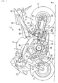
- reference numeral 1 generally denotes a motorcycle as an example of the vehicle.
- the motorcycle 1 has a front wheel 2 supported through a front axle to a front fork 3.
- the front fork 3 is steerably supported through a steering stem 4 to a head pipe 6 provided at the front end of a body frame 5.
- the body frame 5 includes a main frame 7 extending rearward from the head pipe 6 so as to be inclined downward.
- the rear end of the main frame 7 is bent downward and joined continuously to a pivot plate 8.
- the body frame 5 further includes a seat frame 9 extending rearward from a rear portion of the main frame 7 so as to be inclined upward.
- the front end of the seat frame 9 is connected to the rear portion of the main frame 7.
- a swing arm suspension 10 is provided at a rear portion of the vehicle body of the motorcycle 1.
- the swing arm suspension 10 has such a structure that the pivot plate 8 (vehicle body) is provided with a pivot shaft 11, a swing arm 13 having a rear end portion supporting a rear wheel (wheel) 12 is swingably mounted at a front end portion to the pivot shaft 11, and a cushion unit 14 is mounted at an upper end portion to the swing arm 13 and connected at a lower end portion through a link mechanism 15 to a portion of the pivot plate 8 lower in level than the pivot shaft 11.
- the pivot shaft 11 extends parallel to the lateral direction of the vehicle like an axle 16 for the rear wheel 12 (which axle will be hereinafter referred to as rear axle).
- a fuel tank 17 is mounted on the upper side of the main frame 7, and a water-cooled, in-line four-cylinder engine 18 is mounted on the lower side of the main frame 7.
- a rider seat 19 and a pillion seat 20 for a passenger are arranged in tandem on the rear side of the fuel tank 17.
- a rider step or footrest 21 is mounted on a rear portion of the pivot plate 8, and a pillion step or footrest 22 is mounted on a lower portion of the seat frame 9.
- a steering handle 23 is mounted at an upper end portion of the front fork 3.
- a brake caliper 24 is mounted at a lower end portion of the front fork 3, and a brake rotor 25 corresponding to the brake caliper 24 is mounted on the front wheel 2, thereby configuring a front brake unit 26.
- a rear brake unit having a configuration similar to that of the front brake unit 26 for the front wheel 2 is provided on the right side of the rear wheel 12.
- a front portion of the vehicle body of the motorcycle 1 is covered with a front cowl 27, and the periphery of the seat frame 9 is covered with a rear cowl 28.
- a rear sprocket 29 is mounted on the left side of the rear wheel 12, and a drive sprocket 30 is provided on the left side of a rear portion of the engine 18.
- a drive chain 31 is wrapped between the rear sprocket 29 and the drive sprocket 30 to thereby transmit a drive force of the engine 18 to the rear wheel 12.
- the engine 18 has a cylinder body 32 including four cylinders.
- a throttle body 33 corresponding to each cylinder is connected to a rear portion of the cylinder body 32.
- An air cleaner case 34 is located between the main frame 7 and the fuel tank 17, and is connected to all the throttle bodies 33.
- An exhaust pipe 35 corresponding to each cylinder is connected to a front portion of the cylinder body 32.
- a radiator 38 for cooling the engine 18 is provided on the front side of all the exhaust pipes 35.
- Each exhaust pipe 35 extends from the front wall portion of the cylinder body 32 so as to be curved downward. All the exhaust pipes 35 are joined together at a position below a crankcase 36 to provide a single exhaust pipe 35A.
- the exhaust pipe 35A is curved upward on the rear side of the pivot plate 8, and further curved rearward in the vicinity of the seat frame 9. Finally, the exhaust pipe 35A is connected to a silencer 37 supported to the seat frame 9. An exhaust control valve 39 is provided just downstream of a bent portion of the exhaust pipe 35A in the vicinity of the seat frame 9. The exhaust control valve 39 functions to change a flow area in the exhaust pipe 35A according to a rotational speed of the engine 18, thereby controlling exhaust pulsation in an exhaust system.
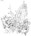
- an upper mount 40 is provided on an upper portion of the swing arm 13 at a position near the pivot shaft 11.
- the upper end portion of the cushion unit 14 is pivotably connected through a first connecting shaft 41 to the upper mount 40.
- a lower bracket 42 is provided on a lower portion of the swing arm 13 at a position on the rear side of the upper mount 40, and a link arm 43 of the link mechanism 15 is pivotably connected through a second connecting shaft 44 to the lower bracket 42.
- the link mechanism 15 includes the link arm 43 and a link rod 45 extending in the substantially longitudinal direction of the vehicle.
- the link arm 43 has a substantially triangular shape as viewed in side elevation, and each vertex portion of the link arm 43 serves as a connecting portion for another component. That is, an upper end portion of the link arm 43 is connected to the lower bracket 42. Further, a rear end portion of the link rod 45 is pivotably connected through a third connecting shaft 46 to a rear end portion of the link arm 43. Further, a body-sided lower bracket 47 is provided on the rear side of a lower end portion of the pivot plate 8, and a front end portion of the link rod 45 is pivotably connected through a fourth connecting shaft 48 to the body-sided lower bracket 47. Further, a lower end portion of the cushion unit 14 is pivotably connected through a fifth connecting shaft 49 to a front end portion of the link arm 43.
- the connecting shafts 41, 44, 46, 48, and 49 extend parallel to the pivot shaft 11.
- the link arm 43 connected through the link rod 45 to the vehicle body moves upward and pivots about the third connecting shaft 46 in a clockwise direction as viewed in FIG. 2, so that the lower end portion of the cushion unit 14 connected to the front end portion of the link arm 43 is moved upward.
- the stroke of the lower end portion of the cushion unit 14 is set larger than that (upward movement) of the upper end portion of the cushion unit 14 by the above swing of the swing arm 13, so that the cushion unit 14 is moved upward so as to decrease the distance between the upper and lower end portions of the cushion unit 14.
- the cushion unit 14 is moved downward so as to increase the distance between the upper and lower end portions of the cushion unit 14.
- the cushion unit 14 has an inverted damper 52 and a spring 53.
- the inverted damper 52 includes a cylinder 50 arranged on the upper side and a piston rod 51 arranged on the lower side.
- the piston rod 51 is moved with a piston accommodated in the cylinder 50.
- the spring 53 is set under a predetermined initial load between a flange portion formed at an upper end portion of the cylinder 50 and a flange portion formed at a lower end portion of the piston rod 51.
- a connecting portion (which will be hereinafter referred to as upper connecting portion) 54 for connection with the upper mount 40 is formed on the upper side of the cylinder 50, and a connecting portion (which will be hereinafter referred to as lower connecting portion) 55 for connection with the link arm 43 is formed on the lower side of the piston rod 51.
- These upper and lower connecting portions 54 and 55 are formed at the upper and lower end portions of the cushion unit 14, respectively. The cushion unit 14 is moved so that the distance between these upper and lower connecting portions 54 and 55 is decreased or increased, whereby shock or vibration from a road surface is changed to expansion and contraction of the spring 53, and is simultaneously reduced by expansion and contraction of the damper 52 to thereby gently absorb the shock or vibration.
- the upper end portion of the cushion unit 14 is mounted to the upper portion of the swing arm 13, and the lower end portion of the cushion unit 14 is mounted to the pivot plate 8 at a position lower than the pivot shaft 11. Accordingly, there is no possibility that a cushion load upon movement of the cushion unit 14 may be input to a portion of the vehicle body at a position higher than the pivot shaft 11. As a result, a cross pipe or the like can be removed from the body frame 5 as required in the case of mounting the cushion unit 14 to the vehicle body at a position higher than the pivot shaft 11. Accordingly, the exhaust pipe 35A including the exhaust control valve 39 and a relatively large component such as a battery (not shown) can be collectively located above the pivot shaft 11.
- An adjuster 56 for adjusting an extension damping force of the cushion unit 14 is integrally provided on the rear side of the upper end portion of the cylinder 50.
- the adjuster 56 projects from the rear side of the upper end portion of the cylinder 50 so as to be inclined upward toward the rear end of the vehicle with respect to an axis C of the cushion unit 14 extending in its longitudinal direction.
- a subtank 57 is integrally provided on the rear end of the adjuster 56 so as to communicate with the cylinder 50.
- a hydraulic oil or compressed gas, for example, is sealed in the subtank 57.
- the subtank 57 has a cylindrical shape, and it projects from the rear end of the adjuster 56 so as to be inclined upward toward the rear end of the vehicle with respect to the axis C.
- a lower adjuster 58 for adjusting a contraction damping force of the cushion unit 14 is integrally provided at the lower connecting portion 55.
- a rear fender 59 is mounted on an upper portion of the swing arm 13 at a position on the rear side of the upper mount 40.
- the rear fender 59 extends obliquely upward toward the rear end of the vehicle so as to cover the upper side of a front portion of the rear wheel 12.
- the swing arm suspension 10 shown in FIG. 2 is in a 1G condition (riding condition) where one occupant (rider or operator) rides on the vehicle.
- the rear axle 16 is at a level slightly lower than the pivot shaft 11.
- an arm axis M connecting the center of the pivot shaft 11 and the center of the rear axle 16 as viewed in side elevation is slightly inclined downward to the rear end.
- the cushion unit 14 is arranged so that the axis C of the cushion unit 14 is substantially perpendicular to the arm axis M.
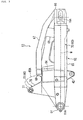
- the swing arm 13 includes a pivot pipe 61 rotatably supported through a needle bearing or the like to the pivot shaft 11, a pair of left and right arm portions 62 and 63 joined at their front ends to the opposite end portions of the pivot pipe 61 on their rear side, and a cross member 64 connecting the arm portions 62 and 63 at a position between the cushion unit 14 and the rear wheel 12.
- the rear wheel 12 is disposed between the arm portions 62 and 63 at their rear half portions, so that the space between the rear half portions of the arm portions 62 and 63 is set wider than that between the front half portions of the arm portions 62 and 63 where the base end portion of the swing arm 13 (on the pivot pipe 61 side) is formed.
- the right arm portion 63 is formed with a laterally inward curved recess 63a at a position near the pivot pipe 61, so as to avoid the interference with the exhaust pipe 35A passing the laterally outside area of the right arm portion 63.
- reference numeral 16A denotes an axis of the rear axle 16
- reference numeral 11A denotes an axis of the pivot shaft 11.
- the left arm portion 62 has a left arm body 65 extending along the arm axis M and formed from an aluminum extruded material, a left end piece 66 joined to the rear end of the left arm body 65 for supporting the rear axle 16, a subpipe 67 connected between the left end piece 66 and an upper portion of the cross member 64, and a rear stay 68 for connecting a rear portion of the subpipe 67 and a rear portion of the left arm body 65.
- the upper portion of the cross member 64 projects upward from the upper surface of the left arm body 65, and a connection wall 69 for connecting the front end of the subpipe 67 is vertically provided on the upper surface of the cross member 64 at a left rear portion thereof.
- the front end of the subpipe 67 is at a level higher than the upper surface of the cross member 64.
- the subpipe 67 extends obliquely rearward from the left side surface of the connection wall 69 so as to be curved to lie over the left arm body 65 as viewed in plan.
- the subpipe 67 extends rearward from the connection wall 69 in substantially parallel relationship with the left arm body 65, and is next bent obliquely downward to come into abutment against the upper surface of the left end piece 66.
- the rear end of the subpipe 67 is joined to the upper surface of the left end piece 66.
- the right arm portion 63 has a right arm body 70 formed by pressing an aluminum plate, and a right end piece 71 joined to the rear end of the right arm body 70 for supporting the rear axle 16.
- the right end piece 71 is symmetrical with the left end piece 66 like a mirror image.
- the right arm body 70 is wider than the left arm body 65 so that the upper surface of the right arm body 70 is substantially flush with the upper surface of the cross member 64.
- a through hole 72 is formed at an arbitrary position in the right arm body 70 to adjust a rigidity balance in the whole of the swing arm 13.
- the cross member 64 is an aluminum cast member, and it has a substantially vertically elongated rectangular cross section.
- the cross member 64 is connected between the two arm portions 62 and 63 (see FIGS. 3 and 5).
- the rear end of the cross member 64 is curved as viewed in plan so as to follow the shape of the outer circumference of the rear wheel 12.
- the front end portion of the cross member 64 extends at its laterally opposite positions near the left and right arm portions 62 and 63 toward the pivot pipe 61 so as to follow the laterally inside surfaces of the arm portions 62 and 63.
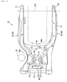
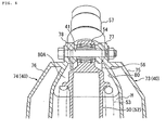
- Such left and right extended portions of the cross member 64 are integrally formed at their upper portions with a left mount member 73 and a right mount member 74. These left and right mount members 73 and 74 form a pair to configure the upper mount 40.
- the left and right mount members 73 and 74 respectively have left and right base portions 75 and 76 each having a substantially angular shape projecting upward as viewed in side elevation, and left and right boss portions 77 and 78 formed at the tops of the base portions 75 and 76 for allowing the insertion of the first connecting shaft 41.
- the base portions 75 and 76 are inclined laterally inward to their tops, and the upper connecting portion 54 of the cushion unit 14 is disposed between the opposed boss portions 77 and 78.
- the region surrounded by the pivot pipe 61, the front portions of the left and right arm portions 62 and 63, and the cross member 64 is formed as a cushion arrangement space H for arrangement of the cushion unit 14 (space for arrangement of the cushion unit).
- the upper mount 40 composed of the mount members 73 and 74 is formed so as to cover the upper side of the cushion arrangement space H.
- the rear portion of the upper mount 40 is formed with an opening 80 surrounded by the rear edges of the base portions 75 and 76 and the front edge of the upper portion of the cross member 64.
- This opening 80 makes the communication between the cushion arrangement space H of the swing arm 13 and an upper space K formed above the swing arm 13 between the rear fender 59 and the seat frame 9 as viewed in side elevation (see FIG. 2).
- An exposing portion 80A for exposing the cushion arrangement space H to the upper side of the swing arm 13 (a position just over the cross member 64) is provided on the rear side of the upper mount 40 in the longitudinal range defined between the rear portion of the upper mount 40 and the front end portion of the subpipe 67 and in the lateral range defined between the front portion of the left arm portion 62 and the front portion of the right arm portion 63.
- the adjuster 56 is located in the exposing portion 80A, and the subtank 57 connected thereto is located so as to project through the exposing portion 80A into the upper space K.
- the exposing portion 80A for locating or passing the adjuster 56 and the subtank 57 is ensured behind the upper mount 40.
- the lateral width of the adjuster 56 provided at the upper end portion of the cushion unit 14 is substantially the same as the outer diameter of the cylinder 50 of the damper 52, and the outer diameter of the subtank 57 is also substantially the same as the outer diameter of the cylinder 50. Further, the lateral width of the adjuster 56 and the outer diameter of the subtank 57 are larger than the lateral width of the upper connecting portion 54.
- the adjuster 56 and the subtank 57 connected together in tandem on the rear side of the upper end portion of the cylinder 50 are located in the exposing portion 80A provided behind the upper mount 40 through the opening 80, or located in the upper space K so as to pass the opening 80 (see FIG. 2). Referring also to FIG.
- the opening 80 is formed in the rear wall of the upper mount 40, which rear wall is inclined frontward to the upper side. Accordingly, the lateral width of the opening 80 is set larger at the rear lower position. With this configuration, the clearance between the swing arm 13 and the cushion unit 14 in the operation of the swing arm suspension 10 can be easily ensured.
- the swing arm suspension 10 has such a structure that the pivot plate 8 is provided with the pivot shaft 11, the swing arm 13 having a rear end portion supporting the rear wheel 12 is swingably mounted at a front end portion to the pivot shaft 11, and the cushion unit 14 is mounted at an upper end portion to the swing arm 13 and connected at a lower end portion through the link mechanism 15 to a portion of the pivot plate 8 lower in level than the pivot shaft 11.
- the upper portion of the swing arm 13 is provided with the exposing portion 80A for exposing the cushion arrangement space H to the upper space K above the swing arm 13, and the adjuster 56 as a functional component of the cushion unit 14 is located in the exposing portion 80A.
- the subtank 57 as another functional component of the cushion unit 14 is located in the upper space K.
- the exhaust pipe 35A and other components such as a battery can be collectively arranged, so that the cornering performance of the motorcycle 1 can be improved.
- the adjuster located in the exposing portion 80A or the subtank located in the upper space K can be formed integrally with the cushion unit 14. In this case, the number of parts can be reduced as compared with the case that the adjuster and the subtank are separate components to be fixed to the cushion unit. Accordingly, the swing arm suspension 10 can be easily assembled, and the weight and cost can also be reduced.
- the functional component of the cushion unit 14 projects from the upper portion of the cushion unit 14. With this configuration, any existing cushion unit can be used. In the case that the functional component of the cushion unit 14 projects into the upper space K above the swing arm 13, the space behind the upper mount 40 projecting upward from the upper portion of the swing arm 13 can be effectively utilized to rationalize the body design.
- the upper mount 40 for mounting the upper connecting portion 54 of the cushion unit 14 is formed integrally with the upper portion of the swing arm 13, and the exposing portion 80A is formed behind the upper mount 40. Accordingly, as compared with the case where the upper mount 40 is a separate member to be fixed to the swing arm 13, there is no need for using any fastening parts such as bolts for fastening the upper mount 40 to the swing arm 13 and for providing any fastening portions. As a result, the number of parts can be reduced, and the swing arm suspension 10 can be easily assembled. Further, the weight and cost can also be reduced.
- the exposing portion 80A for locating or passing the adjuster 56 and the subtank 57 is ensured behind the upper mount 40. Accordingly, this configuration is suitable especially in the motorcycle 1 having such a configuration that the exhaust pipe 35A extends from the lower side of the swing arm 13 toward the silencer 37 located above the swing arm 13.
- the present invention is not limited to the above preferred embodiment.
- only one of the adjuster 56 and the subtank 57 may be provided on the cushion unit 14.
- the subtank 57 may also be located in the exposing portion 80A.
- the rear portion of the engine 18 may be provided with a pivot shaft and a link mounting portion, and the swing arm 13 and the link mechanism 15 may be mounted on this pivot shaft and this link mounting portion, respectively.
- the swing arm 13 and the link mechanism 15 may be mounted on at least one of the body frame 5 (pivot plate 8) and the engine 18.
- the pivot plate 8 may be a separate member to be fixed to the body frame 5.
Landscapes
- Engineering & Computer Science (AREA)
- Mechanical Engineering (AREA)
- Axle Suspensions And Sidecars For Cycles (AREA)
- Vehicle Body Suspensions (AREA)
Applications Claiming Priority (2)
| Application Number | Priority Date | Filing Date | Title |
|---|---|---|---|
| JP2003317304A JP4130395B2 (ja) | 2003-09-09 | 2003-09-09 | スイングアーム式懸架装置 |
| JP2003317304 | 2003-09-09 |
Publications (2)
| Publication Number | Publication Date |
|---|---|
| EP1514787A1 EP1514787A1 (en) | 2005-03-16 |
| EP1514787B1 true EP1514787B1 (en) | 2006-03-15 |
Family
ID=34131976
Family Applications (1)
| Application Number | Title | Priority Date | Filing Date |
|---|---|---|---|
| EP04019199A Expired - Fee Related EP1514787B1 (en) | 2003-09-09 | 2004-08-12 | Swing arm suspension |
Country Status (9)
| Country | Link |
|---|---|
| US (1) | US7559566B2 (ja) |
| EP (1) | EP1514787B1 (ja) |
| JP (1) | JP4130395B2 (ja) |
| KR (1) | KR100558424B1 (ja) |
| CN (1) | CN100564148C (ja) |
| BR (1) | BRPI0403727B1 (ja) |
| DE (1) | DE602004000473T2 (ja) |
| MX (1) | MXPA04008525A (ja) |
| TW (1) | TWI245723B (ja) |
Families Citing this family (17)
| Publication number | Priority date | Publication date | Assignee | Title |
|---|---|---|---|---|
| US7472772B2 (en) * | 2003-02-20 | 2009-01-06 | Honda Motor Co., Ltd. | Structure for installing rear cushion |
| JP2007153254A (ja) * | 2005-12-08 | 2007-06-21 | Toyota Motor Corp | トレーリング・アーム式サスペンション構造 |
| JP4921801B2 (ja) * | 2006-02-01 | 2012-04-25 | 本田技研工業株式会社 | 二輪車の後輪懸架装置 |
| JP4928964B2 (ja) | 2007-01-30 | 2012-05-09 | 本田技研工業株式会社 | 車両のスイングアーム式懸架装置 |
| JP2009196410A (ja) * | 2008-02-19 | 2009-09-03 | Honda Motor Co Ltd | 自動二輪車 |
| JP5492491B2 (ja) | 2009-08-10 | 2014-05-14 | 本田技研工業株式会社 | 自動二輪車 |
| ES1072680Y (es) * | 2010-06-09 | 2010-12-28 | Creixell Jose Luis Belil | Motocicleta |
| JP5638133B2 (ja) * | 2011-05-31 | 2014-12-10 | 本田技研工業株式会社 | 自動二輪車 |
| US9238497B2 (en) * | 2011-12-28 | 2016-01-19 | Kawasaki Jukogyo Kabushiki Kaisha | Electric motorcycle |
| JP5964711B2 (ja) * | 2012-09-27 | 2016-08-03 | 本田技研工業株式会社 | 後輪懸架装置 |
| JP2014181007A (ja) * | 2013-03-21 | 2014-09-29 | Yamaha Motor Co Ltd | 自動二輪車 |
| JP6131787B2 (ja) * | 2013-09-03 | 2017-05-24 | トヨタ自動車株式会社 | 車両用サスペンションアーム |
| JP6009503B2 (ja) * | 2014-07-31 | 2016-10-19 | 本田技研工業株式会社 | 鞍乗り型車両のリンク機構保護構造 |
| CN106741520B (zh) * | 2016-01-29 | 2017-11-14 | 深圳市欣力通科技有限公司 | 三轮滑板车的后轮装配结构及三轮滑板车 |
| JP6492133B2 (ja) * | 2017-07-31 | 2019-03-27 | 本田技研工業株式会社 | 鞍乗型車両 |
| JP6913640B2 (ja) | 2018-01-25 | 2021-08-04 | 本田技研工業株式会社 | 鞍乗型車両のクッションコンロッド |
| TWI739394B (zh) * | 2020-04-16 | 2021-09-11 | 光陽工業股份有限公司 | 機車 |
Family Cites Families (8)
| Publication number | Priority date | Publication date | Assignee | Title |
|---|---|---|---|---|
| JPH0880887A (ja) * | 1994-09-13 | 1996-03-26 | Honda Motor Co Ltd | 自動2輪車の後輪懸架装置 |
| JP3773608B2 (ja) * | 1996-08-23 | 2006-05-10 | 本田技研工業株式会社 | 自動2輪車の車体構造 |
| JP4405001B2 (ja) * | 1999-08-31 | 2010-01-27 | 本田技研工業株式会社 | 自動二輪車におけるエンジン支持構造 |
| JP4364362B2 (ja) * | 1999-09-05 | 2009-11-18 | 本田技研工業株式会社 | 自動2輪車のフレーム構造 |
| JP3768788B2 (ja) | 2000-09-05 | 2006-04-19 | 本田技研工業株式会社 | 車両のスイングアーム式懸架装置 |
| JP3901954B2 (ja) * | 2001-04-04 | 2007-04-04 | 本田技研工業株式会社 | 自動二輪車のリヤサスペンション取付構造 |
| JP4627386B2 (ja) | 2001-07-03 | 2011-02-09 | 本田技研工業株式会社 | 自動二輪車のリヤサスペンション構造 |
| JP4108513B2 (ja) * | 2003-03-19 | 2008-06-25 | 本田技研工業株式会社 | ホイール構造及びホイール組付け方法 |
-
2003
- 2003-09-09 JP JP2003317304A patent/JP4130395B2/ja not_active Expired - Fee Related
-
2004
- 2004-08-12 DE DE602004000473T patent/DE602004000473T2/de active Active
- 2004-08-12 EP EP04019199A patent/EP1514787B1/en not_active Expired - Fee Related
- 2004-08-27 TW TW093125780A patent/TWI245723B/zh not_active IP Right Cessation
- 2004-09-02 BR BRPI0403727-8A patent/BRPI0403727B1/pt not_active IP Right Cessation
- 2004-09-03 KR KR1020040070436A patent/KR100558424B1/ko active IP Right Grant
- 2004-09-03 MX MXPA04008525A patent/MXPA04008525A/es active IP Right Grant
- 2004-09-03 US US10/933,395 patent/US7559566B2/en not_active Expired - Fee Related
- 2004-09-03 CN CNB2004100686027A patent/CN100564148C/zh not_active Expired - Fee Related
Also Published As
| Publication number | Publication date |
|---|---|
| MXPA04008525A (es) | 2005-03-10 |
| JP2005082040A (ja) | 2005-03-31 |
| KR100558424B1 (ko) | 2006-03-07 |
| TWI245723B (en) | 2005-12-21 |
| TW200516026A (en) | 2005-05-16 |
| EP1514787A1 (en) | 2005-03-16 |
| JP4130395B2 (ja) | 2008-08-06 |
| US7559566B2 (en) | 2009-07-14 |
| BRPI0403727A (pt) | 2005-05-03 |
| DE602004000473D1 (de) | 2006-05-11 |
| DE602004000473T2 (de) | 2006-10-05 |
| KR20050026339A (ko) | 2005-03-15 |
| CN1594020A (zh) | 2005-03-16 |
| US20050087947A1 (en) | 2005-04-28 |
| CN100564148C (zh) | 2009-12-02 |
| BRPI0403727B1 (pt) | 2015-05-26 |
Similar Documents
| Publication | Publication Date | Title |
|---|---|---|
| EP1514787B1 (en) | Swing arm suspension | |
| US7490688B2 (en) | Motorcycle frame | |
| EP1186526B1 (en) | Engine mounting structure in motorcycle | |
| EP1767446B1 (en) | Low floor type motorcycle | |
| JP4899625B2 (ja) | 鞍乗型不整地走行車両 | |
| EP2604498B1 (en) | Motorcycle brake pipe structure | |
| US7063179B2 (en) | Tricycle with a rocking mechanism | |
| US7621363B2 (en) | Body frame of motorcycle | |
| JP2019018758A (ja) | 鞍乗り型車両の前部構造 | |
| JP6122921B2 (ja) | 鞍乗り型車両 | |
| KR20020060605A (ko) | 자동 이륜차용 차체 프레임 구조 | |
| US10077092B2 (en) | Saddle-ride type vehicle | |
| EP3257733B1 (en) | Motorcycle | |
| JP4609950B2 (ja) | ヘッドライト装置 | |
| JPH0648362A (ja) | 自動二輪車におけるユニットスイング式エンジンの懸架構造 | |
| JP3643322B2 (ja) | 自動二輪車におけるユニットスイング式エンジンの懸架構造 | |
| US11535336B2 (en) | Saddle riding vehicle | |
| JP4129918B2 (ja) | リヤサスペンション | |
| US11305833B2 (en) | Saddle-riding-vehicle front part structure | |
| JP7354041B2 (ja) | クッション支持構造 | |
| EP1366977B1 (en) | Exhaust muffler layout structure in motorcycle |
Legal Events
| Date | Code | Title | Description |
|---|---|---|---|
| PUAI | Public reference made under article 153(3) epc to a published international application that has entered the european phase |
Free format text: ORIGINAL CODE: 0009012 |
|
| 17P | Request for examination filed |
Effective date: 20050119 |
|
| AK | Designated contracting states |
Kind code of ref document: A1 Designated state(s): AT BE BG CH CY CZ DE DK EE ES FI FR GB GR HU IE IT LI LU MC NL PL PT RO SE SI SK TR |
|
| AX | Request for extension of the european patent |
Extension state: AL HR LT LV MK |
|
| 17Q | First examination report despatched |
Effective date: 20050428 |
|
| GRAP | Despatch of communication of intention to grant a patent |
Free format text: ORIGINAL CODE: EPIDOSNIGR1 |
|
| AKX | Designation fees paid |
Designated state(s): DE FR GB |
|
| GRAS | Grant fee paid |
Free format text: ORIGINAL CODE: EPIDOSNIGR3 |
|
| GRAA | (expected) grant |
Free format text: ORIGINAL CODE: 0009210 |
|
| AK | Designated contracting states |
Kind code of ref document: B1 Designated state(s): DE FR GB |
|
| REG | Reference to a national code |
Ref country code: GB Ref legal event code: FG4D |
|
| REF | Corresponds to: |
Ref document number: 602004000473 Country of ref document: DE Date of ref document: 20060511 Kind code of ref document: P |
|
| ET | Fr: translation filed | ||
| PLBE | No opposition filed within time limit |
Free format text: ORIGINAL CODE: 0009261 |
|
| STAA | Information on the status of an ep patent application or granted ep patent |
Free format text: STATUS: NO OPPOSITION FILED WITHIN TIME LIMIT |
|
| 26N | No opposition filed |
Effective date: 20061218 |
|
| REG | Reference to a national code |
Ref country code: GB Ref legal event code: 746 Effective date: 20130520 |
|
| REG | Reference to a national code |
Ref country code: DE Ref legal event code: R084 Ref document number: 602004000473 Country of ref document: DE Effective date: 20130513 |
|
| REG | Reference to a national code |
Ref country code: FR Ref legal event code: PLFP Year of fee payment: 13 |
|
| REG | Reference to a national code |
Ref country code: FR Ref legal event code: PLFP Year of fee payment: 14 |
|
| REG | Reference to a national code |
Ref country code: FR Ref legal event code: PLFP Year of fee payment: 15 |
|
| PGFP | Annual fee paid to national office [announced via postgrant information from national office to epo] |
Ref country code: FR Payment date: 20190711 Year of fee payment: 16 |
|
| PGFP | Annual fee paid to national office [announced via postgrant information from national office to epo] |
Ref country code: GB Payment date: 20190814 Year of fee payment: 16 |
|
| GBPC | Gb: european patent ceased through non-payment of renewal fee |
Effective date: 20200812 |
|
| PG25 | Lapsed in a contracting state [announced via postgrant information from national office to epo] |
Ref country code: FR Free format text: LAPSE BECAUSE OF NON-PAYMENT OF DUE FEES Effective date: 20200831 |
|
| PG25 | Lapsed in a contracting state [announced via postgrant information from national office to epo] |
Ref country code: GB Free format text: LAPSE BECAUSE OF NON-PAYMENT OF DUE FEES Effective date: 20200812 |
|
| PGFP | Annual fee paid to national office [announced via postgrant information from national office to epo] |
Ref country code: DE Payment date: 20210630 Year of fee payment: 18 |
|
| REG | Reference to a national code |
Ref country code: DE Ref legal event code: R119 Ref document number: 602004000473 Country of ref document: DE |
|
| PG25 | Lapsed in a contracting state [announced via postgrant information from national office to epo] |
Ref country code: DE Free format text: LAPSE BECAUSE OF NON-PAYMENT OF DUE FEES Effective date: 20230301 |