EP1497217B1 - Vorrichtung zur betätigung und verriegelung von aufzugstüren mit mitnehmerkufen - Google Patents
Vorrichtung zur betätigung und verriegelung von aufzugstüren mit mitnehmerkufen Download PDFInfo
- Publication number
- EP1497217B1 EP1497217B1 EP03730187A EP03730187A EP1497217B1 EP 1497217 B1 EP1497217 B1 EP 1497217B1 EP 03730187 A EP03730187 A EP 03730187A EP 03730187 A EP03730187 A EP 03730187A EP 1497217 B1 EP1497217 B1 EP 1497217B1
- Authority
- EP
- European Patent Office
- Prior art keywords
- actuating
- door
- doors
- lever
- actuating lever
- Prior art date
- Legal status (The legal status is an assumption and is not a legal conclusion. Google has not performed a legal analysis and makes no representation as to the accuracy of the status listed.)
- Expired - Lifetime
Links
Images


Classifications
-
- B—PERFORMING OPERATIONS; TRANSPORTING
- B66—HOISTING; LIFTING; HAULING
- B66B—ELEVATORS; ESCALATORS OR MOVING WALKWAYS
- B66B13/00—Doors, gates, or other apparatus controlling access to, or exit from, cages or lift well landings
- B66B13/02—Door or gate operation
- B66B13/12—Arrangements for effecting simultaneous opening or closing of cage and landing doors
Definitions
- the invention relates to a device for operating and locking elevator doors with Mit increasinglykufen which are mounted on a car door and which are intended to operate shaft door drive rollers for actuating shaft doors, wherein an actuating device is provided to change the distance between the Mit recruitingkufen, the an actuating lever connected to a door drive, wherein the actuating lever is in operative connection with a first pivot lever, on which the Mit videkufen are hinged, and wherein a locking device is adapted to lock the car door.
- a device is e.g. from US-A-4,947,964.
- the doors of elevators are generally operated so that a door drive is provided on the elevator car, which performs the opening and closing movement of the car door.
- the shaft doors which are located at each breakpoint of the elevator, usually do not have their own door drive, but are carried along by entrainment devices of the car door.
- the driver device additionally has the task of performing the unlocking of the shaft doors.
- shaft door drive rollers are attached to the shaft doors, which have a certain distance in the horizontal direction.
- the entrainment device which is fastened to the door of the elevator car, has entrainment runners, which are oriented in the vertical direction and whose distance from one another is variable.
- the release of the unlocking the Shaft doors takes place in that the Mitauerkufen exert a force on the shaft door drive rollers. Basically, this force can compress the shaft door drive rollers or push apart.
- closing coupler or Sp Dr Drettippler are called closing coupler or Sp
- the car door opening movement can occur, with the force being transmitted from the car doors to the landing doors via the cam skids and shaft door drive rollers, so that the cab doors and shaft doors open simultaneously.
- the closing movement takes place in the reverse manner.
- the car doors themselves are often not completely locked, that is, they are locked in the closed state only by the force of the door drive.
- it is necessary or required by law to provide a locking of the car doors reliably preventing the car door from opening outside the so-called holding zones, that is, the intended stopping points of the elevator car.
- the lock must be designed so that the locking function is maintained even in the event of a power failure.
- it is necessary to release the locking in the holding zones be it in the normal and intended opening of the car door, be it in emergencies, for example, in case of power failure after manual lowering of the cabin.
- EP 0 709 334 A or EP 0 164 581 A locking devices have become known in which the lock is actuated by levers, which are connected to a cam follower and wherein the cam follower in the holding zones solid ramps is deflected from its rest position. In the rest position, the cabin doors are locked.
- a disadvantage of these solutions is that the adjustment effort for a plurality of ramps is relatively large.
- This probe element is each biased so that it has a distance from the Mit Collegekufe. Now, when the Mit videkufe presses against the shaft door drive roller in one floor, the probe element is pressed to the Mit constitutionalkufe, and this movement is utilized to unlock the car door. In EP 0 634 353 A the movement is transmitted via a cable, in EP 0 332 841 A via a control cam 24, which presses against a control roller 14.
- Object of the present invention is to develop the solutions described above so that on the one hand fixed ramps for actuating the car door lock can be avoided and on the other hand, a mechanically simple and inexpensive to produce actuation device can be realized.
- the actuating lever and the first pivot lever are pivotable about a predetermined angle to each other and that the locking device is connected to a tension element, which is hinged on the one hand to a Mitauerkufe and on the other hand on the actuating lever.
- the present invention is equally suitable for lock-to-lock as well as for split-type couplers and is readily adaptable to the various types of locking devices.
- the tension element can be designed as a pull rope, but it can also be used as a drawstring be represented, wherein as a material in addition to steel and suitable plastics o. The like. Can be selected.
- the tension element is firmly connected to a Mit Sprintfe and deflected by a deflection roller attached to the actuating lever. In this way, a particularly simple structure can be achieved.
- a structurally particularly favored design of the device is characterized in that a second pivot lever is provided which forms a parallelogram with the first pivot lever and the Mit Meetingkufen.
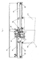
- FIG. 1 shows a general view of a device according to the invention in the installed position
- FIG. 2 shows the device of FIG. 1 on an enlarged scale in a position in which the door drive keeps the car door closed
- FIG. 3 shows a representation corresponding to FIG. 2 in a position of the device with failed door drive between floors while still locked cabin door
- Fig. 4 is a representation in which the lock is released in the floor area to open the car door.
- a door bracket 101 is provided in the form of a carrier.
- guide rails 102 are fixed, on which run rollers 103, where cabin doors 104a, 104b demographics are.
- the drive belt 106 is connected to an operating lever 1 of the device 100. Since the device 100 is directly connected to the first car door 104a, the first car door 104a is taken by the drive belt 106.
- the first cabin door 104a is further connected to a circulating cable 107, which is arranged substantially horizontally and is deflected by deflection rollers 108.
- the second car door 104b is also connected to the circulating cable 107, so that the opening and closing movement of the car doors 104a, 104b occur simultaneously and in opposite directions.
- shaft door drive rollers 109, 110 are shown, which are in communication with a shaft door 111 indicated here with broken lines.
- FIG. 2 shows a situation with closed car doors 104a, 104b and closed shaft doors 111.
- the entrainment runners 14, 15 of the device 100 are removed from the shaft door drive rollers 109, 110, so that the car is movable without affecting these shaft door drive rollers 109, 110.
- the opening movement of the doors 104, 104b; 111 is initiated by actuating the electric motor 105 and driving the drive belt 106.
- the actuating lever 1 is first actuated in the device 100, with the result that the Mitauerkufen 14, 15 are moved to each other.
- the Mitallekufen exert a compressive force on the shaft door drive rollers 109, 110, which solves a lock, not shown, the shaft doors 111.
- This position is shown in FIGS. 1 and 4.
- the entire device 100 by the drive belt 106 according to in Fig. 1 according to pulled left, whereby the opening movement of the first car door 104 a is initiated.
- the second car door 104b is moved in the opposite direction via the cable 107.
- the shaft doors 111 are taken and also opened.
- the operating lever 1 for the device 100 is connected to the drive belt 106 at a point of articulation 2.
- the actuating lever 1 is pivotally mounted about an axis 3 fixedly connected to the car door 104a.
- the drive belt 106 pulls the actuating lever 1 in the direction of arrow 4, so that an end of the actuating lever 1 is present at a firmly connected to the car door 104 a stop 5.
- a compression spring 6 exerts on a pull rod 7, a tensile force and thus biases the operating lever 1 via a pivot point 8 in a direction corresponding to a pivoting movement counter to the clockwise direction.
- a carrier strip 9 is further provided, which couples the pivotal movement of the driving lever 1 with a certain play with the pivoting movement of a first pivoting lever 10.
- the first pivot lever 10 forms with a similarly designed second pivot lever 11 and the two Mit psychologykufen 14, 15, which are connected to articulation points 12 with the pivot levers 10, 11, a Gelenkparallelogramm.
- the first pivot lever 10 is pivotable about the same axis 3 as the actuating lever 1.
- the second pivot lever 11 is pivotable about an axis 13 arranged below the axis 13.
- the Mit Conversekufen 14, 15 have the maximum distance d 0 , so that the shaft door drive rollers 109, 110, not shown here, 110 are not affected.
- the operating lever 1 is via a first and a second limiting lever 16, 17 are connected to a fixed axis 18, which limit levers 16, 17 are here in the position shown in a folded position.
- a pull cable 20 is attached as a tension element which is deflected about a guide roller 21 which is mounted on the actuating lever 1.
- the pull cable 20 is fixedly connected at point 23 to a latch 24 which is pivotally mounted about an axis 25. Before the point 23, the pull cable 20 is deflected by a further deflection roller 22 fixedly connected to the catch 24.
- a compression spring 26 biases the latch 24 counterclockwise.
- At the opposite end of the axis 25 of the latch 24 has a locking pin 28 which engages in the positions shown in Figs. 2 and 3 in a fixed locking latch 29 and thus the car door 104 a mechanically locked.
- the latch 24 further acts on a switch contact 27 which is designed to be able to detect and check the locking of the car doors 104a, 104b.
- a switch contact 27 which is designed to be able to detect and check the locking of the car doors 104a, 104b.
- a situation is shown in which the door drive has failed or by an error tries to open the car doors 104a, 104b outside a designated holding zone.
- the actuating lever 1 is here pivoted in the maximum possible position in the counterclockwise direction, which position is defined by the extended position of the limit levers 16, 17. In case of failed door drive this position is achieved by the force of the compression spring 6, which biases the operating lever 1 in the position shown.
- the pivot levers 10, 11 are also pivoted maximum in the counterclockwise direction and cause the Mitauerkufen 14, 15 occupy a position of maximum approximation, in their distance d is 1 .
- the position of the device shown in Fig. 4 corresponds to an intended opening of the car doors 104a, 104b.
- the actuating lever 1 is arranged by the drive belt as in Fig. 3 in the maximum possible direction of rotation counterclockwise.
- the movement of the Mitauerkufen 14, 15 is limited inwardly by the shaft door drive rollers 109, 110, so that a decency d 2 between the Mit psychologykufen 14, 15 sets, for the following applies: d 1 ⁇ d 2 ⁇ d 0
- the carrier strip 9 exerts a compressive force on the first pivot lever 10, wherein the game between the carrier strip 9 and the pivot lever 10 is utilized. Since in the position shown in Fig. 4, the movement of the Mit Conversekufen 14, 15 is limited inwardly, the distance between the pivot point 19 and the first guide roller 21, so that a tensile force is exerted on the pull cable 20, which is a movement causes the bolt 24 in the clockwise direction. By this movement, the locking pin 28 is disengaged from the locking catch 29 and the car door 104a released. Furthermore, the switching contact 27 is opened and thus interrupted the locking signal.
- FIG. 4 is achieved in the operative manner by actuating the door operator from the position of FIG. 2 in the holding zone can be, but also in an emergency from the position of Fig. 3, for example, if the cabin is mechanically lowered in case of power failure in the holding zone. In the latter case, the Mit Conversekufen 14, 15 of the shaft door drive rollers 109, 110 are pushed apart, which causes the unlocking of the car doors 104a, 104b to free any trapped persons in the cabin.
- the present invention makes it possible, with a minimum number of individual components, to realize a safe cabin door lock for elevators which corresponds to the given regulations.
Landscapes
- Elevator Door Apparatuses (AREA)
- Ladders (AREA)
Description
- Die Erfindung betrifft eine Vorrichtung zur Betätigung und Verriegelung von Aufzugstüren mit Mitnehmerkufen, die an einer Kabinentür gelagert sind und die dazu vorgesehen sind, Schachttürantriebsrollen zur Betätigung von Schachttüren zu betätigen, wobei eine Betätigungseinrichtung vorgesehen ist, um den Abstand zwischen den Mitnehmerkufen zu verändern, die einen mit einem Türantrieb verbundenen Betätigungshebel aufweist, wobei der Betätigungshebel mit einem ersten Schwenkhebel in Wirkverbindung steht, an dem die Mitnehmerkufen angelenkt sind, und wobei eine Verriegelungseinrichtung dazu ausgebildet ist, die Kabinentür zu verriegeln. Eine solche Vorrichtung ist z.B. aus US-A-4 947 964 bekannt.
- Die Türen von Aufzügen werden im Allgemeinen so betätigt, dass an der Aufzugskabine ein Türantrieb vorgesehen ist, der die Öffnungs- und Schließbewegung der Kabinentür ausführt. Die Schachttüren, die sich an jedem Haltepunkt des Aufzugs befinden, besitzen dabei üblicherweise keinen eigenen Türantrieb, sondern werden durch Mitnehmervorrichtungen von der Kabinentür mitgenommen. Die Mitnehmervorrichtung hat dabei zusätzlich die Aufgabe, die Entriegelung der Schachttüren durchzuführen.
- Üblicherweise sind an den Schachttüren Schachttürantriebsrollen befestigt, die in waagrechter Richtung einen bestimmten Abstand aufweisen. Die Mitnehmervorrichtung, die an der Tür der Aufzugskabine befestigt ist, besitzt Mitnehmerkufen, die in senkrechter Richtung orientiert sind und deren Abstand zueinander veränderbar ist. Das Lösen der Entriegelung der Schachttüren erfolgt dabei dadurch, dass die Mitnehmerkufen eine Kraft auf die Schachttürantriebsrollen ausüben. Grundsätzlich kann diese Kraft die Schachttürantriebsrollen zusammendrücken oder auseinander drücken. In der Praxis werden solche Systeme Schließkuppler bzw. Spreizkuppler genannt.
- Sobald die Entriegelung der Schachttüren erfolgt ist, kann die Öffnungsbewegung der Kabinentür erfolgen, wobei die Kraft von den Kabinentüren über die Mitnehmerkufen und die Schachttürantriebsrollen auch auf die Schachttüren übertragen wird, so dass die Kabinentüren und die Schachttüren gleichzeitig öffnen. Die Schließbewegung erfolgt in umgekehrter Weise.
- Die Kabinentüren selbst werden oftmals nicht vollständig verriegelt, das heißt, sie werden im geschlossenen Zustand lediglich durch die Kraft des Türantriebs zugehalten. Unter bestimmten Bedingungen ist es jedoch erforderlich oder gesetzlich vorgeschrieben, eine Verriegelung der Kabinentüren vorzusehen, die ein Öffnen der Kabinentür außerhalb der sogenannten Haltezonen, das sind die vorgesehenen Haltepunkte der Aufzugskabine, zuverlässig verhindern. Die Verriegelung muss dabei so ausgebildet sein, dass auch bei einem Stromausfall die Verriegelungsfunktion erhalten bleibt. Andererseits ist es jedoch erforderlich, in den Haltezonen die Verriegelung zu lösen, sei es bei der normalen und beabsichtigten Öffnung der Kabinentür, sei es in Notfällen beispielsweise bei Stromausfall nach manuellem Absenken der Kabine. Aus der EP 0 426 057 A, der EP 0 709 334 A oder der EP 0 164 581 A sind Verriegelungsvorrichtungen bekannt geworden, bei denen die Verriegelung über Hebel betätigt wird, die mit einer Abtastrolle in Verbindung stehen und wobei die Abtastrolle in den Haltezonen durch feste Rampen aus ihrer Ruhelage ausgelenkt wird. In der Ruhelage sind die Kabinentüren verriegelt. Nachteilig an diesen Lösungen ist, dass der Justierungsaufwand für eine Vielzahl von Rampen relativ groß ist.
- Aus der EP 0 744 373 A ist eine Lösung bekannt, bei der die Bewegung des Riegels der Schachttür auf den Riegel der Kabinentür übertragen wird. Die dazugehörige Mechanik weist viele Einzelteile auf.
- Um diese Nachteile zu vermeiden, sind Lösungen entwickelt worden, die die Verriegelungsvorrichtung für die Kabinentür mit der Bewegung der Mitnehmerkufen koppeln, so dass keine zusätzlichen Rampen in den Stockwerken erforderlich sind. Solche Lösungen sind beispielsweise in der US 6,173,815 B oder der EP 0 332 841 B beschrieben. Die Vorrichtungen sind dabei so aufgebaut, dass die Kabinentüren stets dann verriegelt sind, wenn der Türantrieb die Türen in die geschlossene Stellung drückt. Die Verriegelung bleibt jedoch auch dann aktiviert, wenn außerhalb eines Stockwerks der Türantrieb beispielsweise durch Stromausfall ausfällt oder durch einen Fehler unbeabsichtigterweise aktiviert wird und damit die Mitnehmerkufen in eine Stellung bewegt werden, die der Entriegelung der Schachttüren entspricht. Lediglich im Bereich der Haltezone in den jeweiligen Stockwerken kann eine Entriegelung der Kabinentür dadurch erfolgen, da die Mitnehmerkufen aktiviert werden, jedoch gegen die Schachttürantriebsrollen auflaufen und nicht ihre volle theoretisch mögliche Bewegung ausführen können. Bei den bekannten Lösungen wird diese Funktionalität über eine Reihe von Hebeln realisiert, die einerseits mit dem Türantrieb und andererseits mit einer Mitnehmerkufe verbunden sind. Die bekannten Lösungen sind mechanisch aufwendig und entsprechend kostspielig in der Herstellung und Instandhaltung. Beispiele dafür sind die EP 0 634 353 A und die gattungsbildende EP 0 332 841 A. An einer Mitnehmerkufe ist jeweils ein Tastelement angebracht (Wippe 3 bei der EP 0 634 353 A bzw. Auflaufkurve 5 bei der EP 0 332 841 A). Dieses Tastelement ist jeweils so vorgespannt, dass es einen Abstand von der Mitnehmerkufe hat. Wenn nun in einem Stockwerk die Mitnehmerkufe gegen die Schachttürantriebsrolle drückt, wird das Tastelement zur Mitnehmerkufe gedrückt, und diese Bewegung wird ausgenützt, um die Kabinentür zu entriegeln. Bei der EP 0 634 353 A wird die Bewegung über einen Seilzug übertragen, bei der EP 0 332 841 A über eine Steuerkurve 24, die gegen eine Steuerrolle 14 drückt.
- Aufgabe der vorliegenden Erfindung ist es, die oben beschriebenen Lösungen so weiterzubilden, dass einerseits feststehende Rampen zur Betätigung der Kabinentürverriegelung vermieden werden können und andererseits eine mechanisch einfache und kostengünstig herstellbare Betätigungsvorrichtung realisierbar ist.
- Erfindungsgemäß ist vorgesehen, dass der Betätigungshebel und der erste Schwenkhebel um einen vorgegebenen Winkel gegeneinander verschwenkbar sind und dass die Verriegelungseinrichtung mit einem Zugelement verbunden ist, das einerseits an einer Mitnehmerkufe und andererseits an dem Betätigungshebel angelenkt ist.
- Gemäß der Erfindung ist also kein zusätzliches Tastelement vorgesehen, sondern es wird einfach ein Spiel zwischen dem Betätigungshebel und dem ersten Schwenkhebel vorgesehen, sodass der Betätigungshebel und der erste Schwenkhebel um einen vorgegebenen Winkel gegeneinander verschwenkbar sind. Wenn nun die Mitnehmerkufen gegen die Schachttürantriebsrollen drücken, kommt es zu einer Relativbewegung zwischen Betätigungshebel und erstem Schwenkhebel. Diese wird von dem Zugelement, das sowohl an der Mitnehmerkufe als auch am Betätigungshebel angebracht ist, erfasst und auf die Verriegelungseinrichtung übertragen. Erfindungsgemäß kann also mit einer geringen Anzahl beweglicher Teile das Auslangen gefunden werden, so dass ein einfacher Aufbau und eine kostengünstige Herstellung möglich ist. Die vorliegende Erfindung ist in gleicher Weise für Schließkuppler wie für Spreizkuppler geeignet und ist leicht an die verschiedenen Arten von Verriegelungseinrichtungen anpassbar. Das Zugelement kann dabei als Zugseil ausgebildet sein, es kann jedoch auch als Zugband dargestellt werden, wobei als Material neben Stahl auch geeignete Kunststoffe o. dgl. gewählt werden können.
- In einer besonders begünstigten Ausführungsvariante ist das Zugelement fest mit einer Mitnehmerkufe verbunden und um eine am Betätigungshebel befestigte Umlenkrolle umgelenkt. Auf diese Weise kann ein besonders einfacher Aufbau erreicht werden.
- Ein konstruktiv besonders begünstigter Aufbau der Vorrichtung zeichnet sich dadurch aus, dass ein zweiter Schwenkhebel vorgesehen ist, der mit dem ersten Schwenkhebel und den Mitnehmerkufen eine Parallelogrammführung bildet.
- In der Folge wird die Erfindung anhand des in den Figuren dargestellten Ausführungsbeispiels näher erläutert.
- Es zeigen Fig. 1 eine allgemeine Ansicht einer erfindungsgemäßen Vorrichtung in der Einbauposition, Fig. 2 die Vorrichtung von Fig. 1 in vergrößertem Maßstab in einer Stellung, bei der der Türantrieb die Kabinentür geschlossen hält, Fig. 3 eine Darstellung entsprechend der Fig. 2 in einer Stellung der Vorrichtung bei ausgefallenem Türantrieb zwischen Stockwerken bei weiterhin verriegelter Kabinentür und Fig. 4 eine Darstellung, bei der die Verriegelung im Stockwerksbereich gelöst ist, um die Kabinentür zu öffnen.
- In Fig. 1 ist die erfindungsgemäße Vorrichtung 100 in ihrer Einbausituation dargestellt. Über der Einstiegsöffnung einer nicht näher dargestellten Aufzugskabine ist eine Türhalterung 101 in Form eines Trägers vorgesehen. An der Türhalterung 101 sind Führungsschienen 102 befestigt, auf denen Rollen 103 laufen, an denen Kabinentüren 104a, 104b aufgehänat sind. Die Betätigung der Kabinentüren 104a, 104b erfolgt über einen Elektromotor 105, der an der Türhalterung 101 befestigt ist und einen Antriebsriemen 106 antreibt. Der Antriebsriemen 106 ist mit einem Betätigungshebel 1 der Vorrichtung 100 verbunden. Da die Vorrichtung 100 direkt mit der ersten Kabinentür 104a verbunden ist, wird durch den Antriebsriemen 106 die erste Kabinentür 104a mitgenommen. Die erste Kabinentür 104a ist weiters mit einem umlaufenden Seil 107 verbunden, das im Wesentlichen waagrecht angeordnet ist und von Umlenkrollen 108 umgelenkt wird. Die zweite Kabinentür 104b ist ebenfalls mit dem umlaufenden Seil 107 verbunden, so dass die Öffnungs- und Schließbewegung der Kabinentüren 104a, 104b gleichzeitig und gegenläufig erfolgt. Weiters sind in der Fig. 1 zwischen den Mitnehmerkufen 14, 15 der Vorrichtung 100 Schachttürantriebsrollen 109, 110 dargestellt, die mit einer hier mit unterbrochenen Linien angedeuteten Schachttüre 111 in Verbindung stehen.
- Es wird nun kurz die an sich bekannte Funktion des Türantriebs beschrieben. In Fig. 2 ist eine Situation mit geschlossenen Kabinentüren 104a, 104b und geschlossenen Schachttüren 111 dargestellt. Die Mitnehmerkufen 14, 15 der Vorrichtung 100 sind von den Schachttürantriebsrollen 109, 110 entfernt, so dass die Kabine ohne Beeinflussung dieser Schachttürantriebsrollen 109, 110 beweglich ist. Die Öffnungsbewegung der Türen 104, 104b; 111 wird dadurch eingeleitet, dass der Elektromotor 105 betätigt wird und den Antriebsriemen 106 antreibt. Durch die Bewegung des Antriebsriemens 106 wird zunächst der Betätigungshebel 1 in der Vorrichtung 100 betätigt, was zur Folge hat, dass die Mitnehmerkufen 14, 15 zueinander bewegt werden. Die Mitnehmerkufen üben eine Druckkraft auf die Schachttürantriebsrollen 109, 110 aus, die eine nicht dargestellte Verriegelung der Schachttüren 111 löst. Diese Stellung ist in Fig. 1 und 4 dargestellt. Sobald der Betätigungshebel der Vorrichtung 100 an seinem Anschlag angelangt ist, wird die gesamte Vorrichtung 100 durch den Antriebsriemen 106 nach in Fig. 1 nach links gezogen, wodurch die Öffnungsbewegung der ersten Kabinentür 104a eingeleitet wird. Gleichzeitig wird über das Seil 107 die zweite Kabinentür 104b in der entegegengesetzten Richtung bewegt. Über die Schachttürantriebsrollen 109, 110 werden die Schachttüren 111 mitgenommen und ebenfalls geöffnet.
- Der Betätigungshebel 1 für die erfindungsgemäße Vorrichtung 100 ist an einem Anlenkpunkt 2 mit dem Antriebsriemen 106 verbunden. Der Betätigungshebel 1 ist um eine fest mit der Kabinentür 104a verbundene Achse 3 schwenkbar gelagert. In der in Fig. 2 dargestellten Stellung zieht der Antriebsriemen 106 den Betätigungshebel 1 in Richtung des Pfeils 4, so dass ein Ende Betätigungshebels 1 an einem fest mit der Kabinentür 104a verbundenen Anschlag 5 ansteht. Durch die Zugkraft des Antriebsriemens 106 wird die Kabinentür 104a gleichzeitig in der geschlossenen Stellung gehalten. Eine Druckfeder 6 übt auf eine Zugstange 7 eine Zugkraft aus und spannt damit den Betätigungshebel 1 über einen Anlenkpunkt 8 in eine Richtung vor, die einer Schwenkbewegung entgegen der Richtung des Uhrzeigersinns entspricht. An dem Betätigungshebel 1 ist weiters eine Mitnehmerleiste 9 vorgesehen, die die Schwenkbewegung des Mitnehmerhebels 1 mit einem gewissen Spiel mit der Schwenkbewegung eines ersten Schwenkhebels 10 koppelt. Der erste Schwenkhebel 10 bildet mit einem gleichartig ausgebildeten zweiten Schwenkhebel 11 und den beiden Mitnehmerkufen 14, 15, die an Anlenkpunkten 12 mit den Schwenkhebeln 10, 11 verbunden sind, ein Gelenkparallelogramm. Der erste Schwenkhebel 10 ist dabei um die gleiche Achse 3 schwenkbar wie der Betätigungshebel 1. Der zweite Schwenkhebel 11 ist um eine unterhalb der Achse 3 angeordnete Achse 13 schwenkbar.
- Es ist ersichtlich, dass in der in Fig. 2 dargestellten Stellung die Mitnehmerkufen 14, 15 den maximalen Abstand d0 aufweisen, so dass die hier nicht dargestellten Schachttürantriebsrollen 109, 110 nicht berührt werden. Der Betätigungshebel 1 ist über einen ersten und einen zweiten Begrenzungshebel 16, 17 mit einer festen Achse 18 verbunden, welche Begrenzungshebel 16, 17 hier sich in der gezeigten Stellung in einer ausgeknickten Position befinden.
- An der zweiten Mitnehmerkufe 15 ist im Punkt 19 ein Zugseil 20 als Zugelement befestigt, das um eine Umlenkrolle 21 umgelenkt ist, die am Betätigungshebel 1 angebracht ist. Das Zugseil 20 ist im Punkt 23 fest mit einem Riegel 24 verbunden, der um eine Achse 25 schwenkbar gelagert ist. Vor dem Punkt 23 ist das Zugseil 20 um eine fest mit dem Riegel 24 verbundene weitere Umlenkrolle 22 umgelenkt. Eine Druckfeder 26 spannt den Riegel 24 entgegen der Richtung des Uhrzeigersinns vor. An dem der Achse 25 gegenüberliegenden Ende besitzt der Riegel 24 einen Riegelzapfen 28, der in der in den Fig. 2 und 3 gezeigten Stellungen in eine feste Riegelraste 29 eingreift und damit die Kabinentür 104a mechanisch verriegelt.
- Der Riegel 24 wirkt weiters auf einen Schaltkontakt 27 ein, der dazu ausgebildet ist, um die Verriegelung der Kabinentüren 104a, 104b erfassen und überprüfen zu können. Dadurch ist es möglich, einer gegebenenfalls bestehenden Sicherheitsvorschrift genüge zu tun, die vorschreibt, dass eine Entriegelung der Kabinentür 104a, 104b einen sofortigen Stopp der Kabinenfahrt bewirken muss.
- In Fig. 3 ist eine Situation dargestellt, in der der Türantrieb ausgefallen ist oder durch einen Fehler versucht, die Kabinentüren 104a, 104b außerhalb einer vorgesehenen Haltezone zu öffnen. Der Betätigungshebel 1 ist hier in der maximal möglichen Stellung in der Richtung entgegen dem Uhrzeigersinn verschwenkt, welche Stellung durch die gestreckte Lage der Begrenzungshebel 16, 17 definiert ist. Bei ausgefallenem Türantrieb wird diese Stellung durch die Kraft der Druckfeder 6 erreicht, die den Betätigungshebel 1 in die gezeigte Stellung vorspannt. Die Schwenkhebel 10, 11 sind ebenfalls in der Richtung entgegen dem Uhrzeigersinn maximal verschwenkt und bewirken, dass die Mitnehmerkufen 14, 15 eine Stellung maximaler Annäherung einnehmen, in der ihr Abstand d1 beträgt. Aufgrund der geometrischen Verhältnisse im Zusammenhang mit dem Betätigungshebel 1, den Rollen 21, 22 und der Anlenkung im Punkt 19 wird auf das Zugseil 20 durch die Bewegung von der in Fig. 2 dargestellten Stellung in die in Fig. 3 dargestellte Stellung keine wesentliche Zugkraft auf das Zugseil 20 aufgebracht, so dass der Riegel 24 in der Verriegelungsposition verbleibt. Dies bedeutet, dass auch bei einem Stromausfall bzw. bei einem unbeabsichtigten Öffnungsversuch die Kabinentüren 104a, 104b verriegelt bleiben.
- Die Stellung von der Vorrichtung, die in Fig. 4 dargestellt ist, entspricht einer beabsichtigten Öffnung der Kabinentüren 104a, 104b. Der Betätigungshebel 1 ist dabei durch den Antriebsriemen wie in Fig. 3 in der maximal möglichen Drehrichtung entgegen dem Uhrzeigersinn angeordnet. Im Gegensatz zur Fig. 3 wird jedoch die Bewegung der Mitnehmerkufen 14, 15 nach innen durch die Schachttürantriebsrollen 109, 110 begrenzt, so dass sich ein Anstand d2 zwischen den Mitnehmerkufen 14, 15 einstellt, für den gilt:

- Die Mitnehmerleiste 9 übt dabei eine Druckkraft auf den ersten Schwenkhebel 10 aus, wobei das Spiel zwischen der Mitnehmerleiste 9 und dem Schwenkhebel 10 ausgenützt wird. Da in der in Fig. 4 gezeigten Stellung die Bewegung der Mitnehmerkufen 14, 15 nach innen hin begrenzt ist, vergrößert sich der Abstand zwischen dem Anlenkpunkt 19 und der ersten Umlenkrolle 21, so dass eine Zugkraft auf das Zugseil 20 ausgeübt wird, die eine Bewegung des Riegels 24 in Richtung des Uhrzeigersinns bewirkt. Durch diese Bewegung wird der Riegelzapfen 28 aus der Riegelraste 29 ausgerückt und die Kabinentür 104a freigegeben. Weiters wird auch der Schaltkontakt 27 geöffnet und damit das Verriegelungssignal unterbrochen.
- Es ist anzumerken, dass die Stellung von Fig. 4 sowohl in der betriebsmäßig vorgesehenen Weise durch Betätigung des Türantriebs aus der Stellung von Fig. 2 in der Haltezone erreicht werden kann, aber auch im Notfall aus der Stellung von Fig. 3, wenn z.B. die Kabine bei Stromausfall mechanisch in die Haltezone abgesenkt wird. In letzterem Fall werden die Mitnehmerkufen 14, 15 von den Schachttürantriebsrollen 109, 110 auseinandergedrückt, was die Entriegelung der Kabinentüren 104a, 104b bewirkt, um eventuell in der Kabine gefangene Personen befreien zu können.
- Die vorliegende Erfindung ermöglicht es, mit einer Mindestzahl an einzelnen Bauteilen eine sichere und den gegebenen Vorschriften entsprechende Kabinentürverriegelung für Aufzüge zu realisieren.
Claims (7)
- Vorrichtung zur Betätigung und Verriegelung von Aufzugstüren mit Mitnehmerkufen (14, 15), die an einer Kabinentür (104a, 104b) gelagert sind und die dazu vorgesehen sind, Schachttürantriebsrollen (109, 110) zur Betätigung von Schachttüren (111) zu betätigen, wobei eine Betätigungseinrichtung vorgesehen ist, um den Abstand (d0, d1, d2) zwischen den Mitnehmerkufen (14, 15) zu verändern, die einen mit einem Türantrieb verbundenen Betätigungshebel (1) aufweist, wobei der Betätigungshebel (1) mit einem ersten Schwenkhebel (10) in Wirkverbindung steht, an dem die Mitnehmerkufen (14, 15) angelenkt sind, und wobei eine Verriegelungseinrichtung dazu ausgebildet ist, die Kabinentür (104a, 104b) zu verriegeln, dadurch gekennzeichnet, dass der Betätigungshebel (1) und der erste Schwenkhebel (10) um einen vorgegebenen Winkel gegeneinander verschwenkbar sind und dass die Verriegelungseinrichtung mit einem Zugelement (20) verbunden ist, das einerseits an einer Mitnehmerkufe (15) und andererseits an dem Betätigungshebel (1) angelenkt ist.
- Vorrichtung nach Anspruch 1, dadurch gekennzeichnet, dass das Zugelement (20) fest mit einer Mitnehmerkufe (15) verbunden ist und um eine am Betätigungshebel (1) befestigte Umlenkrolle (21) umgelenkt ist.
- Vorrichtung nach einem der Ansprüche 1 oder 2, dadurch gekennzeichnet, dass die Verriegelungseinrichtung einen Riegel (24) umfasst, der mit dem Zugelement (20) verbunden ist und zur Überwachung der Verriegelung einen Schaltkontakt (27) schließt.
- Vorrichtung nach einem der Ansprüche 1 bis 3, dadurch gekennzeichnet, dass die Verriegelungseinrichtung einen Riegel (24) umfasst, der durch eine Druckfeder (26) in die Schließrichtung vorgespannt ist.
- Vorrichtung nach einem der Ansprüche 1 bis 4, dadurch gekennzeichnet, dass das Zugelement (20) als Zugseil ausgebildet ist.
- Vorrichtung nach einem der Ansprüche 1 bis 4, dadurch gekennzeichnet, dass das Zugelement (20) als Zugband ausgebildet ist.
- Vorrichtung nach einem der Ansprüche 1 bis 6, dadurch gekennzeichnet, dass ein zweiter Schwenkhebel (11) vorgesehen ist, der mit dem ersten Schwenkhebel (10) und den Mitnehmerkufen (14, 15) eine Parallelogrammführung bildet.
Applications Claiming Priority (3)
| Application Number | Priority Date | Filing Date | Title |
|---|---|---|---|
| AT0061902A AT412339B (de) | 2002-04-22 | 2002-04-22 | Vorrichtung zur betätigung und verriegelung von aufzugstüren mit mitnehmerkufen |
| AT6192002 | 2002-04-22 | ||
| PCT/EP2003/050116 WO2003089356A1 (de) | 2002-04-22 | 2003-04-17 | Vorrichtung zur betätigung und verriegelung von aufzugstüren mit mitnehmerkufen |
Publications (2)
| Publication Number | Publication Date |
|---|---|
| EP1497217A1 EP1497217A1 (de) | 2005-01-19 |
| EP1497217B1 true EP1497217B1 (de) | 2006-12-27 |
Family
ID=29220193
Family Applications (1)
| Application Number | Title | Priority Date | Filing Date |
|---|---|---|---|
| EP03730187A Expired - Lifetime EP1497217B1 (de) | 2002-04-22 | 2003-04-17 | Vorrichtung zur betätigung und verriegelung von aufzugstüren mit mitnehmerkufen |
Country Status (7)
| Country | Link |
|---|---|
| US (1) | US7252179B2 (de) |
| EP (1) | EP1497217B1 (de) |
| AT (2) | AT412339B (de) |
| AU (1) | AU2003240773A1 (de) |
| DE (1) | DE50306108D1 (de) |
| ES (1) | ES2276067T3 (de) |
| WO (1) | WO2003089356A1 (de) |
Families Citing this family (27)
| Publication number | Priority date | Publication date | Assignee | Title |
|---|---|---|---|---|
| JP4879477B2 (ja) * | 2003-12-08 | 2012-02-22 | インベンテイオ・アクテイエンゲゼルシヤフト | エレベータドア駆動装置 |
| AT413529B (de) * | 2004-02-11 | 2006-03-15 | Wittur Gmbh | Vorrichtung zur betätigung und verriegelung von aufzugstüren |
| EP1727762B1 (de) * | 2004-03-22 | 2008-03-05 | Otis Elevator Company | Mitnehmer für aufzugskabine- und schachttüren |
| US7254918B2 (en) * | 2004-11-12 | 2007-08-14 | Fahrzeugtechnik Dessau Ag | Emergency unlocking device for locking and unlocking systems for swinging sliding doors, in particular of rail vehicles |
| KR100828278B1 (ko) * | 2006-09-08 | 2008-05-07 | 오티스 엘리베이터 컴파니 | 엘리베이터 카 도어 및 랜딩 도어용 커플링 장치 |
| JP5403327B2 (ja) * | 2009-01-27 | 2014-01-29 | 富士電機株式会社 | 車両用引戸開閉装置 |
| EA020159B1 (ru) * | 2009-03-24 | 2014-09-30 | Сомюнг Ко., Лтд. | Запор двери |
| KR101034589B1 (ko) * | 2009-04-02 | 2011-05-11 | (주)보체스 | 전기식 도어 잠금장치 |
| ES2377631B1 (es) * | 2009-04-16 | 2013-02-05 | Klein Ibérica, S.A. | Dispositivo de desplazamiento simultáneo para puertas correderas. |
| CN102449253B (zh) * | 2009-05-26 | 2014-10-15 | 韩国产业银行 | 利用凸轮的电动门锁闭系统 |
| US9302886B2 (en) | 2010-05-17 | 2016-04-05 | Otis Elevator Company | Elevator door coupler assembly |
| EA017467B1 (ru) * | 2011-01-28 | 2012-12-28 | Руп Завод "Могилевлифтмаш" | Устройство для управления и блокировки двери кабины лифта |
| TWI447290B (zh) * | 2011-03-09 | 2014-08-01 | Nabtesco Corp | Attachment of the opening and closing device |
| CN105863407B (zh) * | 2011-03-10 | 2018-06-15 | 纳博特斯克有限公司 | 塞拉门装置 |
| WO2017016896A1 (de) * | 2015-07-30 | 2017-02-02 | Inventio Ag | Verriegelungssystem für kabinentüre |
| CN107848763B (zh) * | 2015-08-04 | 2021-06-11 | 奥的斯电梯公司 | 电梯轿厢门联锁装置 |
| KR102587893B1 (ko) | 2015-08-04 | 2023-10-11 | 오티스 엘리베이터 컴파니 | 실 로크를 갖는 카 도어 인터로크 |
| CN105731229B (zh) * | 2016-04-29 | 2017-09-08 | 展鹏科技股份有限公司 | 一体式轿门锁门刀装置 |
| EP3556708A1 (de) | 2018-04-19 | 2019-10-23 | Gomis Rabassa, Juan Ramón | System zum vorübergehenden koppeln einer stockwerkstür an eine kabinentür in einer aufzugsanlage mit schiebetüren |
| US11040852B2 (en) | 2018-05-01 | 2021-06-22 | Otis Elevator Company | Elevator car control to address abnormal passenger behavior |
| US11155444B2 (en) * | 2018-05-01 | 2021-10-26 | Otis Elevator Company | Elevator door interlock assembly |
| US11046557B2 (en) | 2018-05-01 | 2021-06-29 | Otis Elevator Company | Elevator door interlock assembly |
| US11034548B2 (en) | 2018-05-01 | 2021-06-15 | Otis Elevator Company | Elevator door interlock assembly |
| US11040858B2 (en) | 2018-05-01 | 2021-06-22 | Otis Elevator Company | Elevator door interlock assembly |
| US11254542B2 (en) | 2018-08-20 | 2022-02-22 | Otis Elevator Company | Car door interlock |
| US11247872B2 (en) | 2018-10-17 | 2022-02-15 | Otis Elevator Company | Elevator car door interlock |
| US11760604B1 (en) | 2022-05-27 | 2023-09-19 | Otis Elevator Company | Versatile elevator door interlock assembly |
Family Cites Families (9)
| Publication number | Priority date | Publication date | Assignee | Title |
|---|---|---|---|---|
| US3605952A (en) * | 1969-09-30 | 1971-09-20 | Otis Elevator Co | Door coupling apparatus for elevator systems |
| CH663406A5 (de) * | 1984-05-28 | 1987-12-15 | Inventio Ag | Tuerantriebsvorrichtung mit verriegelungsmechanismus fuer aufzuege. |
| ATE75458T1 (de) * | 1988-03-18 | 1992-05-15 | Inventio Ag | Tuerantriebsvorrichtung mit verriegelungsmechanismus fuer aufzuege. |
| FI85363C (fi) | 1989-10-30 | 1992-04-10 | Kone Oy | Laosningsanordning foer doerr i hisskorg. |
| DK0513509T3 (da) * | 1991-05-14 | 1996-03-18 | Inventio Ag | Elevator |
| US5377785A (en) * | 1993-07-12 | 1995-01-03 | Inventio Ag | Door closing system |
| FI96676C (fi) | 1994-10-31 | 1996-08-12 | Kone Oy | Hissin korinoven lukituslaitteisto ja menetelmä korinoven lukitsemiseksi ja vapauttamiseksi |
| DE29508499U1 (de) * | 1995-05-22 | 1996-09-26 | Meiller Fahrzeuge | Betätigungsvorrichtung für eine Aufzugtürkombination |
| US6173815B1 (en) * | 1997-02-28 | 2001-01-16 | Kone Corporation | Door coupler and locking device |
-
2002
- 2002-04-22 AT AT0061902A patent/AT412339B/de not_active IP Right Cessation
-
2003
- 2003-04-17 WO PCT/EP2003/050116 patent/WO2003089356A1/de active IP Right Grant
- 2003-04-17 AT AT03730187T patent/ATE349396T1/de not_active IP Right Cessation
- 2003-04-17 DE DE50306108T patent/DE50306108D1/de not_active Expired - Lifetime
- 2003-04-17 EP EP03730187A patent/EP1497217B1/de not_active Expired - Lifetime
- 2003-04-17 AU AU2003240773A patent/AU2003240773A1/en not_active Abandoned
- 2003-04-17 ES ES03730187T patent/ES2276067T3/es not_active Expired - Lifetime
- 2003-04-17 US US10/512,396 patent/US7252179B2/en not_active Expired - Lifetime
Also Published As
| Publication number | Publication date |
|---|---|
| ATA6192002A (de) | 2004-06-15 |
| WO2003089356A1 (de) | 2003-10-30 |
| DE50306108D1 (de) | 2007-02-08 |
| ES2276067T3 (es) | 2007-06-16 |
| EP1497217A1 (de) | 2005-01-19 |
| US7252179B2 (en) | 2007-08-07 |
| US20060174540A1 (en) | 2006-08-10 |
| AT412339B (de) | 2005-01-25 |
| ATE349396T1 (de) | 2007-01-15 |
| AU2003240773A1 (en) | 2003-11-03 |
Similar Documents
| Publication | Publication Date | Title |
|---|---|---|
| EP1497217B1 (de) | Vorrichtung zur betätigung und verriegelung von aufzugstüren mit mitnehmerkufen | |
| EP1713712B9 (de) | Vorrichtung zur betätigung und verriegelung von aufzugstüren | |
| EP1516847B1 (de) | Einrichtung zum Verbinden einer Kabinentür mit einer Schachttür und eine Einrichtung zur Notentriegelung einer Kabinentür | |
| EP0332841B1 (de) | Türantriebsvorrichtung mit Verriegelungsmechanismus für Aufzüge | |
| DE102009044832B4 (de) | Schloss für eine Gepäckbox | |
| EP2297018B1 (de) | Aufzugtürsystem mit kabinentürverriegelung | |
| DE3807067A1 (de) | Verriegelung fuer eine flugzeugtuer | |
| EP1914189B1 (de) | Verriegelungsmechanismus für die Tür einer Aufzugkabine | |
| EP0634353B1 (de) | Tür-Zuhalteeinrichtung | |
| DE10301325A1 (de) | Türverschluss mit Notentriegelung | |
| DE202006010217U1 (de) | Türverschluss | |
| DE69632957T2 (de) | Verfahren zur betätigung einer aufzugsschachttür und türkupplungsvorrichtung | |
| DE60207826T2 (de) | Türkupplungs- und -verriegelungsvorrichtung | |
| EP1187963A1 (de) | Sperrvorrichtung und damit versehene torantriebsvorrichtung für ein mittels eines motorantriebsaggregats antreibbares tor | |
| DE10113847A1 (de) | Sicherungsvorrichtung | |
| EP2576314B1 (de) | Verschluss für weichenstellvorrichtungen | |
| DE69629759T2 (de) | Betätigungsvorrichtung für ein Tor oder andere Verschlussplatte | |
| EP0716200A1 (de) | Verriegelungsvorrichtung für Türen | |
| EP0759496B1 (de) | Elektrischer Fensterheber | |
| DE2419995B2 (de) | Verriegelungsvorrichtung für eine Stockwerkstür eines Fahrstuhlschachtes | |
| EP3406832A1 (de) | Gegenkasten für ein paniktürschloss | |
| DE2042936A1 (de) | Schwenkschiebetuer fuer fahrzeuge. | |
| DE19957321B4 (de) | Betätigungsvorrichtung zum gemeinsamen Öffnen und Schließen einer Aufzugkabinentür und einer gegenüberstehenden Aufzugschachttür | |
| DE10202528A1 (de) | Mechanische Verriegelung für eine Fahrkorbschiebetür | |
| CH481836A (de) | Türbetätigungs- und -Verriegelungsvorrichtung an einer Aufzugsanlage |
Legal Events
| Date | Code | Title | Description |
|---|---|---|---|
| PUAI | Public reference made under article 153(3) epc to a published international application that has entered the european phase |
Free format text: ORIGINAL CODE: 0009012 |
|
| 17P | Request for examination filed |
Effective date: 20041008 |
|
| AK | Designated contracting states |
Kind code of ref document: A1 Designated state(s): AT BE BG CH CY CZ DE DK EE ES FI FR GB GR HU IE IT LI LU MC NL PT RO SE SI SK TR |
|
| AX | Request for extension of the european patent |
Extension state: AL LT LV MK |
|
| RIN1 | Information on inventor provided before grant (corrected) |
Inventor name: OBERLEITNER, RUPERT |
|
| GRAP | Despatch of communication of intention to grant a patent |
Free format text: ORIGINAL CODE: EPIDOSNIGR1 |
|
| GRAS | Grant fee paid |
Free format text: ORIGINAL CODE: EPIDOSNIGR3 |
|
| GRAA | (expected) grant |
Free format text: ORIGINAL CODE: 0009210 |
|
| RAP1 | Party data changed (applicant data changed or rights of an application transferred) |
Owner name: WITTUR AG |
|
| AK | Designated contracting states |
Kind code of ref document: B1 Designated state(s): AT BE BG CH CY CZ DE DK EE ES FI FR GB GR HU IE IT LI LU MC NL PT RO SE SI SK TR |
|
| PG25 | Lapsed in a contracting state [announced via postgrant information from national office to epo] |
Ref country code: DK Free format text: LAPSE BECAUSE OF FAILURE TO SUBMIT A TRANSLATION OF THE DESCRIPTION OR TO PAY THE FEE WITHIN THE PRESCRIBED TIME-LIMIT Effective date: 20061227 Ref country code: NL Free format text: LAPSE BECAUSE OF FAILURE TO SUBMIT A TRANSLATION OF THE DESCRIPTION OR TO PAY THE FEE WITHIN THE PRESCRIBED TIME-LIMIT Effective date: 20061227 Ref country code: CZ Free format text: LAPSE BECAUSE OF FAILURE TO SUBMIT A TRANSLATION OF THE DESCRIPTION OR TO PAY THE FEE WITHIN THE PRESCRIBED TIME-LIMIT Effective date: 20061227 Ref country code: SK Free format text: LAPSE BECAUSE OF FAILURE TO SUBMIT A TRANSLATION OF THE DESCRIPTION OR TO PAY THE FEE WITHIN THE PRESCRIBED TIME-LIMIT Effective date: 20061227 Ref country code: RO Free format text: LAPSE BECAUSE OF FAILURE TO SUBMIT A TRANSLATION OF THE DESCRIPTION OR TO PAY THE FEE WITHIN THE PRESCRIBED TIME-LIMIT Effective date: 20061227 Ref country code: IE Free format text: LAPSE BECAUSE OF FAILURE TO SUBMIT A TRANSLATION OF THE DESCRIPTION OR TO PAY THE FEE WITHIN THE PRESCRIBED TIME-LIMIT Effective date: 20061227 Ref country code: FI Free format text: LAPSE BECAUSE OF FAILURE TO SUBMIT A TRANSLATION OF THE DESCRIPTION OR TO PAY THE FEE WITHIN THE PRESCRIBED TIME-LIMIT Effective date: 20061227 Ref country code: SI Free format text: LAPSE BECAUSE OF FAILURE TO SUBMIT A TRANSLATION OF THE DESCRIPTION OR TO PAY THE FEE WITHIN THE PRESCRIBED TIME-LIMIT Effective date: 20061227 |
|
| REG | Reference to a national code |
Ref country code: GB Ref legal event code: FG4D Free format text: NOT ENGLISH |
|
| REG | Reference to a national code |
Ref country code: IE Ref legal event code: FG4D Free format text: LANGUAGE OF EP DOCUMENT: GERMAN |
|
| REF | Corresponds to: |
Ref document number: 50306108 Country of ref document: DE Date of ref document: 20070208 Kind code of ref document: P |
|
| REG | Reference to a national code |
Ref country code: GR Ref legal event code: EP Ref document number: 20070400291 Country of ref document: GR |
|
| PG25 | Lapsed in a contracting state [announced via postgrant information from national office to epo] |
Ref country code: BG Free format text: LAPSE BECAUSE OF FAILURE TO SUBMIT A TRANSLATION OF THE DESCRIPTION OR TO PAY THE FEE WITHIN THE PRESCRIBED TIME-LIMIT Effective date: 20070327 Ref country code: SE Free format text: LAPSE BECAUSE OF FAILURE TO SUBMIT A TRANSLATION OF THE DESCRIPTION OR TO PAY THE FEE WITHIN THE PRESCRIBED TIME-LIMIT Effective date: 20070327 |
|
| PG25 | Lapsed in a contracting state [announced via postgrant information from national office to epo] |
Ref country code: PT Free format text: LAPSE BECAUSE OF FAILURE TO SUBMIT A TRANSLATION OF THE DESCRIPTION OR TO PAY THE FEE WITHIN THE PRESCRIBED TIME-LIMIT Effective date: 20070528 |
|
| NLV1 | Nl: lapsed or annulled due to failure to fulfill the requirements of art. 29p and 29m of the patents act | ||
| REG | Reference to a national code |
Ref country code: ES Ref legal event code: FG2A Ref document number: 2276067 Country of ref document: ES Kind code of ref document: T3 |
|
| ET | Fr: translation filed | ||
| PLBE | No opposition filed within time limit |
Free format text: ORIGINAL CODE: 0009261 |
|
| STAA | Information on the status of an ep patent application or granted ep patent |
Free format text: STATUS: NO OPPOSITION FILED WITHIN TIME LIMIT |
|
| 26N | No opposition filed |
Effective date: 20070928 |
|
| REG | Reference to a national code |
Ref country code: CH Ref legal event code: PL |
|
| BERE | Be: lapsed |
Owner name: WITTUR A.G. Effective date: 20070430 |
|
| PG25 | Lapsed in a contracting state [announced via postgrant information from national office to epo] |
Ref country code: LI Free format text: LAPSE BECAUSE OF NON-PAYMENT OF DUE FEES Effective date: 20070430 Ref country code: CH Free format text: LAPSE BECAUSE OF NON-PAYMENT OF DUE FEES Effective date: 20070430 |
|
| PG25 | Lapsed in a contracting state [announced via postgrant information from national office to epo] |
Ref country code: BE Free format text: LAPSE BECAUSE OF NON-PAYMENT OF DUE FEES Effective date: 20070430 |
|
| PG25 | Lapsed in a contracting state [announced via postgrant information from national office to epo] |
Ref country code: AT Free format text: LAPSE BECAUSE OF NON-PAYMENT OF DUE FEES Effective date: 20070417 |
|
| PG25 | Lapsed in a contracting state [announced via postgrant information from national office to epo] |
Ref country code: EE Free format text: LAPSE BECAUSE OF FAILURE TO SUBMIT A TRANSLATION OF THE DESCRIPTION OR TO PAY THE FEE WITHIN THE PRESCRIBED TIME-LIMIT Effective date: 20061227 |
|
| PG25 | Lapsed in a contracting state [announced via postgrant information from national office to epo] |
Ref country code: MC Free format text: LAPSE BECAUSE OF NON-PAYMENT OF DUE FEES Effective date: 20070430 |
|
| PG25 | Lapsed in a contracting state [announced via postgrant information from national office to epo] |
Ref country code: CY Free format text: LAPSE BECAUSE OF FAILURE TO SUBMIT A TRANSLATION OF THE DESCRIPTION OR TO PAY THE FEE WITHIN THE PRESCRIBED TIME-LIMIT Effective date: 20061227 Ref country code: LU Free format text: LAPSE BECAUSE OF NON-PAYMENT OF DUE FEES Effective date: 20070417 |
|
| PG25 | Lapsed in a contracting state [announced via postgrant information from national office to epo] |
Ref country code: HU Free format text: LAPSE BECAUSE OF FAILURE TO SUBMIT A TRANSLATION OF THE DESCRIPTION OR TO PAY THE FEE WITHIN THE PRESCRIBED TIME-LIMIT Effective date: 20070628 |
|
| REG | Reference to a national code |
Ref country code: DE Ref legal event code: R082 Ref document number: 50306108 Country of ref document: DE Representative=s name: MISSELHORN, MARTIN, DIPL.-ING., DE |
|
| REG | Reference to a national code |
Ref country code: DE Ref legal event code: R082 Ref document number: 50306108 Country of ref document: DE Representative=s name: MISSELHORN, MARTIN, DIPL.-ING., DE Effective date: 20131114 Ref country code: DE Ref legal event code: R082 Ref document number: 50306108 Country of ref document: DE Representative=s name: MISSELHORN, MARTIN, DIPL.-ING., DE Effective date: 20130719 Ref country code: DE Ref legal event code: R081 Ref document number: 50306108 Country of ref document: DE Owner name: WITTUR HOLDING GMBH, DE Free format text: FORMER OWNER: WITTUR AG, 85259 WIEDENZHAUSEN, DE Effective date: 20131114 |
|
| REG | Reference to a national code |
Ref country code: FR Ref legal event code: PLFP Year of fee payment: 13 |
|
| REG | Reference to a national code |
Ref country code: FR Ref legal event code: PLFP Year of fee payment: 14 |
|
| REG | Reference to a national code |
Ref country code: FR Ref legal event code: PLFP Year of fee payment: 15 |
|
| REG | Reference to a national code |
Ref country code: FR Ref legal event code: PLFP Year of fee payment: 16 |
|
| PGFP | Annual fee paid to national office [announced via postgrant information from national office to epo] |
Ref country code: IT Payment date: 20220429 Year of fee payment: 20 Ref country code: GB Payment date: 20220425 Year of fee payment: 20 Ref country code: FR Payment date: 20220420 Year of fee payment: 20 Ref country code: ES Payment date: 20220518 Year of fee payment: 20 Ref country code: DE Payment date: 20220419 Year of fee payment: 20 |
|
| PGFP | Annual fee paid to national office [announced via postgrant information from national office to epo] |
Ref country code: TR Payment date: 20220412 Year of fee payment: 20 Ref country code: GR Payment date: 20220419 Year of fee payment: 20 |
|
| REG | Reference to a national code |
Ref country code: DE Ref legal event code: R071 Ref document number: 50306108 Country of ref document: DE |
|
| REG | Reference to a national code |
Ref country code: ES Ref legal event code: FD2A Effective date: 20230428 |
|
| REG | Reference to a national code |
Ref country code: GB Ref legal event code: PE20 Expiry date: 20230416 |
|
| PG25 | Lapsed in a contracting state [announced via postgrant information from national office to epo] |
Ref country code: ES Free format text: LAPSE BECAUSE OF EXPIRATION OF PROTECTION Effective date: 20230418 |
|
| PG25 | Lapsed in a contracting state [announced via postgrant information from national office to epo] |
Ref country code: GB Free format text: LAPSE BECAUSE OF EXPIRATION OF PROTECTION Effective date: 20230416 |