EP1481724A1 - Procédé de réaction en utilisant un microréacteur - Google Patents
Procédé de réaction en utilisant un microréacteur Download PDFInfo
- Publication number
- EP1481724A1 EP1481724A1 EP20040012710 EP04012710A EP1481724A1 EP 1481724 A1 EP1481724 A1 EP 1481724A1 EP 20040012710 EP20040012710 EP 20040012710 EP 04012710 A EP04012710 A EP 04012710A EP 1481724 A1 EP1481724 A1 EP 1481724A1
- Authority
- EP
- European Patent Office
- Prior art keywords
- reaction
- fluids
- fluid
- participating
- microreactor
- Prior art date
- Legal status (The legal status is an assumption and is not a legal conclusion. Google has not performed a legal analysis and makes no representation as to the accuracy of the status listed.)
- Withdrawn
Links
- 238000006243 chemical reaction Methods 0.000 title claims abstract description 357
- 238000000034 method Methods 0.000 title claims description 40
- 239000012530 fluid Substances 0.000 claims abstract description 405
- 238000004891 communication Methods 0.000 claims abstract description 6
- 239000007795 chemical reaction product Substances 0.000 claims description 25
- 238000000605 extraction Methods 0.000 claims description 17
- 230000003247 decreasing effect Effects 0.000 claims description 10
- 239000002904 solvent Substances 0.000 claims description 6
- 230000008602 contraction Effects 0.000 description 15
- 238000005192 partition Methods 0.000 description 15
- 230000001105 regulatory effect Effects 0.000 description 15
- 239000007788 liquid Substances 0.000 description 13
- 238000009792 diffusion process Methods 0.000 description 11
- SQGYOTSLMSWVJD-UHFFFAOYSA-N silver(1+) nitrate Chemical compound [Ag+].[O-]N(=O)=O SQGYOTSLMSWVJD-UHFFFAOYSA-N 0.000 description 11
- RFFLAFLAYFXFSW-UHFFFAOYSA-N 1,2-dichlorobenzene Chemical compound ClC1=CC=CC=C1Cl RFFLAFLAYFXFSW-UHFFFAOYSA-N 0.000 description 9
- 239000010419 fine particle Substances 0.000 description 9
- 239000002244 precipitate Substances 0.000 description 9
- 125000006850 spacer group Chemical group 0.000 description 9
- FAPWRFPIFSIZLT-UHFFFAOYSA-M Sodium chloride Chemical compound [Na+].[Cl-] FAPWRFPIFSIZLT-UHFFFAOYSA-M 0.000 description 8
- 238000004519 manufacturing process Methods 0.000 description 8
- 239000000126 substance Substances 0.000 description 8
- XLYOFNOQVPJJNP-UHFFFAOYSA-N water Substances O XLYOFNOQVPJJNP-UHFFFAOYSA-N 0.000 description 8
- 239000007789 gas Substances 0.000 description 7
- 238000002156 mixing Methods 0.000 description 7
- 238000010438 heat treatment Methods 0.000 description 6
- 239000000047 product Substances 0.000 description 6
- 239000012153 distilled water Substances 0.000 description 5
- 230000000694 effects Effects 0.000 description 5
- 238000012986 modification Methods 0.000 description 5
- 230000004048 modification Effects 0.000 description 5
- 239000007864 aqueous solution Substances 0.000 description 4
- 230000015572 biosynthetic process Effects 0.000 description 4
- 238000004140 cleaning Methods 0.000 description 4
- 239000011248 coating agent Substances 0.000 description 4
- 230000000052 comparative effect Effects 0.000 description 4
- 238000003780 insertion Methods 0.000 description 4
- 230000037431 insertion Effects 0.000 description 4
- 239000000463 material Substances 0.000 description 4
- 239000000203 mixture Substances 0.000 description 4
- 230000002093 peripheral effect Effects 0.000 description 4
- 229910001961 silver nitrate Inorganic materials 0.000 description 4
- 239000011780 sodium chloride Substances 0.000 description 4
- 239000000243 solution Substances 0.000 description 4
- 239000010935 stainless steel Substances 0.000 description 4
- 229910001220 stainless steel Inorganic materials 0.000 description 4
- YCKRFDGAMUMZLT-UHFFFAOYSA-N Fluorine atom Chemical compound [F] YCKRFDGAMUMZLT-UHFFFAOYSA-N 0.000 description 3
- XUIMIQQOPSSXEZ-UHFFFAOYSA-N Silicon Chemical compound [Si] XUIMIQQOPSSXEZ-UHFFFAOYSA-N 0.000 description 3
- HEMHJVSKTPXQMS-UHFFFAOYSA-M Sodium hydroxide Chemical compound [OH-].[Na+] HEMHJVSKTPXQMS-UHFFFAOYSA-M 0.000 description 3
- 238000005345 coagulation Methods 0.000 description 3
- 230000015271 coagulation Effects 0.000 description 3
- 239000011737 fluorine Substances 0.000 description 3
- 229910052731 fluorine Inorganic materials 0.000 description 3
- 229940127554 medical product Drugs 0.000 description 3
- 230000035484 reaction time Effects 0.000 description 3
- 238000000926 separation method Methods 0.000 description 3
- 239000010703 silicon Substances 0.000 description 3
- 229910052710 silicon Inorganic materials 0.000 description 3
- HKZLPVFGJNLROG-UHFFFAOYSA-M silver monochloride Chemical compound [Cl-].[Ag+] HKZLPVFGJNLROG-UHFFFAOYSA-M 0.000 description 3
- IJGRMHOSHXDMSA-UHFFFAOYSA-N Atomic nitrogen Chemical compound N#N IJGRMHOSHXDMSA-UHFFFAOYSA-N 0.000 description 2
- XEEYBQQBJWHFJM-UHFFFAOYSA-N Iron Chemical compound [Fe] XEEYBQQBJWHFJM-UHFFFAOYSA-N 0.000 description 2
- DKGAVHZHDRPRBM-UHFFFAOYSA-N Tert-Butanol Chemical compound CC(C)(C)O DKGAVHZHDRPRBM-UHFFFAOYSA-N 0.000 description 2
- 150000001875 compounds Chemical class 0.000 description 2
- 238000010276 construction Methods 0.000 description 2
- 235000014113 dietary fatty acids Nutrition 0.000 description 2
- UKMSUNONTOPOIO-UHFFFAOYSA-N docosanoic acid Chemical compound CCCCCCCCCCCCCCCCCCCCCC(O)=O UKMSUNONTOPOIO-UHFFFAOYSA-N 0.000 description 2
- 238000004299 exfoliation Methods 0.000 description 2
- 238000002474 experimental method Methods 0.000 description 2
- 239000000194 fatty acid Substances 0.000 description 2
- 229930195729 fatty acid Natural products 0.000 description 2
- 150000004665 fatty acids Chemical class 0.000 description 2
- 238000000265 homogenisation Methods 0.000 description 2
- 238000011031 large-scale manufacturing process Methods 0.000 description 2
- 239000003921 oil Substances 0.000 description 2
- 239000012860 organic pigment Substances 0.000 description 2
- 238000001556 precipitation Methods 0.000 description 2
- 230000002265 prevention Effects 0.000 description 2
- GGCZERPQGJTIQP-UHFFFAOYSA-N sodium;9,10-dioxoanthracene-2-sulfonic acid Chemical compound [Na+].C1=CC=C2C(=O)C3=CC(S(=O)(=O)O)=CC=C3C(=O)C2=C1 GGCZERPQGJTIQP-UHFFFAOYSA-N 0.000 description 2
- 238000003756 stirring Methods 0.000 description 2
- 238000003786 synthesis reaction Methods 0.000 description 2
- 239000004925 Acrylic resin Substances 0.000 description 1
- 229920000178 Acrylic resin Polymers 0.000 description 1
- 235000021357 Behenic acid Nutrition 0.000 description 1
- 108010010803 Gelatin Proteins 0.000 description 1
- DGAQECJNVWCQMB-PUAWFVPOSA-M Ilexoside XXIX Chemical compound C[C@@H]1CC[C@@]2(CC[C@@]3(C(=CC[C@H]4[C@]3(CC[C@@H]5[C@@]4(CC[C@@H](C5(C)C)OS(=O)(=O)[O-])C)C)[C@@H]2[C@]1(C)O)C)C(=O)O[C@H]6[C@@H]([C@H]([C@@H]([C@H](O6)CO)O)O)O.[Na+] DGAQECJNVWCQMB-PUAWFVPOSA-M 0.000 description 1
- BQCADISMDOOEFD-UHFFFAOYSA-N Silver Chemical compound [Ag] BQCADISMDOOEFD-UHFFFAOYSA-N 0.000 description 1
- RTAQQCXQSZGOHL-UHFFFAOYSA-N Titanium Chemical compound [Ti] RTAQQCXQSZGOHL-UHFFFAOYSA-N 0.000 description 1
- 239000000956 alloy Substances 0.000 description 1
- 229910045601 alloy Inorganic materials 0.000 description 1
- 229910052782 aluminium Inorganic materials 0.000 description 1
- XAGFODPZIPBFFR-UHFFFAOYSA-N aluminium Chemical compound [Al] XAGFODPZIPBFFR-UHFFFAOYSA-N 0.000 description 1
- 229940116226 behenic acid Drugs 0.000 description 1
- 230000000903 blocking effect Effects 0.000 description 1
- 239000003054 catalyst Substances 0.000 description 1
- 238000006555 catalytic reaction Methods 0.000 description 1
- 239000012295 chemical reaction liquid Substances 0.000 description 1
- 239000003153 chemical reaction reagent Substances 0.000 description 1
- 238000000576 coating method Methods 0.000 description 1
- 239000000084 colloidal system Substances 0.000 description 1
- 230000001276 controlling effect Effects 0.000 description 1
- 239000002826 coolant Substances 0.000 description 1
- 230000007797 corrosion Effects 0.000 description 1
- 238000005260 corrosion Methods 0.000 description 1
- 230000007547 defect Effects 0.000 description 1
- 238000011161 development Methods 0.000 description 1
- 239000006185 dispersion Substances 0.000 description 1
- 238000006073 displacement reaction Methods 0.000 description 1
- KQBYNGJTZNCQCO-UHFFFAOYSA-N ethyl 4-fluoro-3-oxobutanoate Chemical compound CCOC(=O)CC(=O)CF KQBYNGJTZNCQCO-UHFFFAOYSA-N 0.000 description 1
- XYIBRDXRRQCHLP-UHFFFAOYSA-N ethyl acetoacetate Chemical compound CCOC(=O)CC(C)=O XYIBRDXRRQCHLP-UHFFFAOYSA-N 0.000 description 1
- 239000000284 extract Substances 0.000 description 1
- 238000003682 fluorination reaction Methods 0.000 description 1
- 229920002313 fluoropolymer Polymers 0.000 description 1
- 229920000159 gelatin Polymers 0.000 description 1
- 239000008273 gelatin Substances 0.000 description 1
- 235000019322 gelatine Nutrition 0.000 description 1
- 235000011852 gelatine desserts Nutrition 0.000 description 1
- 239000011521 glass Substances 0.000 description 1
- 230000005484 gravity Effects 0.000 description 1
- 238000011835 investigation Methods 0.000 description 1
- 229910052742 iron Inorganic materials 0.000 description 1
- 238000003475 lamination Methods 0.000 description 1
- 238000004811 liquid chromatography Methods 0.000 description 1
- 229910052751 metal Inorganic materials 0.000 description 1
- 239000002184 metal Substances 0.000 description 1
- 239000007769 metal material Substances 0.000 description 1
- 238000003541 multi-stage reaction Methods 0.000 description 1
- 229910052757 nitrogen Inorganic materials 0.000 description 1
- 229960004624 perflexane Drugs 0.000 description 1
- ZJIJAJXFLBMLCK-UHFFFAOYSA-N perfluorohexane Chemical compound FC(F)(F)C(F)(F)C(F)(F)C(F)(F)C(F)(F)C(F)(F)F ZJIJAJXFLBMLCK-UHFFFAOYSA-N 0.000 description 1
- 239000000049 pigment Substances 0.000 description 1
- 229920003229 poly(methyl methacrylate) Polymers 0.000 description 1
- 238000006116 polymerization reaction Methods 0.000 description 1
- 239000004926 polymethyl methacrylate Substances 0.000 description 1
- 230000001737 promoting effect Effects 0.000 description 1
- 230000001681 protective effect Effects 0.000 description 1
- 238000007348 radical reaction Methods 0.000 description 1
- 238000006479 redox reaction Methods 0.000 description 1
- 239000011347 resin Substances 0.000 description 1
- 229920005989 resin Polymers 0.000 description 1
- 229910052709 silver Inorganic materials 0.000 description 1
- 239000004332 silver Substances 0.000 description 1
- KKKDGYXNGYJJRX-UHFFFAOYSA-M silver nitrite Chemical compound [Ag+].[O-]N=O KKKDGYXNGYJJRX-UHFFFAOYSA-M 0.000 description 1
- 229910052708 sodium Inorganic materials 0.000 description 1
- 239000011734 sodium Substances 0.000 description 1
- 238000004381 surface treatment Methods 0.000 description 1
- 239000000725 suspension Substances 0.000 description 1
- 239000010936 titanium Substances 0.000 description 1
- 229910052719 titanium Inorganic materials 0.000 description 1
- 238000011144 upstream manufacturing Methods 0.000 description 1
Images


Classifications
-
- B—PERFORMING OPERATIONS; TRANSPORTING
- B01—PHYSICAL OR CHEMICAL PROCESSES OR APPARATUS IN GENERAL
- B01F—MIXING, e.g. DISSOLVING, EMULSIFYING OR DISPERSING
- B01F25/00—Flow mixers; Mixers for falling materials, e.g. solid particles
- B01F25/30—Injector mixers
- B01F25/31—Injector mixers in conduits or tubes through which the main component flows
- B01F25/313—Injector mixers in conduits or tubes through which the main component flows wherein additional components are introduced in the centre of the conduit
- B01F25/3132—Injector mixers in conduits or tubes through which the main component flows wherein additional components are introduced in the centre of the conduit by using two or more injector devices
- B01F25/31324—Injector mixers in conduits or tubes through which the main component flows wherein additional components are introduced in the centre of the conduit by using two or more injector devices arranged concentrically
-
- B—PERFORMING OPERATIONS; TRANSPORTING
- B01—PHYSICAL OR CHEMICAL PROCESSES OR APPARATUS IN GENERAL
- B01F—MIXING, e.g. DISSOLVING, EMULSIFYING OR DISPERSING
- B01F33/00—Other mixers; Mixing plants; Combinations of mixers
- B01F33/30—Micromixers
- B01F33/301—Micromixers using specific means for arranging the streams to be mixed, e.g. channel geometries or dispositions
- B01F33/3011—Micromixers using specific means for arranging the streams to be mixed, e.g. channel geometries or dispositions using a sheathing stream of a fluid surrounding a central stream of a different fluid, e.g. for reducing the cross-section of the central stream or to produce droplets from the central stream
-
- B—PERFORMING OPERATIONS; TRANSPORTING
- B01—PHYSICAL OR CHEMICAL PROCESSES OR APPARATUS IN GENERAL
- B01F—MIXING, e.g. DISSOLVING, EMULSIFYING OR DISPERSING
- B01F33/00—Other mixers; Mixing plants; Combinations of mixers
- B01F33/30—Micromixers
- B01F33/301—Micromixers using specific means for arranging the streams to be mixed, e.g. channel geometries or dispositions
- B01F33/3012—Interdigital streams, e.g. lamellae
-
- B—PERFORMING OPERATIONS; TRANSPORTING
- B01—PHYSICAL OR CHEMICAL PROCESSES OR APPARATUS IN GENERAL
- B01J—CHEMICAL OR PHYSICAL PROCESSES, e.g. CATALYSIS OR COLLOID CHEMISTRY; THEIR RELEVANT APPARATUS
- B01J19/00—Chemical, physical or physico-chemical processes in general; Their relevant apparatus
- B01J19/0093—Microreactors, e.g. miniaturised or microfabricated reactors
-
- B—PERFORMING OPERATIONS; TRANSPORTING
- B01—PHYSICAL OR CHEMICAL PROCESSES OR APPARATUS IN GENERAL
- B01J—CHEMICAL OR PHYSICAL PROCESSES, e.g. CATALYSIS OR COLLOID CHEMISTRY; THEIR RELEVANT APPARATUS
- B01J2219/00—Chemical, physical or physico-chemical processes in general; Their relevant apparatus
- B01J2219/00781—Aspects relating to microreactors
- B01J2219/00788—Three-dimensional assemblies, i.e. the reactor comprising a form other than a stack of plates
-
- G—PHYSICS
- G03—PHOTOGRAPHY; CINEMATOGRAPHY; ANALOGOUS TECHNIQUES USING WAVES OTHER THAN OPTICAL WAVES; ELECTROGRAPHY; HOLOGRAPHY
- G03C—PHOTOSENSITIVE MATERIALS FOR PHOTOGRAPHIC PURPOSES; PHOTOGRAPHIC PROCESSES, e.g. CINE, X-RAY, COLOUR, STEREO-PHOTOGRAPHIC PROCESSES; AUXILIARY PROCESSES IN PHOTOGRAPHY
- G03C1/00—Photosensitive materials
- G03C1/005—Silver halide emulsions; Preparation thereof; Physical treatment thereof; Incorporation of additives therein
- G03C1/015—Apparatus or processes for the preparation of emulsions
-
- G—PHYSICS
- G03—PHOTOGRAPHY; CINEMATOGRAPHY; ANALOGOUS TECHNIQUES USING WAVES OTHER THAN OPTICAL WAVES; ELECTROGRAPHY; HOLOGRAPHY
- G03C—PHOTOSENSITIVE MATERIALS FOR PHOTOGRAPHIC PURPOSES; PHOTOGRAPHIC PROCESSES, e.g. CINE, X-RAY, COLOUR, STEREO-PHOTOGRAPHIC PROCESSES; AUXILIARY PROCESSES IN PHOTOGRAPHY
- G03C1/00—Photosensitive materials
- G03C1/005—Silver halide emulsions; Preparation thereof; Physical treatment thereof; Incorporation of additives therein
- G03C1/035—Silver halide emulsions; Preparation thereof; Physical treatment thereof; Incorporation of additives therein characterised by the crystal form or composition, e.g. mixed grain
-
- G—PHYSICS
- G03—PHOTOGRAPHY; CINEMATOGRAPHY; ANALOGOUS TECHNIQUES USING WAVES OTHER THAN OPTICAL WAVES; ELECTROGRAPHY; HOLOGRAPHY
- G03C—PHOTOSENSITIVE MATERIALS FOR PHOTOGRAPHIC PURPOSES; PHOTOGRAPHIC PROCESSES, e.g. CINE, X-RAY, COLOUR, STEREO-PHOTOGRAPHIC PROCESSES; AUXILIARY PROCESSES IN PHOTOGRAPHY
- G03C1/00—Photosensitive materials
- G03C1/494—Silver salt compositions other than silver halide emulsions; Photothermographic systems ; Thermographic systems using noble metal compounds
- G03C1/498—Photothermographic systems, e.g. dry silver
- G03C1/49809—Organic silver compounds
-
- G—PHYSICS
- G03—PHOTOGRAPHY; CINEMATOGRAPHY; ANALOGOUS TECHNIQUES USING WAVES OTHER THAN OPTICAL WAVES; ELECTROGRAPHY; HOLOGRAPHY
- G03C—PHOTOSENSITIVE MATERIALS FOR PHOTOGRAPHIC PURPOSES; PHOTOGRAPHIC PROCESSES, e.g. CINE, X-RAY, COLOUR, STEREO-PHOTOGRAPHIC PROCESSES; AUXILIARY PROCESSES IN PHOTOGRAPHY
- G03C1/00—Photosensitive materials
- G03C1/005—Silver halide emulsions; Preparation thereof; Physical treatment thereof; Incorporation of additives therein
- G03C1/035—Silver halide emulsions; Preparation thereof; Physical treatment thereof; Incorporation of additives therein characterised by the crystal form or composition, e.g. mixed grain
- G03C2001/03517—Chloride content
-
- G—PHYSICS
- G03—PHOTOGRAPHY; CINEMATOGRAPHY; ANALOGOUS TECHNIQUES USING WAVES OTHER THAN OPTICAL WAVES; ELECTROGRAPHY; HOLOGRAPHY
- G03C—PHOTOSENSITIVE MATERIALS FOR PHOTOGRAPHIC PURPOSES; PHOTOGRAPHIC PROCESSES, e.g. CINE, X-RAY, COLOUR, STEREO-PHOTOGRAPHIC PROCESSES; AUXILIARY PROCESSES IN PHOTOGRAPHY
- G03C2200/00—Details
- G03C2200/09—Apparatus
-
- Y—GENERAL TAGGING OF NEW TECHNOLOGICAL DEVELOPMENTS; GENERAL TAGGING OF CROSS-SECTIONAL TECHNOLOGIES SPANNING OVER SEVERAL SECTIONS OF THE IPC; TECHNICAL SUBJECTS COVERED BY FORMER USPC CROSS-REFERENCE ART COLLECTIONS [XRACs] AND DIGESTS
- Y10—TECHNICAL SUBJECTS COVERED BY FORMER USPC
- Y10T—TECHNICAL SUBJECTS COVERED BY FORMER US CLASSIFICATION
- Y10T436/00—Chemistry: analytical and immunological testing
- Y10T436/11—Automated chemical analysis
- Y10T436/117497—Automated chemical analysis with a continuously flowing sample or carrier stream
Definitions
- the present invention relates to a reaction method using a microreactor, particularly to an apparatus which manufactures materials and products in the fields of the chemical industry and medical product industry, and more particularly to a reaction method using a microreactor by the reaction of fluids which causes a plurality of fluids to join together in one reaction channel via respective fluid supply routes, whereby these fluids are caused to flow as laminar flows in the shape of thin layers and the fluids are diffused together in a normal direction of contact interfaces thereof to cause a reaction.
- a micromixer or microreactor is provided with a microspace (reaction channel) which leads to a plurality of fine fluid supply routes, the equivalent diameter (circle-equivalent diameter) obtained when the section of the microspace (reaction channel) is converted to a circle being several micrometers to several hundreds of micrometers.
- a micromixer and a microreactor are common in their basic structure.
- a microcontainer which mixes a plurality of fluids together is called a micromixer and a microcontainer which causes a chemical reaction during the mixing of a plurality of fluids is called a microreactor. Therefore, a microreactor of the present invention includes a micromixer.
- microreactors for example, in PCT International Unexamined Patent Publication No. WO 00/62913, National Publication of International Patent Application No. 2003-502144 and Japanese Patent Application Publication No. 2002-282682.
- two kinds of fluids are caused to flow through respective very fine fluid supply routes and introduced into a microspace as laminar flows in the form of a very thin layer, and in this microspace the two kinds of fluids are mixed together and caused to react with each other.
- reaction time and reaction temperature of fluids it is possible to perform the high-accuracy control of the reaction time and reaction temperature of fluids in comparison with, for example, a conventional batch method which uses a large-volume tank etc. as a field of reaction.
- a batch type method particularly for fluids of rapid reaction time, the reaction proceeds on the reaction contact surfaces in the initial stage of mixing and furthermore primary products formed by the reaction of the fluids with each other continue to be subjected to the reaction within the tank, with the result that nonuniform reaction products may be produced.
- the substance diffusion which involves the diffusion of fluids in a normal direction of contact surfaces of the fluids is basic to the reaction
- the opening width of a reaction channel, which is the microspace, i.e., the distance orthogonal to the flow of fluids determines the characteristics of the reaction.
- the fluids are caused to flow (be resident) within the reaction channel in such a manner that the diffusion and reaction of the fluids at the discharge port of the microreactor are completed according to the characteristics of the reaction.
- the present invention was made in view of such a situation as described above and has as its object the provision of a reaction method using a microreactor which can adapt to various reactions and changes in conditions with the same microreactor and can minimize troubles and the frequency of disassembly cleaning because a reaction channel is prevented from being clogged and blocked with coagulated matter and precipitates formed by a reaction.
- a reaction method using a microreactor which provides a plurality of fluid supply routes in communication with one reaction channel as a multicylindrical structure having a co-axis and causes a plurality of fluids to flow together in the reaction channel via the respective fluid supply routes, whereby these fluids are coaxially laminated and caused to flow as laminar flows whose sections orthogonal to the co-axis are annular and the fluids are diffused in a normal direction of contact interfaces of the fluids to cause a reaction, characterized in that among the plurality of laminated fluids, at least one of the plurality of laminated fluids is a fluid not participating in the reaction of other fluids.
- a "reaction" in the present invention includes a reaction involving mixing.
- the kinds of reactions include various forms of reactions of inorganic and organic substances, such as an ionic reaction, a reduction-oxidation reaction, a thermal reaction, a catalytic reaction, a radical reaction and a polymerization reaction.
- fluids include a liquid, a gas, a solid-liquid mixture in which metal fine particles etc. are dispersed in a liquid, a gas-liquid mixture in which a gas is dispersed in a liquid without being dissolved, etc.
- a plurality of fluids are not limited to a case where the kinds of fluids are different or a case where the chemical compositions are different, and include, for example, a case where temperatures and states such as the solid-liquid ratio are different.
- a multicylindrical structure is not limited to a structure of multiple circular cylinders and includes also a structure of multiple polyangular cylinders.
- At least one fluid is a fluid not participating in the reaction of other fluids. Therefore, the thickness of the fluid participating in the reaction is varied by variously changing how to laminate the fluids or by increasing or decreasing the flow rate of the fluid not participating in the reaction, whereby it is possible to adapt to various reactions and changes in conditions with the same microreactor.
- a plurality of fluid supply routes are provided as a multicylindrical structure having a co-axis and a plurality of fluids are caused to flow as laminar flows in the reaction channel, coagulated matter and precipitates formed by the reaction becomes less apt to adhere to the wall surface of the reaction channel and be deposited on this wall surface, with the result that it becomes possible to prevent the reaction channel from being clogged.
- each fluid supply route is formed as a multicylindrical structure, by increasing the diameter of the multicylindrical structure without varying the opening width of each fluid supply route, the sectional shape of the fluid supply route, which is a circular form, is increased by this amount. As a result of this, because the volume of the fluid supply route increases, it is possible to easily increase the throughput while keeping the opening width of each fluid supply route suitable for the reaction characteristics of the fluids handled.
- the second aspect of the present invention is characterized in that in the first aspect, the opening width of the reaction channel is not less than 1 ⁇ m but not more than 1000 ⁇ m. This concretely shows a preferred range of the scale of the opening width of the reaction channel, which is a microspace.
- the third aspect of the present invention is characterized in that in the first or second aspect, the laminated laminar flows are constituted by 3 or more kinds of fluids and that, among these fluids, between the laminar flows formed by the fluids participating in the reaction is sandwiched a laminar flow of the fluid not participating in the reaction.
- solutes are diffused into the layer of the fluid not participating in the reaction from the layers of the fluids participating in the reaction which are on both sides of the layer of the fluid not participating in the reaction and the solutes can be caused to react in a condition appropriately diffused by the layer of the fluid not participating in the reaction. Therefore, it is possible to prevent the coagulation which occurs when solutes are caused to react with each other under high concentration conditions and to improve the homogenization of reaction products formed by the reaction.
- the fourth aspect of the present invention is characterized in that in any one of the first to third aspects, the laminated laminar flows are constituted by 3 or more kinds of fluids and, among these fluids, the fluid not participating in the reaction is used as a fluid in contact with a wall surface of the reaction channel.
- the fluid not participating in the reaction is used as a fluid in contact with a wall surface of the reaction channel.
- the reaction becomes less apt to occur near the wall surface of the reaction channel where the flow velocity of the fluids is low and coagulated matter and precipitations formed by the reaction becomes less apt to adhere and be deposited. Therefore, the clogging of the reaction channel can be prevented.
- the fifth aspect of the present invention is characterized in that in any one of the first to fourth aspects, the laminated laminar flows are constituted by 3 or more kinds of fluids and, among these fluids, the fluids participating in the reaction form regular annular laminar flows.
- the laminated laminar flows are constituted by 3 or more kinds of fluids and, among these fluids, the fluids participating in the reaction form regular annular laminar flows.
- the reaction occurs by the diffusion from both sides of the external side and internal side and, therefore, the reaction can be accelerated.
- a fluid A and a fluid B both participating in the reaction are alternately arranged as annual-rings-like layers having regularity, the thickness of the fluids per layer can be reduced and, therefore, the reaction can also be accelerated by this.
- the sixth aspect of the present invention is characterized in that in any one of the first to fifth aspects, the thickness of the fluids participating in the reaction is varied by increasing or decreasing the flow rate of the fluid not participating in the reaction.
- the thickness of the fluids participating in the reaction is varied by increasing or decreasing the flow rate of the fluid not participating in the reaction, it is possible to vary the thickness of the fluids participating in the reaction according to the reaction characteristics of the fluids handled. As a result of this, it is possible to adapt to various reactions and changes in conditions with the same microreactor.
- the seventh aspect of the present invention is characterized in that in any one of the first to sixth aspects, the fluid not participating in the reaction is a solvent component of the fluids participating in the reaction.
- a solvent liquid of the fluids participating in the reaction is preferred as the fluid not participating in the reaction, and a solvent gas is preferred when a gas is used as the fluid.
- the eighth aspect of the present invention is characterized in that in any one of the first to seventh aspects, the laminated laminar flows are constituted by 3 or more kinds of fluids and, among these fluids, apart from layers formed by the fluids participating in the reaction, a layer for an extraction fluid for extracting and separating reaction products of the reaction is formed, and a desired reaction product formed by the reaction is extracted and separated by the extraction fluid.
- the reaction products are extracted and separated by causing the reaction products to encounter the extraction fluid.
- reaction products can be efficiently separated by separating and taking out only the layer of the extraction fluid after the extraction and separation of the reaction products.
- the ninth aspect of the present invention is characterized in that in any one of the first to eighth aspects, in each of the fluid supply routes formed in the multicylindrical structure of the co-axis, a plurality of fluid supply ports are arranged at equal intervals in a circumferential direction of the multicylindrical structure.
- the tenth aspect of the present invention is characterized in that in any one of the first to ninth aspects, the reaction temperature of fluids flowing in the reaction channel is controlled. As a result of this, the reaction rate can be controlled.
- reaction method using a microreactor of the present invention it is possible to adapt to various reactions and changes in conditions with the same micrometer and it is possible to prevent the reaction channel from being clogged and blocked with coagulated matter and precipitates formed by the reaction. Therefore, troubles and the frequency of disassembly cleaning can be minimized.
- Figs. 1A and 1B are each a sectional view to explain an example of the construction of a microreactor to which a reaction method using a microreactor of the present invention can be applied.
- the three types of fluids L1, L2 and L3 are used as fluids.
- a microreactor 10 is formed in the shape of a roughly circular cylinder and provided with a cylindrical round tube portion 22 which forms the outer shell part of the apparatus.
- the straight line S in the figures designate the axis of the apparatus, and the following descriptions will be given by using the direction along this axis S as the axial direction of the apparatus.
- a discharge port 26 for a reaction fluid LM after the reaction of the fluids L1, L2, L3 opens at the leading end surface of this round tube portion 22, and a ring-shaped flange portion 28 is installed in the leading end portion of the round tube portion 22 so as to extend in an elongated condition toward the outer circumferential part of the discharge port 26.
- This flange part 28 is connected to piping etc. which perform liquid feeding to another microreactor etc. which perform the next treatment of the reaction fluid LM.
- the base end surface of the round tube portion 22 is blocked with a cover plate 30, and a circular insertion hole 32 is bored in the center portion of this cover plate 30.
- a flow regulating member 34 in the shape of a round cylinder so as to be inserted from the side of this base end portion into the round tube portion 22, and the base end portion of the flow regulating member 34 is fitted into the insertion hole 32 of the cover plate 30 and supported thereby.
- a first cylindrical partition wall member 43 and a second cylindrical partition wall member 44 which partition the space in the round tube portion 22 along the axial direction are provided in the shape of multiple cylinders, and the base end surfaces of each of the partition wall members 43, 44 are mounted to the cover plate in a fixed condition.
- These partition wall members 43, 44 are each arranged coaxially with respect to the round tube portion 22 and the flow regulating member 34 and partition a space having a section in the shape of a circular ring between the round tube portion 22 and the flow regulating member 34 so as to divide this space into 3 parts coaxially.
- the proportion of these divided portions is determined according to the ratio of the supply volumes of the fluids L1, L2, L3.
- a plurality of spacers 58 (in the configuration of this embodiment, 4 spacers) are interposed between the inner circumferential surface of the round tube portion 22 and the outer circumferential surface of the first partition wall member 43, and at the same time, a plurality of spacers 60 (in the configuration of this embodiment, 4 spacers) are interposed between the first partition wall member 43 and the second partition wall member 44. Furthermore, a plurality of spacers 62 (in the configuration of this embodiment, 4 spacers) are interposed also between the inner circumferential surface of the second partition wall member 44 and the outer circumferential surface of the flow regulating member 34.
- These plurality of spacers 58, 60, 62 are each formed in the shape of a rectangular plate and supported in such a manner that their front and back surface portions are parallel to the flow direction (direction of arrow F) of the fluids L1, L2, L3 in the round tube portion 22.
- These spacers 58, 60, 62 connect and fix the two partition wall members 43, 44 and the flow regulating member 34 to the round tube portion 22, thereby setting the opening widths W1, W2, W3 (refer to Fig. 2A) in the radial direction of fluid supply routes 50, 52, 54 (direction orthogonal to the flow direction of the fluids).
- the two partition wall members 43, 44 and the flow regulating member 34 are each connected and fixed to the round to be portion 22 with a sufficient strength and prevented from undergoing displacement from prescribed positions or being deformed due to the effect of the liquid pressure of the fluids L1, L2, L3 and gravity, and at the same time, the opening widths W1, W2, W3 are positively maintained in the sizes set beforehand.
- the space having a section in the shape of a circular ring partitioned by the first and second partition wall members 43, 44 are called here a first fluid supply route 50, a second fluid supply route 52 and a third fluid supply route 54 in order from the outside.
- Insertion holes which are in communication with the respective fluid supply routes 50, 52, 54 are bored in the cover plate 30 provided at the base end surface of the round tube portion 22, and fluid supply tubes 38, 40, 42 which supply the fluids L1, L2, L3 to these first to third fluid supply routes 50, 52, 54 are connected to these insertion holes.
- first fluid supply port 64 in the leading end portions of the first fluid supply route 50, second fluid supply route 52 and third fluid supply route 54 are formed a first fluid supply port 64, a second fluid supply port 66 and a third fluid supply port 68, each of which opens into the reaction channel 56.
- These fluid supply ports 64, 66, 68 open each with a section in the shape of a circular ring along a circular locus around the axis S and are arranged so as to form a concentric circle with respect to one another.
- the opening widths W l, W2, W3 respectively define the opening areas of the fluid supply ports 64, 66, 68, and the initial flow velocities of the fluids L1, L2, L3 introduced through the fluid supply ports 64, 66, 68 into the reaction channel 56 are fixed according the opening areas of the fluid supply ports 64, 66, 68 and the supply volumes of the fluids L1, L2, L3.
- These opening widths W1, W2, W3 are set, for example, so that the flow velocities of the fluids L1, L2, L3 supplied through the fluid supply ports 64, 66, 68 into the reaction channel 56 become equal to each other.
- the space on the leading end side as viewed from the reaction channel 56 within the round tube portion 22 is a discharge liquid route 70 in which the reaction fluid LM for which the reaction of the fluids L1, L2, L3 has occurred within the reaction channel 56 flows toward the discharge port 26.
- the reaction fluid LM is formed by the reaction of the fluids L1, L2, L3, it is necessary that in the outlet portion within the reaction channel 56, the reaction of the fluids L1, L2, L3 be completed. Therefore, it is necessary that a route length PL (refer to Fig. 1A) of the reaction channel 56 along the flow direction of the fluids L1, L2, L3 be set as a length along which the reaction of the fluids L1, L2, L3 is completed.
- a route length PL (refer to Fig. 1A) of the reaction channel 56 along the flow direction of the fluids L1, L2, L3 be set as a length along which the reaction of the fluids L1, L2, L3 is completed.
- FIG. 1A two jackets 72, 74 through which heat media C2, C3 having a relatively large heating capacity, such as water and oil, flow are wound around the outer circumference of the round tube portion 22, and the jackets 72, 74 are connected to heating medium supply devices not shown in the drawing.
- the heat media C2, C3 which control the reaction temperature of the fluids L1, L2, L3 within the round tube portion 22 are supplied from the heating medium supply devices to the jackets 72, 74 and circulated again to the heat medium supply devices. It is desirable to appropriately set the temperatures T2, T3 of the heating media C2, C3 supplied to the jackets 72, 74 according to the reaction temperature or the kinds of the fluids L1, L2, L3, and the temperatures T2, T3 may be different from each other.
- the flow regulating member 34 has a thin-walled outer shell portion and a hollow interior.
- a heat medium supply tube 76 having a diameter smaller than the inside diameter of the flow regulating member 34 is inserted from the base end side of the flow regulating member 34, and the heat medium supply tube 76 is supported coaxially with the flow regulating member 34 by a blocking plate (not shown) which blocks the opening of the flow regulating member 34 on the base end side thereof and a plurality of spacers 78.
- a leading end opening 77 of the heat medium supply tube 76 reaches the vicinity of the base of the conical portion 37, and a supply port 80 which supplies a heat medium C 1 into the flow regulating member 34 opens into the leading end surface.
- this supply port 80 also to the heating medium supply tube 76, the heat medium C1 of the temperature T1 is supplied from the heat medium supply device and the reaction temperature is controlled.
- metal materials such as iron, aluminum, stainless steel, titanium and various alloys, resin materials such as fluoroplastics and acrylic resins, and glass materials such as silicon and glass can be used.
- the fluids L1, L2, L3 which have flown through the fluid supply routes 50, 52, 54 join together in the reaction channel 56 under appropriate reaction temperature conditions and flow as laminar flows which are coaxially laminated to as to have a section in the form of a circular ring.
- the molecules of each of the fluids L1, L2, L3 are mutually diffused to undergo a reaction at the contact interfaces between the mutually adjoining laminar flows.
- the fluids L1, L2, L3 can complete a uniform reaction in a short time.
- the thickness of the fluids in the reaction channel 56 be small and that the diffusion distance be short, and it is necessary that the opening width Wa of the reaction channel 56 (refer to Figs. 1 and 2) be not less than 1 ⁇ m but less than 1000 ⁇ m.
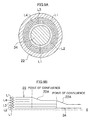
- Figs. 2A and 2B each show an example of a modification of the microreactor 10.
- the flow is contracted by reducing the opening width of the reaction channel 56 near a point of contraction of a plurality of fluids.
- taper portions 43A, 44A having an inclination substantially parallel to the inclination of the taper portion 22A of the round tube portion 22 are formed. As a result of this, it is possible to perform smooth contraction.
- Wb the total of the opening widths W1, W2, W3 of the fluid supply routes 50, 52, 54 before contraction
- Wa the opening width of the reaction channel 56 after contraction
- the opening width of one fluid supply route when contraction is performed as in the example of modification of the present invention, it is possible to make the opening width of one fluid supply route large, for example, to make it larger than the opening width Wa of the reaction channel 56.
- the fluid supply routes 50, 52, 54 are formed as a multicylindrical structure, it is preferred that the fluid supply ports of the plurality of fluid supply tubes 38, 40, 42 be arranged at equal intervals in the circumferential direction of the multicylindrical structure in order to supply fluid uniformly to the fluid supply routes 50, 52, 54.
- Fig. 2B shows an example of modification in which the fluid supply tubes 38, 40, 42 are each provided with 4 fluid supply ports spaced at 90° intervals. Arranging a plurality of fluid supply ports in this manner applies also to the microreactor 10 of Figs. 1A and 1B for which contraction is not performed.
- the inclination angle ⁇ of the taper portion 22A when contraction is performed is not less than 1° but less than 90° with respect to the axis S, preferably not less than 1 ° but less than 60°, and especially preferably not less than 1 ° but less than 30°.
- the taper portion 22A be formed in streamlined shape by rounding the start position (contraction start position) and end position (contraction end position) of the taper portion 22A. Because by forming the taper portion 22A in streamlined shape in this manner, the fluid is smoothly contracted, it can be further ensured that the exfoliation of the flow from the wall surface, eddy currents, stagnation, etc. do not occur.
- the construction of the microreactor 10 used in a reaction method of the present invention is such that the microreactor provides a plurality of supply routes 50, 52, 54 in communication with one reaction channel 56 as a multicylindrical structure having a co-axis and causes a plurality of fluids L1, L2, L3 to flow together in the reaction channel 56 via the respective fluid supply routes 50, 52, 54, whereby these fluids are coaxially laminated and caused to flow as laminar flows whose sections orthogonal to the co-axis are annular and the fluids are diffused in a normal direction of contact interfaces thereof to cause a reaction. And in a reaction method of the present invention, at lest one of the plurality of laminated fluids L1, L2, L3 is constituted by a fluid not participating in the reaction of other fluids.
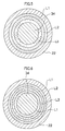
- Fig. 3 to Figs. 9A to 9B show various modes of a reaction method of the present invention, each being a sectional view in the radial direction of the reaction channel 56 (direction orthogonal to the flow of the fluids).
- Fig. 3 shows a case where two kinds of fluid L1, L2 are supplied to two fluid supply routes, one fluid participating in the reaction and the other not participating in the reaction, whereby the fluids are laminated in the shape of a two-layer circular ring and caused to flow through the reaction channel 56.
- the number of the fluids participating in the reaction is one.
- This is a reaction method by which the reaction is caused by adding energy (light, heat, etc.) from the outside to one fluid which previously contains a substance promoting the reaction such as a catalyst.
- energy light, heat, etc.
- it is possible to cause heat to be received from or given to the fluid not participating in the reaction as a heating medium and it is also possible to use the fluid not participating in the reaction in controlling the reaction temperature.
- Fig. 4 shows a case where by supplying four kinds of fluids L1, L2, L3, L4, which include fluids (or a fluid) participating in the reaction and fluids (or a fluid) not participating in the reaction, to four fluid supply routes, whereby these fluids are laminated in the shape of a four-layer circular ring and caused to flow through the reaction channel 56.
- Fig. 5 shows a case where by supplying three kinds of fluids L1, L2, L3, which include fluids participating in the reaction and a fluid not participating in the reaction, to three fluid supply routes, whereby these fluids are laminated in the shape of a three-layer circular ring and caused to flow through the reaction channel 56.
- a laminar flow of the fluid L2 not participating in the reaction is sandwiched between laminar flows formed by the fluids L1, L3 participating in the reaction.
- the fluids L1, L3 participating in the reaction By constituting the laminations of the fluids L1, L3 participating in the reaction and the fluid 2 not participating in the reaction in this manner, it is ensured that with the fluid L2 not participating in the reaction serving as a substantial reaction-carrying-out layer, the fluids L1, L3 participating in the reaction, which sandwich this reaction-carrying-out layer, can be used as a pair of solute supply layers to supply solutes for performing the reaction. That is, it is ensured that solutes which are diffused from the pair of solute supply layers on both sides to the reaction-carrying-out layer can be caused to react in a condition appropriately diluted in the reaction-carrying-out layer. As a result of this, it is possible to prevent coagulation which might occur when solutes are caused to react with each other under high concentration conditions or to improve the homogenization of reaction products formed by the reaction.
- Fig. 6 shows a case where by supplying three kinds of fluids L1, L2, L3, which include fluids participating in the reaction and fluids not participating in the reaction, to four fluid supply routes, whereby these fluids are laminated in the shape of a four-layer circular ring and caused to flow through the reaction channel 56.
- one fluid L1 not participating in the reaction is caused to flow on the side of the outer peripheral wall of the reaction channel 56 and another fluid L1 not participating in the reaction is caused to flow on the side of the inner peripheral wall of the reaction channel 56.
- the plurality of fluid supply routes 50, 52, 54 are formed as a multicylindrical structure having a co-axis so that laminar flows in the shape of a circular ring are formed in the reaction channel 56 and the number of wall surfaces of the reaction channel 56 is only two, i.e., the wall surfaces of the reaction channel 56 are only the inner circumferential wall surface and the outer circumferential wall surface.
- Figs. 7A and 7B each show a case where by supplying three kinds of fluids L1, L2, L3, which include fluids participating in the reaction and a fluid not participating in the reaction, to three fluid supply routes, whereby these fluids are laminated in the shape of a three-layer circular ring and caused to flow through the reaction channel 56.
- the flow rate of the fluid L1 not participating in the reaction is increased or decreased.
- the substance diffusion which involves the diffusion of fluids in a normal direction of contact surfaces of the fluids is basic to the reaction, the opening width of the reaction channel 56, which is a microspace, i.e., the distance orthogonal to the flow of fluids determines the characteristics of the reaction. Therefore, in a case where conventionally, fluids having different reaction characteristics are caused to react by use of the same microreactor, it was impossible to cause an optimum reaction and it was feared that uniform reaction products may be formed.
- Fig. 8 shows a case where among six fluid supply routes, only the innermost and outermost fluid supply routes are supplied with the fluid L1 not participating in the reaction so that the fluids L2, L3 participating in the reaction are alternately arranged in the four fluid supply routes between the innermost and outermost fluid supply routes, whereby regular annular laminar flows are formed.
- the reaction occurs due to the diffusion from both inner and outer sides by arranging the fluids L2, L3 participating in the reaction as annual-rings-like layers having regularity, it is possible not only to accelerate the reaction, but also reduce the thickness of the fluid per layer even when the supply volume of the fluids participating in the reaction is the same, and this reduction of the thickness also promotes the reaction. Furthermore, by arranging the fluid L1 not participating in the reaction in the innermost and outermost fluid supply routes, it is ensured that coagulated matter and precipitates formed by the reaction do not adhere to the wall surface of the reaction channel 56 or be deposited on this wall surface.
- Fig. 9A and Fig. 9B show a case where among five fluid supply routes, in order from the innermost fluid supply routes, the fluid L1 not participating in the reaction, the extraction fluid L2, the fluid L3 participating in the reaction, the fluid L4 participating in the reaction, and the fluid L1 not participating in the reaction are supplied. Because in this manner, apart from the layers of the fluids L3,14 participating in the reaction, the layer of the extraction fluid L2 for the extraction and separation of reaction products is formed, it is possible to efficiently extract and separate reaction products into the layer of the extraction fluid L2. In this case, it is desirable to combine a multistage reaction and multistage contraction. That is, as shown in Fig.
- the reaction is caused to occur by causing the fluids L3, L4 participating in the reaction to flow together, and when reaction products have been formed to a certain degree, the reaction products are extracted and separated by causing the extraction fluid L2 to flow together with the fluids L3, L4.
- the reaction products can be efficiently separated by separating and taking out only the layer of the extraction fluid L2 after the extraction and separation of the reaction products.
- a reaction which involves the generation of fine particles silver chloride (AgCl) was caused to occur.
- the innermost fluid supply route which comes into contact with the inner peripheral wall surface and outer peripheral wall surface of the reaction channel 56 and the outermost fluid supply route were each supplied with distilled water as a fluid not participating in the reaction
- the second fluid supply route from the inside was supplied with a silver nitrate fluid (AgNO 3 )
- the third fluid supply route from the inside was supplied with a sodium chloride fluid (NaCl).
- the opening width of the reaction channel 56 was 225 ⁇ m.
- each fluid was caused to contain 0.06 wt % low molecular weight gelatin with a molecular weight of about 20,000 as a protective colloid during the formation of fine particles.
- the fluid temperature was 296 ⁇ 1 K as absolute temperature (23 ⁇ 1°C) as centigrade temperature.
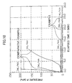
- a pressure gauge was installed in the piping between a fluid supply route of the microreactor and a pump which feeds liquids to the fluid supply route, and changes in pressure were investigated. The result of the investigation is shown in Fig. 10.
- the reaction involves the formation of fine particles of silver chloride (AgCl)
- the fine particles are apt to adhere to the wall surface of the reaction channel and be deposited on the wall surface, with the result that the reaction channel will be clogged in a short time.
- the pressure measured for 15 minutes after the start of operation was constant at 10 (kPa) when the flow rate Q was 3.0 (ml/minute)
- the pressure measured for 22 minutes after the start of operation was constant at 7 (kPa) when the flow rate Q was 2.0 (ml/minute)
- the pressure measured for 30 minutes after the start of operation scarcely showed any rise when the flow rate Q was 1.0 (ml/minute).
- the effect of the forming of the fluid supply routes as a multicylindrical structure having a co-axis on the prevention of clogging was also ascertained. It might be thought that this is because the forming of the fluid supply routes in a cylindrical shape eliminates the presence of corner portions which are due to rectangular fluid supply routes as in a conventional microreactor, with the result that the adhering of fine particles in corner portions does not occur. Therefore, the best multicylindrical structure of a fluid supply route is a structure of multiple circular cylinders, and in the case of a structure of multiple polyangular cylinders, the closer to a circular shape, the more desirable.
- Example 2 Example of a reaction using fluorine gas
- a fluorination reaction was caused to occur by use of a stainless steel microreactor as shown in Fig. 6, which is provided with four fluid supply routes formed as a multicylindrical structure having a co-axis (opening width of the reaction channel 56: 225 ⁇ m).
- a cooling medium at -20°C was circulated as the heat medium C1 shown in Figs. 2A and 2B in order to control the reaction temperature, and perfluorohexane which is a solvent not participating in the reaction was caused to flow as the fluid L1 of Fig. 6.
- 10 vol. % fluorine gas in nitrogen was caused to flow (10 ml/minute) as the fluid L2
- ethyl acetoacetate diluted with F-113 (1,1,2-richloro-trifluoroethane) concentration: 10 wt. %) was caused to flow as the fluid L3 at a flow rate of 5 ml/h.
- a reaction to synthesize an organic pigment of the following reaction formula was caused to occur by use of a stainless steel microreactor as shown in Fig. 8, which is provided with six fluid supply routes formed as a multicylindrical structure having a co-axis (opening width of the reaction channel 56: 300 ⁇ m).
- Silicon oil heated to 180°C was circulated as the heat medium C1 shown in Figs. 1A and 1B in order to control the reaction temperature, and 1,2-dichlorobenzene which is a solvent at 80°C was caused to flow as the fluid L1 of Fig. 8.
- a solution obtained by causing 37.9 g (0.1 mol) of the above compound (A) to be suspended in 300 ml of 1,2-dichlorobenzene at 80°C was dissolved in 300 ml of 1,2-dichlorobenzene and heated to 80°C, and this solution was caused to flow each time at a flow rate of 6 ml/minute by use of a piston pump.
- a reaction to synthesize an organic silver salt was caused to occur by use of a stainless steel microreactor as shown in Fig. 6, which is provided with four fluid supply routes formed as a multicylindrical structure having a co-axis (opening width of the reaction channel 56: 300 ⁇ m).
- an aqueous solution of fatty acid sodium containing behenic acid as a main component held at 75°C prepared by mixing 2.6 moles of fatty acid with 4.21 of distilled water, 500 ml of an aqueous solution of NaOH with a concentration of 5 mol/l and 1.21 of t-butanol and stirring the mixture at 75°C for 1 hour
- an aqueous solution of silver nitrate held at 75°C as the fluid L3 an aqueous solution obtained by dissolving 400 g of silver nitrite in stilled water so that the volume becomes 2.11, pH 4.0
Landscapes
- Chemical & Material Sciences (AREA)
- Chemical Kinetics & Catalysis (AREA)
- Organic Chemistry (AREA)
- Physical Or Chemical Processes And Apparatus (AREA)
- Extraction Or Liquid Replacement (AREA)
- Organic Low-Molecular-Weight Compounds And Preparation Thereof (AREA)
Applications Claiming Priority (4)
| Application Number | Priority Date | Filing Date | Title |
|---|---|---|---|
| JP2003154404 | 2003-05-30 | ||
| JP2003154404 | 2003-05-30 | ||
| JP2003189657A JP4407177B2 (ja) | 2003-05-30 | 2003-07-01 | マイクロリアクターを用いた反応方法 |
| JP2003189657 | 2003-07-01 |
Publications (1)
| Publication Number | Publication Date |
|---|---|
| EP1481724A1 true EP1481724A1 (fr) | 2004-12-01 |
Family
ID=33134381
Family Applications (1)
| Application Number | Title | Priority Date | Filing Date |
|---|---|---|---|
| EP20040012710 Withdrawn EP1481724A1 (fr) | 2003-05-30 | 2004-05-28 | Procédé de réaction en utilisant un microréacteur |
Country Status (4)
| Country | Link |
|---|---|
| US (1) | US7579191B2 (fr) |
| EP (1) | EP1481724A1 (fr) |
| JP (1) | JP4407177B2 (fr) |
| CN (1) | CN100408157C (fr) |
Cited By (14)
| Publication number | Priority date | Publication date | Assignee | Title |
|---|---|---|---|---|
| JP2005046651A (ja) * | 2003-05-30 | 2005-02-24 | Fuji Photo Film Co Ltd | マイクロリアクターを用いた反応方法 |
| EP1880756A1 (fr) * | 2006-07-18 | 2008-01-23 | Fuji Xerox Co., Ltd. | Dispositif à micro-canaux |
| WO2008043860A1 (fr) * | 2006-10-13 | 2008-04-17 | Rhodia Operations | Procede de preparation d'un polymere |
| WO2008061058A2 (fr) * | 2006-11-10 | 2008-05-22 | Luminex Corporation | Ensemble cytomètre de flux et conduit fluidique comportant des aiguilles d'injection multiples |
| WO2011110742A1 (fr) * | 2010-03-10 | 2011-09-15 | Wetend Technologies Oy | Procédé et appareil pour le mélange de différents flux dans un flux de liquide de traitement |
| WO2011110745A3 (fr) * | 2010-03-10 | 2011-10-27 | Wetend Technologies Oy | Procédé et réacteur pour le mélange d'un ou plusieurs produits chimiques dans un écoulement de liquide de traitement |
| WO2012025548A1 (fr) | 2010-08-27 | 2012-03-01 | Solvay Sa | Procédé pour la préparation d'alcénones |
| US8349273B2 (en) | 2007-10-12 | 2013-01-08 | Fuji Xerox Co., Ltd. | Microreactor device |
| US20130062030A1 (en) * | 2010-03-10 | 2013-03-14 | Wetend Technologies Oy | Method and a reactor for in-line production of calcium carbonate into the production process of a fibrous web |
| US8585278B2 (en) | 2009-03-16 | 2013-11-19 | Fuji Xerox Co., Ltd. | Micro fluidic device and fluid control method |
| EP2664607A1 (fr) | 2012-05-16 | 2013-11-20 | Solvay Sa | Processus de fluoration |
| US8679336B2 (en) | 2008-11-14 | 2014-03-25 | Fuji Xerox Co., Ltd. | Microchannel device, separation apparatus, and separation method |
| US8721992B2 (en) | 2007-03-27 | 2014-05-13 | Fuji Xerox Co., Ltd | Micro fluidic device |
| EP2883601A1 (fr) * | 2013-12-16 | 2015-06-17 | China Petrochemical Development Corporation, Taipei (Taiwan) | Dispositif de mélange de fluides |
Families Citing this family (34)
| Publication number | Priority date | Publication date | Assignee | Title |
|---|---|---|---|---|
| JP4431857B2 (ja) * | 2003-05-30 | 2010-03-17 | 富士フイルム株式会社 | マイクロデバイス |
| JP4587757B2 (ja) * | 2003-09-22 | 2010-11-24 | 富士フイルム株式会社 | 有機顔料微粒子およびその製造方法 |
| FI115148B (fi) * | 2003-10-08 | 2005-03-15 | Wetend Technologies Oy | Menetelmä ja laite kemikaalin syöttämiseksi nestevirtaan |
| JP2007098226A (ja) * | 2005-09-30 | 2007-04-19 | Fujifilm Corp | 流体デバイス |
| JP5345750B2 (ja) * | 2005-09-30 | 2013-11-20 | 富士フイルム株式会社 | 流体デバイス |
| CA2625288A1 (fr) * | 2005-10-10 | 2007-04-19 | Brandenburgische Technische Universitaet Cottbus | Reacteur a couche de separation avec ecoulement elongationnel |
| JP4837410B2 (ja) | 2006-03-22 | 2011-12-14 | 富士フイルム株式会社 | 標的化合物の検出方法 |
| JP4901260B2 (ja) * | 2006-03-28 | 2012-03-21 | 富士フイルム株式会社 | 流体混合装置及び流体混合方法 |
| JP4592644B2 (ja) * | 2006-06-02 | 2010-12-01 | 東レエンジニアリング株式会社 | マイクロリアクタ |
| JP5064756B2 (ja) * | 2006-10-11 | 2012-10-31 | キヤノン株式会社 | 混合装置および色材分散物の製造装置 |
| JP2008169335A (ja) | 2007-01-12 | 2008-07-24 | Fujifilm Corp | 有機顔料微粒子分散液の製造方法、それにより得られる有機顔料微粒子およびその分散液 |
| JP4226634B2 (ja) * | 2007-03-29 | 2009-02-18 | 財団法人 岡山県産業振興財団 | マイクロリアクター |
| KR101358261B1 (ko) * | 2007-07-06 | 2014-02-05 | 엠. 테크닉 가부시키가이샤 | 세라믹스 나노입자의 제조 방법 |
| JP4691698B2 (ja) * | 2007-07-06 | 2011-06-01 | エム・テクニック株式会社 | 顔料ナノ粒子の製造方法、及び、インクジェット用インクの製造方法 |
| JP5052990B2 (ja) * | 2007-08-10 | 2012-10-17 | 富士フイルム株式会社 | 多段混合マイクロデバイス |
| JP5540525B2 (ja) * | 2008-03-03 | 2014-07-02 | 富士ゼロックス株式会社 | 凝集樹脂粒子の製造方法 |
| JP5336111B2 (ja) * | 2008-06-09 | 2013-11-06 | 富士フイルム株式会社 | 有機顔料微粒子分散物の製造方法、これにより得られる有機顔料微粒子を用いたインクジェット記録用インク及び塗料 |
| JP5604038B2 (ja) * | 2008-08-25 | 2014-10-08 | 株式会社日立製作所 | 反応装置及び反応プラント |
| JP5081845B2 (ja) | 2009-02-10 | 2012-11-28 | 株式会社日立製作所 | 粒子製造装置 |
| JP2010247071A (ja) * | 2009-04-16 | 2010-11-04 | Hitachi Plant Technologies Ltd | 流体混合器 |
| JP5116114B2 (ja) * | 2009-07-27 | 2013-01-09 | 富士フイルム株式会社 | マイクロ化学装置の運転方法 |
| JP2011147932A (ja) * | 2009-12-24 | 2011-08-04 | Kao Corp | 流体混合器 |
| JP5706611B2 (ja) * | 2009-12-28 | 2015-04-22 | 株式会社日立製作所 | アクロレインの合成方法 |
| JP2011219381A (ja) * | 2010-04-06 | 2011-11-04 | Dai Ichi Kogyo Seiyaku Co Ltd | N−オキシル化合物の製法 |
| WO2011125437A1 (fr) * | 2010-04-06 | 2011-10-13 | 第一工業製薬株式会社 | Procédé de fabrication d'un composé de n-oxyle |
| CA2705055C (fr) * | 2010-05-20 | 2015-11-03 | Suncor Energy Inc. | Procede et dispositif d'injection en ligne d'un floculant dans un flux de liquides de residus fins murs |
| JP5109004B1 (ja) * | 2011-11-11 | 2012-12-26 | マイクロ波化学株式会社 | 化学反応装置 |
| EP3303272B1 (fr) * | 2015-06-04 | 2020-07-08 | Solvay Specialty Polymers Italy S.p.A. | Procédés pour la synthèse de 1,2,3,4-tétrachloro-hexafluoro-butane |
| JP6968578B2 (ja) * | 2017-05-29 | 2021-11-17 | 一般財団法人電力中央研究所 | マイクロリアクター、並びに、抽出方法及び反応方法 |
| US11891302B2 (en) | 2020-03-17 | 2024-02-06 | Bayotech, Inc. | Hydrogen generation systems |
| US10894244B1 (en) | 2020-03-17 | 2021-01-19 | Bayotech, Inc. | Hydrogen generation systems |
| US11597649B2 (en) | 2020-03-17 | 2023-03-07 | Bayotech, Inc. | Steam methane reformer hydrogen generation systems |
| EP4059491A1 (fr) * | 2021-03-17 | 2022-09-21 | Evonik Operations GmbH | Dispositif et procédé de production de nanoporteuses et/ou de nanoformulations |
| CN115463566B (zh) * | 2022-09-29 | 2023-09-26 | 上海蕙黔新材料科技有限公司 | 一种用于气相法羰基合成碳酸二甲酯的氧气混合器 |
Citations (6)
| Publication number | Priority date | Publication date | Assignee | Title |
|---|---|---|---|---|
| DE19541266A1 (de) | 1995-11-06 | 1997-05-07 | Bayer Ag | Verfahren und Vorrichtung zur Durchführung chemischer Reaktionen mittels eines Mikrostruktur-Lamellenmischers |
| WO2000062913A1 (fr) | 1999-04-16 | 2000-10-26 | INSTITUT FüR MIKROTECHNIK MAINZ GMBH | Procede et micromelangeur pour la realisation d'une dispersion |
| US6225497B1 (en) | 1998-01-09 | 2001-05-01 | Bayer Aktiengesellschaft | Process for the phosgenation of amines in the gas phase using microstructure mixers |
| JP2003502144A (ja) | 1999-06-19 | 2003-01-21 | フォルシュングスツェントルム カールスルーエ ゲゼルシャフト ミット ベシュレンクテル ハフツング | 静力学的マイクロミキサー |
| DE10148615A1 (de) | 2001-09-26 | 2003-04-24 | Inst Mikrotechnik Mainz Gmbh | Verfahren und Vorrichtung zur Durchführung chemischer Prozesse |
| EP1329765A2 (fr) * | 2002-01-18 | 2003-07-23 | Fuji Photo Film Co., Ltd. | Procédé et dispositif pour la préparation d'émulsions photographiques à l'halogénure d'argent |
Family Cites Families (10)
| Publication number | Priority date | Publication date | Assignee | Title |
|---|---|---|---|---|
| JPH03211284A (ja) * | 1990-01-17 | 1991-09-17 | Nippon Koshuha Kk | 多段熱プラズマ反応装置 |
| JPH06186656A (ja) | 1992-12-17 | 1994-07-08 | Konica Corp | ハロゲン化銀粒子の製造方法及び製造装置 |
| JPH06226085A (ja) * | 1993-02-03 | 1994-08-16 | Asahi Glass Co Ltd | 酸化物微粒子の製造装置および製造方法 |
| DE69628016T2 (de) * | 1995-06-16 | 2004-04-01 | University Of Washington, Seattle | Miniaturisierte differentielle extraktionsvorrichtung und verfahren |
| US20010050881A1 (en) * | 1999-09-20 | 2001-12-13 | Depaoli David W. | Continuous flow, electrohydrodynamic micromixing apparatus and methods |
| JP2002001102A (ja) * | 2000-06-20 | 2002-01-08 | Kanagawa Acad Of Sci & Technol | マイクロチャンネル構造 |
| JP3538777B2 (ja) | 2001-03-26 | 2004-06-14 | 独立行政法人産業技術総合研究所 | 微小化学反応装置 |
| JP4385541B2 (ja) * | 2001-04-02 | 2009-12-16 | 三菱化学株式会社 | 流通型微小反応流路,反応装置及び反応方法 |
| JP4792664B2 (ja) * | 2001-06-15 | 2011-10-12 | コニカミノルタホールディングス株式会社 | 混合方法、混合機構、該混合機構を備えたマイクロミキサーおよびマイクロチップ |
| JP4407177B2 (ja) * | 2003-05-30 | 2010-02-03 | 富士フイルム株式会社 | マイクロリアクターを用いた反応方法 |
-
2003
- 2003-07-01 JP JP2003189657A patent/JP4407177B2/ja not_active Expired - Fee Related
-
2004
- 2004-05-27 US US10/854,805 patent/US7579191B2/en not_active Expired - Fee Related
- 2004-05-28 CN CNB2004100464144A patent/CN100408157C/zh not_active Expired - Fee Related
- 2004-05-28 EP EP20040012710 patent/EP1481724A1/fr not_active Withdrawn
Patent Citations (6)
| Publication number | Priority date | Publication date | Assignee | Title |
|---|---|---|---|---|
| DE19541266A1 (de) | 1995-11-06 | 1997-05-07 | Bayer Ag | Verfahren und Vorrichtung zur Durchführung chemischer Reaktionen mittels eines Mikrostruktur-Lamellenmischers |
| US6225497B1 (en) | 1998-01-09 | 2001-05-01 | Bayer Aktiengesellschaft | Process for the phosgenation of amines in the gas phase using microstructure mixers |
| WO2000062913A1 (fr) | 1999-04-16 | 2000-10-26 | INSTITUT FüR MIKROTECHNIK MAINZ GMBH | Procede et micromelangeur pour la realisation d'une dispersion |
| JP2003502144A (ja) | 1999-06-19 | 2003-01-21 | フォルシュングスツェントルム カールスルーエ ゲゼルシャフト ミット ベシュレンクテル ハフツング | 静力学的マイクロミキサー |
| DE10148615A1 (de) | 2001-09-26 | 2003-04-24 | Inst Mikrotechnik Mainz Gmbh | Verfahren und Vorrichtung zur Durchführung chemischer Prozesse |
| EP1329765A2 (fr) * | 2002-01-18 | 2003-07-23 | Fuji Photo Film Co., Ltd. | Procédé et dispositif pour la préparation d'émulsions photographiques à l'halogénure d'argent |
Cited By (21)
| Publication number | Priority date | Publication date | Assignee | Title |
|---|---|---|---|---|
| JP2005046651A (ja) * | 2003-05-30 | 2005-02-24 | Fuji Photo Film Co Ltd | マイクロリアクターを用いた反応方法 |
| EP1880756A1 (fr) * | 2006-07-18 | 2008-01-23 | Fuji Xerox Co., Ltd. | Dispositif à micro-canaux |
| US8418719B2 (en) | 2006-07-18 | 2013-04-16 | Fuji Xerox Co., Ltd. | Microchannel device |
| WO2008043860A1 (fr) * | 2006-10-13 | 2008-04-17 | Rhodia Operations | Procede de preparation d'un polymere |
| WO2008043922A3 (fr) * | 2006-10-13 | 2008-06-19 | Rhodia Operations | Procede et installation de determination d'au moins un parametre d'une transformation physique et/ou chimique, et procede de criblage correspondant |
| WO2008061058A2 (fr) * | 2006-11-10 | 2008-05-22 | Luminex Corporation | Ensemble cytomètre de flux et conduit fluidique comportant des aiguilles d'injection multiples |
| WO2008061058A3 (fr) * | 2006-11-10 | 2008-07-03 | Luminex Corp | Ensemble cytomètre de flux et conduit fluidique comportant des aiguilles d'injection multiples |
| US8062609B2 (en) | 2006-11-10 | 2011-11-22 | Luminex Corporation | Flow cytometer and fluidic line assembly with multiple injection needles |
| US8394326B2 (en) | 2006-11-10 | 2013-03-12 | Luminex Corporation | Flow cytometer and fluidic line assembly with multiple injection needles |
| US8721992B2 (en) | 2007-03-27 | 2014-05-13 | Fuji Xerox Co., Ltd | Micro fluidic device |
| US8349273B2 (en) | 2007-10-12 | 2013-01-08 | Fuji Xerox Co., Ltd. | Microreactor device |
| US8679336B2 (en) | 2008-11-14 | 2014-03-25 | Fuji Xerox Co., Ltd. | Microchannel device, separation apparatus, and separation method |
| US8585278B2 (en) | 2009-03-16 | 2013-11-19 | Fuji Xerox Co., Ltd. | Micro fluidic device and fluid control method |
| US20130062030A1 (en) * | 2010-03-10 | 2013-03-14 | Wetend Technologies Oy | Method and a reactor for in-line production of calcium carbonate into the production process of a fibrous web |
| WO2011110745A3 (fr) * | 2010-03-10 | 2011-10-27 | Wetend Technologies Oy | Procédé et réacteur pour le mélange d'un ou plusieurs produits chimiques dans un écoulement de liquide de traitement |
| WO2011110742A1 (fr) * | 2010-03-10 | 2011-09-15 | Wetend Technologies Oy | Procédé et appareil pour le mélange de différents flux dans un flux de liquide de traitement |
| US8852402B2 (en) * | 2010-03-10 | 2014-10-07 | Wetend Technologies Oy | Method for producing calcium carbonate during formation of a fibrous web |
| US9339774B2 (en) | 2010-03-10 | 2016-05-17 | Wetend Technologies Oy | Method and apparatus for mixing various flows into a process liquid flow |
| WO2012025548A1 (fr) | 2010-08-27 | 2012-03-01 | Solvay Sa | Procédé pour la préparation d'alcénones |
| EP2664607A1 (fr) | 2012-05-16 | 2013-11-20 | Solvay Sa | Processus de fluoration |
| EP2883601A1 (fr) * | 2013-12-16 | 2015-06-17 | China Petrochemical Development Corporation, Taipei (Taiwan) | Dispositif de mélange de fluides |
Also Published As
| Publication number | Publication date |
|---|---|
| JP4407177B2 (ja) | 2010-02-03 |
| US7579191B2 (en) | 2009-08-25 |
| JP2005046651A (ja) | 2005-02-24 |
| CN100408157C (zh) | 2008-08-06 |
| CN1572363A (zh) | 2005-02-02 |
| US20050036921A1 (en) | 2005-02-17 |
Similar Documents
| Publication | Publication Date | Title |
|---|---|---|
| US7579191B2 (en) | Reaction method using microreactor | |
| US7434982B2 (en) | Micro mixing and reaction device | |
| JP4432104B2 (ja) | マイクロリアクター | |
| US8551417B2 (en) | Reactor and reaction plant | |
| JP2020114585A (ja) | プロセス強化マイクロ流体装置 | |
| US8524173B2 (en) | Microchannel structure and fine-particle production method using the same | |
| JP4339163B2 (ja) | マイクロデバイスおよび流体の合流方法 | |
| US20120077992A1 (en) | Device for carrying out chemical reactions under homogenous and heterogenous conditions | |
| EP2431091A1 (fr) | Réacteur de type à écoulement tubulaire | |
| JP2005512760A (ja) | 少なくとも2つの流体を混合及び反応させるための装置 | |
| JP2011504221A (ja) | マイクロ流体の自励発振ミキサおよび装置ならびにその使用方法 | |
| JP4792268B2 (ja) | 流体デバイス | |
| US11826311B2 (en) | Coaxial nozzle configuration and methods thereof | |
| US20090253841A1 (en) | Method for producing chemicals | |
| US20070074773A1 (en) | Fluidic device | |
| EP1762298A1 (fr) | Microreacteur à deux solutions ayant cannelures en forme de secteur | |
| JP6968578B2 (ja) | マイクロリアクター、並びに、抽出方法及び反応方法 | |
| JP3745281B2 (ja) | マイクロミキサー | |
| JP2007268488A (ja) | マイクロ科学装置の流体操作方法、及びマイクロ科学装置 | |
| JP4724619B2 (ja) | 流体処理装置及び流体処理方法 | |
| JP2005224764A (ja) | マイクロリアクターを用いた反応方法及びマイクロリアクター | |
| US11014063B2 (en) | Device for processing and conditioning of material transported through the device | |
| JP2007268492A (ja) | マイクロデバイス及びその運転方法 | |
| JPH10202089A (ja) | 微分割された、ホモ分散懸濁液の製造 | |
| JPH11188079A (ja) | 継目なしカプセル粒子の製造方法 |
Legal Events
| Date | Code | Title | Description |
|---|---|---|---|
| PUAI | Public reference made under article 153(3) epc to a published international application that has entered the european phase |
Free format text: ORIGINAL CODE: 0009012 |
|
| AK | Designated contracting states |
Kind code of ref document: A1 Designated state(s): AT BE BG CH CY CZ DE DK EE ES FI FR GB GR HU IE IT LI LU MC NL PL PT RO SE SI SK TR |
|
| AX | Request for extension of the european patent |
Extension state: AL HR LT LV MK |
|
| 17P | Request for examination filed |
Effective date: 20050217 |
|
| AKX | Designation fees paid |
Designated state(s): AT BE BG CH CY CZ DE DK EE ES FI FR GB GR HU IE IT LI LU MC NL PL PT RO SE SI SK TR |
|
| RAP1 | Party data changed (applicant data changed or rights of an application transferred) |
Owner name: FUJIFILM CORPORATION |
|
| 17Q | First examination report despatched |
Effective date: 20091201 |
|
| STAA | Information on the status of an ep patent application or granted ep patent |
Free format text: STATUS: THE APPLICATION IS DEEMED TO BE WITHDRAWN |
|
| 18D | Application deemed to be withdrawn |
Effective date: 20161201 |