EP1479900B1 - Exhaust gas purification system for internal combustion engine - Google Patents
Exhaust gas purification system for internal combustion engine Download PDFInfo
- Publication number
- EP1479900B1 EP1479900B1 EP04011572A EP04011572A EP1479900B1 EP 1479900 B1 EP1479900 B1 EP 1479900B1 EP 04011572 A EP04011572 A EP 04011572A EP 04011572 A EP04011572 A EP 04011572A EP 1479900 B1 EP1479900 B1 EP 1479900B1
- Authority
- EP
- European Patent Office
- Prior art keywords
- exhaust gas
- sox
- gas purification
- amount
- collection
- Prior art date
- Legal status (The legal status is an assumption and is not a legal conclusion. Google has not performed a legal analysis and makes no representation as to the accuracy of the status listed.)
- Expired - Fee Related
Links
Images


Classifications
-
- F—MECHANICAL ENGINEERING; LIGHTING; HEATING; WEAPONS; BLASTING
- F01—MACHINES OR ENGINES IN GENERAL; ENGINE PLANTS IN GENERAL; STEAM ENGINES
- F01N—GAS-FLOW SILENCERS OR EXHAUST APPARATUS FOR MACHINES OR ENGINES IN GENERAL; GAS-FLOW SILENCERS OR EXHAUST APPARATUS FOR INTERNAL COMBUSTION ENGINES
- F01N3/00—Exhaust or silencing apparatus having means for purifying, rendering innocuous, or otherwise treating exhaust
- F01N3/08—Exhaust or silencing apparatus having means for purifying, rendering innocuous, or otherwise treating exhaust for rendering innocuous
- F01N3/0807—Exhaust or silencing apparatus having means for purifying, rendering innocuous, or otherwise treating exhaust for rendering innocuous by using absorbents or adsorbents
- F01N3/0828—Exhaust or silencing apparatus having means for purifying, rendering innocuous, or otherwise treating exhaust for rendering innocuous by using absorbents or adsorbents characterised by the absorbed or adsorbed substances
- F01N3/085—Sulfur or sulfur oxides
-
- B—PERFORMING OPERATIONS; TRANSPORTING
- B01—PHYSICAL OR CHEMICAL PROCESSES OR APPARATUS IN GENERAL
- B01D—SEPARATION
- B01D53/00—Separation of gases or vapours; Recovering vapours of volatile solvents from gases; Chemical or biological purification of waste gases, e.g. engine exhaust gases, smoke, fumes, flue gases, aerosols
- B01D53/34—Chemical or biological purification of waste gases
- B01D53/92—Chemical or biological purification of waste gases of engine exhaust gases
- B01D53/94—Chemical or biological purification of waste gases of engine exhaust gases by catalytic processes
- B01D53/9404—Removing only nitrogen compounds
- B01D53/9409—Nitrogen oxides
- B01D53/9431—Processes characterised by a specific device
-
- B—PERFORMING OPERATIONS; TRANSPORTING
- B01—PHYSICAL OR CHEMICAL PROCESSES OR APPARATUS IN GENERAL
- B01D—SEPARATION
- B01D53/00—Separation of gases or vapours; Recovering vapours of volatile solvents from gases; Chemical or biological purification of waste gases, e.g. engine exhaust gases, smoke, fumes, flue gases, aerosols
- B01D53/34—Chemical or biological purification of waste gases
- B01D53/92—Chemical or biological purification of waste gases of engine exhaust gases
- B01D53/94—Chemical or biological purification of waste gases of engine exhaust gases by catalytic processes
- B01D53/9495—Controlling the catalytic process
-
- F—MECHANICAL ENGINEERING; LIGHTING; HEATING; WEAPONS; BLASTING
- F01—MACHINES OR ENGINES IN GENERAL; ENGINE PLANTS IN GENERAL; STEAM ENGINES
- F01N—GAS-FLOW SILENCERS OR EXHAUST APPARATUS FOR MACHINES OR ENGINES IN GENERAL; GAS-FLOW SILENCERS OR EXHAUST APPARATUS FOR INTERNAL COMBUSTION ENGINES
- F01N13/00—Exhaust or silencing apparatus characterised by constructional features ; Exhaust or silencing apparatus, or parts thereof, having pertinent characteristics not provided for in, or of interest apart from, groups F01N1/00 - F01N5/00, F01N9/00, F01N11/00
- F01N13/009—Exhaust or silencing apparatus characterised by constructional features ; Exhaust or silencing apparatus, or parts thereof, having pertinent characteristics not provided for in, or of interest apart from, groups F01N1/00 - F01N5/00, F01N9/00, F01N11/00 having two or more separate purifying devices arranged in series
-
- F—MECHANICAL ENGINEERING; LIGHTING; HEATING; WEAPONS; BLASTING
- F01—MACHINES OR ENGINES IN GENERAL; ENGINE PLANTS IN GENERAL; STEAM ENGINES
- F01N—GAS-FLOW SILENCERS OR EXHAUST APPARATUS FOR MACHINES OR ENGINES IN GENERAL; GAS-FLOW SILENCERS OR EXHAUST APPARATUS FOR INTERNAL COMBUSTION ENGINES
- F01N3/00—Exhaust or silencing apparatus having means for purifying, rendering innocuous, or otherwise treating exhaust
- F01N3/02—Exhaust or silencing apparatus having means for purifying, rendering innocuous, or otherwise treating exhaust for cooling, or for removing solid constituents of, exhaust
- F01N3/021—Exhaust or silencing apparatus having means for purifying, rendering innocuous, or otherwise treating exhaust for cooling, or for removing solid constituents of, exhaust by means of filters
- F01N3/023—Exhaust or silencing apparatus having means for purifying, rendering innocuous, or otherwise treating exhaust for cooling, or for removing solid constituents of, exhaust by means of filters using means for regenerating the filters, e.g. by burning trapped particles
- F01N3/025—Exhaust or silencing apparatus having means for purifying, rendering innocuous, or otherwise treating exhaust for cooling, or for removing solid constituents of, exhaust by means of filters using means for regenerating the filters, e.g. by burning trapped particles using fuel burner or by adding fuel to exhaust
- F01N3/0253—Exhaust or silencing apparatus having means for purifying, rendering innocuous, or otherwise treating exhaust for cooling, or for removing solid constituents of, exhaust by means of filters using means for regenerating the filters, e.g. by burning trapped particles using fuel burner or by adding fuel to exhaust adding fuel to exhaust gases
-
- F—MECHANICAL ENGINEERING; LIGHTING; HEATING; WEAPONS; BLASTING
- F01—MACHINES OR ENGINES IN GENERAL; ENGINE PLANTS IN GENERAL; STEAM ENGINES
- F01N—GAS-FLOW SILENCERS OR EXHAUST APPARATUS FOR MACHINES OR ENGINES IN GENERAL; GAS-FLOW SILENCERS OR EXHAUST APPARATUS FOR INTERNAL COMBUSTION ENGINES
- F01N3/00—Exhaust or silencing apparatus having means for purifying, rendering innocuous, or otherwise treating exhaust
- F01N3/08—Exhaust or silencing apparatus having means for purifying, rendering innocuous, or otherwise treating exhaust for rendering innocuous
- F01N3/0807—Exhaust or silencing apparatus having means for purifying, rendering innocuous, or otherwise treating exhaust for rendering innocuous by using absorbents or adsorbents
- F01N3/0828—Exhaust or silencing apparatus having means for purifying, rendering innocuous, or otherwise treating exhaust for rendering innocuous by using absorbents or adsorbents characterised by the absorbed or adsorbed substances
- F01N3/0842—Nitrogen oxides
-
- F—MECHANICAL ENGINEERING; LIGHTING; HEATING; WEAPONS; BLASTING
- F01—MACHINES OR ENGINES IN GENERAL; ENGINE PLANTS IN GENERAL; STEAM ENGINES
- F01N—GAS-FLOW SILENCERS OR EXHAUST APPARATUS FOR MACHINES OR ENGINES IN GENERAL; GAS-FLOW SILENCERS OR EXHAUST APPARATUS FOR INTERNAL COMBUSTION ENGINES
- F01N3/00—Exhaust or silencing apparatus having means for purifying, rendering innocuous, or otherwise treating exhaust
- F01N3/08—Exhaust or silencing apparatus having means for purifying, rendering innocuous, or otherwise treating exhaust for rendering innocuous
- F01N3/0807—Exhaust or silencing apparatus having means for purifying, rendering innocuous, or otherwise treating exhaust for rendering innocuous by using absorbents or adsorbents
- F01N3/0871—Regulation of absorbents or adsorbents, e.g. purging
- F01N3/0885—Regeneration of deteriorated absorbents or adsorbents, e.g. desulfurization of NOx traps
-
- F—MECHANICAL ENGINEERING; LIGHTING; HEATING; WEAPONS; BLASTING
- F01—MACHINES OR ENGINES IN GENERAL; ENGINE PLANTS IN GENERAL; STEAM ENGINES
- F01N—GAS-FLOW SILENCERS OR EXHAUST APPARATUS FOR MACHINES OR ENGINES IN GENERAL; GAS-FLOW SILENCERS OR EXHAUST APPARATUS FOR INTERNAL COMBUSTION ENGINES
- F01N9/00—Electrical control of exhaust gas treating apparatus
- F01N9/002—Electrical control of exhaust gas treating apparatus of filter regeneration, e.g. detection of clogging
-
- F—MECHANICAL ENGINEERING; LIGHTING; HEATING; WEAPONS; BLASTING
- F01—MACHINES OR ENGINES IN GENERAL; ENGINE PLANTS IN GENERAL; STEAM ENGINES
- F01N—GAS-FLOW SILENCERS OR EXHAUST APPARATUS FOR MACHINES OR ENGINES IN GENERAL; GAS-FLOW SILENCERS OR EXHAUST APPARATUS FOR INTERNAL COMBUSTION ENGINES
- F01N9/00—Electrical control of exhaust gas treating apparatus
- F01N9/005—Electrical control of exhaust gas treating apparatus using models instead of sensors to determine operating characteristics of exhaust systems, e.g. calculating catalyst temperature instead of measuring it directly
-
- F—MECHANICAL ENGINEERING; LIGHTING; HEATING; WEAPONS; BLASTING
- F02—COMBUSTION ENGINES; HOT-GAS OR COMBUSTION-PRODUCT ENGINE PLANTS
- F02D—CONTROLLING COMBUSTION ENGINES
- F02D41/00—Electrical control of supply of combustible mixture or its constituents
- F02D41/02—Circuit arrangements for generating control signals
- F02D41/021—Introducing corrections for particular conditions exterior to the engine
- F02D41/0235—Introducing corrections for particular conditions exterior to the engine in relation with the state of the exhaust gas treating apparatus
- F02D41/027—Introducing corrections for particular conditions exterior to the engine in relation with the state of the exhaust gas treating apparatus to purge or regenerate the exhaust gas treating apparatus
- F02D41/0275—Introducing corrections for particular conditions exterior to the engine in relation with the state of the exhaust gas treating apparatus to purge or regenerate the exhaust gas treating apparatus the exhaust gas treating apparatus being a NOx trap or adsorbent
- F02D41/028—Desulfurisation of NOx traps or adsorbent
-
- F—MECHANICAL ENGINEERING; LIGHTING; HEATING; WEAPONS; BLASTING
- F02—COMBUSTION ENGINES; HOT-GAS OR COMBUSTION-PRODUCT ENGINE PLANTS
- F02D—CONTROLLING COMBUSTION ENGINES
- F02D41/00—Electrical control of supply of combustible mixture or its constituents
- F02D41/02—Circuit arrangements for generating control signals
- F02D41/021—Introducing corrections for particular conditions exterior to the engine
- F02D41/0235—Introducing corrections for particular conditions exterior to the engine in relation with the state of the exhaust gas treating apparatus
- F02D41/027—Introducing corrections for particular conditions exterior to the engine in relation with the state of the exhaust gas treating apparatus to purge or regenerate the exhaust gas treating apparatus
- F02D41/029—Introducing corrections for particular conditions exterior to the engine in relation with the state of the exhaust gas treating apparatus to purge or regenerate the exhaust gas treating apparatus the exhaust gas treating apparatus being a particulate filter
-
- F—MECHANICAL ENGINEERING; LIGHTING; HEATING; WEAPONS; BLASTING
- F01—MACHINES OR ENGINES IN GENERAL; ENGINE PLANTS IN GENERAL; STEAM ENGINES
- F01N—GAS-FLOW SILENCERS OR EXHAUST APPARATUS FOR MACHINES OR ENGINES IN GENERAL; GAS-FLOW SILENCERS OR EXHAUST APPARATUS FOR INTERNAL COMBUSTION ENGINES
- F01N2250/00—Combinations of different methods of purification
- F01N2250/12—Combinations of different methods of purification absorption or adsorption, and catalytic conversion
-
- F—MECHANICAL ENGINEERING; LIGHTING; HEATING; WEAPONS; BLASTING
- F01—MACHINES OR ENGINES IN GENERAL; ENGINE PLANTS IN GENERAL; STEAM ENGINES
- F01N—GAS-FLOW SILENCERS OR EXHAUST APPARATUS FOR MACHINES OR ENGINES IN GENERAL; GAS-FLOW SILENCERS OR EXHAUST APPARATUS FOR INTERNAL COMBUSTION ENGINES
- F01N2250/00—Combinations of different methods of purification
- F01N2250/14—Combinations of different methods of purification absorption or adsorption, and filtering
-
- F—MECHANICAL ENGINEERING; LIGHTING; HEATING; WEAPONS; BLASTING
- F01—MACHINES OR ENGINES IN GENERAL; ENGINE PLANTS IN GENERAL; STEAM ENGINES
- F01N—GAS-FLOW SILENCERS OR EXHAUST APPARATUS FOR MACHINES OR ENGINES IN GENERAL; GAS-FLOW SILENCERS OR EXHAUST APPARATUS FOR INTERNAL COMBUSTION ENGINES
- F01N2260/00—Exhaust treating devices having provisions not otherwise provided for
- F01N2260/04—Exhaust treating devices having provisions not otherwise provided for for regeneration or reactivation, e.g. of catalyst
-
- F—MECHANICAL ENGINEERING; LIGHTING; HEATING; WEAPONS; BLASTING
- F01—MACHINES OR ENGINES IN GENERAL; ENGINE PLANTS IN GENERAL; STEAM ENGINES
- F01N—GAS-FLOW SILENCERS OR EXHAUST APPARATUS FOR MACHINES OR ENGINES IN GENERAL; GAS-FLOW SILENCERS OR EXHAUST APPARATUS FOR INTERNAL COMBUSTION ENGINES
- F01N2260/00—Exhaust treating devices having provisions not otherwise provided for
- F01N2260/14—Exhaust treating devices having provisions not otherwise provided for for modifying or adapting flow area or back-pressure
-
- F—MECHANICAL ENGINEERING; LIGHTING; HEATING; WEAPONS; BLASTING
- F01—MACHINES OR ENGINES IN GENERAL; ENGINE PLANTS IN GENERAL; STEAM ENGINES
- F01N—GAS-FLOW SILENCERS OR EXHAUST APPARATUS FOR MACHINES OR ENGINES IN GENERAL; GAS-FLOW SILENCERS OR EXHAUST APPARATUS FOR INTERNAL COMBUSTION ENGINES
- F01N2430/00—Influencing exhaust purification, e.g. starting of catalytic reaction, filter regeneration, or the like, by controlling engine operating characteristics
- F01N2430/06—Influencing exhaust purification, e.g. starting of catalytic reaction, filter regeneration, or the like, by controlling engine operating characteristics by varying fuel-air ratio, e.g. by enriching fuel-air mixture
-
- F—MECHANICAL ENGINEERING; LIGHTING; HEATING; WEAPONS; BLASTING
- F01—MACHINES OR ENGINES IN GENERAL; ENGINE PLANTS IN GENERAL; STEAM ENGINES
- F01N—GAS-FLOW SILENCERS OR EXHAUST APPARATUS FOR MACHINES OR ENGINES IN GENERAL; GAS-FLOW SILENCERS OR EXHAUST APPARATUS FOR INTERNAL COMBUSTION ENGINES
- F01N2430/00—Influencing exhaust purification, e.g. starting of catalytic reaction, filter regeneration, or the like, by controlling engine operating characteristics
- F01N2430/08—Influencing exhaust purification, e.g. starting of catalytic reaction, filter regeneration, or the like, by controlling engine operating characteristics by modifying ignition or injection timing
-
- F—MECHANICAL ENGINEERING; LIGHTING; HEATING; WEAPONS; BLASTING
- F01—MACHINES OR ENGINES IN GENERAL; ENGINE PLANTS IN GENERAL; STEAM ENGINES
- F01N—GAS-FLOW SILENCERS OR EXHAUST APPARATUS FOR MACHINES OR ENGINES IN GENERAL; GAS-FLOW SILENCERS OR EXHAUST APPARATUS FOR INTERNAL COMBUSTION ENGINES
- F01N2570/00—Exhaust treating apparatus eliminating, absorbing or adsorbing specific elements or compounds
- F01N2570/04—Sulfur or sulfur oxides
-
- F—MECHANICAL ENGINEERING; LIGHTING; HEATING; WEAPONS; BLASTING
- F01—MACHINES OR ENGINES IN GENERAL; ENGINE PLANTS IN GENERAL; STEAM ENGINES
- F01N—GAS-FLOW SILENCERS OR EXHAUST APPARATUS FOR MACHINES OR ENGINES IN GENERAL; GAS-FLOW SILENCERS OR EXHAUST APPARATUS FOR INTERNAL COMBUSTION ENGINES
- F01N2570/00—Exhaust treating apparatus eliminating, absorbing or adsorbing specific elements or compounds
- F01N2570/14—Nitrogen oxides
-
- F—MECHANICAL ENGINEERING; LIGHTING; HEATING; WEAPONS; BLASTING
- F01—MACHINES OR ENGINES IN GENERAL; ENGINE PLANTS IN GENERAL; STEAM ENGINES
- F01N—GAS-FLOW SILENCERS OR EXHAUST APPARATUS FOR MACHINES OR ENGINES IN GENERAL; GAS-FLOW SILENCERS OR EXHAUST APPARATUS FOR INTERNAL COMBUSTION ENGINES
- F01N3/00—Exhaust or silencing apparatus having means for purifying, rendering innocuous, or otherwise treating exhaust
- F01N3/02—Exhaust or silencing apparatus having means for purifying, rendering innocuous, or otherwise treating exhaust for cooling, or for removing solid constituents of, exhaust
- F01N3/021—Exhaust or silencing apparatus having means for purifying, rendering innocuous, or otherwise treating exhaust for cooling, or for removing solid constituents of, exhaust by means of filters
- F01N3/033—Exhaust or silencing apparatus having means for purifying, rendering innocuous, or otherwise treating exhaust for cooling, or for removing solid constituents of, exhaust by means of filters in combination with other devices
- F01N3/035—Exhaust or silencing apparatus having means for purifying, rendering innocuous, or otherwise treating exhaust for cooling, or for removing solid constituents of, exhaust by means of filters in combination with other devices with catalytic reactors, e.g. catalysed diesel particulate filters
-
- F—MECHANICAL ENGINEERING; LIGHTING; HEATING; WEAPONS; BLASTING
- F01—MACHINES OR ENGINES IN GENERAL; ENGINE PLANTS IN GENERAL; STEAM ENGINES
- F01N—GAS-FLOW SILENCERS OR EXHAUST APPARATUS FOR MACHINES OR ENGINES IN GENERAL; GAS-FLOW SILENCERS OR EXHAUST APPARATUS FOR INTERNAL COMBUSTION ENGINES
- F01N3/00—Exhaust or silencing apparatus having means for purifying, rendering innocuous, or otherwise treating exhaust
- F01N3/08—Exhaust or silencing apparatus having means for purifying, rendering innocuous, or otherwise treating exhaust for rendering innocuous
- F01N3/0807—Exhaust or silencing apparatus having means for purifying, rendering innocuous, or otherwise treating exhaust for rendering innocuous by using absorbents or adsorbents
- F01N3/0814—Exhaust or silencing apparatus having means for purifying, rendering innocuous, or otherwise treating exhaust for rendering innocuous by using absorbents or adsorbents combined with catalytic converters, e.g. NOx absorption/storage reduction catalysts
-
- F—MECHANICAL ENGINEERING; LIGHTING; HEATING; WEAPONS; BLASTING
- F01—MACHINES OR ENGINES IN GENERAL; ENGINE PLANTS IN GENERAL; STEAM ENGINES
- F01N—GAS-FLOW SILENCERS OR EXHAUST APPARATUS FOR MACHINES OR ENGINES IN GENERAL; GAS-FLOW SILENCERS OR EXHAUST APPARATUS FOR INTERNAL COMBUSTION ENGINES
- F01N3/00—Exhaust or silencing apparatus having means for purifying, rendering innocuous, or otherwise treating exhaust
- F01N3/08—Exhaust or silencing apparatus having means for purifying, rendering innocuous, or otherwise treating exhaust for rendering innocuous
- F01N3/0807—Exhaust or silencing apparatus having means for purifying, rendering innocuous, or otherwise treating exhaust for rendering innocuous by using absorbents or adsorbents
- F01N3/0821—Exhaust or silencing apparatus having means for purifying, rendering innocuous, or otherwise treating exhaust for rendering innocuous by using absorbents or adsorbents combined with particulate filters
-
- F—MECHANICAL ENGINEERING; LIGHTING; HEATING; WEAPONS; BLASTING
- F01—MACHINES OR ENGINES IN GENERAL; ENGINE PLANTS IN GENERAL; STEAM ENGINES
- F01N—GAS-FLOW SILENCERS OR EXHAUST APPARATUS FOR MACHINES OR ENGINES IN GENERAL; GAS-FLOW SILENCERS OR EXHAUST APPARATUS FOR INTERNAL COMBUSTION ENGINES
- F01N3/00—Exhaust or silencing apparatus having means for purifying, rendering innocuous, or otherwise treating exhaust
- F01N3/08—Exhaust or silencing apparatus having means for purifying, rendering innocuous, or otherwise treating exhaust for rendering innocuous
- F01N3/10—Exhaust or silencing apparatus having means for purifying, rendering innocuous, or otherwise treating exhaust for rendering innocuous by thermal or catalytic conversion of noxious components of exhaust
- F01N3/24—Exhaust or silencing apparatus having means for purifying, rendering innocuous, or otherwise treating exhaust for rendering innocuous by thermal or catalytic conversion of noxious components of exhaust characterised by constructional aspects of converting apparatus
- F01N3/36—Arrangements for supply of additional fuel
-
- F—MECHANICAL ENGINEERING; LIGHTING; HEATING; WEAPONS; BLASTING
- F02—COMBUSTION ENGINES; HOT-GAS OR COMBUSTION-PRODUCT ENGINE PLANTS
- F02B—INTERNAL-COMBUSTION PISTON ENGINES; COMBUSTION ENGINES IN GENERAL
- F02B29/00—Engines characterised by provision for charging or scavenging not provided for in groups F02B25/00, F02B27/00 or F02B33/00 - F02B39/00; Details thereof
- F02B29/04—Cooling of air intake supply
-
- F—MECHANICAL ENGINEERING; LIGHTING; HEATING; WEAPONS; BLASTING
- F02—COMBUSTION ENGINES; HOT-GAS OR COMBUSTION-PRODUCT ENGINE PLANTS
- F02B—INTERNAL-COMBUSTION PISTON ENGINES; COMBUSTION ENGINES IN GENERAL
- F02B37/00—Engines characterised by provision of pumps driven at least for part of the time by exhaust
-
- F—MECHANICAL ENGINEERING; LIGHTING; HEATING; WEAPONS; BLASTING
- F02—COMBUSTION ENGINES; HOT-GAS OR COMBUSTION-PRODUCT ENGINE PLANTS
- F02D—CONTROLLING COMBUSTION ENGINES
- F02D2200/00—Input parameters for engine control
- F02D2200/02—Input parameters for engine control the parameters being related to the engine
- F02D2200/08—Exhaust gas treatment apparatus parameters
- F02D2200/0812—Particle filter loading
-
- F—MECHANICAL ENGINEERING; LIGHTING; HEATING; WEAPONS; BLASTING
- F02—COMBUSTION ENGINES; HOT-GAS OR COMBUSTION-PRODUCT ENGINE PLANTS
- F02D—CONTROLLING COMBUSTION ENGINES
- F02D2200/00—Input parameters for engine control
- F02D2200/02—Input parameters for engine control the parameters being related to the engine
- F02D2200/08—Exhaust gas treatment apparatus parameters
- F02D2200/0818—SOx storage amount, e.g. for SOx trap or NOx trap
-
- F—MECHANICAL ENGINEERING; LIGHTING; HEATING; WEAPONS; BLASTING
- F02—COMBUSTION ENGINES; HOT-GAS OR COMBUSTION-PRODUCT ENGINE PLANTS
- F02D—CONTROLLING COMBUSTION ENGINES
- F02D41/00—Electrical control of supply of combustible mixture or its constituents
- F02D41/02—Circuit arrangements for generating control signals
- F02D41/021—Introducing corrections for particular conditions exterior to the engine
- F02D41/0235—Introducing corrections for particular conditions exterior to the engine in relation with the state of the exhaust gas treating apparatus
- F02D41/024—Introducing corrections for particular conditions exterior to the engine in relation with the state of the exhaust gas treating apparatus to increase temperature of the exhaust gas treating apparatus
- F02D41/025—Introducing corrections for particular conditions exterior to the engine in relation with the state of the exhaust gas treating apparatus to increase temperature of the exhaust gas treating apparatus by changing the composition of the exhaust gas, e.g. for exothermic reaction on exhaust gas treating apparatus
-
- F—MECHANICAL ENGINEERING; LIGHTING; HEATING; WEAPONS; BLASTING
- F02—COMBUSTION ENGINES; HOT-GAS OR COMBUSTION-PRODUCT ENGINE PLANTS
- F02D—CONTROLLING COMBUSTION ENGINES
- F02D41/00—Electrical control of supply of combustible mixture or its constituents
- F02D41/02—Circuit arrangements for generating control signals
- F02D41/021—Introducing corrections for particular conditions exterior to the engine
- F02D41/0235—Introducing corrections for particular conditions exterior to the engine in relation with the state of the exhaust gas treating apparatus
- F02D41/027—Introducing corrections for particular conditions exterior to the engine in relation with the state of the exhaust gas treating apparatus to purge or regenerate the exhaust gas treating apparatus
- F02D41/0285—Introducing corrections for particular conditions exterior to the engine in relation with the state of the exhaust gas treating apparatus to purge or regenerate the exhaust gas treating apparatus the exhaust gas treating apparatus being a SOx trap or adsorbent
-
- Y—GENERAL TAGGING OF NEW TECHNOLOGICAL DEVELOPMENTS; GENERAL TAGGING OF CROSS-SECTIONAL TECHNOLOGIES SPANNING OVER SEVERAL SECTIONS OF THE IPC; TECHNICAL SUBJECTS COVERED BY FORMER USPC CROSS-REFERENCE ART COLLECTIONS [XRACs] AND DIGESTS
- Y02—TECHNOLOGIES OR APPLICATIONS FOR MITIGATION OR ADAPTATION AGAINST CLIMATE CHANGE
- Y02T—CLIMATE CHANGE MITIGATION TECHNOLOGIES RELATED TO TRANSPORTATION
- Y02T10/00—Road transport of goods or passengers
- Y02T10/10—Internal combustion engine [ICE] based vehicles
- Y02T10/40—Engine management systems
Definitions
- the present invention relates to an exhaust gas purification system for cleaning or purifying the exhaust gas of an internal combustion engine.
- the NOx catalyst has the property of occluding SOx in the exhaust gas in addition to NOx therein, and hence the exhaust gas cleaning or purifying function of the NOx catalyst deteriorates as the amount of the SOx occluded in the NOx catalyst increases.
- the air-fuel ratio of the exhaust gas flowing into the NOx catalyst is controlled to be a rich-side air-fuel ratio regardless of the loaded condition of an associated internal combustion engine, so there is a fear that the temperature of the NOx catalyst might rise excessively or the HC in the exhaust gas might be released into the atmosphere in such cases as when the engine speed is high or when the engine torque is high.
- the exhaust gas purification ability of the exhaust gas purification device gradually deteriorates in accordance with the increasing amount of SOx in the exhaust gas being occluded in the exhaust gas purification device such as an NOx catalyst, etc., in the exhaust gas purification system. Accordingly, there is a need to cause the SOx occluded in the exhaust gas purification device to be released therefrom thereby to recover the exhaust gas purification ability of the exhaust gas purification device by controlling the temperature of the exhaust gas purification device and the air-fuel ratio of the exhaust gas flowing into the exhaust gas purification device.
- Document WO 03/033892 discloses that, even if the internal combustion engine is under extremely low load operation, a removal of particulates and/or SOx poisoning recover can be conducted.
- the engine speed may be adjusted to a predetermined speed and the temperature of the filter is raised in executing a particulate removal and/or a sulphur poisoning recovery.
- an exhaust gas purification device such as a NOx catalyst having the property of occluding SOx in the exhaust gas
- an exhaust gas purification device which has the property of occluding SOx in the exhaust gas and collecting particulate matter contained in the exhaust gas.
- the amount of collected particulate matter is estimated by a collection amount estimation device.
- a collection ability regeneration control device is provided that controls the temperature of the exhaust gas purification device to be a first predetermined temperature when the amount of collected particulate matter estimated by the collection amount estimation device exceeds a predetermined amount of collection.
- An air-fuel ratio control device is provided for controlling the air-fuel ratio such that the exhaust gas purification device can be recovered by SOx by a SOx poisoning recovery control which achieves the release of occluded SOx.
- the temperature of the exhaust gas purification device is controlled to be a first predetermined temperature, i.e. the temperature controlled by the collection ability regeneration control, and when it is further determined that conditions for the release of occluded SOx are met, priority is given to the SOx poisoning recovery control before a regeneration of the exhaust gas purification device with respect to collected particulates is conducted. Due to this priority, a possible particulate regeneration control is interrupted or postponed until the mentioned SOx poisoning recovery control is conducted. By this control, preference is given to the SOx poisoning recovery and it is ensured that the exhaust gas purification device is recovered from occluded SOx, even under conditions under which a collection ability regeneration control would be conducted. By such a control, a quick recovery of the exhaust gas purification ability of the exhaust gas purification device is ensured.
- the SOx contained in the exhaust gas is occluded by the exhaust gas purification device, and at the same time the particulate matter in the exhaust gas is also collected by the exhaust gas purification device, whereby the exhaust gas is cleaned or purified.
- the exhaust gas purification device may comprise a filter such as, for example, one carrying thereon an NOx storage reduction catalyst which serves to occlude the NOx and SOx in the exhaust gas.
- the particulate matter collection ability of the exhaust gas purification device decreases in accordance with the increasing amount of the particulate matter collected therein, it is necessary to remove the collected particulate matter from the exhaust gas purification device thereby to recover the particulate matter collection ability thereof when the amount of the collected particulate matter reaches a predetermined amount.
- the amount of the particulate matter collected in the exhaust gas purification device is estimated by the collection amount estimation device.
- the control of regenerating the particulate matter collection ability of the exhaust gas purification device (hereinafter referred to as "collection ability regeneration control") is performed by the collection ability regeneration control device.
- the collection ability regeneration control serves to oxidize and remove the particulate matter collected in the exhaust gas purification device by controlling the temperature of the exhaust gas purification device to be the first predetermined temperature.
- the first predetermined temperature is defined as the temperature of the exhaust gas purification device necessary to oxidize the particulate matter collected in the exhaust gas purification device.
- the SOx contained in the exhaust gas is occluded in the exhaust gas purification device, but the exhaust gas purification ability of the exhaust gas purification device decreases in accordance with the increasing amount of SOx occlusion therein, so it is necessary to release the occluded SOx from the exhaust gas purification device. Accordingly, the control of making the temperature of the exhaust gas purification device to be the second predetermined temperature, and at the same time controlling the air-fuel ratio of the exhaust gas flowing into the exhaust gas purification device to be a predetermined rich-side air-fuel ratio (hereinafter referred to as "SOx poisoning recovery control") is carried out by the SOx poisoning recovery control device.
- the second predetermined temperature is a temperature of the exhaust gas purification device necessary to release the occluded SOx from the exhaust gas purification device, and it is generally higher than the first predetermined temperature, but may be substantially equal to the first predetermined temperature if the occluded SOx can be released at such a temperature.
- the predetermined rich-side air-fuel ratio is an air-fuel ratio of the exhaust gas necessary to release the SOx occluded in the exhaust gas purification device, and the occluded SOx can be reduced and released from the exhaust gas purification device by controlling the air-fuel ratio of the exhaust gas to be the predetermined rich-side air-fuel ratio.
- the SOx poisoning recovery control can be carried out only when the load of the internal combustion engine falls within a predetermined load range.
- the temperature of the exhaust gas purification device is raised excessively by an air-fuel ratio of the exhaust gas being made richer according to the SOx poisoning recovery control or the HC in the exhaust gas can be released to the outside air without being subjected to oxidation reactions in the exhaust gas purification device by the amount of the exhaust gas being increased. Therefore, it becomes possible to execute the SOx poisoning recovery control only when the load of the internal combustion engine falls within a range where the engine torque is relatively small and the rotational speed of the engine is relatively low.
- the SOx release determination device determines whether the SOx poisoning recovery control is permitted or can be executed.
- the collection ability regeneration control is the control of raising the temperature of the exhaust gas purification device to the first predetermined temperature, and there is no need to control the air-fuel ratio of the exhaust gas to be a rich-side air-fuel ratio, unlike the SOx poisoning recovery control. Therefore, the collection ability regeneration control is not greatly influenced by the load of the internal combustion engine unlike the SOx poisoning recovery control, but can be executed in a relatively wide engine load range. As a result, opportunities in which the collection ability regeneration control can be executed increase more than the opportunities in which the SOx poisoning recovery control can be executed.
- the SOx occluded in the exhaust gas purification device is released therefrom by the SOx release device. That is, when the SOx release determination device makes a determination that the load of the internal combustion engine falls within the SOx release load range, even during the execution of the collection ability regeneration control, the collection ability regeneration control is interrupted and the SOx poisoning recovery control is executed to release the occluded SOx without regard to the amount of the SOx occluded in the exhaust gas purification device by the SOx release device.
- the loaded condition of the internal combustion engine varies during the time when the SOx poisoning recovery control is being executed by the SOx release device. Accordingly, when the control of the SOx release device is performed, and when the SOx release determination device makes a determination that the load of the internal combustion engine does not fall within the SOx release load range, the control of the SOx poisoning recovery control device may be stopped, and the control of the collection ability regeneration control device may be restarted.
- the SOx poisoning recovery control is stopped and the collection ability regeneration control, being in an interrupted state, is restarted so as to avoid an excessive temperature rise of the exhaust gas purification device and the release of HC to the outside air as referred to above. Accordingly, even when the opportunities are increased in which the SOx poisoning recovery control can be executed by the SOx release device, it is possible to prevent detrimental effects such as an excessive temperature rise of the exhaust gas purification device resulting from an excessive increase of such opportunities.
- the exhaust gas purification device may be of a construction other than the above-mentioned one in which the catalyst having the property of occluding the SOx in the exhaust gas is carried on the filter which serves to collect the particulate matter contained in the exhaust gas, e.g., a filter having an NOx catalyst carried thereon as referred to above. That is, the exhaust gas purification device may be constructed such that a catalyst having the property of occluding the SOx in the exhaust gas and a filter for collecting the particulate matter contained in the exhaust gas are arranged separately from each other.
- the exhaust gas purification device comprises an SOx catalyst such as an NOx catalyst for occluding the SOx in the exhaust gas emitted from the internal combustion engine, and a filter disposed at a location downstream of the SOx catalyst for collecting the particulate matter contained in the exhaust gas.
- SOx catalyst such as an NOx catalyst for occluding the SOx in the exhaust gas emitted from the internal combustion engine
- filter disposed at a location downstream of the SOx catalyst for collecting the particulate matter contained in the exhaust gas.
- the collection amount estimation device estimates an amount of the particulate matter collected in the filter.
- the collection ability regeneration control device controls the temperature of the filter to be the first predetermined temperature when the amount of collected particulate matter estimated by the collection amount estimation device exceeds the predetermined amount of collection.
- the SOx poisoning recovery control device controls the temperature of the SOx catalyst to be the second predetermined temperature, and at the same time controls the air-fuel ratio of the exhaust gas flowing into the SOx catalyst to be a predetermined rich-side air-fuel ratio when the SOx occluded in the SOx catalyst is released.
- the SOx release determination device can determine whether the load of the internal combustion engine falls within the SOx release load range in which the SOx occluded in the SOx catalyst can be released by the SOx poisoning recovery control device.
- the temperature of the exhaust gas purification device can reach the second predetermined temperature.
- the second predetermined temperature is a temperature higher than or equal to the first predetermined temperature
- the particulate matter collected in the exhaust gas purification device is oxidized during the SOx poisoning recovery control, too.
- the temperature of the exhaust gas purification device rises excessively, giving rise to a fear that the exhaust gas purification device might be subjected to erosion or dissolved loss.
- the SOx release device may interrupt the control of the collection ability regeneration control device and perform the control of the SOx poisoning recovery control device when the temperature of the exhaust gas purification device is controlled to be the first predetermined temperature by means of the collection ability regeneration control device and the SOx release determination device makes a determination that the load of the internal combustion engine falls within the SOx release load range, and when the amount of collected particulate matter estimated by the collection amount estimation device decreases less than an excessive oxidation preventive collection amount that is less than the predetermined amount of collection.
- the excessive oxidation preventive collection amount is defined as a threshold for the amount of collection of the particulate matter to determine that the temperature of the exhaust gas purification device is raised excessively due to the oxidization of the particulate matter collected at the time of the SOx poisoning recovery control according to the SOx release device.
- the SOx poisoning recovery control according to the SOx release device is not executed as long as the amount of the particulate matter collected in the exhaust gas purification device does not decrease below the excessive oxidation preventive collection amount, even when the load of the internal combustion engine falls within the SOx release load range during the collection ability regeneration control.
- the SOx poisoning recovery control according to the SOx release device it is possible to avoid the excessive temperature rise of the exhaust gas purification device.
- the occluded SOx is released from the exhaust gas purification device by supplying a reducing agent in the form of HC to the exhaust gas purification device through the exhaust gas.
- the released SOx further react with the HC in the exhaust gas so that they are thereby reduced to generate hydrogen sulfide. Accordingly, there will be fear that as the amount of the hydrogen sulfide thus generated increases, its offensive smeii might become prominent.
- a hydrogen sulfide release amount estimation device may be further provided for estimating an amount of the hydrogen sulfide released from the exhaust gas purification device when the control of the SOx release device is performed.
- the SOx release device may interrupt the control of the collection ability regeneration control device and perform the control of the SOx poisoning recovery control device for a period of time from the time when the temperature of the exhaust gas purification device is controlled to be the first predetermined temperature by means of the collection ability regeneration control device and the SOx release determination device makes the determination that the load of the internal combustion engine falls within the SOx release load range, until the time when the amount of the hydrogen sulfide released from the exhaust gas purification device, which is estimated by the hydrogen sulfide release amount estimation device, is less than a predetermined amount of release of hydrogen sulfide.
- the SOx poisoning recovery control according to the SOx release device When the SOx poisoning recovery control according to the SOx release device is carried out, the released SOx is further reduced to hydrogen sulfide by the HC in the exhaust gas, but it takes a time until the amount of the generated or released hydrogen sulfide increases to the predetermined amount of release of hydrogen sulfide at which the offensive smell thereof becomes prominent. Accordingly, by performing the SOx poisoning recovery control according to the SOx release device only for such a limited period of time, it is possible to prevent the offensive smell due to the hydrogen sulfide from becoming prominent.
- the offensive smell of the hydrogen sulfide according to the SOx poisoning recovery control of the SOx release device does not become prominent in a period of time from the time when the SOx release determination device makes a determination that the load of the internal combustion engine falls within the SOx release load range, until the time when the amount of the released hydrogen sulfide, which is estimated by the hydrogen sulfide release amount estimation device, increases to the predetermined amount of release of hydrogen sulfide at which the offensive smell becomes prominent.
- the SOx poisoning recovery control is executed only for this period of time.
- the hydrogen sulfide release amount estimation device estimates the amount of the released hydrogen sulfide by taking account of the exhaust gas temperature, the air-fuel ratio of the exhaust gas, the temperature of the exhaust gas purification device at the time of the SOx poisoning recovery control, the time elapsed from start of the SOx poisoning recovery control, etc.
- the amount of released hydrogen sulfide may be either of an accumulated amount of the released hydrogen sulfide from the time when the release of the hydrogen sulfide is started or an amount of release of hydrogen sulfide per unit time, and a predetermined amount of the released hydrogen sulfide corresponding to each of these amounts of released hydrogen sulfide is set.
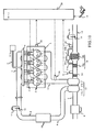
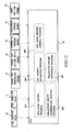
- Fig. 1 is a block diagram that illustrates the schematic construction of an internal combustion engine and its control system including an exhaust gas purification system to which the present invention is applied.
- the internal combustion engine (hereinafter also referred to simply as an engine), generally designated at reference numeral 1, is an internal combustion engine having four cylinders 2.
- the engine 1 is provided with fuel injection valves 3, one for each cylinder 2, for directly injecting fuel into a combustion chamber of each cylinder 2.
- the respective fuel injection valves 3 are connected with an accumulator 4 that serves to accumulate or pressurize the fuel to a predetermined pressure.
- the accumulator 4 is in communication with a fuel pump 6 through a fuel supply pipe 5.
- An intake manifold 7 is connected with the engine or engine proper 1 in such a manner that it is in communication with the combustion chambers of the respective cylinders 2 through intake ports (not illustrated), respectively.
- communication between the combustion chamber of each cylinder 2 and its associated intake port is controlled by opening and closing of an associated intake valve (not illustrated).
- the intake manifold 7 is connected with an intake pipe 8, to which is attached an air flow meter 9 for generating an electric signal corresponding to the mass of intake air flowing through the intake pipe 8.
- a throttle valve 10 is disposed in the intake pipe 8 at a location immediately upstream of the intake manifold 7 for adjusting the flow rate of intake air flowing through the intake pipe 8. Attached to the throttle valve 10 is a throttle actuator 11 in the form of a step motor or the like for driving the throttle valve 10 to open and close.
- centrifugal supercharger (turbocharger) 17 which is adapted to be driven by a drive source in the form of the energy of the exhaust gas from the respective cylinders 2 to compress intake air supplied from the intake pipe 8 to the respective cylinders 2.
- the centrifugal supercharger 17 has a compressor housing 17a arranged on the intake pipe 8 at a location between the air flow meter 9 and the throttle valve 10, and an intercooler 18 for cooling the intake air which has been raised to a high temperature by compression thereof in the compressor housing 17a is installed on the intake pipe 8 at a location downstream of the compressor housing 17a.
- an exhaust manifold 12 is connected with the engine or engine proper 1 with its branch conduits being in communication with the combustion chambers of the respective cylinders 2 through exhaust ports, respectively.
- communication between the combustion chamber of each cylinder 2 and its associated exhaust port is controlled by opening and closing of an associated exhaust valve (not illustrated).
- a fuel addition valve 30 for adding fuel to the exhaust gas flowing in the exhaust manifold 12 is installed on the exhaust manifold 12.
- the exhaust manifold 12 is connected with a turbine housing 17b of the centrifugal supercharger 17, which is in turn connected with one end of an exhaust pipe 13 which is connected at the other end thereof with a muffler (unillustrated).
- an exhaust gas purification device 16 installed on the exhaust pipe 13 at a location downstream of the turbine housing 17b is an exhaust gas purification device 16 in the form of a filter with an NOx catalyst carried thereon, which serves to clean or purify the exhaust gas discharged from the internal combustion engine by occluding and reducing the NOx in the exhaust gas, and which also has the function of collecting particulate matter in the exhaust gas.
- This NOx catalyst has the property to occlude SOx in the exhaust gas, too, and functions as an SOx catalyst.
- a precatalyst 34 having an oxidation function is disposed on the exhaust pipe 13 at a location upstream of the exhaust gas purification device 16.
- an exhaust throttle valve 14 is disposed on the exhaust pipe 13 at a location downstream of the exhaust gas purification device 16 for adjusting the flow rate of the exhaust gas passing through the exhaust pipe 13.
- a throttle actuator 15 is attached to the exhaust throttle valve 14 in the form of a step motor or the like for driving the exhaust throttle valve 14 to open and close.
- the fuel injection valves 3 and the fuel addition valve 30 are operated to open and close by control signals from an electronic control unit (hereinafter referred to as ECU) 20. That is, the injection time and the injection quantity of fuel in the fuel injection valves 3 and the fuel addition valve 30 are controlled for each valve by means of commands from the ECU 20.
- ECU electronice control unit
- an accelerator opening sensor 19 is electrically connected to the ECU 20, so that the ECU 20 receives a signal from the sensor 19 representative of the degree of opening or depression of an accelerator pedal, and calculates, based thereupon, engine output power and the like as required of the internal combustion engine 1.
- a crank position sensor 35 is electrically connected to the ECU 20, so that the ECU 20 receives a signal from the sensor 35 representative of the angle of rotation of an output shaft or crankshaft of the internal combustion engine 1, and calculates, based thereupon, the rotational speed of the internal combustion engine 1 and the like.
- an exhaust gas temperature sensor 31 for detecting the temperature of the exhaust gas flowing into the exhaust gas purification device 16 is disposed on the exhaust pipe 13 at a location between the precatalyst 34 and the exhaust gas purification device 16.
- an exhaust gas air-fuel ratio sensor 32 for detecting the air-fuel ratio of the exhaust gas flowing out of the exhaust gas purification device 16 into the exhaust pipe 13 is installed on the exhaust pipe 13 at a location downstream of the exhaust gas purification device 16.
- the exhaust gas temperature sensor 31 and the exhaust gas air-fuel ratio sensor 32 are electrically connected to the ECU 20, so that the exhaust gas temperature sensor 31 transmits a voltage corresponding to the temperature of the exhaust gas to the ECU 20, whereby the temperature of the exhaust gas is detected by the ECU 20.
- the exhaust gas air-fuel ratio sensor 32 transmits a voltage corresponding to the concentration of oxygen in the exhaust gas to the ECU 20, whereby the air-fuel ratio of the exhaust gas is detected by the ECU 20.
- an upstream side introduction pipe 33a for introducing the exhaust gas into a differential pressure sensor 33 to be described later is connected at its one end with the exhaust pipe 13 at a location between the precatalyst 34 and the exhaust gas purification device 16 and at the other end thereof with the differential pressure sensor 33.
- a downstream side introduction pipe 33b is connected at its one end with the exhaust pipe 13 at a location downstream of the exhaust gas purification device 16, and at the other end thereof with the differential pressure sensor 33.
- the differential pressure sensor 33 transmits a voltage corresponding to a differential pressure between the exhaust gases introduced thereinto from the upstream side introduction pipe 33a and the downstream side introduction pipe 33b to the ECU 20, so that the differential pressure can be detected by the ECU 20.
- the cleaning or purification of the exhaust gas discharged from the internal combustion engine 1 is carried out by the exhaust gas purification system constructed of these sensors, the exhaust gas purification device 16, the fuel addition valve 30 and the like. Accordingly, though the particulate matter contained in the exhaust gas is collected in the exhaust gas purification device 16, it is necessary to remove the collected particulate matter so that the collection ability of the exhaust gas purification device 16 decreases in accordance with the increasing amount of the collected particulate matter.
- the differential pressure detected by the differential pressure sensor 33 increases as the particulate matter collected in the exhaust gas purification device 16 increases. Thus, when the differential pressure becomes equal to or higher than a predetermined pressure, collection ability regeneration control is carried out to remove the particulate matter collected in the exhaust gas purification device 16.
- fuel is added from the fuel addition valve 30 to the exhaust gas, so that the added fuel is oxidized by the precatalyst 34 to raise the temperature of the exhaust gas flowing into the exhaust gas purification device 16 located at the downstream side of the precatalyst 34, whereby the particulate matter collected in the exhaust gas purification device 16 is oxidized.
- the amount and/or injection timing of fuel injected by each of the fuel injection valves 3 to raise the temperature of the exhaust gas flowing into the exhaust gas purification device 16 it is also possible to oxidize the particulate matter collected in the exhaust gas purification device 16.
- the SOx in the exhaust gas is occluded in the exhaust gas purification device 16
- the exhaust gas purification ability such as, for example, NOx purification ability of the exhaust gas purification device 16 deteriorates to a remarkable extent. Accordingly, at that time, the SOx poisoning recovery control of releasing the SOx occluded in the exhaust gas purification device 16 is carried out.
- the SOx poisoning recovery control operates to add fuel from the fuel addition valve 30 to the exhaust gas, whereby the temperature of the exhaust gas flowing into the exhaust gas purification device 16 is caused to rise and at the same time the air-fuel ratio of the exhaust gas is controlled to be a predetermined rich-side air-fuel ratio suitable for the release of the SOx occluded in the exhaust gas purification device 16.
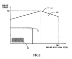
- Fig. 2 is a schematic view that shows these engine load ranges of the internal combustion engine 1, wherein the axis of abscissa represents the rotational speed of the internal combustion engine 1, and the axis of ordinate represents the engine torque of the internal combustion engine 1.
- line L1 represents the change of the engine torque which can resist against the respective rotational speeds of the internal combustion engine 1, and the internal combustion engine 1 in this embodiment has the highest rotational engine speed Ne1 and the greatest or maximum engine torque TQ1. Therefore, the internal combustion engine 1 can resist with respect to the engine load that falls within an area R0 enclosed by the line L1, the axis of ordinate and the axis of abscissa.
- the collection ability regeneration control in the exhaust gas purification device 16 becomes executable when the load of the internal combustion engine 1 (hereinafter also referred to simply as “engine load”) falls within the area R1 (hereinafter referred to as “collection ability regeneration load range R1”), whereas the SOx poisoning recovery control in the exhaust gas purification device 16 becomes executable when the load of the internal combustion engine 1 falls within an area R2 (hereinafter referred to as “SOx release load range R2").
- the relation between them is such that the SOx release load range R2 is greatly limited in comparison with the collection ability regeneration load range R1.
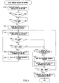
- Fig. 3 is a flow chart showing SOx poisoning recovery control at the time when collection ability regeneration control is executed (hereinafter referred to as "SOx poisoning recovery control during collection ability regeneration").
- SOx poisoning recovery control during collection ability regeneration is executed by the ECU 20.
- step S100 the amount of collection QPM of the particulate matter collected in the exhaust gas purification device 16 is estimated. Specifically, this estimation is made based on a pressure differential between the pressures of the exhaust gas at an upstream side and at a downstream side of the exhaust gas purification device 16 detected by the differential pressure sensor 33, as stated before.
- the control flow proceeds to step S101.
- step S101 it is determined whether the amount of collection QPM estimated in step S100 is more than a predetermined amount of collection QPM1.
- the predetermined amount of collection QPM1 is a threshold for the amount of the particulate matter collected in the exhaust gas purification device 16 above which collection ability regeneration control should be started. Therefore, when it is determined in step S101 that the amount of collection QPM is more than the predetermined amount of collection QPM1, the control flow advances to step S102 so as to perform the following collection ability regeneration control, whereas when it is determined in step S101 that the amount of collection QPM is less than or equal to the predetermined amount of collection QPM1, this means that the particulate matter collection ability of the exhaust gas purification device 16 still remains enough, and hence the processes in steps S100 and S101 are carried out again.
- step S102 it is determined whether the load of the internal combustion engine 1 falls within the collection ability regeneration load range R1.
- QPM > QPM1 in step S101 a determination is made that collection ability regeneration control should be carried out, but in order to perform such control, it is necessary for the load of the internal combustion engine 1 to fall within a predetermined load range, as stated above. Accordingly, in step S102, if it is determined in step S102 that the load of the internal combustion engine 1 falls within the collection ability regeneration load range R1, that is, if the engine load is determined to be in a range in which collection ability regeneration control is permitted or can be executed, the control flow advances to step S103.
- step S102 determines whether the load of the internal combustion engine 1 falls within the collection ability regeneration load range R1 or can not be executed. If it is determined in step S102 that the load of the internal combustion engine 1 does not fall within the collection ability regeneration load range R1, that is, if the engine load is determined to be in a range in which collection ability regeneration control is not permitted or can not be executed, the process in step S102 is repeatedly carried out until the load of the internal combustion engine 1 falls within the collection ability regeneration load range R1.
- step S103 collection ability regeneration control is started so that the particulate matter collected in the exhaust gas purification device 16 is oxidized and removed.
- control is carried out by the addition of fuel to the exhaust gas by means of the fuel addition valve 30 or by the adjustment of the amount and/or injection timing of fuel injected by each of the fuel injection valves 3.
- the temperature of the exhaust gas purification device 16 can be raised to a first predetermined temperature, e.g., 600 °C, whereby the particulate matter in the exhaust gas purification device 16 is oxidized.
- a first predetermined temperature e.g. 600 °C
- step S104 the amount of collection QPM of the particulate matter collected in the exhaust gas purification device 16 is estimated similarly to step S100. That is, the amount of the particulate matter, which has been oxidized and removed by the collection ability regeneration control started in step S103, is taken into consideration, and the amount of the particulate matter, which will be oxidized and removed in the following SOx poisoning recovery control executed in step S107 to be described later, is also taken into consideration.
- the control flow goes to step S105.
- step S105 it is determined whether the load of the internal combustion engine 1 falls within the SOx release load range R2.
- the load of the internal combustion engine 1 In order to perform the SOx poisoning recovery control for the release of the SOx occluded in the exhaust gas purification device 16, it is necessary for the load of the internal combustion engine 1 to fall within a prescribed load range, as mentioned above.
- step S105 if it is determined in step S105 that the load of the internal combustion engine 1 falls within the SOx release load range R2, i.e., if the engine load is in a range in which the SOx poisoning recovery control is permitted or executable, the control flow advances to step S106, whereas if it is determined in step S105 that the load of the internal combustion engine 1 does not fall within the SOx release load range R2, i.e., if the engine load is not in a range in which the SOx poisoning recovery control is executable, the control flow advances to step S108.
- step S106 the collection ability regeneration control started in step S103 is interrupted.
- step S106 the control flow proceeds to step S107.
- step S107 the SOx poisoning recovery control is started, so that the SOx occluded in the exhaust gas purification device 16 is released.
- the temperature of the exhaust gas purification device 16 is raised to a second predetermined temperature, e.g., 650 °C by the addition of fuel to the exhaust gas by means of the fuel addition valve 30, as stated before, and at the same time the air-fuel ratio of the exhaust gas flowing into the exhaust gas purification device 16 is controlled to be a predetermined rich-side air-fuel ratio based on the detection value of the exhaust gas air-fuel ratio sensor 32, so that the release of the occluded SOx from the exhaust gas purification device 16 is carried out.
- the second predetermined temperature may be substantially the same temperature as the first predetermined temperature that is the temperature of the exhaust gas purification device 16 set in step S103, if it is a suitable temperature for the release of the occluded SOx.
- step S107 if the load of the internal combustion engine1 falls within the SOx release load range R2, the collection ability regeneration control, even if being executed, will be interrupted, and the SOx poisoning recovery control will be executed without regard to the amount of the SOx occluded in the exhaust gas purification device 16.
- the processes from step S104 onward are carried out again.
- step S108 it is determined whether the SOx poisoning recovery control started in step S107 is being executed. That is, the advancement of the control flow to step S108 means that the load of the internal combustion engine 1 does not fall within the SOx release load range R2 in step S105. If the SOx poisoning recovery control is carried out in this case, there is fear that the temperature of the exhaust gas purification device 16 might rise excessively or HC might be released to the outside air, as described before, and hence it is determined whether the SOx poisoning recovery control should be stopped in the following processes. Accordingly, when it is determined in step S108 that the SOx poisoning recovery control is being executed, the control flow advances to step S109 where the SOx poisoning recovery control is stopped. After the process in step S109 has been completed, the control process advances to step S110 where the collection ability regeneration control, which has been interrupted in step S106, is restarted or resumed. When the process in step S110 has been completed, the control flow goes to step S111.
- step S108 when it is determined in step S108 that the SOx poisoning recovery control is not being executed, i.e., when the collection ability regeneration control started in step S103 is being continuously executed, the control flow advances to step S111.
- step S111 it is determined whether the amount of particulate matter QPM estimated in step S104 is less than a predetermined amount of collection QPM0.
- the predetermined amount of collection QPM0 is a threshold for the amount of the particulate matter collected in the exhaust gas purification device 16 below which the collection ability regeneration control should be terminated. Therefore, when it is determined in step S111 that the amount of collection QPM is less than the predetermined amount of collection QPM0, the control flow advances to step S112 where the collection ability regeneration control started in step S103 or the collection ability regeneration control restarted in step S110 is terminated, and this control processing is ended.
- step S111 when it is determined in step S111 that the amount of collection QPM is more than or equal to the predetermined amount of collection QPM0, this means that the particulate matter collected in the exhaust gas purification device 16 is not oxidized and removed to a satisfactory extent, and hence the processes from step S104 onward are carried out again.
- control programs shown in Fig. 9 are stored in the ECU 20.
- a collection amount estimation program 501 i.e., a control program for mainly performing the processes of steps S100 and S104
- a collection ability regeneration control program 502 for performing the collection ability regeneration control is stored in the ECU 20, and constitutes a collection ability regeneration control device together with the fuel addition valve 30, the fuel injection valves 3, the exhaust gas temperature sensor 31, etc.
- An SOx poisoning control program 503 for performing the SOx poisoning recovery control is stored in the ECU 20, and constitutes an SOx poisoning recovery control device together with the fuel addition valve 30, the exhaust gas temperature sensor 31, the exhaust gas air-fuel ratio sensor 32, etc.
- An SOx release determination program 504 i.e., a control program for mainly performing the process in step S105 for determining whether the load of the internal combustion engine 1 is in a state in which the SOx poisoning recovery control is permitted or can be performed is stored in the ECU 20, and constitutes an SOx release determination device together with the accelerator opening sensor 19, the crank position sensor 35, etc.
- an SOx release program 505 (i.e., a control program for mainly performing the processes in steps S106 and S107), which serves to interrupt the collection ability regeneration control being executed, and start SOx poisoning recovery control for the release of the occluded SOx when a prescribed condition holds, is stored in the ECU 20, and constitutes an SOx release device together with the fuel addition valve 30, the exhaust gas temperature sensor 31, the exhaust gas air-fuel ratio sensor 32, etc.
- the collection ability regeneration control when the load of the internal combustion engine 1 falls within the SOx release load range R2, the collection ability regeneration control, even if being executed, is interrupted and SOx poisoning recovery control is executed without regard to the amount of the SOx occluded in the exhaust gas purification device 16.
- opportunities to perform the SOx poisoning recovery control are increased, thus making it possible to more quickly recover the exhaust gas purification ability of the exhaust gas purification device 16.
- the execution of the SOx poisoning recovery control depends upon whether the load of the internal combustion engine 1 falls within the SOx release load range R2, but if the SOx poisoning recovery control is executed even in such cases when the amount of SOx occlusion in the exhaust gas purification device 16 is so limited as to not influence the exhaust gas purification ability of the exhaust gas purification device 16, or when the amount of SOx occlusion is substantially zero, the air-fuel ratio of the exhaust gas is made to be a rich-side air-fuel ratio, thus giving rise to a fear that fuel economy might deteriorate.
- step S105 in the flow chart shown in Fig. 3, in which it is determined whether the load of the internal combustion engine 1 falls within the SOx release load range R2, the amount of the SOx occluded in the exhaust gas purification device 16 may be estimated, and when it is determined that the amount of SOx occlusion thus estimated is less than a predetermined amount of occlusion, the processes from step S108 onward may be carried out while skipping the processes in steps S106 and S107 even if the load of the internal combustion engine 1 falls within the SOx release load range R2.
- the exhaust gas purification device 16 is constructed such that the NOx catalyst having the property of occluding SOx in addition to NOx is carried on the filter capable of collecting particulate matter
- the filter and the NOx catalyst may be arranged separately or independently from each other. That is, as shown in Fig. 10, the exhaust gas purification device 16 may comprise an SOx catalyst 16a in the form of an NOx catalyst having the property of occluding SOx in addition to NOx, and a filter 16b arranged at a downstream side of the SOx catalyst 16a and capable of collecting particulate matter.
- the collection ability regeneration control serves to add fuel from the fuel addition valve 30 to the exhaust gas in the exhaust pipe 12, so that the added fuel is oxidized by the precatalyst 34 to raise the temperature of the exhaust gas flowing into the filter 16b located downstream of the precatalyst 34, whereby the particulate matter collected in the filter 16b is oxidized. Also, it is possible to oxidize the particulate matter collected in the filter 16b by adjusting the amount and/or injection timing of fuel being injected by each of the fuel injection valves 3 so as to raise the temperature of the exhaust gas flowing into the filter 16b.
- the SOx poisoning recovery control operates to add fuel from the fuel addition valve 30 to the exhaust gas, whereby the temperature of the exhaust gas flowing into the SOx catalyst 16a is caused to rise and at the same time the air-fuel ratio of the exhaust gas is controlled to be the predetermined rich-side air-fuel ratio suitable for the release of the occluded SOx.
- the SOx poisoning recovery control is executed when the load of the internal combustion engine 1 falls within the SOx release load range R2, similarly as stated above.
- the temperature of the exhaust gas purification device 16 is raised to the second predetermined temperature, and the exhaust gas flowing into the exhaust gas purification device 16 is controlled to be a rich-side air-fuel ratio. At that time, a some amount of oxygen is made to remain in the exhaust gas, so that a part of the particulate matter collected in the exhaust gas purification device 16 is oxidized and removed therefrom.
- the temperature of the exhaust gas purification device 16 (or a filter in the case of the exhaust gas purification device 16 comprising an SOx catalyst in the form of an NOx catalyst and the filter which are arranged separately from each other, as shown in Fig. 10) Will rise excessively by the heat of oxidation of the particulate matter, thus giving rise to a fear that the exhaust gas purification device 16 might be subjected to erosion or dissolved loss.
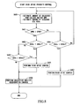
- Fig. 4 is a flow chart showing the control of preventing the erosion of the exhaust gas purification device 16 at the time of SOx poisoning recovery control therein (hereinafter referred to as "erosion prevention control"). Such control is executed by the ECU 20.
- erosion prevention control Such control is executed by the ECU 20.
- the same processes as those in the flow chart of the SOx poisoning recovery control during the collection ability regeneration as shown in Fig. 3 are identified by the same symbols as those employed in Fig. 3, while omitting an explanation thereof.
- step S105 if it is determined in step S105 that the load of the internal combustion engine 1 falls within the SOx release load range R2, the control flow advances to step S200 where it is determined whether the amount of particulate matter QPM estimated in step S104 is less than a predetermined amount of collection QPMOT.
- the predetermined amount of collection QPMOT is a threshold for the amount of the particulate matter collected in the exhaust gas purification device 16 above which it is determined that there is fear that the exhaust gas purification device 16 might erode due to the oxidation heat of the particulate matter collected in the exhaust gas purification device 16 at the time of the SOx poisoning recovery control.
- step S200 when it is determined in step S200 that the amount of collection QPM is less than the predetermined amount of collection QPMOT, this means that there is no fear of the erosion of the exhaust gas purification device 16 due to SOx poisoning recovery control. Accordingly, the SOx poisoning recovery control is carried out in the processes in step S106 and thereafter. On the other hand, if it is determined in step S200 that the amount of collection QPM is more than or equal to the predetermined amount of collection QPMOT, this means that there is a fear of the erosion of the exhaust gas purification device 16 due to the SOx poisoning recovery control. Thus, the control flow advances to step S108, and the SOx poisoning recovery control is not performed.
- a curve LPM represents the change in the amount of the particulate matter collected in the exhaust gas purification device 16. That is, until a point in time T1, particulate matter is successively collected in the exhaust gas purification device 16, so the amount of collection thereof increases, and when the amount of collection reaches QPM1 at time T1, collection ability regeneration control is executed if the load of the internal combustion engine 1 falls within the collection ability regeneration load range R1. That is, the processes in steps S100 through S103 in the erosion prevention control shown in Fig. 4 are carried out.
- the SOx poisoning recovery control is not performed even when the load of the internal combustion engine 1 falls within the SOx release load range R2. Thereafter, at the time when the amount of collection QPM decreases below the predetermined amount of collection QPMOT, i.e., at a point in time T2 in the graph shown in Fig. 5, the SOx poisoning recovery control is performed. That is, the processes in step S200 and thereafter in the erosion prevention control shown in Fig. 4 are performed at time T2.
- the SOx poisoning recovery control or the collection ability regeneration control is executed depending upon the load of the internal combustion engine 1.
- the above-mentioned control according this second embodiment is carried out by control programs which are stored in the ECU 20, as shown in Fig. 9, as in the case of the above-mentioned SOx poisoning recovery control during the collection ability regeneration.
- the SOx release control according to the second embodiment is carried out by an SOx release program 505 (i.e., a control program for mainly performing the processes in steps S200, S106 and S107), which serves to interrupt the collection ability regeneration control being executed, and start SOx poisoning recovery control for the release of the occluded SOx when a prescribed condition holds.
- the SOx release program 505 constitutes an SOx release device together with the fuel addition valve 30, the exhaust gas temperature sensor 31, the exhaust gas air-fuel ratio sensor 32, etc.
- opportunities to perform the SOx poisoning recovery control are increased as in the case of the above-mentioned first embodiment, so that the exhaust gas purification ability of the exhaust gas purification device 16 can be recovered more quickly, and at the same time the erosion of the exhaust gas purification device 16 can be prevented more reliably.
- the SOx released from the exhaust gas purification device 16 when the SOx poisoning recovery control according to the first embodiment is being performed are further reduced by the HC in the exhaust gas and changed into hydrogen sulfide.
- the amount of the released hydrogen sulfide increases, there is fear that the offensive smell of the hydrogen sulfide in the ambient atmosphere might become prominent.
- Fig. 6 is a flow chart showing the control of preventing or suppressing the offensive smell due to the hydrogen sulfide at the time of SOx poisoning recovery control in the exhaust gas purification device 16 (hereinafter referred to as "hydrogen sulfide suppression control").
- the hydrogen sulfide suppression control is executed by the ECU 20.
- the same processes as those in the flow chart of the SOx poisoning recovery control during the collection ability regeneration as shown in Fig. 3 are identified by the same symbols as those employed in Fig. 3, while omitting an explanation thereof.
- step S300 the amount of the hydrogen sulfide QS, which is resulted from the reduction of SOx released from the exhaust gas purification device 16 and emitted into the outside air, is estimated.
- the amount of the hydrogen sulfide QS released in the outside air per unit time is estimated. Specifically, it is estimated from the temperature of the exhaust gas purification device 16 at the time of the SOx poisoning recovery control, the air-fuel ratio of the exhaust gas flowing into the exhaust gas purification device 16, the time elapsed after the SOx poisoning recovery control has been started, or the like.
- step S301 it is determined whether the amount of the released hydrogen sulfide QS estimated in step S300 is less than a predetermined amount of released hydrogen sulfide QS0.
- the predetermined amount of released hydrogen sulfide QS0 is a threshold for the amount of released hydrogen sulfide above which it is determined that the offensive smell due to the hydrogen sulfide is prominent. Therefore, when it is determined in step S301 that the estimated amount of released hydrogen sulfide QS is less than the predetermined amount of released hydrogen sulfide QS0, this means that the offensive smell due to the hydrogen sulfide is not prominent. Accordingly, the processes in step S104 and thereafter are performed so as to continue the SOx poisoning recovery control.
- step S301 when it is determined in step S301 that the estimated amount of released hydrogen sulfide QS is more than or equal to the predetermined amount of released hydrogen sulfide QS0, this means that the offensive smell due to the hydrogen sulfide is prominent.
- the processes in step S109 and thereafter are performed so as to stop the SOx poisoning recovery control thereby to suppress the generation of hydrogen sulfide.
- a curve LSO represents the change in the amount of the SOx released from the exhaust gas purification device 16
- a curve LHS represents the change in the amount of the released hydrogen sulfide due to the SOx released from the exhaust gas purification device 16.
- the SOx poisoning recovery control begins to be executed, and the amount of the SOx released from the exhaust gas purification device 16 increases with time.
- the amount of release of the hydrogen sulfide also increases in accordance with the increasing amount of the released SOx, and the amount of release of the hydrogen sulfide reaches the predetermined amount of released hydrogen sulfide QS0 at time T4.
- the SOx poisoning recovery control is stopped at time T4, that is, the processes in steps S301 and S109 in the hydrogen sulfide suppression control shown in Fig. 6 are carried out.
- the SOx poisoning recovery control is stopped by the process of S105.
- the above control according to this third embodiment is carried out by control programs which are stored in the ECU 20, as shown in Fig. 11.
- a collection amount estimation program 501, a collection ability regeneration control program 502, an SOx poisoning recovery control program 503, and an SOx release determination program 504 in Fig. 11 are similar to those in the above-mentioned SOx poisoning recovery control during collection ability regeneration shown in Fig. 9.
- a hydrogen sulfide release amount estimation program 506 i.e., a control program for mainly performing the process in step S300 in this control
- the SOx release control according to the third embodiment is carried out by an SOx release program 505 (i.e., a control program for mainly performing the processes in steps S106, S107 and S301), which serves to interrupt the collection ability regeneration control being executed, and start SOx poisoning recovery control for the release of the occluded SOx when a prescribed condition holds.
- the SOx release program 505 constitutes an SOx release device together with the fuel addition valve 30, the exhaust gas temperature sensor 31, the exhaust gas air-fuel ratio sensor 32, etc.
- opportunities to perform the SOx poisoning recovery control are increased as in the case of the above-mentioned first embodiment, so that the exhaust gas purification ability of the exhaust gas purification device 16 can be recovered more quickly, and at the same time the release of the hydrogen sulfide can be suppressed, thus making it possible to prevent the offensive smell due to the hydrogen sulfide from becoming prominent.
- so-called rich spike control may be carried out in which the air-fuel ratio of the exhaust gas flowing into the exhaust gas purification device 16 is alternately controlled to be a rich-side air-fuel ratio and a lean-side air-fuel ratio.
- a part of the particulate matter collected in the exhaust gas purification device 16 is oxidized and removed even in the SOx poisoning recovery control, but in the rich spike control, the amount of oxygen in the exhaust gas increases when the air-fuel ratio of the exhaust gas flowing into the exhaust gas purification device 16 becomes a lean-side air-fuel ratio, so a greater amount of the particulate matter collected in the exhaust gas purification device 16 can be oxidized and removed in comparison with the case in which the air-fuel ratio of the exhaust gas is controlled to be a rich-side air-fuel ratio alone.
- Fig. 8 is a flow chart showing the rich spike priority control which is executed by the ECU 20.
- step S400 the amount of the particulate matter QPM collected in the exhaust gas purification device 16 and the amount of the SOx occlusion QSOx occluded in the exhaust gas purification device 16 are estimated. Specifically, the amount of the collected particulate matter QPM is estimated based on a pressure differential between the pressures of the exhaust gas at an upstream side and at a downstream side of the exhaust gas purification device 16 detected by the differential pressure sensor 33, as stated before, and the amount of SOx occlusion QSOx is estimated from the operation time of the internal combustion engine 1 and the amount of injected fuel from the last SOx poisoning recovery control, the concentration of sulfur in the fuel, etc.
- the control flow proceeds to step S401.
- step S401 it is determined whether the amount of collection QPM estimated in step S400 is more than a predetermined amount of collection QPM2.
- the predetermined amount of collection QPM2 is a threshold for the amount of the particulate matter collected in the exhaust gas purification device 16 above which collection ability regeneration control should be started. Therefore, when it is determined in step S401 that the amount of collection QPM is more than the predetermined amount of collection QPM2, the control flow advances to step S402 so as to perform the collection ability regeneration control in the following processes.
- step S401 when it is determined in step S401 that the amount of collection QPM is less than or equal to the predetermined amount of collection QPM2, this means that the particulate matter collection ability of the exhaust gas purification device 16 still remains enough, and hence the control flow proceeds to step S404.
- step S402 it is determined whether the amount of SOx occlusion QSOx estimated in step S400 is more than a predetermined amount of SOx occlusion QSOx1.
- the predetermined amount of SOx occlusion QSOx1 is a threshold for the amount of the SOx occluded in the exhaust gas purification device 16 above which the rich spike control should be started.
- step S402 when it is determined in step S402 that the amount of SOx occlusion QSOx is more than the predetermined amount of SOx occlusion QSOx1, the control flow advances to step S405 so as to perform the rich spike control in the following processes, whereas when it is determined in step S402 that the amount of SOx occlusion QSOx is less than or equal to the predetermined amount of SOx occlusion QSOx1, the control flow advances to step S403.
- step S403 it is determined whether the amount of SOx occlusion QSOx estimated in step S400 is more than a predetermined amount of SOx occlusion QSOx2.
- the predetermined amount of SOx occlusion QSOx2 is a value that is smaller than the above-mentioned predetermined amount of SOx occlusion QSOx1. Therefore, in step S403, it is determined whether the amount of SOx occlusion QSOx estimated in step S400 is a value between the predetermined amount of SOx occlusion QSOx1 and the predetermined amount of SOx occlusion QSOx2.
- the predetermined amount of SOx occlusion QSOx2 is not such a large amount of SOx occlusion above which the rich spike control should promptly be started to quickly release the SOx occluded in the exhaust gas purification device 16, but it is defined as a threshold for the amount of SOx occlusion when lowering of the exhaust gas purification ability of the exhaust gas purification device 16 can be avoided as much as possible by preventively decreasing the amount of SOx occlusion of the exhaust gas purification device 16.
- step S403 when it is determined in step S403 that the amount of SOx occlusion QSOx is more than the predetermined amount of SOx occlusion QSOx2, the control flow advances to step S405 so as to perform the rich spike control in the following process, whereas when it is determined in step S403 that the amount of SOx occlusion QSOx is less than or equal to the predetermined amount of SOx occlusion QSOx2, this means that there is no need to execute the release of the occluded SOx according to the rich spike control, and hence the control flow advances to step S406.
- step S405 the SOx release control according to the rich spike control is carried out so as to release the SOx occluded in the exhaust gas purification device 16.
- this rich spike control particularly when the air-fuel ratio of the exhaust gas flowing into the exhaust gas purification device 16 is made to be a lean-side air-fuel ratio, the particulate matter collected in the exhaust gas purification device 16 is also oxidized and removed.
- step S405 the control flow goes to step S406 where the collection ability regeneration control is executed so as to oxidize and remove the particulate matter remaining in the exhaust gas purification device 16.
- the collection ability regeneration control is also executed so as to oxidize and remove the particulate matter collected in the exhaust gas purification device 16.
- step S404 similar to step S402, it is determined whether the amount of SOx occlusion QSOx estimated in step S400 is more than the predetermined amount of SOx occlusion QSOx1.
- step S404 When it is determined in step S404 that the amount of SOx occlusion QSOx is more than the predetermined amount of SOx occlusion QSOx1, the control flow advances to step S407 so as to perform the rich spike control in the following process, whereas when it is determined in step S404 that the amount of SOx occlusion QSOx is less than or equal to the predetermined amount of SOx occlusion QSOx1, there is no need to perform the collection ability regeneration control and/or the rich spike control, so the processes from step S400 onward are carried out again.
- the rich spike control is performed similar to the process of step S405.
- control programs shown in Fig. 12 are stored in the ECU 20.
- a collection amount estimation program 601 i.e., a control program for mainly performing the processes of step S400 in this control
- a collection ability regeneration control program 602 for performing the collection ability regeneration control is stored in the ECU 20, and constitutes a collection ability regeneration control device together with the fuel addition valve 30, the fuel injection valves 3, the exhaust gas temperature sensor 31, etc.
- a rich spike control program 603 for performing the rich spike control is stored in the ECU 20, and constitutes a rich spike control device together with the fuel addition valve 30, the exhaust gas temperature sensor 31, the exhaust gas air-fuel ratio sensor 32, etc.
- An SOx amount estimation program 604 i.e., a control program for mainly performing the process of step S400 in this control
- for estimating the amount of the SOx occluded in the exhaust gas purification device 16 is stored in the ECU 20, and constitutes an SOx amount estimation device together with the accelerator opening sensor 19, etc.
- a rich spike priority control program 605 (i.e., a control program for mainly performing the processes of steps S402, S403 and S405 of this control) for executing the rich spike control in preference to the collection ability regeneration control when a prescribed condition holds is stored in the ECU 20, and constitutes a rich spike priority control device together with the fuel addition valve 30, the exhaust gas temperature sensor 31, the exhaust gas air-fuel ratio sensor 32, etc.
- the rich spike control has priority over the collection ability regeneration control so that the release of the SOx occluded in the exhaust gas purification device 16 carried out by priority.
- opportunities to release the occluded SOx are increased, thereby making it possible to more quickly recover the exhaust gas purification ability of the exhaust gas purification device 16.
- oxidizing and removing the particulate matter collected in the exhaust gas purification device 16 when the air-fuel ratio of the exhaust gas is controlled to be a lean-side air-fuel ratio in the rich spike control makes it possible to shorten the time required to oxidize and remove the particulate matter by the later performed collection ability regeneration control, whereby deterioration in fuel economy due to the collection ability regeneration control can be reduced or alleviated.
- step S404 when it is determined whether the amount of SOx occlusion QSOx is less than or equal to the predetermined amount of SOx occlusion QSOx1, performing the process similar to step S403 thereafter, whereby the amount of SOx occlusion in the exhaust gas purification device 16 can decrease and lowering of the exhaust gas purification ability of the exhaust gas purification device 16 can be avoided as much as possible.
- an exhaust gas purification system for an internal combustion engine of the present invention opportunities to release the SOx occluded in an exhaust gas purification device are increased, thereby making it possible to more quickly recover the exhaust gas purification ability of the exhaust gas purification device.
Applications Claiming Priority (2)
| Application Number | Priority Date | Filing Date | Title |
|---|---|---|---|
| JP2003135921 | 2003-05-14 | ||
| JP2003135921A JP2004339993A (ja) | 2003-05-14 | 2003-05-14 | 内燃機関の排気浄化システム |
Publications (2)
| Publication Number | Publication Date |
|---|---|
| EP1479900A1 EP1479900A1 (en) | 2004-11-24 |
| EP1479900B1 true EP1479900B1 (en) | 2006-06-21 |
Family
ID=33095364
Family Applications (1)
| Application Number | Title | Priority Date | Filing Date |
|---|---|---|---|
| EP04011572A Expired - Fee Related EP1479900B1 (en) | 2003-05-14 | 2004-05-14 | Exhaust gas purification system for internal combustion engine |
Country Status (4)
| Country | Link |
|---|---|
| US (2) | US7165394B2 (ja) |
| EP (1) | EP1479900B1 (ja) |
| JP (1) | JP2004339993A (ja) |
| DE (1) | DE602004001290T2 (ja) |
Families Citing this family (35)
| Publication number | Priority date | Publication date | Assignee | Title |
|---|---|---|---|---|
| FR2862708B1 (fr) * | 2003-11-24 | 2008-01-18 | Inst Francais Du Petrole | Procede et dispositif de desulfatation d'un piege a oxydes nitriques et de regeneration d'un filtre a particules |
| JP4052286B2 (ja) * | 2004-06-10 | 2008-02-27 | トヨタ自動車株式会社 | 内燃機関の排気浄化装置 |
| JP4046104B2 (ja) * | 2004-06-10 | 2008-02-13 | トヨタ自動車株式会社 | 内燃機関の排気浄化装置 |
| US20100218486A1 (en) * | 2005-08-04 | 2010-09-02 | Mitsubishi Fuso Truck And Bus Corporation | Exhaust gas purification device |
| US7513108B2 (en) | 2005-09-30 | 2009-04-07 | Caterpillar Inc. | Regeneration strategy |
| JP4657074B2 (ja) * | 2005-10-12 | 2011-03-23 | トヨタ自動車株式会社 | 排気浄化装置の制御装置及び排気浄化装置の制御方法 |
| FR2897103B1 (fr) * | 2006-02-09 | 2011-06-10 | Peugeot Citroen Automobiles Sa | Systeme et procede d'elimination de sox (oxyde de soufre), module d'arret pour ce systeme |
| FR2897643B1 (fr) * | 2006-02-20 | 2011-09-16 | Renault Sas | Dispositif de depollution des gaz d'echappement d'un moteur a combustion interne |
| EP1837500B1 (de) * | 2006-03-23 | 2010-10-13 | Ford Global Technologies, LLC | Verfahren zur Steuerung einer Abgasnachbehandlung und zur Vorherbestimmung einer zukünftigen Temperatur in einem Partikelfilter einer Brennkraftmaschine |
| JP4702162B2 (ja) * | 2006-04-26 | 2011-06-15 | トヨタ自動車株式会社 | 内燃機関の排気浄化装置 |
| JP4428361B2 (ja) * | 2006-05-24 | 2010-03-10 | トヨタ自動車株式会社 | 内燃機関の排気浄化システム |
| JP4119927B2 (ja) * | 2006-06-19 | 2008-07-16 | トヨタ自動車株式会社 | 内燃機関の排気浄化装置 |
| JP4404073B2 (ja) * | 2006-06-30 | 2010-01-27 | トヨタ自動車株式会社 | 内燃機関の排気浄化装置 |
| DE102006035283B4 (de) * | 2006-07-31 | 2015-07-16 | Robert Bosch Gmbh | Verfahren zur Bestimmung der Schwefelentladung eines NOx-Speicherkatalysators |
| US7707826B2 (en) * | 2006-11-07 | 2010-05-04 | Cummins, Inc. | System for controlling triggering of adsorber regeneration |
| DE602006008969D1 (de) * | 2006-12-22 | 2009-10-15 | Ford Global Tech Llc | Motorsystem und Verfahren zur Regeneration des abgeführten Gases einer Abgasbehandlungsvorrichtung in einem solchen System |
| JP4665914B2 (ja) * | 2007-02-23 | 2011-04-06 | トヨタ自動車株式会社 | 内燃機関の排気浄化装置 |
| JP4665924B2 (ja) * | 2007-03-16 | 2011-04-06 | トヨタ自動車株式会社 | 内燃機関の排気浄化システム |
| US8566780B2 (en) * | 2007-06-26 | 2013-10-22 | Microsoft Corporation | Object model based mapping |
| JP4816599B2 (ja) | 2007-09-04 | 2011-11-16 | トヨタ自動車株式会社 | 内燃機関の排気浄化システム |
| JP4530080B2 (ja) * | 2008-06-20 | 2010-08-25 | トヨタ自動車株式会社 | 内燃機関の制御装置 |
| US8505277B2 (en) * | 2009-08-06 | 2013-08-13 | GM Global Technology Operations LLC | System and methods for controlling selective catalytic reduction systems |
| US20110146245A1 (en) * | 2009-12-22 | 2011-06-23 | Caterpillar Inc. | Sulfur detection routine |
| US8893493B2 (en) * | 2010-01-14 | 2014-11-25 | GM Global Technology Operations LLC | Engine exhaust system and method of operation |
| KR101427919B1 (ko) * | 2012-10-11 | 2014-09-23 | 현대자동차 주식회사 | 차량의 배출가스 정화장치 및 재생방법 |
| KR101683488B1 (ko) * | 2013-11-22 | 2016-12-07 | 현대자동차 주식회사 | 린 녹스 트랩의 탈황 장치 및 방법 |
| US9228468B2 (en) * | 2014-02-04 | 2016-01-05 | Cummins Inc. | Targeted regeneration of a catalyst in an aftertreatment system |
| JP6179505B2 (ja) * | 2014-12-24 | 2017-08-16 | トヨタ自動車株式会社 | 内燃機関の排気浄化システム |
| JP6471854B2 (ja) * | 2015-02-02 | 2019-02-20 | いすゞ自動車株式会社 | 排気浄化システム |
| JP6471857B2 (ja) | 2015-03-03 | 2019-02-20 | いすゞ自動車株式会社 | 排気浄化システム |
| WO2016143902A1 (ja) | 2015-03-11 | 2016-09-15 | いすゞ自動車株式会社 | 排気浄化システム及び排気浄化システムの制御方法 |
| US10309278B2 (en) * | 2017-10-03 | 2019-06-04 | GM Global Technology Operations LLC | Method for desulfurization of selective catalytic reduction devices |
| JP7163585B2 (ja) * | 2018-02-06 | 2022-11-01 | マツダ株式会社 | エンジンの制御装置 |
| JP7178219B2 (ja) * | 2018-09-10 | 2022-11-25 | 三菱重工エンジン&ターボチャージャ株式会社 | 制御装置、排ガス浄化システムおよびエンジンの制御方法 |
| US11035315B2 (en) * | 2019-09-27 | 2021-06-15 | Ford Global Technologies, Llc | Modeling to compensate for HEGO sensor drift |
Family Cites Families (14)
| Publication number | Priority date | Publication date | Assignee | Title |
|---|---|---|---|---|
| JP2727906B2 (ja) | 1993-03-19 | 1998-03-18 | トヨタ自動車株式会社 | 内燃機関の排気浄化装置 |
| JP3899534B2 (ja) | 1995-08-14 | 2007-03-28 | トヨタ自動車株式会社 | ディーゼル機関の排気浄化方法 |
| US5850735A (en) * | 1995-09-11 | 1998-12-22 | Toyota Jidosha Kabushiki Kaisha | Method for purifying exhaust gas of an internal combustion engine |
| WO1998048153A1 (fr) * | 1997-04-24 | 1998-10-29 | Toyota Jidosha Kabushiki Kaisha | Systeme de gestion d'emissions d'echappement pour moteurs a combustion interne |
| JPH11107809A (ja) | 1997-10-03 | 1999-04-20 | Hitachi Ltd | エンジンの制御装置 |
| US6233925B1 (en) * | 1998-08-28 | 2001-05-22 | Toyota Jidosha Kabushiki Kaisha | Exhaust discharge control device for internal combustion engine |
| US6568178B2 (en) * | 2000-03-28 | 2003-05-27 | Toyota Jidosha Kabushiki Kaisha | Device for purifying the exhaust gas of an internal combustion engine |
| JP3494114B2 (ja) | 2000-03-28 | 2004-02-03 | トヨタ自動車株式会社 | 排気ガス浄化方法および排気ガス浄化装置 |
| JP3487269B2 (ja) | 2000-07-24 | 2004-01-13 | トヨタ自動車株式会社 | 内燃機関の排気浄化装置 |
| JP3835241B2 (ja) * | 2001-10-15 | 2006-10-18 | トヨタ自動車株式会社 | 内燃機関の排気浄化装置 |
| JP3800080B2 (ja) | 2001-11-30 | 2006-07-19 | トヨタ自動車株式会社 | 内燃機関の排気浄化装置 |
| JP4175022B2 (ja) * | 2002-05-20 | 2008-11-05 | 日産自動車株式会社 | 内燃機関の排気浄化装置 |
| JP3945350B2 (ja) * | 2002-08-30 | 2007-07-18 | トヨタ自動車株式会社 | 内燃機関の排気浄化装置 |
| JP4029795B2 (ja) * | 2003-07-30 | 2008-01-09 | 日産自動車株式会社 | 内燃機関の燃焼制御装置 |
-
2003
- 2003-05-14 JP JP2003135921A patent/JP2004339993A/ja active Pending
-
2004
- 2004-05-12 US US10/843,290 patent/US7165394B2/en not_active Expired - Fee Related
- 2004-05-14 DE DE602004001290T patent/DE602004001290T2/de not_active Expired - Fee Related
- 2004-05-14 EP EP04011572A patent/EP1479900B1/en not_active Expired - Fee Related
-
2006
- 2006-08-11 US US11/502,521 patent/US7464542B2/en not_active Expired - Fee Related
Also Published As
| Publication number | Publication date |
|---|---|
| US7464542B2 (en) | 2008-12-16 |
| DE602004001290D1 (de) | 2006-08-03 |
| US20050050881A1 (en) | 2005-03-10 |
| DE602004001290T2 (de) | 2007-06-06 |
| US20070000237A1 (en) | 2007-01-04 |
| US7165394B2 (en) | 2007-01-23 |
| JP2004339993A (ja) | 2004-12-02 |
| EP1479900A1 (en) | 2004-11-24 |
Similar Documents
| Publication | Publication Date | Title |
|---|---|---|
| EP1479900B1 (en) | Exhaust gas purification system for internal combustion engine | |
| EP1778954B1 (en) | Exhaust purifying apparatus and exhaust purifying method for internal combustion engine | |
| EP1350934A1 (en) | Exhaust gas purifying method and apparatus for internal combustion engine | |
| JP4314135B2 (ja) | 車載内燃機関の排気浄化装置 | |
| EP1733130A1 (en) | Exhaust gas control apparatus and exhaust gas control method for internal combustion engine | |
| KR101030861B1 (ko) | 내연 기관의 배기 정화 시스템 | |
| EP1925798B1 (en) | Exhaust gas purifying device for an internal combustion engine | |
| EP2196646B1 (en) | Exhaust gas purification system for an internal combustion engine | |
| EP1725747B1 (en) | Exhaust purifying apparatus for internal combustion engine | |
| EP1471219B1 (en) | Exhaust gas cleaning system and SOx poisoning recovery method for internal combustion engine | |
| EP1536120B1 (en) | Exhaust gas control apparatus for internal combustion engine and control method thereof | |
| JP4435300B2 (ja) | 内燃機関の制御装置 | |
| JP4069044B2 (ja) | 内燃機関の排気浄化装置 | |
| JP2009287515A (ja) | 内燃機関の制御装置 | |
| JP4709733B2 (ja) | 内燃機関の排気浄化装置 | |
| EP1515029B1 (en) | Exhaust purification system of an internal combustion engine | |
| JP2004285947A (ja) | 内燃機関の排気浄化装置 | |
| JP4069043B2 (ja) | 内燃機関の排気浄化装置 | |
| JP2008215105A (ja) | ディーゼルエンジン | |
| US20210180488A1 (en) | Exhaust purification system for internal combustion engine | |
| JP2004278405A (ja) | 内燃機関の排気浄化装置 | |
| JP4646868B2 (ja) | 内燃機関の制御装置 | |
| JP2005030272A (ja) | 内燃機関の排気浄化装置 | |
| JP2006170092A (ja) | 内燃機関の制御装置 |
Legal Events
| Date | Code | Title | Description |
|---|---|---|---|
| PUAI | Public reference made under article 153(3) epc to a published international application that has entered the european phase |
Free format text: ORIGINAL CODE: 0009012 |
|
| 17P | Request for examination filed |
Effective date: 20040514 |
|
| AK | Designated contracting states |
Kind code of ref document: A1 Designated state(s): AT BE BG CH CY CZ DE DK EE ES FI FR GB GR HU IE IT LI LU MC NL PL PT RO SE SI SK TR |
|
| AX | Request for extension of the european patent |
Extension state: AL HR LT LV MK |
|
| 17Q | First examination report despatched |
Effective date: 20050111 |
|
| AKX | Designation fees paid |
Designated state(s): DE FR GB |
|
| GRAP | Despatch of communication of intention to grant a patent |
Free format text: ORIGINAL CODE: EPIDOSNIGR1 |
|
| GRAS | Grant fee paid |
Free format text: ORIGINAL CODE: EPIDOSNIGR3 |
|
| GRAA | (expected) grant |
Free format text: ORIGINAL CODE: 0009210 |
|
| AK | Designated contracting states |
Kind code of ref document: B1 Designated state(s): DE FR GB |
|
| REG | Reference to a national code |
Ref country code: GB Ref legal event code: FG4D |
|
| REF | Corresponds to: |
Ref document number: 602004001290 Country of ref document: DE Date of ref document: 20060803 Kind code of ref document: P |
|
| ET | Fr: translation filed | ||
| PLBE | No opposition filed within time limit |
Free format text: ORIGINAL CODE: 0009261 |
|
| STAA | Information on the status of an ep patent application or granted ep patent |
Free format text: STATUS: NO OPPOSITION FILED WITHIN TIME LIMIT |
|
| 26N | No opposition filed |
Effective date: 20070322 |
|
| PGFP | Annual fee paid to national office [announced via postgrant information from national office to epo] |
Ref country code: DE Payment date: 20090511 Year of fee payment: 6 Ref country code: FR Payment date: 20090515 Year of fee payment: 6 |
|
| PGFP | Annual fee paid to national office [announced via postgrant information from national office to epo] |
Ref country code: GB Payment date: 20090513 Year of fee payment: 6 |
|
| GBPC | Gb: european patent ceased through non-payment of renewal fee |
Effective date: 20100514 |
|
| REG | Reference to a national code |
Ref country code: FR Ref legal event code: ST Effective date: 20110131 |
|
| PG25 | Lapsed in a contracting state [announced via postgrant information from national office to epo] |
Ref country code: DE Free format text: LAPSE BECAUSE OF NON-PAYMENT OF DUE FEES Effective date: 20101201 |
|
| PG25 | Lapsed in a contracting state [announced via postgrant information from national office to epo] |
Ref country code: FR Free format text: LAPSE BECAUSE OF NON-PAYMENT OF DUE FEES Effective date: 20100531 |
|
| PG25 | Lapsed in a contracting state [announced via postgrant information from national office to epo] |
Ref country code: GB Free format text: LAPSE BECAUSE OF NON-PAYMENT OF DUE FEES Effective date: 20100514 |