EP1468760A1 - Rohrkokille zum Stranggiessen - Google Patents
Rohrkokille zum Stranggiessen Download PDFInfo
- Publication number
- EP1468760A1 EP1468760A1 EP03008681A EP03008681A EP1468760A1 EP 1468760 A1 EP1468760 A1 EP 1468760A1 EP 03008681 A EP03008681 A EP 03008681A EP 03008681 A EP03008681 A EP 03008681A EP 1468760 A1 EP1468760 A1 EP 1468760A1
- Authority
- EP
- European Patent Office
- Prior art keywords
- copper tube
- support
- support plates
- mold according
- copper
- Prior art date
- Legal status (The legal status is an assumption and is not a legal conclusion. Google has not performed a legal analysis and makes no representation as to the accuracy of the status listed.)
- Granted
Links
- 238000009749 continuous casting Methods 0.000 title claims abstract description 13
- RYGMFSIKBFXOCR-UHFFFAOYSA-N Copper Chemical compound [Cu] RYGMFSIKBFXOCR-UHFFFAOYSA-N 0.000 claims abstract description 115
- 229910052802 copper Inorganic materials 0.000 claims abstract description 115
- 239000010949 copper Substances 0.000 claims abstract description 115
- 238000001816 cooling Methods 0.000 claims abstract description 59
- XLYOFNOQVPJJNP-UHFFFAOYSA-N water Substances O XLYOFNOQVPJJNP-UHFFFAOYSA-N 0.000 claims abstract description 15
- 229910000831 Steel Inorganic materials 0.000 claims abstract description 8
- 239000010959 steel Substances 0.000 claims abstract description 8
- 239000000498 cooling water Substances 0.000 claims description 17
- 239000010410 layer Substances 0.000 claims description 5
- 239000011241 protective layer Substances 0.000 claims description 5
- 239000007769 metal material Substances 0.000 claims description 4
- 230000007797 corrosion Effects 0.000 claims description 3
- 238000005260 corrosion Methods 0.000 claims description 3
- 230000008878 coupling Effects 0.000 claims description 3
- 238000010168 coupling process Methods 0.000 claims description 3
- 238000005859 coupling reaction Methods 0.000 claims description 3
- 230000001681 protective effect Effects 0.000 abstract 2
- 238000005266 casting Methods 0.000 description 7
- 239000000463 material Substances 0.000 description 7
- 230000008901 benefit Effects 0.000 description 6
- 238000003756 stirring Methods 0.000 description 6
- 238000004519 manufacturing process Methods 0.000 description 5
- 238000003754 machining Methods 0.000 description 4
- 238000003801 milling Methods 0.000 description 4
- 238000007747 plating Methods 0.000 description 3
- 241000196324 Embryophyta Species 0.000 description 2
- 239000000853 adhesive Substances 0.000 description 2
- 230000001070 adhesive effect Effects 0.000 description 2
- 230000001419 dependent effect Effects 0.000 description 2
- 239000007788 liquid Substances 0.000 description 2
- 238000012805 post-processing Methods 0.000 description 2
- 238000011084 recovery Methods 0.000 description 2
- 238000005476 soldering Methods 0.000 description 2
- OKTJSMMVPCPJKN-UHFFFAOYSA-N Carbon Chemical compound [C] OKTJSMMVPCPJKN-UHFFFAOYSA-N 0.000 description 1
- VYZAMTAEIAYCRO-UHFFFAOYSA-N Chromium Chemical compound [Cr] VYZAMTAEIAYCRO-UHFFFAOYSA-N 0.000 description 1
- 240000007643 Phytolacca americana Species 0.000 description 1
- 238000004026 adhesive bonding Methods 0.000 description 1
- 229910000963 austenitic stainless steel Inorganic materials 0.000 description 1
- 238000005452 bending Methods 0.000 description 1
- 229910052799 carbon Inorganic materials 0.000 description 1
- 230000008859 change Effects 0.000 description 1
- 239000011248 coating agent Substances 0.000 description 1
- 238000000576 coating method Methods 0.000 description 1
- 238000010622 cold drawing Methods 0.000 description 1
- 239000002131 composite material Substances 0.000 description 1
- 238000010276 construction Methods 0.000 description 1
- 239000002826 coolant Substances 0.000 description 1
- 230000003292 diminished effect Effects 0.000 description 1
- 238000000605 extraction Methods 0.000 description 1
- 238000010438 heat treatment Methods 0.000 description 1
- 230000014759 maintenance of location Effects 0.000 description 1
- 238000005259 measurement Methods 0.000 description 1
- 238000012545 processing Methods 0.000 description 1
- 230000009467 reduction Effects 0.000 description 1
- 230000008439 repair process Effects 0.000 description 1
- 238000007789 sealing Methods 0.000 description 1
- 229910000679 solder Inorganic materials 0.000 description 1
- 230000008646 thermal stress Effects 0.000 description 1
Images


Classifications
-
- B—PERFORMING OPERATIONS; TRANSPORTING
- B22—CASTING; POWDER METALLURGY
- B22D—CASTING OF METALS; CASTING OF OTHER SUBSTANCES BY THE SAME PROCESSES OR DEVICES
- B22D11/00—Continuous casting of metals, i.e. casting in indefinite lengths
- B22D11/04—Continuous casting of metals, i.e. casting in indefinite lengths into open-ended moulds
- B22D11/055—Cooling the moulds
-
- B—PERFORMING OPERATIONS; TRANSPORTING
- B22—CASTING; POWDER METALLURGY
- B22D—CASTING OF METALS; CASTING OF OTHER SUBSTANCES BY THE SAME PROCESSES OR DEVICES
- B22D11/00—Continuous casting of metals, i.e. casting in indefinite lengths
- B22D11/04—Continuous casting of metals, i.e. casting in indefinite lengths into open-ended moulds
-
- B—PERFORMING OPERATIONS; TRANSPORTING
- B22—CASTING; POWDER METALLURGY
- B22D—CASTING OF METALS; CASTING OF OTHER SUBSTANCES BY THE SAME PROCESSES OR DEVICES
- B22D11/00—Continuous casting of metals, i.e. casting in indefinite lengths
-
- B—PERFORMING OPERATIONS; TRANSPORTING
- B22—CASTING; POWDER METALLURGY
- B22D—CASTING OF METALS; CASTING OF OTHER SUBSTANCES BY THE SAME PROCESSES OR DEVICES
- B22D11/00—Continuous casting of metals, i.e. casting in indefinite lengths
- B22D11/10—Supplying or treating molten metal
- B22D11/11—Treating the molten metal
- B22D11/114—Treating the molten metal by using agitating or vibrating means
- B22D11/115—Treating the molten metal by using agitating or vibrating means by using magnetic fields
-
- B—PERFORMING OPERATIONS; TRANSPORTING
- B22—CASTING; POWDER METALLURGY
- B22D—CASTING OF METALS; CASTING OF OTHER SUBSTANCES BY THE SAME PROCESSES OR DEVICES
- B22D11/00—Continuous casting of metals, i.e. casting in indefinite lengths
- B22D11/12—Accessories for subsequent treating or working cast stock in situ
- B22D11/124—Accessories for subsequent treating or working cast stock in situ for cooling
-
- H—ELECTRICITY
- H01—ELECTRIC ELEMENTS
- H01F—MAGNETS; INDUCTANCES; TRANSFORMERS; SELECTION OF MATERIALS FOR THEIR MAGNETIC PROPERTIES
- H01F7/00—Magnets
- H01F7/02—Permanent magnets [PM]
-
- H—ELECTRICITY
- H01—ELECTRIC ELEMENTS
- H01F—MAGNETS; INDUCTANCES; TRANSFORMERS; SELECTION OF MATERIALS FOR THEIR MAGNETIC PROPERTIES
- H01F7/00—Magnets
- H01F7/06—Electromagnets; Actuators including electromagnets
Definitions
- the invention relates to a tubular mold for continuous casting of round and polygonal Billet and billet sections according to the preamble of claim 1 or 2.
- Vorblockqueritese Tube molds used in continuous casting of steel in billets and small blooms.
- Such tube molds consist of a copper tube, which in a water jacket is installed.
- To a circulation cooling with a high To reach the flow velocity of the cooling water is outside the copper tube a tubular displacer with a small gap opposite the copper tube. Between the displacer and the copper pipe, the cooling water on the entire Circumference of the copper pipe with high pressure and high flow velocity up to 10 m / s and more pressed through.
- the copper pipe in the casting operation by the high Temperature differences between the mold cavity side and the cooling water side no damaging deformations suffers
- the copper tubes which are essentially only be held at the lower and upper pipe end by flanges, a minimum wall thickness exhibit. This minimal wall thickness depends on the casting format and is between 8 - 15 mm.
- the cooling capacity of a mold wall or of the entire mold cavity is considered by many Factors influenced. Essential factors are the thermal conductivity of the copper pipe, the wall thickness of the mold wall, the dimensional stability of the mold cavity to Avoid distortion or air gaps between the strand crust and mold wall, etc.
- the aim of the invention is to provide a continuous casting mold for billet and bloom formats create, in particular, a higher cooling performance and thus higher casting speeds allows, without reaching the limits of the thermal capacity of the copper material to poke.
- this mold is in Giess congress a higher Have dimensional stability and thus less abrasive wear on the one hand Passage of the strand crust through the mold and on the other hand a more uniform cooling or produce a better strand quality.
- an emergence Spiesskantiger strand cross sections are avoided.
- the mold should additionally one achieve extended total service life and thus reduce the chill cost per ton of steel.
- the tube mold according to the invention With the tube mold according to the invention, the following advantages can be achieved in continuous casting be achieved.
- the comparison with the prior art lower wall thickness of the Copper pipe provides a higher cooling capacity with corresponding increase in performance Continuous casting plant safe.
- the arranged substantially over the entire circumference Support plates stabilize the geometry of the mold cavity against distortion of the heat-loaded Copper walls of Kokillenrohres, so that on the one hand Kokillenverschleiss reduced and on the other hand, the strand quality, in particular by a more uniform Cooling, is improved.
- An extended Kokillenstandzeit results from diminished thermal stress of the copper material and less abrasive wear between the strand crust and the mold walls.
- the total lifetime is extended but also by reworking in the mold cavity, such as coppering of wear points followed by subsequent machining, etc., where the Copper pipe during the reworking with the support jacket or with the support plates remains connected.
- This facilitates clamping during machining and vibrations of the copper pipe during milling or planing etc. are caused by the Support plates prevents what higher machining speeds with high dimensional accuracy of the mold cavity.
- the whereabouts of the support plates on the copper tube during the repair of the copper pipe but also reduces the dismantling work the water circulation cooling of the mold, which reduces recovery costs.
- the cooling channels can partially into the support plates and in the outer tube shell of the Copper tube be embedded or milled.
- the wall thickness of the copper pipe Reduce by about 30 - 50% in the area of the cooling channels.
- cooling ducts are milled into the copper pipe on the pipe jacket, so can between the cooling channels supporting and connecting ribs without substantial reduction of Cooling capacity can be arranged.
- the cooling channels 65% - 95%, preferably 70% - 80%, of the outer surface claim the copper tube.
- Residual wall thickness of the copper pipe in the area of the cooling channels is about 4 mm to 10 mm set.
- the support plates can be the copper tube playfully and rigidly clamped, or polygonal formats can be used between the individual support plates in the overlaps small column for seals, preferably elastic seals, are provided.
- Such small gaps can be one thermal expansion of the copper pipe walls and / or dimensional tolerances of the copper pipe jacket field.
- the copper pipe on the support plates or supported on the support shell and / or connect with these.
- the pipe jacket of the copper pipe pro Strand side along the corner areas narrow support surfaces and in the middle of the Extruded pages format dependent one or two connecting ribs arranged, the Connecting ribs with retaining devices against movements transverse to the strand axis are provided.
- Such retaining means can be made of, for example, a Dovetail profile, a T-profile for sliding blocks or generally a force or consist positive locking device. Because at a recovery position the mold cavity, the support plates are not removed with advantage, are also solder Adhesive connections applicable.
- the two support plates which are the arcuate Support side walls of the mold, with advantage with flat outer sides provided so that the mold during reworking without tension on a table can be spanned a processing machine.
- the support plates for example, commercially available steel, if the mold is not equipped with an electromagnetic stirring device.
- an electromagnetic stirring device Of the compact construction of the copper tube with its support plates and intervening Cooling channels facilitates the use of electromagnetic stirring devices.
- Other advantages for electromagnetic stirring devices may be due to the choice of materials the support plates are achieved.
- the Support plates or the support jacket made of a readily penetrable for a magnetic field metallic (austenitic steel etc.) or non-metallic (plastic etc.) material be made. Also composites are to be included in the choice of materials.
- the support plates made of a metallic material, so it is from Advantage, if the electrolytic corrosion caused by the cooling water through an the support plates and the copper tube arranged protective layer is prevented.
- a such protective layer can be constructed, for example, by a copper-plating of the support plate become. But it is also possible, the recessed cooling channels in the copper tube to close with a galvanic copper layer.
- the cooling channels in the copper pipe are provided with water supply and discharge lines to the support plates or connected to the support jacket. According to one embodiment, it is of Advantage, if the water supply and discharge lines on the support plates at the upper Kokillenende arranged side by side and by means of a quick coupling with the cooling water system are connectable.
- FIG. 1 and 2 is a Stranggiesskokille for round billets or billets shown.
- a copper tube 3 forms a mold cavity 4.
- This water circulation cooling consists of Cooling channels 6, over the entire circumference and substantially over the entire length of the copper tube 3 are distributed.
- the individual cooling channels 6 are by supporting and connecting ribs 8 and 9 limited, as an additional task, the leadership of the cooling water circuit in the cooling channels 6 from a water supply line 10 to a water discharge line 11 take over.
- a support jacket is shown, which is the copper tube 3 over the entire circumference and over the entire length encloses and the copper pipe 3 on the outer tube jacket 5 via the support ribs 8 is supported.
- the connecting ribs 9 connect the copper tube 3 to the support shell 12.
- the support shell 12 forms with his inner jacket, the outer boundary of the cooling channels. 6
- the cooling channels 6 are embedded in the outer surface of the copper tube 3 and thereby reduce the wall thickness of the copper tube 3 by 20% - 70%, preferably by 30% - 50% compared to the copper tube thickness at the support ribs 8.
- the thinner the Wall thickness of the copper pipe 3 in the region of the cooling channels 6 can be designed to so the heat transfer from the strand to the cooling water, at the same time
- the operating temperature of the copper wall during casting is lower.
- lower Operating temperatures in the copper wall not only reduce the distortion of the Kokillenrohres 3, also the wear such as cracks in the bathroom mirror area or abrasive wear in the lower mold area is thereby reduced.
- Fig. 1 is schematically a stirring coil for stirring the liquid sump at Continuous casting shown in the mold. It can easily be seen that the stirring coil 14 due to the compact structure of the mold and its reduced copper wall thickness very close to the mold cavity 4 and thus opposite magnetic field losses classic molds are reduced in size.
- backing plates are used or the support shell 12 made of a magnetic fields easily penetrable metallic Material, preferably made of austenitic stainless steel. It is but also possible, the support shell 12 or support plates made of non-metallic materials, for example, from carbon laminate, etc., produce.
- FIG. 3 and 4 20 with a mold for square or polygonal billets and Vorblockstrlinde shown.
- a bent copper tube 23 forms a curved one Mold cavity 24 for a circular arc continuous casting machine.
- a water circulation cooling is disposed between the copper tube 23 and support plates 32-32 '' 'in cooling channels 26 support and connecting ribs 28 and 29 are provided.
- the water circulation cooling is designed substantially the same as described in FIGS. 1 and 2.
- the copper tube 23 in FIG. 3 and 4 between four support plates 32 - 32 '' ' forming a support box, clamped.
- the support plates 32 - 32 "'with the copper tube 23rd connected and support ribs 28 may be the outer tube jacket 25 of the copper tube 23 are supported on the support plates 32-32 "', the four support plates 32-32"' are thus closed screwed together a rigid box around the copper tube 23, that each Support plate 32 - 32 "'on an adjacent plate frontally abuts and the other adjacent Plate overlaps.
- symbols 34 are screws or other fasteners indicated.
- the support plates 32 - 32 "' for example, by Dovetail or sliding block guides, clamping screws, threaded bolts, etc. releasably connected to the copper tube 23.
- the copper tube 23 is clamped or supported on the box of the support plates 32 - 32 "at four corner regions 35 with support ribs 28 '
- the copper tube 23 is generally produced by cold drawing and has in the corner regions and in the support ribs 28, 28' resulting from the manufacturing process wall thickness. This wall thickness is substantially dependent on the to be cast strand format and 120 mm is usually in a strand size of 120 x 2 11 mm and mm at 200 x 200 2 16 mm.
- the cooling channels 6, 26 is by milling
- the copper tube 23 has a residual wall thickness of 4 to 10 mm in the area of the cooling channels. 26 an area of 65% - 95%, preferably 70% - 80% e narrow support surfaces 28 'on both sides of the four pipe corners essential. They ensure that the four angles of the copper tube 23 do not distort during the casting operation. As a result, part of the danger of producing spies-edged strands is eliminated.
- connection ribs 29 are provided, which are the copper tube 23 connect with the support plates 32 - 32 "'via retention devices. bending the copper pipe walls toward the mold cavity 24 or laterally Moving transversely to the strand direction can be avoided.
- positive and non-positive connections are conceivable, such as Dovetail profiles or T-profiles for sliding blocks, welded Bolts etc.
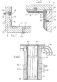
- a support plate 51 overlaps a support plate 52 which abuts with its end face 53 the support plate 51 abuts.
- an elastic Seal 54 arranged in addition to the sealing task against escaping cooling water small tolerances in the outer dimensions of the copper pipe, but also small dimensions the copper pipe wall can catch transversely to the strand extraction direction.
- the support plates 51, 52 With a Protective layer 57 of copper or an electrically non-conductive layer coated become.
- a protective layer 57 for example, the cooling channels 55 'after milling into the copper wall with a galvanically applied copper layer 58 are closed.
- a connecting rib is shown fixed by soldering or gluing connected to the support plate.
- Fig. 6 is an example of a water circulation cooling in cooling channels 61, 61 'along an outer tubular jacket 62 of a copper tube 63 shown.
- a pipe system 64 outside of support plates 65 cooling water is supplied to the cooling channels 61.
- the cooling water is deflected by 180 ° and the cooling channels 61 'forwarded.
- a pipe system 68 the cooling water is removed from the mold.
- 67 schematically a coupling plate is shown, the settling when Mold on a mold table, not shown, the pipe systems 64, 68 to a water supply engage or disengage.
- measuring points 69 are in the outer tube jacket 62 of the copper tube 63 built-in temperature sensor indicated that during the Giess Wilsones the Measure temperatures at various points of copper pipe 63. With such measurements On a screen, a temperature image of the entire copper tube 63 can be graphically displayed being represented.
- the cooling channels in FIGS. 1-6 can by means of various manufacturing processes in the copper pipe are let in. It is possible to use the cooling channels in the outer or Milling the inner tube shell of the copper tube and then with a galvanic to close the applied layer. To the wear resistance in the mold cavity in addition to increase, known in the art known hard chrome plating be provided in the mold cavity.
- FIG. 7 cooling channels 71 in support plates 72, 72 'are arranged.
- a copper tube 70 is in its wall thickness chosen very thin, for example 3 mm - 8 mm.
- Such thin Copper pipes 70 are correspondingly often by support surfaces 74, which are on the support plates 72, 72 'are mounted, supported.
- Mounting surfaces 77 or connecting profiles 78 are usually provided on the copper pipe 70.
- fastening devices such as a connecting bolt 75 or a dovetail profile plate 76 with one or more tie rod (s) 79, the copper tube 70 with the support plates 72, 72 'releasably or firmly connected.
Landscapes
- Engineering & Computer Science (AREA)
- Mechanical Engineering (AREA)
- Physics & Mathematics (AREA)
- Electromagnetism (AREA)
- Power Engineering (AREA)
- Continuous Casting (AREA)
Abstract
Description
- Fig. 1
- einen Längsschnitt durch eine erfindungsgemässe Kokille für runde Stränge,
- Fig. 2
- einen Horizontalschnitt entlang der Linie II - II in Fig. 1,
- Fig. 3
- einen Längsschnitt durch eine Bogenkokille für einen quadratischen Knüppelquerschnitt,
- Fig. 4
- einen Horizontalschnitt entlang der Linie IV - IV in Fig. 3,
- Fig. 5
- einen teilweisen Horizontalschnitt durch eine Kokillenecke,
- Fig. 6
- einen Vertikalschnitt durch ein weiteres Beispiel einer Kokille und
- Fig. 7
- einen teilweisen Horizontalschnitt durch eine Kokillenecke eines weiteren Ausführungsbeispiels
Claims (17)
- Kokille zum Stahlstranggiessen von runden Knüppel- und Vorblockformaten, bestehend aus einem Kupferrohr (3), das einen Formhohlraum (4) bildet und einer Einrichtung zur Kühlung des Kupferrohres mit einer Wasserzirkulationskühlung, dadurch gekennzeichnet, dass das Kupferrohr (3) über den ganzen Umfang und im wesentlichen über die ganze Länge mit einem Stützmantel (12) versehen ist, der das Kupferrohr (3) am äusseren Rohrmantel (5) an Stützflächen (8) abstützt, und dass im Kupferrohr (3) oder im Stützmantel (12) Kühlkanäle (6) zur Führung des Kühlwassers über den ganzen Umfang verteilt und im wesentlichen über die ganze Kokillenlänge angeordnet sind.
- Kokille zum Stahlstranggiessen von polygonalen Knüppel- und Vorblockformaten, vorzugsweise mit rechteckigen Querschnitten, bestehend aus einem Kupferrohr (23), das einen Formhohlraum (24) bildet und einer Einrichtung zur Kühlung des Kupferrohres (23) mit einer Wasserzirkulationskühlung, dadurch gekennzeichnet, dass das Kupferrohr (23) am äusseren Rohrmantel (25) im wesentlichen über den ganzen Umfang und im wesentlichen über die ganze Länge mit Stützplatten (32 - 32'") versehen ist, die mit dem Kupferrohr (23) verbunden sind und die die Wände des Kupferrohres (23) an Stützflächen (28, 28') abstützen und dass im Kupferrohr (23) oder in den Stützplatten (72, 72') Kühlkanäle (26) zur Führung des Kühlwassers über den ganzen Umfang verteilt und im wesentlichen über die ganze Kokillenlänge angeordnet sind.
- Kokille nach Anspruch 1 oder 2, dadurch gekennzeichnet, dass die Kühlkanäle (6, 26) die Wanddicke des Kupferrohres (3, 23) im Bereich der Kühlkanäle (6, 26) um 20 % bis 70 %, vorzugsweise um 30 % bis 50 %, reduzieren.
- Kokille nach Anspruch 1 oder 2, dadurch gekennzeichnet, dass die Kühlkanäle (6, 26) 65 % bis 95 %, vorzugsweise 70 % bis 80 %, der äusseren Oberfläche des Kupferrohres (3, 23) beanspruchen.
- Kokille nach Anspruch 1 oder 2, dadurch gekennzeichnet, dass das Kupferrohr (3, 23) im Bereich der Kühlkanäle (6, 26) eine Restwandstärke von 4 mm bis 10 mm aufweist.
- Kokille nach Anspruch 2, dadurch gekennzeichnet, dass bei rechteckigen Knüppelund Vorblockkokillen vier Stützplatten (32 - 32"') am Kupferrohr (23) lösbar angebracht sind, wobei jede Stützplatte (32 - 32"') an einer benachbarten Platte stirnseitig anschlägt und die andere benachbarte Platte überlappt.
- Kokille nach Anspruch 2, dadurch gekennzeichnet, dass benachbarte Stützplatten (32, 51, 52) in den Eckbereichen des Kupferrohres (23) verschraubt sind und einen rund um das Kupferrohr (23) angeordneten Stützkasten bilden.
- Kokille nach Anspruch 2, dadurch gekennzeichnet, dass in Ueberlappungsspalten zwischen den Stützplatten (51, 52) elastische Dichtungen (54) angeordnet sind, die Ausdehnungen der Kupferrohrwände zulassen.
- Kokille nach Anspruch 1 oder 2, dadurch gekennzeichnet, dass die Kühlkanäle (6, 26) durch Stütz- (8, 28) und/oder Verbindungsrippen (9, 29) begrenzt sind, die das Kupferrohr (3, 23) an den Stützplatten (32) bzw. am Stützmantel (12) abstützen und/oder mit diesen bzw. mit diesem verbinden.
- Kokille nach Anspruch 2, dadurch gekennzeichnet, dass pro Strangseite entlang der Eckbereiche schmale Stützflächen (28') und im Mittelbereich der Kokillenseiten Verbindungsrippen (9, 29, 59) angeordnet sind, wobei die Verbindungsrippen (9, 29, 59) mit Festhalteeinrichtungen gegen Bewegungen quer zur Strangachse versehen sind.
- Kokille nach Anspruch 1 oder 2, dadurch gekennzeichnet, dass die Festhalteeinrichtung aus einem Schwalbenschwanzprofil, einem T-Profil für Gleitsteine oder einer Festklemmeinrichtung etc. besteht.
- Kokille nach Anspruch 2, dadurch gekennzeichnet, dass das Kupferrohr (23) einen bogenförmigen Formhohlraum (24) aufweist und die beiden Stützplatten (32, 32"), die die bogenförmigen Seitenwände des Kupferrohres (23) abstützen, an ihren den bogenförmigen Stützflächen gegenüberliegenden Seiten (36, 36") ebene Begrenzungsflächen aufweisen.
- Kokille nach Anspruch 1 oder 2, dadurch gekennzeichnet, dass im Kupferrohr (3, 23) eingefräste Kühlkanäle (6, 26, 55) mit einer galvanisch erzeugten Kupferschicht (58) verschlossen sind.
- Kokille nach Anspruch 1 oder 2, dadurch gekennzeichnet, dass die Stützplatten (32 - 32"') bzw. der Stützmantel (12) aus einem für Magnetfelder leicht durchdringbaren metallischen, vorzugsweise austenitischem Stahl, oder nichtmetallischen Werkstoff besteht.
- Kokille nach Anspruch 1 oder 2, dadurch gekennzeichnet, dass ausserhalb der Stützplatten (32 - 32"') bzw. des Stützmantels (12) elektromagnetische Spulen (14) angeordnet oder bewegte Dauermagnete in die Stützplatten (32 - 32"') bzw. in den Stützmantel (12) eingebaut sind.
- Kokille nach Anspruch 1 oder 2, dadurch gekennzeichnet, dass zwischen den Stützplatten (32 - 32"', 51, 52) bzw. dem Stützmantel (12) und dem Kupferrohr (3, 23, 56) eine Schutzschicht (57) gegen elektrolytische Korrosion angeordnet ist.
- Kokille nach Anspruch 1 oder 2, dadurch gekennzeichnet, dass die Stützplatten (65) bzw. der Stützmantel (12) mit Külwasserzu- (64) und Abführleitungen (68) versehen sind, die am oberen Kokillenende angeordnet und mittels einer Kupplungsplatte (67) mit dem Kühlwassernetz verbindbar sind.
Priority Applications (22)
| Application Number | Priority Date | Filing Date | Title |
|---|---|---|---|
| EP03008681A EP1468760B1 (de) | 2003-04-16 | 2003-04-16 | Rohrkokille zum Stranggiessen |
| AT03008681T ATE296174T1 (de) | 2003-04-16 | 2003-04-16 | Rohrkokille zum stranggiessen |
| DE50300582T DE50300582D1 (de) | 2003-04-16 | 2003-04-16 | Rohrkokille zum Stranggiessen |
| ES03008681T ES2242119T3 (es) | 2003-04-16 | 2003-04-16 | Lingotera tubular para la colada continua. |
| PT03008681T PT1468760E (pt) | 2003-04-16 | 2003-04-16 | Lingoteira tubular para o vazamento continuo |
| CA002522190A CA2522190C (en) | 2003-04-16 | 2004-04-07 | Tubular mould for continuous casting |
| JP2006505043A JP4610548B2 (ja) | 2003-04-16 | 2004-04-07 | 連続鋳造用管状鋳型 |
| US10/550,373 US7422049B2 (en) | 2003-04-16 | 2004-04-07 | Tubular mould for continuous casting |
| CNB200480010049XA CN100344394C (zh) | 2003-04-16 | 2004-04-07 | 用于连铸的管形锭模 |
| BRPI0409449-2A BRPI0409449B1 (pt) | 2003-04-16 | 2004-04-07 | molde para lingotamento contìnuo de aço. |
| AU2004230206A AU2004230206B2 (en) | 2003-04-16 | 2004-04-07 | Tubular mould for continuous casting |
| MXPA05009765A MXPA05009765A (es) | 2003-04-16 | 2004-04-07 | Lingotera tubular para la colada continua. |
| PCT/EP2004/003712 WO2004091826A1 (de) | 2003-04-16 | 2004-04-07 | Rohrkokille zum stranggiessen |
| KR1020057019234A KR101082901B1 (ko) | 2003-04-16 | 2004-04-07 | 연속 주조용 관형상 주형 |
| RU2005135447/02A RU2316409C2 (ru) | 2003-04-16 | 2004-04-07 | Трубчатый кристаллизатор для непрерывного литья |
| PL377699A PL207539B1 (pl) | 2003-04-16 | 2004-04-07 | Krystalizator rurowy do ciągłego odlewania |
| TW093110157A TWI240660B (en) | 2003-04-16 | 2004-04-12 | Tubular mould for continuous casting |
| MYPI20041352A MY136189A (en) | 2003-04-16 | 2004-04-13 | Tubular mould for continuous casting |
| ARP040101305A AR043879A1 (es) | 2003-04-16 | 2004-04-19 | Lingotera tubular para la colada continua |
| UAA200510838A UA79695C2 (en) | 2003-04-16 | 2004-07-04 | Tubular crystallizer for continuous casting |
| ZA2005/06874A ZA200506874B (en) | 2003-04-16 | 2005-08-26 | Tubular mould for continuous casting |
| EGNA2005000605 EG23891A (en) | 2003-04-16 | 2005-10-02 | Tubular mould for continuous casting |
Applications Claiming Priority (1)
| Application Number | Priority Date | Filing Date | Title |
|---|---|---|---|
| EP03008681A EP1468760B1 (de) | 2003-04-16 | 2003-04-16 | Rohrkokille zum Stranggiessen |
Publications (2)
| Publication Number | Publication Date |
|---|---|
| EP1468760A1 true EP1468760A1 (de) | 2004-10-20 |
| EP1468760B1 EP1468760B1 (de) | 2005-05-25 |
Family
ID=32892888
Family Applications (1)
| Application Number | Title | Priority Date | Filing Date |
|---|---|---|---|
| EP03008681A Expired - Lifetime EP1468760B1 (de) | 2003-04-16 | 2003-04-16 | Rohrkokille zum Stranggiessen |
Country Status (22)
| Country | Link |
|---|---|
| US (1) | US7422049B2 (de) |
| EP (1) | EP1468760B1 (de) |
| JP (1) | JP4610548B2 (de) |
| KR (1) | KR101082901B1 (de) |
| CN (1) | CN100344394C (de) |
| AR (1) | AR043879A1 (de) |
| AT (1) | ATE296174T1 (de) |
| AU (1) | AU2004230206B2 (de) |
| BR (1) | BRPI0409449B1 (de) |
| CA (1) | CA2522190C (de) |
| DE (1) | DE50300582D1 (de) |
| EG (1) | EG23891A (de) |
| ES (1) | ES2242119T3 (de) |
| MX (1) | MXPA05009765A (de) |
| MY (1) | MY136189A (de) |
| PL (1) | PL207539B1 (de) |
| PT (1) | PT1468760E (de) |
| RU (1) | RU2316409C2 (de) |
| TW (1) | TWI240660B (de) |
| UA (1) | UA79695C2 (de) |
| WO (1) | WO2004091826A1 (de) |
| ZA (1) | ZA200506874B (de) |
Cited By (15)
| Publication number | Priority date | Publication date | Assignee | Title |
|---|---|---|---|---|
| EP1792676A1 (de) * | 2005-12-05 | 2007-06-06 | KM Europa Metal Aktiengesellschaft | Kokille zum Stranggiessen von Metall |
| WO2008148465A1 (de) * | 2007-06-04 | 2008-12-11 | Concast Ag | Kokille zum stranggiessen von vorblöcken, brammen und knüppeln |
| EP2055410A1 (de) | 2007-11-01 | 2009-05-06 | KME Germany AG & Co. KG | Flüssigkeitsgekühlte Kokille zum Stranggießen von Metallen |
| DE102010047392A1 (de) * | 2010-10-02 | 2012-04-05 | Egon Evertz Kg (Gmbh & Co.) | Stranggießkokille |
| CN103056317A (zh) * | 2013-01-28 | 2013-04-24 | 青岛云路新能源科技有限公司 | 一种非晶结晶器铜套冷却结构 |
| ITUD20120192A1 (it) * | 2012-11-16 | 2014-05-17 | Danieli Off Mecc | Metodo per la realizzazione di un cristallizzatore per colata continua, e cristallizzatore cosi' ottenuto |
| ITUD20130090A1 (it) * | 2013-06-28 | 2014-12-29 | Danieli Off Mecc | Cristallizzatore per colata continua e procedimento per la sua realizzazione |
| WO2016166215A1 (de) * | 2015-04-16 | 2016-10-20 | Primetals Technologies Austria GmbH | Gestützte rohrkokille für knüppel- und vorblockanlagen |
| EP2620236A3 (de) * | 2012-01-30 | 2017-07-19 | Primetals Technologies Austria GmbH | Durchlaufkokille zum Stranggießen eines Strangs, insbesondere mit Knüppel- oder Vorblockprofil |
| EP3284550A1 (de) | 2016-08-18 | 2018-02-21 | SMS Concast AG | Verfahren zum herstellen einer kokille für das stranggiessen von metallischen produkten, sowie eine kokille |
| EP3406368A1 (de) | 2017-05-23 | 2018-11-28 | SMS Concast AG | Kokille zum stranggiessen von metallischen produkten |
| WO2019007656A1 (de) | 2017-07-03 | 2019-01-10 | Primetals Technologies Austria GmbH | Einbau eines faseroptischen temperatursensors in eine kokille und kokille mit mehreren faseroptischen temperatursensoren |
| WO2020126206A1 (de) | 2018-12-21 | 2020-06-25 | Primetals Technologies Austria GmbH | Kokilleneinheit zum stranggiessen von metallprodukten sowie stranggiessanlage |
| EP3695918A1 (de) | 2019-02-15 | 2020-08-19 | Primetals Technologies Austria GmbH | Kokilleneinheit zum stranggiessen von metallprodukten sowie stranggiessanlage |
| WO2023041814A1 (es) * | 2021-09-20 | 2023-03-23 | Sarralle Steel Melting Plant, S.L. | Conjunto para molde de colada continua |
Families Citing this family (25)
| Publication number | Priority date | Publication date | Assignee | Title |
|---|---|---|---|---|
| EP2025432B2 (de) * | 2007-07-27 | 2017-08-30 | Concast Ag | Verfahren zur Erzeugung von Stahl-Langprodukten durch Stranggiessen und Walzen |
| DE102008007082A1 (de) * | 2007-11-01 | 2009-05-07 | Kme Germany Ag & Co. Kg | Flüssigkeitsgekühlte Kokille zum Stranggießen von Metallen |
| KR101067967B1 (ko) * | 2009-04-27 | 2011-09-26 | 김기창 | 주형지그 |
| JP5423564B2 (ja) * | 2010-04-27 | 2014-02-19 | 新日鐵住金株式会社 | 連続鋳造用鋳型装置 |
| US20120111524A1 (en) * | 2010-11-05 | 2012-05-10 | Schlichting Kevin W | Shot tube plunger for a die casting system |
| ES2695045T3 (es) * | 2011-11-09 | 2018-12-28 | Nippon Steel & Sumitomo Metal Corporation | Aparato de colada continua para acero |
| ITBS20120016A1 (it) * | 2012-01-31 | 2013-08-01 | Sama S R L | Lingottiera di un impianto per colata continua |
| CN102527960A (zh) * | 2012-02-15 | 2012-07-04 | 曲沃县民政福利企业有限公司 | 一种水平连铸新型结晶器 |
| JP5689434B2 (ja) * | 2012-03-23 | 2015-03-25 | 三島光産株式会社 | 連続鋳造用鋳型 |
| JP5896811B2 (ja) * | 2012-04-02 | 2016-03-30 | 株式会社神戸製鋼所 | チタンまたはチタン合金からなる鋳塊の連続鋳造用の鋳型およびこれを備えた連続鋳造装置 |
| CN103341598A (zh) * | 2013-07-19 | 2013-10-09 | 烟台孚信达双金属股份有限公司 | 铜包铝复合材料铸造用结晶器 |
| CN104624990B (zh) * | 2015-02-26 | 2023-08-25 | 周嘉平 | 一种均匀冷却结晶器铜管及其制造方法 |
| KR101613668B1 (ko) * | 2015-04-28 | 2016-04-29 | 주식회사 케이유신소재 | 연속주조용 냉각장치 |
| IT201700027045A1 (it) | 2017-03-10 | 2018-09-10 | Em Moulds S P A A Socio Unico | Cristallizzatore per colata continua e metodo per ottenere lo stesso |
| CN110039013B (zh) * | 2019-04-29 | 2021-01-26 | 攀钢集团攀枝花钢铁研究院有限公司 | 小变形连铸管式结晶器 |
| CN109894585B (zh) * | 2019-04-29 | 2021-01-26 | 攀钢集团攀枝花钢铁研究院有限公司 | 连铸管式结晶器 |
| CN110076326A (zh) * | 2019-05-20 | 2019-08-02 | 沈阳铸造研究所有限公司 | 一种电渣熔铸异形件用结晶器水路控制方法 |
| CN110076303B (zh) * | 2019-05-22 | 2024-05-03 | 中冶赛迪工程技术股份有限公司 | 改变结晶器铜管凸度的方法及可变凸度结晶器铜管 |
| KR102122682B1 (ko) * | 2019-07-29 | 2020-06-12 | 현대제철 주식회사 | 열간압연용 롤의 제조 장치 |
| KR102133133B1 (ko) * | 2019-09-26 | 2020-07-10 | 현대제철 주식회사 | 열간압연용 롤의 제조 장치 |
| CN111468690A (zh) * | 2020-04-22 | 2020-07-31 | 江西耐乐科技协同创新有限公司 | 一种利用感应线圈进行有序结晶的结晶器 |
| RU198654U1 (ru) * | 2020-04-23 | 2020-07-21 | Федеральное государственное бюджетное образовательное учреждение высшего образования "Волгоградский государственный технический университет" (ВолгГТУ) | Трубчатый кристаллизатор |
| CN113441700A (zh) * | 2021-07-30 | 2021-09-28 | 上海睿昇半导体科技有限公司 | 一种冷却水套及其加工方法 |
| CN113579183B (zh) * | 2021-08-02 | 2023-10-27 | 成都冶金实验厂有限公司 | 一种结晶器用的冷却系统 |
| IT202100026519A1 (it) * | 2021-10-06 | 2023-04-06 | Danieli Off Mecc | Cristallizzatore per colata continua |
Citations (2)
| Publication number | Priority date | Publication date | Assignee | Title |
|---|---|---|---|---|
| US4078600A (en) * | 1976-02-03 | 1978-03-14 | Cashdollar Sr Robert E | Continuous casting |
| EP0268143A2 (de) * | 1986-11-19 | 1988-05-25 | Concast Standard Ag | Verfahren und Kokille zum Stranggiessen von Metall-, insbesondere von Stahlsträngen |
Family Cites Families (23)
| Publication number | Priority date | Publication date | Assignee | Title |
|---|---|---|---|---|
| US3667534A (en) * | 1971-03-11 | 1972-06-06 | Sumitomo Metal Ind | Steel ingot making method |
| US3730257A (en) * | 1971-06-24 | 1973-05-01 | Koppers Co Inc | Continuous casting sleeve mold |
| US3763920A (en) * | 1972-03-16 | 1973-10-09 | United States Steel Corp | Water inlet construction for continuous-casting molds |
| DE2613745A1 (de) * | 1976-03-31 | 1977-10-06 | Linde Ag | Waermetauscher |
| FR2423285A1 (fr) * | 1978-04-17 | 1979-11-16 | Siderurgie Fse Inst Rech | Chemise de refroidissement pour lingotiere de coulee continue des metaux |
| JPS6110833Y2 (de) * | 1980-02-27 | 1986-04-07 | ||
| JPS5758953A (en) * | 1980-09-26 | 1982-04-09 | Mitsubishi Heavy Ind Ltd | Block type casting for continuous casting |
| JPS59135850U (ja) * | 1983-02-23 | 1984-09-11 | 三島光産株式会社 | 連続鋳造用鋳型 |
| JPS60176858U (ja) * | 1984-04-26 | 1985-11-22 | 株式会社神戸製鋼所 | 電磁攪拌装置を内蔵した連続鋳造用鋳型 |
| JPS61176445A (ja) * | 1985-01-31 | 1986-08-08 | Sumitomo Heavy Ind Ltd | 連続鋳造装置の鋳型構造 |
| JPS62142453U (de) * | 1986-02-28 | 1987-09-08 | ||
| JPH0160745U (de) * | 1987-10-12 | 1989-04-18 | ||
| JPH01128945U (de) * | 1988-02-24 | 1989-09-01 | ||
| JPH0659523B2 (ja) * | 1988-09-09 | 1994-08-10 | ノムラテクノリサーチ株式会社 | 連続鋳造用鋳型の製造方法 |
| JPH0593644U (ja) * | 1992-05-23 | 1993-12-21 | 神鋼メタルプロダクツ株式会社 | 連続鋳造用チューブラモールド |
| CN2142764Y (zh) * | 1992-12-05 | 1993-09-29 | 章仲禹 | 一种水平连铸方坯的结晶器 |
| CN2151828Y (zh) * | 1992-12-28 | 1994-01-05 | 吉林市钢厂 | 水平连铸小方坯结晶器 |
| CN2206685Y (zh) * | 1994-12-01 | 1995-09-06 | 马鞍山钢铁股份有限公司 | 新型高密封连铸结晶器 |
| CN2236374Y (zh) * | 1995-10-13 | 1996-10-02 | 冶金工业部钢铁研究总院 | 直冷式附加结晶器 |
| CN2301273Y (zh) * | 1997-06-09 | 1998-12-23 | 李建勇 | 一种喷淋式汽化结晶器 |
| CN2300464Y (zh) * | 1997-08-20 | 1998-12-16 | 桂源 | 一种结晶器铜管 |
| CZ295184B6 (cs) * | 1999-08-26 | 2005-06-15 | Concast Standard Ag | Kokila ke kontinuálnímu lití oceli do sochorů a bloků |
| US6374903B1 (en) * | 2000-09-11 | 2002-04-23 | Ag Industries, Inc. | System and process for optimizing cooling in continuous casting mold |
-
2003
- 2003-04-16 PT PT03008681T patent/PT1468760E/pt unknown
- 2003-04-16 DE DE50300582T patent/DE50300582D1/de not_active Expired - Lifetime
- 2003-04-16 EP EP03008681A patent/EP1468760B1/de not_active Expired - Lifetime
- 2003-04-16 AT AT03008681T patent/ATE296174T1/de active
- 2003-04-16 ES ES03008681T patent/ES2242119T3/es not_active Expired - Lifetime
-
2004
- 2004-04-07 RU RU2005135447/02A patent/RU2316409C2/ru not_active IP Right Cessation
- 2004-04-07 PL PL377699A patent/PL207539B1/pl unknown
- 2004-04-07 KR KR1020057019234A patent/KR101082901B1/ko not_active IP Right Cessation
- 2004-04-07 MX MXPA05009765A patent/MXPA05009765A/es active IP Right Grant
- 2004-04-07 AU AU2004230206A patent/AU2004230206B2/en not_active Ceased
- 2004-04-07 CA CA002522190A patent/CA2522190C/en not_active Expired - Fee Related
- 2004-04-07 JP JP2006505043A patent/JP4610548B2/ja not_active Expired - Lifetime
- 2004-04-07 CN CNB200480010049XA patent/CN100344394C/zh not_active Expired - Lifetime
- 2004-04-07 WO PCT/EP2004/003712 patent/WO2004091826A1/de active Application Filing
- 2004-04-07 US US10/550,373 patent/US7422049B2/en not_active Expired - Lifetime
- 2004-04-07 BR BRPI0409449-2A patent/BRPI0409449B1/pt not_active IP Right Cessation
- 2004-04-12 TW TW093110157A patent/TWI240660B/zh not_active IP Right Cessation
- 2004-04-13 MY MYPI20041352A patent/MY136189A/en unknown
- 2004-04-19 AR ARP040101305A patent/AR043879A1/es active IP Right Grant
- 2004-07-04 UA UAA200510838A patent/UA79695C2/uk unknown
-
2005
- 2005-08-26 ZA ZA2005/06874A patent/ZA200506874B/en unknown
- 2005-10-02 EG EGNA2005000605 patent/EG23891A/xx active
Patent Citations (2)
| Publication number | Priority date | Publication date | Assignee | Title |
|---|---|---|---|---|
| US4078600A (en) * | 1976-02-03 | 1978-03-14 | Cashdollar Sr Robert E | Continuous casting |
| EP0268143A2 (de) * | 1986-11-19 | 1988-05-25 | Concast Standard Ag | Verfahren und Kokille zum Stranggiessen von Metall-, insbesondere von Stahlsträngen |
Cited By (23)
| Publication number | Priority date | Publication date | Assignee | Title |
|---|---|---|---|---|
| CN1978091B (zh) * | 2005-12-05 | 2011-04-13 | Km欧洲钢铁股份有限公司 | 用于连铸金属的管式结晶器 |
| EP1792676A1 (de) * | 2005-12-05 | 2007-06-06 | KM Europa Metal Aktiengesellschaft | Kokille zum Stranggiessen von Metall |
| CN101772387B (zh) * | 2007-06-04 | 2013-11-20 | Sms康卡斯特股份公司 | 用于连铸初轧坯、板坯或钢坯的结晶器 |
| WO2008148465A1 (de) * | 2007-06-04 | 2008-12-11 | Concast Ag | Kokille zum stranggiessen von vorblöcken, brammen und knüppeln |
| EP2014393A1 (de) | 2007-06-04 | 2009-01-14 | Concast Ag | Kokille zum Stranggiessen von Vorblöcken, Brammen oder Knüppeln |
| EA017205B1 (ru) * | 2007-06-04 | 2012-10-30 | Смс Конкаст Аг | Кристаллизатор для непрерывной разливки блюмов, слябов или сортовых заготовок |
| EP2055410A1 (de) | 2007-11-01 | 2009-05-06 | KME Germany AG & Co. KG | Flüssigkeitsgekühlte Kokille zum Stranggießen von Metallen |
| DE102010047392A1 (de) * | 2010-10-02 | 2012-04-05 | Egon Evertz Kg (Gmbh & Co.) | Stranggießkokille |
| AT512433B1 (de) * | 2012-01-30 | 2017-08-15 | Primetals Technologies Austria GmbH | Durchlaufkokille zum stranggiessen eines strangs mit knüppel- oder vorblockprofil |
| EP2620236A3 (de) * | 2012-01-30 | 2017-07-19 | Primetals Technologies Austria GmbH | Durchlaufkokille zum Stranggießen eines Strangs, insbesondere mit Knüppel- oder Vorblockprofil |
| ITUD20120192A1 (it) * | 2012-11-16 | 2014-05-17 | Danieli Off Mecc | Metodo per la realizzazione di un cristallizzatore per colata continua, e cristallizzatore cosi' ottenuto |
| CN103056317A (zh) * | 2013-01-28 | 2013-04-24 | 青岛云路新能源科技有限公司 | 一种非晶结晶器铜套冷却结构 |
| WO2014207729A3 (en) * | 2013-06-28 | 2015-04-16 | Danieli & C. Officine Meccaniche S.P.A. | Crystallizer for continuous casting and method for its production |
| WO2014207729A2 (en) | 2013-06-28 | 2014-12-31 | Danieli & C. Officine Meccaniche S.P.A. | Crystallizer for continuous casting and method for its production |
| ITUD20130090A1 (it) * | 2013-06-28 | 2014-12-29 | Danieli Off Mecc | Cristallizzatore per colata continua e procedimento per la sua realizzazione |
| WO2016166215A1 (de) * | 2015-04-16 | 2016-10-20 | Primetals Technologies Austria GmbH | Gestützte rohrkokille für knüppel- und vorblockanlagen |
| EP3284550A1 (de) | 2016-08-18 | 2018-02-21 | SMS Concast AG | Verfahren zum herstellen einer kokille für das stranggiessen von metallischen produkten, sowie eine kokille |
| EP3406368A1 (de) | 2017-05-23 | 2018-11-28 | SMS Concast AG | Kokille zum stranggiessen von metallischen produkten |
| WO2019007656A1 (de) | 2017-07-03 | 2019-01-10 | Primetals Technologies Austria GmbH | Einbau eines faseroptischen temperatursensors in eine kokille und kokille mit mehreren faseroptischen temperatursensoren |
| WO2020126206A1 (de) | 2018-12-21 | 2020-06-25 | Primetals Technologies Austria GmbH | Kokilleneinheit zum stranggiessen von metallprodukten sowie stranggiessanlage |
| KR20210105356A (ko) * | 2018-12-21 | 2021-08-26 | 프리메탈스 테크놀로지스 오스트리아 게엠베하 | 금속 제품의 연속 주조를 위한 금형 유닛 및 연속 주조 설비 |
| EP3695918A1 (de) | 2019-02-15 | 2020-08-19 | Primetals Technologies Austria GmbH | Kokilleneinheit zum stranggiessen von metallprodukten sowie stranggiessanlage |
| WO2023041814A1 (es) * | 2021-09-20 | 2023-03-23 | Sarralle Steel Melting Plant, S.L. | Conjunto para molde de colada continua |
Also Published As
| Publication number | Publication date |
|---|---|
| JP2006523534A (ja) | 2006-10-19 |
| PL377699A1 (pl) | 2006-02-06 |
| KR20050109626A (ko) | 2005-11-21 |
| US20060237161A1 (en) | 2006-10-26 |
| BRPI0409449B1 (pt) | 2011-11-16 |
| DE50300582D1 (de) | 2005-06-30 |
| ATE296174T1 (de) | 2005-06-15 |
| EP1468760B1 (de) | 2005-05-25 |
| ZA200506874B (en) | 2006-05-31 |
| CN100344394C (zh) | 2007-10-24 |
| TWI240660B (en) | 2005-10-01 |
| RU2316409C2 (ru) | 2008-02-10 |
| CA2522190C (en) | 2009-09-29 |
| RU2005135447A (ru) | 2006-03-10 |
| PL207539B1 (pl) | 2010-12-31 |
| UA79695C2 (en) | 2007-07-10 |
| US7422049B2 (en) | 2008-09-09 |
| AR043879A1 (es) | 2005-08-17 |
| KR101082901B1 (ko) | 2011-11-11 |
| CN1774309A (zh) | 2006-05-17 |
| PT1468760E (pt) | 2005-10-31 |
| TW200425975A (en) | 2004-12-01 |
| AU2004230206A1 (en) | 2004-10-28 |
| BRPI0409449A (pt) | 2006-05-02 |
| MY136189A (en) | 2008-08-29 |
| AU2004230206B2 (en) | 2008-12-11 |
| WO2004091826A1 (de) | 2004-10-28 |
| MXPA05009765A (es) | 2006-05-19 |
| ES2242119T3 (es) | 2005-11-01 |
| EG23891A (en) | 2007-12-12 |
| JP4610548B2 (ja) | 2011-01-12 |
| CA2522190A1 (en) | 2004-10-28 |
Similar Documents
| Publication | Publication Date | Title |
|---|---|---|
| EP1468760B1 (de) | Rohrkokille zum Stranggiessen | |
| EP0912271B1 (de) | Flüssigkeitsgekühlte kokille | |
| CH623759A5 (de) | ||
| DE2641261A1 (de) | Kokille mit im kuehlkanal angeordneten induktorspulen | |
| DE60025053T2 (de) | Stranggiessanlage für Stahl | |
| DE2353449C2 (de) | Flüssigkeitsgekühlte Kokille | |
| EP1795281B1 (de) | Stranggiesskokille | |
| EP1007246B1 (de) | Stranggiesskokille | |
| DE2858250C2 (de) | Stranggießkokille | |
| EP1212159B1 (de) | Kokille zum stahlstranggiessen von knüppel- und vorblockformaten | |
| DE10024587A1 (de) | Kühlplatte | |
| EP0268143A2 (de) | Verfahren und Kokille zum Stranggiessen von Metall-, insbesondere von Stahlsträngen | |
| DE2847581C2 (de) | ||
| EP2255140B1 (de) | Kühlelement zur kühlung der feuerfesten auskleidung eines metallurgischen ofens | |
| EP2897746B1 (de) | Vorrichtung zum stranggiessen von metallen | |
| AT526023A1 (de) | Stranggießanlage von Stahl | |
| WO2008017374A1 (de) | KOKILLE ZUM STRANGGIEßEN VON FLÜSSIGEM METALL, INSBESONDERE VON STAHLWERKSTOFFEN | |
| EP1535678B1 (de) | Zusammenbau von Kupferplattenkassetten | |
| DE19716450A1 (de) | Flüssigkeitsgekühlte Kokille | |
| DE10218957B4 (de) | Stranggießkokille für flüssige Metalle, insbesondere für flüssigen Stahl | |
| EP0246423A2 (de) | Verfahren und Vorrichtung zur festen Verbindung von keramischen Formteilen mit Metallen | |
| AT18150U1 (de) | Führungstisch zum geführten Überleiten eines Metallbandes sowie Verfahren zum Betreiben eines derartigen Führungstisches | |
| DE202021004335U1 (de) | Führungstisch zum geführten Überleiten eines Metallbandes | |
| WO1988004586A1 (en) | Process and device for continuous casting of metal bars | |
| DE102009018213A1 (de) | Vakuumpumpengehäuse |
Legal Events
| Date | Code | Title | Description |
|---|---|---|---|
| PUAI | Public reference made under article 153(3) epc to a published international application that has entered the european phase |
Free format text: ORIGINAL CODE: 0009012 |
|
| AK | Designated contracting states |
Kind code of ref document: A1 Designated state(s): AT BE BG CH CY CZ DE DK EE ES FI FR GB GR HU IE IT LI LU MC NL PT RO SE SI SK TR |
|
| AX | Request for extension of the european patent |
Extension state: AL LT LV MK |
|
| GRAP | Despatch of communication of intention to grant a patent |
Free format text: ORIGINAL CODE: EPIDOSNIGR1 |
|
| GRAS | Grant fee paid |
Free format text: ORIGINAL CODE: EPIDOSNIGR3 |
|
| 17P | Request for examination filed |
Effective date: 20041029 |
|
| GRAA | (expected) grant |
Free format text: ORIGINAL CODE: 0009210 |
|
| AK | Designated contracting states |
Kind code of ref document: B1 Designated state(s): AT BE BG CH CY CZ DE DK EE ES FI FR GB GR HU IE IT LI LU MC NL PT RO SE SI SK TR |
|
| AX | Request for extension of the european patent |
Extension state: AL LT LV MK |
|
| PG25 | Lapsed in a contracting state [announced via postgrant information from national office to epo] |
Ref country code: SK Free format text: LAPSE BECAUSE OF FAILURE TO SUBMIT A TRANSLATION OF THE DESCRIPTION OR TO PAY THE FEE WITHIN THE PRESCRIBED TIME-LIMIT Effective date: 20050525 Ref country code: IE Free format text: LAPSE BECAUSE OF FAILURE TO SUBMIT A TRANSLATION OF THE DESCRIPTION OR TO PAY THE FEE WITHIN THE PRESCRIBED TIME-LIMIT Effective date: 20050525 Ref country code: SI Free format text: LAPSE BECAUSE OF FAILURE TO SUBMIT A TRANSLATION OF THE DESCRIPTION OR TO PAY THE FEE WITHIN THE PRESCRIBED TIME-LIMIT Effective date: 20050525 Ref country code: NL Free format text: LAPSE BECAUSE OF FAILURE TO SUBMIT A TRANSLATION OF THE DESCRIPTION OR TO PAY THE FEE WITHIN THE PRESCRIBED TIME-LIMIT Effective date: 20050525 Ref country code: RO Free format text: LAPSE BECAUSE OF FAILURE TO SUBMIT A TRANSLATION OF THE DESCRIPTION OR TO PAY THE FEE WITHIN THE PRESCRIBED TIME-LIMIT Effective date: 20050525 |
|
| REG | Reference to a national code |
Ref country code: GB Ref legal event code: FG4D Free format text: NOT ENGLISH |
|
| REG | Reference to a national code |
Ref country code: SE Ref legal event code: TRGR Ref country code: CH Ref legal event code: EP |
|
| GBT | Gb: translation of ep patent filed (gb section 77(6)(a)/1977) |
Effective date: 20050525 |
|
| REG | Reference to a national code |
Ref country code: IE Ref legal event code: FG4D Free format text: LANGUAGE OF EP DOCUMENT: GERMAN |
|
| REF | Corresponds to: |
Ref document number: 50300582 Country of ref document: DE Date of ref document: 20050630 Kind code of ref document: P |
|
| AKX | Designation fees paid |
Designated state(s): AT BE BG CH CY CZ DE DK EE ES FI FR GB GR HU IE IT LI LU MC NL PT RO SE SI SK TR |
|
| PG25 | Lapsed in a contracting state [announced via postgrant information from national office to epo] |
Ref country code: DK Free format text: LAPSE BECAUSE OF FAILURE TO SUBMIT A TRANSLATION OF THE DESCRIPTION OR TO PAY THE FEE WITHIN THE PRESCRIBED TIME-LIMIT Effective date: 20050825 Ref country code: GR Free format text: LAPSE BECAUSE OF FAILURE TO SUBMIT A TRANSLATION OF THE DESCRIPTION OR TO PAY THE FEE WITHIN THE PRESCRIBED TIME-LIMIT Effective date: 20050825 Ref country code: BG Free format text: LAPSE BECAUSE OF FAILURE TO SUBMIT A TRANSLATION OF THE DESCRIPTION OR TO PAY THE FEE WITHIN THE PRESCRIBED TIME-LIMIT Effective date: 20050825 |
|
| REG | Reference to a national code |
Ref country code: PT Ref legal event code: SC4A Effective date: 20050823 |
|
| REG | Reference to a national code |
Ref country code: ES Ref legal event code: FG2A Ref document number: 2242119 Country of ref document: ES Kind code of ref document: T3 |
|
| PG25 | Lapsed in a contracting state [announced via postgrant information from national office to epo] |
Ref country code: HU Free format text: LAPSE BECAUSE OF FAILURE TO SUBMIT A TRANSLATION OF THE DESCRIPTION OR TO PAY THE FEE WITHIN THE PRESCRIBED TIME-LIMIT Effective date: 20051126 |
|
| NLV1 | Nl: lapsed or annulled due to failure to fulfill the requirements of art. 29p and 29m of the patents act | ||
| REG | Reference to a national code |
Ref country code: IE Ref legal event code: FD4D |
|
| ET | Fr: translation filed | ||
| PLBE | No opposition filed within time limit |
Free format text: ORIGINAL CODE: 0009261 |
|
| STAA | Information on the status of an ep patent application or granted ep patent |
Free format text: STATUS: NO OPPOSITION FILED WITHIN TIME LIMIT |
|
| PG25 | Lapsed in a contracting state [announced via postgrant information from national office to epo] |
Ref country code: MC Free format text: LAPSE BECAUSE OF NON-PAYMENT OF DUE FEES Effective date: 20060430 |
|
| 26N | No opposition filed |
Effective date: 20060228 |
|
| REG | Reference to a national code |
Ref country code: CH Ref legal event code: NV Representative=s name: LUCHS & PARTNER PATENTANWAELTE |
|
| PG25 | Lapsed in a contracting state [announced via postgrant information from national office to epo] |
Ref country code: EE Free format text: LAPSE BECAUSE OF FAILURE TO SUBMIT A TRANSLATION OF THE DESCRIPTION OR TO PAY THE FEE WITHIN THE PRESCRIBED TIME-LIMIT Effective date: 20050525 |
|
| PG25 | Lapsed in a contracting state [announced via postgrant information from national office to epo] |
Ref country code: LU Free format text: LAPSE BECAUSE OF NON-PAYMENT OF DUE FEES Effective date: 20060416 |
|
| PG25 | Lapsed in a contracting state [announced via postgrant information from national office to epo] |
Ref country code: CY Free format text: LAPSE BECAUSE OF FAILURE TO SUBMIT A TRANSLATION OF THE DESCRIPTION OR TO PAY THE FEE WITHIN THE PRESCRIBED TIME-LIMIT Effective date: 20050525 |
|
| PGFP | Annual fee paid to national office [announced via postgrant information from national office to epo] |
Ref country code: GB Payment date: 20130418 Year of fee payment: 11 Ref country code: SE Payment date: 20130418 Year of fee payment: 11 Ref country code: BE Payment date: 20130418 Year of fee payment: 11 |
|
| PGFP | Annual fee paid to national office [announced via postgrant information from national office to epo] |
Ref country code: PT Payment date: 20130416 Year of fee payment: 11 Ref country code: FI Payment date: 20130411 Year of fee payment: 11 Ref country code: FR Payment date: 20130515 Year of fee payment: 11 |
|
| REG | Reference to a national code |
Ref country code: PT Ref legal event code: MM4A Free format text: LAPSE DUE TO NON-PAYMENT OF FEES Effective date: 20141016 |
|
| REG | Reference to a national code |
Ref country code: SE Ref legal event code: EUG |
|
| GBPC | Gb: european patent ceased through non-payment of renewal fee |
Effective date: 20140416 |
|
| REG | Reference to a national code |
Ref country code: FR Ref legal event code: ST Effective date: 20141231 |
|
| PG25 | Lapsed in a contracting state [announced via postgrant information from national office to epo] |
Ref country code: PT Free format text: LAPSE BECAUSE OF NON-PAYMENT OF DUE FEES Effective date: 20141016 Ref country code: GB Free format text: LAPSE BECAUSE OF NON-PAYMENT OF DUE FEES Effective date: 20140416 Ref country code: FI Free format text: LAPSE BECAUSE OF NON-PAYMENT OF DUE FEES Effective date: 20140416 Ref country code: SE Free format text: LAPSE BECAUSE OF NON-PAYMENT OF DUE FEES Effective date: 20140417 |
|
| PG25 | Lapsed in a contracting state [announced via postgrant information from national office to epo] |
Ref country code: FR Free format text: LAPSE BECAUSE OF NON-PAYMENT OF DUE FEES Effective date: 20140430 |
|
| PGFP | Annual fee paid to national office [announced via postgrant information from national office to epo] |
Ref country code: CZ Payment date: 20170324 Year of fee payment: 15 |
|
| PG25 | Lapsed in a contracting state [announced via postgrant information from national office to epo] |
Ref country code: BE Free format text: LAPSE BECAUSE OF NON-PAYMENT OF DUE FEES Effective date: 20140430 |
|
| PG25 | Lapsed in a contracting state [announced via postgrant information from national office to epo] |
Ref country code: CZ Free format text: LAPSE BECAUSE OF NON-PAYMENT OF DUE FEES Effective date: 20180416 |
|
| PGFP | Annual fee paid to national office [announced via postgrant information from national office to epo] |
Ref country code: CH Payment date: 20210503 Year of fee payment: 19 Ref country code: ES Payment date: 20210621 Year of fee payment: 19 Ref country code: TR Payment date: 20210415 Year of fee payment: 19 |
|
| PGFP | Annual fee paid to national office [announced via postgrant information from national office to epo] |
Ref country code: IT Payment date: 20220421 Year of fee payment: 20 Ref country code: DE Payment date: 20220420 Year of fee payment: 20 |
|
| PGFP | Annual fee paid to national office [announced via postgrant information from national office to epo] |
Ref country code: AT Payment date: 20220421 Year of fee payment: 20 |
|
| REG | Reference to a national code |
Ref country code: CH Ref legal event code: PL |
|
| PG25 | Lapsed in a contracting state [announced via postgrant information from national office to epo] |
Ref country code: LI Free format text: LAPSE BECAUSE OF NON-PAYMENT OF DUE FEES Effective date: 20220430 Ref country code: CH Free format text: LAPSE BECAUSE OF NON-PAYMENT OF DUE FEES Effective date: 20220430 |
|
| REG | Reference to a national code |
Ref country code: DE Ref legal event code: R071 Ref document number: 50300582 Country of ref document: DE |
|
| REG | Reference to a national code |
Ref country code: ES Ref legal event code: FD2A Effective date: 20230530 |
|
| REG | Reference to a national code |
Ref country code: AT Ref legal event code: MK07 Ref document number: 296174 Country of ref document: AT Kind code of ref document: T Effective date: 20230416 |
|
| PG25 | Lapsed in a contracting state [announced via postgrant information from national office to epo] |
Ref country code: ES Free format text: LAPSE BECAUSE OF NON-PAYMENT OF DUE FEES Effective date: 20220417 |
|
| PG25 | Lapsed in a contracting state [announced via postgrant information from national office to epo] |
Ref country code: TR Free format text: LAPSE BECAUSE OF NON-PAYMENT OF DUE FEES Effective date: 20220416 |