EP1454752A1 - Tintebehälter - Google Patents
Tintebehälter Download PDFInfo
- Publication number
- EP1454752A1 EP1454752A1 EP04003060A EP04003060A EP1454752A1 EP 1454752 A1 EP1454752 A1 EP 1454752A1 EP 04003060 A EP04003060 A EP 04003060A EP 04003060 A EP04003060 A EP 04003060A EP 1454752 A1 EP1454752 A1 EP 1454752A1
- Authority
- EP
- European Patent Office
- Prior art keywords
- ink container
- container body
- storage means
- ink
- bonded
- Prior art date
- Legal status (The legal status is an assumption and is not a legal conclusion. Google has not performed a legal analysis and makes no representation as to the accuracy of the status listed.)
- Granted
Links
Images


Classifications
-
- B—PERFORMING OPERATIONS; TRANSPORTING
- B41—PRINTING; LINING MACHINES; TYPEWRITERS; STAMPS
- B41J—TYPEWRITERS; SELECTIVE PRINTING MECHANISMS, i.e. MECHANISMS PRINTING OTHERWISE THAN FROM A FORME; CORRECTION OF TYPOGRAPHICAL ERRORS
- B41J2/00—Typewriters or selective printing mechanisms characterised by the printing or marking process for which they are designed
- B41J2/005—Typewriters or selective printing mechanisms characterised by the printing or marking process for which they are designed characterised by bringing liquid or particles selectively into contact with a printing material
- B41J2/01—Ink jet
- B41J2/17—Ink jet characterised by ink handling
- B41J2/175—Ink supply systems ; Circuit parts therefor
- B41J2/17503—Ink cartridges
- B41J2/17559—Cartridge manufacturing
-
- B—PERFORMING OPERATIONS; TRANSPORTING
- B41—PRINTING; LINING MACHINES; TYPEWRITERS; STAMPS
- B41J—TYPEWRITERS; SELECTIVE PRINTING MECHANISMS, i.e. MECHANISMS PRINTING OTHERWISE THAN FROM A FORME; CORRECTION OF TYPOGRAPHICAL ERRORS
- B41J2/00—Typewriters or selective printing mechanisms characterised by the printing or marking process for which they are designed
- B41J2/005—Typewriters or selective printing mechanisms characterised by the printing or marking process for which they are designed characterised by bringing liquid or particles selectively into contact with a printing material
- B41J2/01—Ink jet
- B41J2/015—Ink jet characterised by the jet generation process
- B41J2/04—Ink jet characterised by the jet generation process generating single droplets or particles on demand
- B41J2/045—Ink jet characterised by the jet generation process generating single droplets or particles on demand by pressure, e.g. electromechanical transducers
- B41J2/04501—Control methods or devices therefor, e.g. driver circuits, control circuits
- B41J2/04536—Control methods or devices therefor, e.g. driver circuits, control circuits using history data
-
- B—PERFORMING OPERATIONS; TRANSPORTING
- B41—PRINTING; LINING MACHINES; TYPEWRITERS; STAMPS
- B41J—TYPEWRITERS; SELECTIVE PRINTING MECHANISMS, i.e. MECHANISMS PRINTING OTHERWISE THAN FROM A FORME; CORRECTION OF TYPOGRAPHICAL ERRORS
- B41J2/00—Typewriters or selective printing mechanisms characterised by the printing or marking process for which they are designed
- B41J2/005—Typewriters or selective printing mechanisms characterised by the printing or marking process for which they are designed characterised by bringing liquid or particles selectively into contact with a printing material
- B41J2/01—Ink jet
- B41J2/17—Ink jet characterised by ink handling
- B41J2/175—Ink supply systems ; Circuit parts therefor
- B41J2/17503—Ink cartridges
- B41J2/1752—Mounting within the printer
-
- B—PERFORMING OPERATIONS; TRANSPORTING
- B41—PRINTING; LINING MACHINES; TYPEWRITERS; STAMPS
- B41J—TYPEWRITERS; SELECTIVE PRINTING MECHANISMS, i.e. MECHANISMS PRINTING OTHERWISE THAN FROM A FORME; CORRECTION OF TYPOGRAPHICAL ERRORS
- B41J2/00—Typewriters or selective printing mechanisms characterised by the printing or marking process for which they are designed
- B41J2/005—Typewriters or selective printing mechanisms characterised by the printing or marking process for which they are designed characterised by bringing liquid or particles selectively into contact with a printing material
- B41J2/01—Ink jet
- B41J2/17—Ink jet characterised by ink handling
- B41J2/175—Ink supply systems ; Circuit parts therefor
- B41J2/17503—Ink cartridges
- B41J2/17543—Cartridge presence detection or type identification
- B41J2/17546—Cartridge presence detection or type identification electronically
-
- B—PERFORMING OPERATIONS; TRANSPORTING
- B41—PRINTING; LINING MACHINES; TYPEWRITERS; STAMPS
- B41J—TYPEWRITERS; SELECTIVE PRINTING MECHANISMS, i.e. MECHANISMS PRINTING OTHERWISE THAN FROM A FORME; CORRECTION OF TYPOGRAPHICAL ERRORS
- B41J2/00—Typewriters or selective printing mechanisms characterised by the printing or marking process for which they are designed
- B41J2/005—Typewriters or selective printing mechanisms characterised by the printing or marking process for which they are designed characterised by bringing liquid or particles selectively into contact with a printing material
- B41J2/01—Ink jet
- B41J2/17—Ink jet characterised by ink handling
- B41J2/175—Ink supply systems ; Circuit parts therefor
- B41J2/17503—Ink cartridges
- B41J2/17553—Outer structure
Definitions
- This invention relates to an ink container with a storage means for storing predetermined information.
- the ink container disclosed in Japanese Unexamined Patent Publication No. 10(1998)-133529 is disadvantageous in that since the storage means is embedded in the ink container body, it is difficult to separate the storage means from the ink container body when the empty ink containers are discarded or recycled.
- the ink container disclosed in U.S. Patent No. 6,530,519 is provided with a circuit board which carries a memory IC and directly bonded to the ink container body. Also, in this ink container, it is difficult to separate the memory IC from the ink container body and separation of the memory IC by force can result in damage on the memory IC depending on the state of bonding of the circuit board to the ink container body.
- the primary object of the present invention is to provide an ink container with a storage means for storing predetermined information in which the storage means can be easily removed from the ink container body after ink accommodated therein is consumed.
- an ink container comprising an ink container body and a storage means attached to the ink container body for storing predetermined information, wherein the storage means is bonded to a part of the surface of the ink container body at its surface opposed to the surface of the ink container body over an area not larger than 90% of its surface facing toward said part of the surface of the ink container body.
- the “storage means” may be any storage means so long as information stored therein is readable or readable and writable from external devices.
- the storage means be bonded to the part of the surface of the ink container body by an adhesive, the adhesion of the adhesive be 20N/25mm and at the same time, the storage means be bonded to a part of the surface of the ink container body at its surface opposed to the surface of the ink container body over an area not smaller than 30% and not larger than 90% of its surface facing toward said part of the surface of the ink container body.
- a part or the whole of outer periphery of said surface of the storage means facing toward the part of the surface of the ink container body is preferably not bonded to the surface of the ink container body.
- an ink container comprising an ink container body and a storage means attached to the ink container body for storing predetermined information, wherein the storage means is bonded to a surface of the ink container body at its surface opposed to the surface of the ink container body by way of a protrusion means which is smaller in area than a surface of the storage means facing toward the part of the surface of the ink container body.
- the protrusion means may be formed either integrally with said storage means or the ink container body or as a member separate from said storage means and the ink container body.
- the protrusion means may comprise a plurality of ribs formed at predetermined spaces from each other.
- the ribs are rounded at least one of the end portions respectively in contact with the ink container body and the storage means.
- the protrusion means may comprise a plurality of projections which are brought into contact with the ink container body or the storage means at a point.
- the projections are rounded at least one of the end portions respectively in contact with the ink container body and the storage means.
- the protrusion means is absent in positions opposed to a part or the whole of outer periphery of said surface of the storage means facing toward the part of the surface of the ink container body.
- each of the projections are rounded at least one of the end portions means that at least one of the end portions of each of the ribs has a rounded cross-section, and that the projections are rounded at least one of the end portions means that at least one of the opposite end portions of each of the projections is, for instance, semispherical.
- each of the projections may be spherical as a whole. That is, the end portion may be of any shape so long as the end portion is partly rounded.
- an ink container comprising an ink container body and a storage means attached to the ink container body for storing predetermined information, wherein the storage means is mounted on the ink container body by way of a mounting member which is removably mounted on the ink container body.
- the storage means In the ink container in accordance with the first aspect of the present invention where the storage means is bonded to a part of the surface of the ink container body at its surface opposed to the surface of the ink container body over an area not larger than 90% of its surface facing toward said part of the surface of the ink container body, the storage means can be easily removed from the ink container body and easily separated therefrom after ink accommodated therein is consumed.
- the adhesion of the adhesive is 20N/25mm and at the same time, the storage means is bonded to a part of the surface of the ink container body at its surface opposed to the surface of the ink container body over an area not smaller than 30% and not larger than 90% of its surface facing toward said part of the surface of the ink container body, damage on the storage means upon separation of the storage means from the ink container body can be prevented, and at the same time, inadvertent separation of the storage means from the ink container body on impact, which can result in communication trouble in a stencil printer or the like, can be prevented.
- the storage means can be removed from the ink container body by inserting a removal member from the outer periphery of the surface of the storage means which is not bonded to the surface of the ink container body and accordingly the storage means can be more easily removed from the ink container body.
- the storage means In the ink container in accordance with the second aspect of the present invention where the storage means is bonded to a surface of the ink container body at its surface opposed to the surface of the ink container body by way of a protrusion means which is smaller in area than a surface of the storage means facing toward the part of the surface of the ink container body, the storage means can be easily removed from the ink container body and easily separated therefrom after ink accommodated therein is consumed as in the ink container in accordance with the first aspect.
- the protrusion means comprises a plurality of ribs formed at predetermined spaces from each other or a plurality of projections which are brought into contact with the ink container body or the storage means at a point
- the storage means can be stably held in place and at the same time, the storage means can be easily removed from the ink container body after ink accommodated therein is consumed.
- the storage means can be removed from the ink container body by inserting a removal member from the outer periphery of the surface of the storage means which is not bonded to the surface of the ink container body and accordingly the storage means can be more easily removed from the ink container body.
- the storage means can be further easily removed from the ink container body.
- the storage means In the ink container in accordance with the third aspect of the present invention where the storage means is mounted on the ink container body by way of a mounting member which is removably mounted on the ink container body, the storage means can be easily removed from the ink container body and easily separated therefrom after ink accommodated therein is consumed as in the ink containers in accordance with the first and second aspects of the present invention.
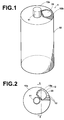
- an ink container 1 comprises an ink container body 10 which is formed of synthetic resin and is substantially cylindrical in shape and a storage means 20 for storing predetermined information.
- An ink discharge port 11 through which ink in the ink container body 10 is discharged is provided on an upper end face 10a of the ink container body 10.
- a memory site 10b where the storage means 20 is provided is formed on a part of the upper end face 10a of the ink container body 10.
- a base sheet on which a memory IC is mounted, that on which a bar code is recorded or that on which characters or symbols are recorded may be employed.
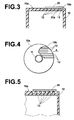
- Figure 2 is a plan view of the ink container 1 and Figure 3 is a cross-sectional view taken along line 3-3 in Figure 2.
- the memory site 10b is formed on a part of the upper end face 10a. That is, a recess is formed in the upper end face 10a, and the storage means 20 are bonded to ribs 12 formed on the bottom surface of the recess as shown in Figure 3.
- the storage means 20 can be easily removed from the ink container body 10 and easily separated therefrom after ink accommodated therein is consumed since the storage means 20 is bonded to the ink container body 10 by way of the ribs 12 formed in the memory site 10b.
- Forming the ribs 12 in this manner is advantageous in that the storage means 20 can be removed from the ink container body 10 by inserting a removal member from the outer periphery of the surface of the storage means 20 which is not bonded to the surface of the ink container body 10 and accordingly the storage means 20 can be more easily removed from the ink container body 10. Further when the ribs 12 are formed so that they extend in the direction of arrow A in which the removal member is inserted as shown in Figure 4, the storage means 20 can be more easily removed from the ink container body 10 as compared with when the ribs 12 are formed so that they extend, for instance, in perpendicular to the direction of arrow A.
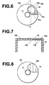
- each rib 12 in contact with the memory means 20 may be rounded as shown in Figure 5.
- the memory means 20 may be bonded to the ink container body 10 by way of a plurality of spot projections 13 formed in the memory site 10b in place of the ribs 12 (12a) as shown in Figure 8.
- the end portion of each spot projection 13 in contact with the memory means 20 may be also rounded. Also in this case, no spot projection 13 may be formed in positions opposed to a part of the outer periphery of the storage means 20 as shown in Figure 8.
- the storage means 20 may be directly bonded to the memory site 10b, for instance, by adhesive without forming a protrusion means (e.g., the ribs 12 (12a) or the spot projections 13). However, in this case, the storage means 20 is bonded to the memory site 10b of the ink container body 10 over an area not larger than 90% of its surface 20a ( Figure 3) facing toward the memory site 10b.
- a protrusion means e.g., the ribs 12 (12a) or the spot projections 13.
- the storage means 20 is bonded to the memory site 10b of the ink container body 10 over an area not larger than 90% of its surface 20a ( Figure 3) facing toward the memory site 10b.
- the storage means 20 is directly bonded to the memory site 10b by adhesive, it is preferred that a part or the whole of outer periphery of the storage means 20 facing toward the memory site 10b of the ink container body 10 be not bonded to the surface of the memory site 10b.
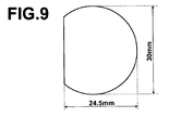
- the bond strengths were measured with the bonding area set to 20% to 100% of the surface 20a of the storage means 20 facing toward the ink container body 10.
- the bond strengths were measured by the use of a SHIMADZU AGS500D (with the load cell for 50N) with the storage means 20 peeled off the ink container body 10 from a state horizontally bonded to the ink container body 10 (a so-called 180 1 peeling).
- the rate of pulling was 300mm/min and the environmental temperature and humidity were 23°C and 50%RH.
- the storage means 20 was as shown in Figure 9, and the bond strength means a maximum bond strength encountered when the storage means 20 was fully peeled off.
- the adhesion of the adhesive for bonding the storage means 20 to the container body 10 was 20N/25mm and the storage means 20 was bonded to the container body 10 by the use of an acrylic adhesive.
- the adhesion of the acrylic adhesive was that to polypropylene.
- the peeling easiness of the storage means 20 was evaluated for each bonding area on the basis of the measured bond strength and tabulated in the following table. bonding area (%) bond strength (N) evaluation 100 21.9 ⁇ 95 16.5 ⁇ 90 10.5 ⁇ 80 6.7 ⁇ 70 6.8 ⁇ 60 4.7 ⁇ 40 4.1 ⁇ 30 3.8 ⁇ 25 2.9 ⁇ 20 2.5 ⁇ ⁇ represents that the storage means is difficult to peel off or is readily peeled off. ⁇ represents that the storage means is easy to peel off and cannot be readily peeled off.
- the bonding area be not smaller than 30% and not larger than 90% of the surface of the storage means 20 facing toward the surface of the ink container body 10 in order to bond the storage means 20 to be easily peeled off the ink container body 10 and not to be readily peeled off the ink container body 10 on impact.
- the storage means 20 may be mounted on the ink container body 10 by way of a mounting member 30 which is removably mounted on the upper end face 10a of the ink container body 10 as shown in Figures 10A and 10B. That is, as shown in Figure 10A, a pair of grooves 14 and a projection 15 are formed in the upper surface 10a of the ink container body 10.
- the mounting member 30 comprises a resin plate 30a conforming to the upper end face 10a of the ink container body 10, and a pair of first fixing portions 30b which are respectively engaged with the grooves 14 and a second fixing portion 30c which is engaged with the projection 15 are formed in the resin plate 30a.
- the storage means 20 is carried by the resin plate 30a and is fixed to the upper end face 10a of the ink container body 10 by mounting the mounting member 30 on the upper end face 10a of the ink container body 10 with the first fixing portions 30b respectively engaged with the grooves 14 and the second fixing portion 30c engaged with the projection 15.
- the second fixing portion 30c is formed of material which is somewhat flexible to allow the second fixing portion 30c to be deformed to be engaged with the projection 15.
- the storage means 20 may be mounted on the ink container body 10 by way of a donut-like mounting member 40 shown in Figure 11. That is, the mounting member 40 comprises a donut-like disk and a rib 40b on the inner surface 40a of the disk.
- the storage means 20 is provided on the rib 40b and the mounting member 40 is removably mounted on the ink container body 10.
- Figure 12A is a view of the mounting member 40 as viewed in the direction of arrow B in Figure 11
- Figure 12B is a cross-sectional view taken along line b-b in Figure 12A of the mounting member 40 when the mounting member 40 is mounted on the ink container body 10 with the storage means 20 provided on the rib 40b.
- the mounting member 40 is provided with protrusions 40c and the mounting member 40 is removably mounted on the ink container body 10 by bringing the protrusions 40c into engagement with recesses formed on a part 16 of the ink container body 10.
- the mounting member 40 is removably mounted on the ink container body 10 by press fitting, the mounting member 40 may be removably mounted on the ink container body 10 by other various methods.
- the mounting member 40 may be removably mounted on the ink container body 10 by screwing.
- the shape of the mounting member need not be limited to the illustrated shape but the mounting member may be of any shape so long as it can be removably mounted on the ink container body 10.
- the memory site 10b is provided on an upper end face 10a of the ink container body 10a, the memory site 10b may be provided on any part of the ink container body 10.
- the ink container body 10 is substantially cylindrical in shape, the ink container body 10 may be of any shape.
Landscapes
- Engineering & Computer Science (AREA)
- Manufacturing & Machinery (AREA)
- Ink Jet (AREA)
- Details Of Rigid Or Semi-Rigid Containers (AREA)
- Inking, Control Or Cleaning Of Printing Machines (AREA)
- Pens And Brushes (AREA)
Applications Claiming Priority (4)
| Application Number | Priority Date | Filing Date | Title |
|---|---|---|---|
| JP2003036090 | 2003-02-14 | ||
| JP2003036090 | 2003-02-14 | ||
| JP2004004234A JP4630551B2 (ja) | 2003-02-14 | 2004-01-09 | インク容器 |
| JP2004004234 | 2004-01-09 |
Publications (2)
| Publication Number | Publication Date |
|---|---|
| EP1454752A1 true EP1454752A1 (de) | 2004-09-08 |
| EP1454752B1 EP1454752B1 (de) | 2007-08-01 |
Family
ID=32828964
Family Applications (1)
| Application Number | Title | Priority Date | Filing Date |
|---|---|---|---|
| EP04003060A Expired - Lifetime EP1454752B1 (de) | 2003-02-14 | 2004-02-11 | Tintebehalter |
Country Status (8)
| Country | Link |
|---|---|
| US (1) | US7168797B2 (de) |
| EP (1) | EP1454752B1 (de) |
| JP (1) | JP4630551B2 (de) |
| KR (1) | KR20040073980A (de) |
| CN (1) | CN1319746C (de) |
| DE (1) | DE602004007839T2 (de) |
| MY (1) | MY140088A (de) |
| TW (1) | TWI251550B (de) |
Cited By (2)
| Publication number | Priority date | Publication date | Assignee | Title |
|---|---|---|---|---|
| WO2008088486A1 (en) * | 2006-12-21 | 2008-07-24 | Eastman Kodak Company | Data and securing mechanism for printing reservoir |
| WO2009047501A1 (en) * | 2007-10-12 | 2009-04-16 | Videojet Technologies Inc. | Ink jet printing |
Families Citing this family (15)
| Publication number | Priority date | Publication date | Assignee | Title |
|---|---|---|---|---|
| JP4795772B2 (ja) | 2005-10-24 | 2011-10-19 | リンテック株式会社 | シート切断用テーブル及びシート貼付装置 |
| GB0720290D0 (en) * | 2007-10-12 | 2007-11-28 | Videojet Technologies Inc | Ink jet printer |
| GB0720289D0 (en) * | 2007-10-12 | 2007-11-28 | Videojet Technologies Inc | Ink jet printer |
| USD712465S1 (en) | 2007-10-12 | 2014-09-02 | Videojet Technologies Inc. | Ink cartridge |
| JP5114263B2 (ja) * | 2008-03-26 | 2013-01-09 | 理想科学工業株式会社 | 記録媒体を備えた開口容器 |
| US8061826B2 (en) * | 2008-07-31 | 2011-11-22 | Static Control Components, Inc. | Methods and devices for remanufacturing an imaging cartridge |
| USD662975S1 (en) * | 2010-11-19 | 2012-07-03 | Domino Printing Sciences Plc | Printer ink cartridge |
| JP5949337B2 (ja) * | 2012-08-31 | 2016-07-06 | セイコーエプソン株式会社 | インク容器 |
| JP6299068B2 (ja) * | 2013-03-05 | 2018-03-28 | セイコーエプソン株式会社 | 液体収容容器 |
| USD714863S1 (en) * | 2013-12-10 | 2014-10-07 | Gfi Innovations, Inc. | Cartridge for ink |
| JP6144210B2 (ja) * | 2014-01-16 | 2017-06-07 | 株式会社キーエンス | インクジェット記録装置、インクジェット記録装置のカートリッジ及びボトル |
| CN107020826B (zh) * | 2016-01-29 | 2019-01-15 | 理想科学工业株式会社 | 墨盒、该盒上的标签剥离方法以及墨盒的再生产方法 |
| JP7135379B2 (ja) | 2018-03-29 | 2022-09-13 | ブラザー工業株式会社 | 液体カートリッジ及びシステム |
| EP3616920B1 (de) * | 2018-08-31 | 2022-02-23 | Brother Kogyo Kabushiki Kaisha | Flüssigkeitskartusche und system mit verwendung davon |
| JP7493991B2 (ja) * | 2020-04-22 | 2024-06-03 | 理想科学工業株式会社 | 部品保持部材 |
Citations (3)
| Publication number | Priority date | Publication date | Assignee | Title |
|---|---|---|---|---|
| US6155678A (en) * | 1999-10-06 | 2000-12-05 | Lexmark International, Inc. | Replaceable ink cartridge for ink jet pen |
| EP1092546A2 (de) * | 1999-10-12 | 2001-04-18 | Seiko Epson Corporation | Tintenpatrone für Tintenstrahldrucksvorrichtung |
| US6322205B1 (en) * | 1997-01-21 | 2001-11-27 | Hewlett-Packard Company | Ink delivery system adapter |
Family Cites Families (27)
| Publication number | Priority date | Publication date | Assignee | Title |
|---|---|---|---|---|
| DE3635737A1 (de) * | 1986-10-21 | 1988-04-28 | Basf Ag | Verfahren zum fixieren einer mehrschichtigen reliefdruckform fuer den flexodruck |
| JP2528061Y2 (ja) * | 1991-08-30 | 1997-03-05 | トーヨーカネツ株式会社 | 物品へのラベル貼付構成 |
| JP3337278B2 (ja) * | 1993-06-24 | 2002-10-21 | 株式会社リコー | 電子機器 |
| US5670557A (en) * | 1994-01-28 | 1997-09-23 | Minnesota Mining And Manufacturing Company | Polymerized microemulsion pressure sensitive adhesive compositions and methods of preparing and using same |
| TW441227B (en) * | 1995-05-26 | 2001-06-16 | E Tec Ag | Contact arrangement for detachably attaching an electric component, especially an integrated circuit to a printed circuit board |
| JP3516553B2 (ja) * | 1995-12-01 | 2004-04-05 | 株式会社リコー | 画像形成装置 |
| GB2307883A (en) * | 1995-12-08 | 1997-06-11 | Gestetner Mfg Ltd | Consumable material management system |
| CH693478A5 (fr) * | 1996-05-10 | 2003-08-15 | E Tec Ag | Socle de connexion de deux composants électriques. |
| JPH10133529A (ja) * | 1996-11-05 | 1998-05-22 | Omron Corp | 交換部品使用状態記録装置及び液体容器 |
| DE69936995T2 (de) * | 1998-03-20 | 2008-05-21 | Nippon Soda Co. Ltd. | Photohärtbare zusammensetzung welche ein iodoniumsalz enthält |
| DE69936947D1 (de) * | 1998-05-13 | 2007-10-04 | Seiko Epson Corp | Tintenpatrone für Tintenstrahlaufzeichnungsgerät |
| JP2000037880A (ja) * | 1998-05-18 | 2000-02-08 | Seiko Epson Corp | インクカ―トリッジ及びインクジェット記録装置及びラベル部材 |
| JPH11348995A (ja) * | 1998-06-02 | 1999-12-21 | Gifu Plast Ind Co Ltd | 搬送用器具 |
| JP3292698B2 (ja) * | 1998-07-10 | 2002-06-17 | 株式会社バンダイ | 電子機器装置 |
| JP2000276054A (ja) * | 1999-03-19 | 2000-10-06 | Canon Inc | ラベル等の貼着機構 |
| JP4106156B2 (ja) * | 1999-07-07 | 2008-06-25 | 理想科学工業株式会社 | 孔版印刷装置 |
| TW541247B (en) * | 2000-01-31 | 2003-07-11 | Hewlett Packard Co | Latch and handle arrangement for a replaceable ink container |
| JP2001219936A (ja) * | 2000-02-10 | 2001-08-14 | Sekisui Seikei Ltd | ラベル貼り付け面を有するプラスチック容器 |
| JP2001353850A (ja) * | 2000-06-14 | 2001-12-25 | Dainippon Printing Co Ltd | 非接触icタグを用いたインキ管理システム等と非接触icタグを設けたインキ容器、印刷インキ取引用非接触icタグ |
| DE10038287A1 (de) * | 2000-08-05 | 2002-02-21 | Itt Mfg Enterprises Inc | Steckkarte für elektronische Geräte |
| GB2354202B (en) * | 2000-08-07 | 2002-09-18 | Dynamic Cassette Int | A printer cartridge kit and method |
| JP2002052802A (ja) * | 2000-08-09 | 2002-02-19 | Dainippon Printing Co Ltd | 孔版印刷機システムと非接触データキャリア付きインキ容器および製版マスタ |
| CA2371040A1 (en) * | 2001-02-09 | 2002-08-09 | Nobuyuki Hatasa | Liquid container and recording apparatus |
| JP2003016415A (ja) * | 2001-06-28 | 2003-01-17 | Toppan Printing Co Ltd | Icメモリタグ付プルタブ |
| JP3666491B2 (ja) * | 2002-03-29 | 2005-06-29 | セイコーエプソン株式会社 | インクカートリッジ及び記録装置 |
| JP2003321032A (ja) * | 2002-04-30 | 2003-11-11 | Kyoraku Co Ltd | 無線情報記憶媒体を備えた容器 |
| US6702215B2 (en) * | 2002-07-03 | 2004-03-09 | Quantum Corporation | Repositionable memory element in a single reel tape cartridge |
-
2004
- 2004-01-09 JP JP2004004234A patent/JP4630551B2/ja not_active Expired - Lifetime
- 2004-02-11 EP EP04003060A patent/EP1454752B1/de not_active Expired - Lifetime
- 2004-02-11 DE DE602004007839T patent/DE602004007839T2/de not_active Expired - Lifetime
- 2004-02-12 TW TW093103336A patent/TWI251550B/zh not_active IP Right Cessation
- 2004-02-13 MY MYPI20040461A patent/MY140088A/en unknown
- 2004-02-13 CN CNB2004100041794A patent/CN1319746C/zh not_active Expired - Lifetime
- 2004-02-13 KR KR1020040009425A patent/KR20040073980A/ko not_active Ceased
- 2004-02-17 US US10/778,196 patent/US7168797B2/en not_active Expired - Lifetime
Patent Citations (3)
| Publication number | Priority date | Publication date | Assignee | Title |
|---|---|---|---|---|
| US6322205B1 (en) * | 1997-01-21 | 2001-11-27 | Hewlett-Packard Company | Ink delivery system adapter |
| US6155678A (en) * | 1999-10-06 | 2000-12-05 | Lexmark International, Inc. | Replaceable ink cartridge for ink jet pen |
| EP1092546A2 (de) * | 1999-10-12 | 2001-04-18 | Seiko Epson Corporation | Tintenpatrone für Tintenstrahldrucksvorrichtung |
Cited By (5)
| Publication number | Priority date | Publication date | Assignee | Title |
|---|---|---|---|---|
| WO2008088486A1 (en) * | 2006-12-21 | 2008-07-24 | Eastman Kodak Company | Data and securing mechanism for printing reservoir |
| CN101622135B (zh) * | 2006-12-21 | 2011-07-06 | 伊斯曼柯达公司 | 用于打印贮存器的数据和固定机构 |
| US7976138B2 (en) | 2006-12-21 | 2011-07-12 | Eastman Kodak Company | Data-providing-component securing mechanism for printing apparatus reservoir |
| WO2009047501A1 (en) * | 2007-10-12 | 2009-04-16 | Videojet Technologies Inc. | Ink jet printing |
| EP2535192A3 (de) * | 2007-10-12 | 2013-05-15 | Videojet Technologies, Inc. | Tintenstrahldrucken |
Also Published As
| Publication number | Publication date |
|---|---|
| TW200422201A (en) | 2004-11-01 |
| DE602004007839D1 (de) | 2007-09-13 |
| KR20040073980A (ko) | 2004-08-21 |
| US7168797B2 (en) | 2007-01-30 |
| DE602004007839T2 (de) | 2008-04-17 |
| CN1520998A (zh) | 2004-08-18 |
| JP4630551B2 (ja) | 2011-02-09 |
| JP2004262235A (ja) | 2004-09-24 |
| EP1454752B1 (de) | 2007-08-01 |
| US20040165046A1 (en) | 2004-08-26 |
| TWI251550B (en) | 2006-03-21 |
| CN1319746C (zh) | 2007-06-06 |
| MY140088A (en) | 2009-11-30 |
Similar Documents
| Publication | Publication Date | Title |
|---|---|---|
| EP1454752A1 (de) | Tintebehälter | |
| US8220909B2 (en) | Ink bag adapter, adapter-equipped ink bag, and printing apparatus | |
| EP0604119B1 (de) | Tintenkassette mit zusammendrückbarem Tintenbehälter | |
| EP1600297B1 (de) | Tintenpatrone zur Benutzung in einem Tintenstrahlaufzeichnungsgerät | |
| CA2616998A1 (en) | Ink cartridge and recording apparatus | |
| EP0756936A2 (de) | Tintenpatrone | |
| US7353831B1 (en) | Container for storing pressed powders | |
| US20120043928A1 (en) | Label attached electric device | |
| US12227011B2 (en) | Print material storage container | |
| JP5996817B1 (ja) | インクカートリッジの再生産方法 | |
| JP2024149426A (ja) | 液体カートリッジ及び液体カートリッジ用保護部材の取り扱い方法 | |
| CA2308634A1 (en) | Spacer | |
| JP7325223B2 (ja) | 製品及びインクカートリッジ並びに製品の生産方法 | |
| US20060012628A1 (en) | Transportation pad for ink cartridge | |
| JP6672107B2 (ja) | インクカートリッジ及びインクカートリッジの再生産方法 | |
| JP2005111917A (ja) | インク容器 | |
| JP6068716B1 (ja) | インクカートリッジの再生産方法 | |
| JP3507037B2 (ja) | ディスク印刷用のディスク移送トレー | |
| CN220262446U (zh) | 一种文件袋 | |
| JP5149595B2 (ja) | 片面柔軟性扁平icタグ及びicタグ付設物品 | |
| JP2017154484A5 (de) | ||
| JP3357320B2 (ja) | メモリカード | |
| US7146878B2 (en) | Ink container opener | |
| JP5996818B1 (ja) | インクカートリッジ及び該カートリッジにおけるタグ分別方法 | |
| CN2799238Y (zh) | 油墨容器 |
Legal Events
| Date | Code | Title | Description |
|---|---|---|---|
| PUAI | Public reference made under article 153(3) epc to a published international application that has entered the european phase |
Free format text: ORIGINAL CODE: 0009012 |
|
| 17P | Request for examination filed |
Effective date: 20040211 |
|
| AK | Designated contracting states |
Kind code of ref document: A1 Designated state(s): AT BE BG CH CY CZ DE DK EE ES FI FR GB GR HU IE IT LI LU MC NL PT RO SE SI SK TR |
|
| AX | Request for extension of the european patent |
Extension state: AL LT LV MK |
|
| AKX | Designation fees paid |
Designated state(s): DE FR GB |
|
| GRAP | Despatch of communication of intention to grant a patent |
Free format text: ORIGINAL CODE: EPIDOSNIGR1 |
|
| GRAS | Grant fee paid |
Free format text: ORIGINAL CODE: EPIDOSNIGR3 |
|
| GRAA | (expected) grant |
Free format text: ORIGINAL CODE: 0009210 |
|
| AK | Designated contracting states |
Kind code of ref document: B1 Designated state(s): DE FR GB |
|
| REG | Reference to a national code |
Ref country code: GB Ref legal event code: FG4D |
|
| REF | Corresponds to: |
Ref document number: 602004007839 Country of ref document: DE Date of ref document: 20070913 Kind code of ref document: P |
|
| ET | Fr: translation filed | ||
| PLBE | No opposition filed within time limit |
Free format text: ORIGINAL CODE: 0009261 |
|
| STAA | Information on the status of an ep patent application or granted ep patent |
Free format text: STATUS: NO OPPOSITION FILED WITHIN TIME LIMIT |
|
| 26N | No opposition filed |
Effective date: 20080506 |
|
| REG | Reference to a national code |
Ref country code: FR Ref legal event code: PLFP Year of fee payment: 13 |
|
| REG | Reference to a national code |
Ref country code: FR Ref legal event code: PLFP Year of fee payment: 14 |
|
| REG | Reference to a national code |
Ref country code: DE Ref legal event code: R082 Ref document number: 602004007839 Country of ref document: DE Representative=s name: KLUNKER IP PATENTANWAELTE PARTG MBB, DE |
|
| REG | Reference to a national code |
Ref country code: FR Ref legal event code: PLFP Year of fee payment: 15 |
|
| PGFP | Annual fee paid to national office [announced via postgrant information from national office to epo] |
Ref country code: FR Payment date: 20230217 Year of fee payment: 20 |
|
| PGFP | Annual fee paid to national office [announced via postgrant information from national office to epo] |
Ref country code: GB Payment date: 20230221 Year of fee payment: 20 Ref country code: DE Payment date: 20230216 Year of fee payment: 20 |
|
| P01 | Opt-out of the competence of the unified patent court (upc) registered |
Effective date: 20230323 |
|
| REG | Reference to a national code |
Ref country code: DE Ref legal event code: R071 Ref document number: 602004007839 Country of ref document: DE |
|
| REG | Reference to a national code |
Ref country code: GB Ref legal event code: PE20 Expiry date: 20240210 |
|
| PG25 | Lapsed in a contracting state [announced via postgrant information from national office to epo] |
Ref country code: GB Free format text: LAPSE BECAUSE OF EXPIRATION OF PROTECTION Effective date: 20240210 |