EP1445158A2 - Motor-Anlasserschalter - Google Patents
Motor-Anlasserschalter Download PDFInfo
- Publication number
- EP1445158A2 EP1445158A2 EP20040002329 EP04002329A EP1445158A2 EP 1445158 A2 EP1445158 A2 EP 1445158A2 EP 20040002329 EP20040002329 EP 20040002329 EP 04002329 A EP04002329 A EP 04002329A EP 1445158 A2 EP1445158 A2 EP 1445158A2
- Authority
- EP
- European Patent Office
- Prior art keywords
- push button
- rotor
- switch device
- engine
- switch
- Prior art date
- Legal status (The legal status is an assumption and is not a legal conclusion. Google has not performed a legal analysis and makes no representation as to the accuracy of the status listed.)
- Granted
Links
Images


Classifications
-
- E—FIXED CONSTRUCTIONS
- E05—LOCKS; KEYS; WINDOW OR DOOR FITTINGS; SAFES
- E05B—LOCKS; ACCESSORIES THEREFOR; HANDCUFFS
- E05B85/00—Details of vehicle locks not provided for in groups E05B77/00 - E05B83/00
- E05B85/02—Lock casings
-
- B—PERFORMING OPERATIONS; TRANSPORTING
- B60—VEHICLES IN GENERAL
- B60R—VEHICLES, VEHICLE FITTINGS, OR VEHICLE PARTS, NOT OTHERWISE PROVIDED FOR
- B60R25/00—Fittings or systems for preventing or indicating unauthorised use or theft of vehicles
- B60R25/20—Means to switch the anti-theft system on or off
- B60R25/2063—Ignition switch geometry
-
- B—PERFORMING OPERATIONS; TRANSPORTING
- B60—VEHICLES IN GENERAL
- B60R—VEHICLES, VEHICLE FITTINGS, OR VEHICLE PARTS, NOT OTHERWISE PROVIDED FOR
- B60R16/00—Electric or fluid circuits specially adapted for vehicles and not otherwise provided for; Arrangement of elements of electric or fluid circuits specially adapted for vehicles and not otherwise provided for
- B60R16/02—Electric or fluid circuits specially adapted for vehicles and not otherwise provided for; Arrangement of elements of electric or fluid circuits specially adapted for vehicles and not otherwise provided for electric constitutive elements
-
- B—PERFORMING OPERATIONS; TRANSPORTING
- B60—VEHICLES IN GENERAL
- B60R—VEHICLES, VEHICLE FITTINGS, OR VEHICLE PARTS, NOT OTHERWISE PROVIDED FOR
- B60R25/00—Fittings or systems for preventing or indicating unauthorised use or theft of vehicles
- B60R25/01—Fittings or systems for preventing or indicating unauthorised use or theft of vehicles operating on vehicle systems or fittings, e.g. on doors, seats or windscreens
- B60R25/04—Fittings or systems for preventing or indicating unauthorised use or theft of vehicles operating on vehicle systems or fittings, e.g. on doors, seats or windscreens operating on the propulsion system, e.g. engine or drive motor
-
- E—FIXED CONSTRUCTIONS
- E05—LOCKS; KEYS; WINDOW OR DOOR FITTINGS; SAFES
- E05B—LOCKS; ACCESSORIES THEREFOR; HANDCUFFS
- E05B85/00—Details of vehicle locks not provided for in groups E05B77/00 - E05B83/00
- E05B85/06—Lock cylinder arrangements
-
- Y—GENERAL TAGGING OF NEW TECHNOLOGICAL DEVELOPMENTS; GENERAL TAGGING OF CROSS-SECTIONAL TECHNOLOGIES SPANNING OVER SEVERAL SECTIONS OF THE IPC; TECHNICAL SUBJECTS COVERED BY FORMER USPC CROSS-REFERENCE ART COLLECTIONS [XRACs] AND DIGESTS
- Y10—TECHNICAL SUBJECTS COVERED BY FORMER USPC
- Y10S—TECHNICAL SUBJECTS COVERED BY FORMER USPC CROSS-REFERENCE ART COLLECTIONS [XRACs] AND DIGESTS
- Y10S70/00—Locks
- Y10S70/30—Switch lock
-
- Y—GENERAL TAGGING OF NEW TECHNOLOGICAL DEVELOPMENTS; GENERAL TAGGING OF CROSS-SECTIONAL TECHNOLOGIES SPANNING OVER SEVERAL SECTIONS OF THE IPC; TECHNICAL SUBJECTS COVERED BY FORMER USPC CROSS-REFERENCE ART COLLECTIONS [XRACs] AND DIGESTS
- Y10—TECHNICAL SUBJECTS COVERED BY FORMER USPC
- Y10T—TECHNICAL SUBJECTS COVERED BY FORMER US CLASSIFICATION
- Y10T70/00—Locks
- Y10T70/50—Special application
- Y10T70/5889—For automotive vehicles
- Y10T70/5956—Steering mechanism with switch
-
- Y—GENERAL TAGGING OF NEW TECHNOLOGICAL DEVELOPMENTS; GENERAL TAGGING OF CROSS-SECTIONAL TECHNOLOGIES SPANNING OVER SEVERAL SECTIONS OF THE IPC; TECHNICAL SUBJECTS COVERED BY FORMER USPC CROSS-REFERENCE ART COLLECTIONS [XRACs] AND DIGESTS
- Y10—TECHNICAL SUBJECTS COVERED BY FORMER USPC
- Y10T—TECHNICAL SUBJECTS COVERED BY FORMER US CLASSIFICATION
- Y10T70/00—Locks
- Y10T70/70—Operating mechanism
- Y10T70/7051—Using a powered device [e.g., motor]
- Y10T70/7062—Electrical type [e.g., solenoid]
- Y10T70/7068—Actuated after correct combination recognized [e.g., numerical, alphabetical, or magnet[s] pattern]
- Y10T70/7073—Including use of a key
- Y10T70/7079—Key rotated [e.g., Eurocylinder]
-
- Y—GENERAL TAGGING OF NEW TECHNOLOGICAL DEVELOPMENTS; GENERAL TAGGING OF CROSS-SECTIONAL TECHNOLOGIES SPANNING OVER SEVERAL SECTIONS OF THE IPC; TECHNICAL SUBJECTS COVERED BY FORMER USPC CROSS-REFERENCE ART COLLECTIONS [XRACs] AND DIGESTS
- Y10—TECHNICAL SUBJECTS COVERED BY FORMER USPC
- Y10T—TECHNICAL SUBJECTS COVERED BY FORMER US CLASSIFICATION
- Y10T70/00—Locks
- Y10T70/70—Operating mechanism
- Y10T70/7051—Using a powered device [e.g., motor]
- Y10T70/7062—Electrical type [e.g., solenoid]
- Y10T70/7107—And alternately mechanically actuated by a key, dial, etc.
Definitions
- the present invention relates to an engine switch device for starting and stopping an engine in a vehicle provided with a smart ignition function, and more particularly, to an engine switch device including a push button switch for starting the engine.
- Vehicles provided with smart ignition functions are known in the prior art.
- a vehicle provided with a smart ignition function when a user carrying a portable device having an exclusive identification code, enters the vehicle, the vehicle compares the identification code of the portable device with an identification code of the vehicle. When the two identification codes match, starting of the engine is enabled. Subsequently, the user starts the engine by operating a switch in the passenger compartment without using a mechanical key.
- a switch such as a push button switch, has been proposed to be employed in a vehicle provided with the smart ignition function.
- the smart ignition function enables the engine to be started, the user pushes the push button switch to start the engine.
- a key cylinder is arranged in front of the driver's seat so that the user may use the mechanical key to start the engine during an emergency, such as when the battery of the portable device is drained.
- the user inserts the mechanical key into the key cylinder through a key slot and turns the mechanical key to start the engine.
- Japanese Laid-Open Patent Publication No. 2002-295089 describes a device employing a rotary ignition switch. When starting of the engine is enabled, the user turns the rotary ignition switch to start the engine.
- the rotary ignition switch is arranged surrounding the key slot that receives the mechanical key.
- the rotary ignition switch is arranged surrounding the key slot.
- the turning of the rotary ignition switch is more of a task than pushing the push button switch with one action. This lowers the convenience of the switch device.
- the present invention provides an engine switch device for use in a vehicle to start and stop an engine.
- the switch device includes a key cylinder having a key slot.
- a push button switch is pushed to stop or start the engine.
- the push button switch includes a push button surrounding the key slot.
- the switch device for use in a vehicle to start and stop an engine.
- the switch device includes a key cylinder having a key slot.
- a push button switch is pushed to stop or start the engine.
- the push button switch includes a push button.
- the key slot is arranged in the push button.
- a further embodiment of the present invention is an engine switch device for use in a vehicle to start and stop an engine.
- the switch device includes a key cylinder having a key slot for receiving a mechanical key.
- the mechanical key includes a transponder having a communication function.
- a push button switch is pushed to stop or start the engine.
- the push button switch includes a push button having a hole.
- the push button includes a communicating means for communicating with the transponder.
- the key slot is arranged in the hole of the push button.
- the engine switch device 1 of the first embodiment is used in a vehicle provided with a smart ignition function.
- the vehicle of the first embodiment is provided with an immobilizer function for preventing the vehicle from being stolen.
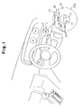
- Fig. 1 is a schematic diagram showing the engine switch device 1.
- the engine switch device 1 (hereafter simply referred to as switch device 1) is arranged in front of the driver's seat in the vehicle.
- the engine switch device 1 includes a key cylinder 10 and a push button switch 30.
- the push button switch 30 has an annular push button 31.
- the key cylinder 10 has a key slot 11, which is arranged in the center of the push button 31. In other words, the push button 31 surrounds the key slot 11.
- Fig. 2 is a schematic block diagram of the vehicle, a mechanical key 40, and a portable device 50.
- the user carries the mechanical key 40 and the portable device 50.
- Devices such as a transceiver 60, an immobilizer electronic control unit (ECU) 35, a power supply ECU 2, an engine controller 4, and a steering lock device 3, are installed in the vehicle.
- ECU immobilizer electronic control unit
- the key cylinder 10 has a structure similar to that of a normal key cylinder.
- the key cylinder 10 includes a rotor case 13 and a rotor 14, which is arranged in the rotor case 13.
- the rotor 14 includes the key slot 11, which receives the mechanical key 40. Further, the rotor 14 includes a plurality of tumblers 15.
- the tumblers 15 are all engaged with a key groove of the mechanical key 40. In this state, the ends of every tumbler 15 is retracted inward from the outer surface of the rotor 14. This enables the rotor 14 to be rotated.
- a projection 19 extends from the distal end of the rotor 14 towards the end wall of the rotor case 13. The rotation of the rotor 14 moves the projection 19 along an arcuate path.
- a circuit board 18 is arranged on the end wall of the rotor case 13. An electric signal is provided to the power supply ECU 2 from the circuit board 18.
- the circuit board 18 includes five contacts 18a, which are arranged in correspondence with the moving path of the projection 19 to contact the projection 19.
- the contacts 18a are separated from each other by predetermined intervals.
- the five contacts 18a correspond to operation states represented by "LOCK”, "OFF”, “ACC”, "IG-ON”, and "START".
- the steering wheel In the “OFF” state, the steering wheel is unlocked but power is not supplied to the vehicle. In the “ACC” state, power is supplied to accessories. In the “IG-ON” state, power is supplied to every device installed in the vehicle in addition to the accessories. In the “START” state, the engine is started.
- the push button switch 30 includes a push button 31 and a switch 33.
- a hole 31a extends through the center of the push button 31.
- the key slot 11 of the key cylinder 10 is arranged in the hole 31a.
- the push button 31 moves separately from the key cylinder 10 between a push position and a release position.
- the push button 31 includes a push surface 31b, which is flush with the surface of the key slot 11.
- the characters of START/STOP is marked on the push surface 31b so that the user can easily recognize the switch device 1.
- characters 36 indicating different operation states, such as "LOCK”, “OFF”, “ACC”, “IG-ON”, and "START” are marked on the push surface 31b (refer to Fig. 1). Accordingly, the user can easily recognize the operating states selectable by the mechanical key 40.
- An extension 32 extends from the surface of the push button 31 on the opposite side of the push surface 31b.
- a guide (not shown), which extends in the axial direction of the rotor 14, guides the extension 32. The guide restricts lateral movement of the extension 32 and prevents the push button 31 from rotating about the rotor 14.
- a spring 16 is arranged between the push button 31 and the rotor case 13. The spring 16 urges the push button 31 in a direction opposite to the direction in which the user pushes the push button 31.
- the switch 33 is located at a position corresponding to the extension 32.
- the switch 33 is a self-reset type push button switch. When the vehicle user pushes the push button 31, the push button 31 moves so that the extension 32 pushes the switch 33. This activates the switch 33 and provides the power supply ECU 2 with an ON signal. When the user stops pushing the push button 31, the force of the spring 16 returns the push button 31 to the release position.
- the push button 31 includes an annular primary coil 34 (communicating means).
- the primary coil 34 is electrically connected to the immobilizer ECU 35 (Fig. 2) by a wire, such as a lead line or the like.
- the immobilizer ECU 35 includes a memory 35a, which stores an exclusive identification code.
- the vehicle battery (not shown) functions as the power supply for the immobilizer ECU 35.
- the immobilizer ECU 35 controls the oscillation of the primary coil 34 to intermittently transmit a request signal from the primary coil 34.
- the mechanical key 40 which is inserted in the key slot 11, includes a grip 41.
- a transponder 42 is incorporated in the grip 41.
- the transponder 42 includes a secondary coil 43 and a transponder control circuit 44 (Fig. 2).
- the transponder control circuit 44 includes a memory 44a, which stores an exclusive identification code.
- the transponder control circuit 44 When receiving a request signal from the primary coil 34 of the immobilizer ECU 35 via the secondary coil 43, the transponder control circuit 44 changes its impedance. In accordance with the change in the impedance, the oscillation state of the primary coil 34 changes. Based on the change in the oscillation state of the primary coil 34, the immobilizer ECU 35 reads an identification code of the mechanical key 40. The immobilizer ECU 35 compares the identification code of the transponder 42 with the identification code stored in the memory 35a. When the two identification codes match, the immobilizer ECU 35 provides the power supply ECU 2 with an immobilizer verification signal and provides the steering lock device 3 with an unlock signal.
- the immobilizer ECU 35 does not provide the power supply ECU 2 with the verification signal to disable the starting of the engine.
- the portable device 50 carried by the user includes a microcomputer 51, a receiver circuit 52, and a transmitter circuit 53.
- the receiver circuit 52 includes an antenna 52a.
- the transmitter circuit 53 includes an antenna 53a.
- the microcomputer 51 includes a memory 51a, which stores an identification code.
- the receiver circuit 52 receives a request signal from the vehicle via the antenna 52a and provides the request signal to the microcomputer 51.
- the microcomputer 51 reads the identification code from the memory 51a and provides the transmitter circuit 53 with an identification code signal.
- the transmitter circuit 53 transmits an identification code signal via the antenna 53a.
- the transceiver 60 installed in the vehicle includes a smart ECU 61, a transmitter circuit 62, and a receiver circuit 63.
- the smart ECU 61 includes a memory 61a, which stores an identification code exclusive to the vehicle.
- the transmitter circuit 62 includes an antenna 62a.
- the receiver circuit 63 includes an antenna 63a.
- the smart ECU 61 intermittently provides the transmitter circuit 62 with a request signal.
- the transmitter circuit 62 transmits the request signal within a range near the vehicle via the antenna 62a.
- the receiver circuit 63 receives the identification code signal transmitted from the portable device 50 via the antenna 63a and provides the smart ECU 61 with the identification code signal.
- the smart ECU 61 compares the identification code included in the identification code signal from the portable device 50 with the identification code stored in the memory 61a. When the two identification codes match, the smart ECU 61 provides the power supply ECU 2 with a smart ignition verification signal and provides the steering lock device 3 with an unlock signal. In response to the unlock signal, the steering lock device 3 unlocks the steering wheel.
- the power supply ECU 2 installed in the vehicle is connected to the smart ECU 61, the immobilizer ECU 35, the engine controller 4, and the switch 33 of the push button switch 30.
- the vehicle battery functions as the power source of the power supply ECU 2.
- the power supply ECU 2 provides the engine controller 4 with a start signal in response to an ON signal from the switch 33.
- the immobilizer ECU 35 provides the power supply ECU 2 with the immobilizer verification signal and the contact 18a of the circuit board 18 is switched to "START”
- the power supply ECU 2 provides the engine controller 4 with the start signal. Then, the engine controller 4 starts the engine in accordance with the start signal.
- the power supply ECU 2 provides the engine controller 4 with a stop signal. Further, the turning of the mechanical key 40 from the "IG-ON" position to the "ACC” position provides the engine controller 4 with the stop signal.
- the engine controller 4 stops the engine in accordance with the stop signal.
- the switch device 1, the portable device 50, the transceiver 60 and the power supply ECU 2 configure a smart ignition device.
- the user who is carrying the portable device 50, enters the vehicle.
- the identification code of the smart ECU 61 in the transceiver 60 and the identification code of the microcomputer 51 in the portable device 51 are compared with each other.
- the smart ECU 61 provides the steering lock device 3 with the unlock signal and provides the power supply ECU 2 with a smart ignition verification signal.
- the steering lock device 3 unlocks the steering wheel.
- the user pushes the push button 31 of the push button switch 30.
- the extension 32 activates the switch 33.
- the switch 33 provides the power supply ECU 2 with an ON signal.
- the power supply ECU 2 provides the engine controller 4 with a start signal in response to the ON signal.
- the engine controller 4 starts the engine in accordance with the start signal.
- the power supply ECU 2 provides the engine controller 4 with a stop signal.
- the engine controller 4 stops the engine in response to the stop signal.
- the user inserts the mechanical key 40 in the key slot 11 of the key cylinder 10.
- the identification code of the transponder 42 and the identification code of the immobilizer ECU 35 are compared with each other.
- the immobilizer ECU 35 provides the steering lock device 3 with the unlock signal and provides the power supply ECU 2 with the immobilizer verification signal.
- the steering lock device 3 unlocks the steering wheel.
- the mechanical key 40 is located at the LOCK position when the user first inserts the mechanical key 40 in the key slot 11. As the user turns the mechanical key 40 from the "LOCK” position to the “OFF” position, the projection 19 moves to the OFF contact 18a of the circuit board 18. As a result, the circuit board 18 provides the power supply ECU 2 with an OFF signal. In the "OFF" state, the power supply ECU 2 keeps the engine stopped.
- the circuit board 18 provides the power supply ECU 2 with an ACC signal.
- the power supply ECU 2 determines the type of signal the immobilizer ECU 35 is providing.
- the power supply ECU 2 activates an ACC relay (not shown).
- the ACC relay is arranged along a power supply line that electrically connects the battery and the accessories. Accordingly, the activation of the ACC relay supplies the accessories with power from the battery.
- the circuit board 18 provides the power supply ECU 2 with an IG-ON signal.
- the power supply ECU 2 activates a plug relay (not shown). This enables the engine to be started.
- the power supply ECU 2 provides the engine controller 4 with a start signal.
- the engine controller 4 starts the engine in response to the start signal.
- the user turns the mechanical key 40 from the "IG-ON" position to the "ACC" position.
- the power supply ECU 2 provides the engine controller 4 with a stop signal.
- the engine controller 4 stops the engine in accordance with the stop signal.
- the switch device 1 of the first embodiment has the advantages described below.
- a switch device 1 according to a second embodiment of the present invention will now be described with reference to Figs. 4, 5A, and 5B.
- Fig. 4 is a schematic view showing the switch device 1 of the second embodiment.
- the rotor 22 is rotatable when the mechanical key 40 is inserted in the key slot 11.
- the key cylinder 20 is configured to enable the rotor 22 to be pushed after the rotor 22 is rotated. The pushing of the rotor 22 starts the engine.
- the key cylinder 20 includes a rotor 22 and a rotor case 21, which accommodates the rotor 22.
- a flange 27 extends from the rotor 22 near the key slot 11.
- a tab 23 extends from the outer surface of the rotor 22.
- a guide groove 24, which receives the tab 23, extends along the inner surface of the rotor case 21.
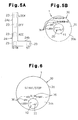
- Fig. 5A is a deployment diagram showing the guide groove 24.
- the guide groove 24 includes a arcuate first guide groove 24a, which extends in the circumferential direction of the rotor case 21, and a linear second guide groove 24b, which extends in the axial direction of the rotor 22 from one end of the first guide groove 24a.
- the axial length of the second guide groove 24b is slightly greater than the distance between the extension 32 and the switch 33. Accordingly, when the rotor 22 is pushed, the extension 32 of the push button 31 pushes the switch 33 before the tab 23 reaches the end of the second guide groove 24b. In the same manner as in the first embodiment, the push button 31 incorporates the primary coil 34.
- a circuit board 25 is arranged in the rotor case 21 at a position that is slightly closer to the end face from the middle portion.
- the circuit board 25 includes four contacts 25a, which come into contact with the projection 19 and which are arranged in correspondence with the moving path of the projection 19.
- the four contacts 25a correspond to operation states represented by "LOCK”, "OFF”, “ACC”, and "IG-ON”.
- a spring 26 is arranged between the circuit board 25 and the end face of the rotor case 21. The spring 26 urges the circuit board 25 toward the rotor 22.
- the guide groove 24 guides the tab 23, which rotates with the rotor 22 to the "LOCK”, “OFF”, “ACC”, and “IG-ON (PUSH ST)" positions.
- the rotor 22 is movable from the “LOCK” position to the "IG-ON” position with the first guide groove 24a guiding the tab 23 when the mechanical key 40 is inserted in the key slot 11.
- the second guide groove 24b guides the tab 23 to an "ST” position. This moves the push button 31 with the rotor 22.
- the extension 32 of the push button 31 activates the switch 33.
- the switch 33 provides the power supply ECU 2 with an ON signal.
- the push button 31 of the push button switch 30 includes a stepped portion 37, which functions as a stopper, extending inward from the wall of the hole 31a.
- the spring 16 urges the push button 31 so that the stepped portion 37 contacts the flange 27.
- the rotor 22 is rotated with the flange 27 in contact with the stepped portion 37.
- the push button 31 moves together with the rotor 22.
- the push button 31 moves independently from the rotor 22.
- the characters 36 marked on the push button 31 in correspondence with the selectable operation states differ from the characters 36 of the first embodiment.
- the characters 36 of "LOCK”, “OFF”, “ACC”, and "IG-ON (PUSH-ST)" are marked on the push surface 31b.
- a guide (not shown) extending in the axial direction of the rotor 22 guides the extension 32 so that the push button 31 does not rotate about the rotor 22.
- the starting of the engine with the push button switch 30 is performed in the same manner as in the first embodiment and will thus not be described.
- the starting of the engine with the key cylinder 20 will now be described.
- the identification code of the transponder 42 and the identification code of the immobilizer ECU 35 are compared with each other.
- the immobilizer ECU 35 provides the steering lock device 3 with an unlock signal and provides the power supply ECU 2 with the immobilizer verification signal.
- the steering lock device 3 unlocks the steering wheel in accordance with the unlock signal.
- the tab 23 is located at the "LOCK" position as shown by the broken lines in Fig. 5A.
- the first guide groove 24a guides the tab 23 to the "ACC" position as shown by the broken lines of Fig. 5A. Simultaneously, the projection 19 of the rotor 22 moves to the ACC contact 25a of the circuit board 25.
- the first guide groove 24a guides the tab 23 to the "IG-ON” position as shown by the broken lines of Fig. 5A. Simultaneously, the projection 19 of the rotor 22 moves to the IG-ON contact 25a of the circuit board 25.
- the user pushes the mechanical key 40 with the rotor 22.
- the second guide groove 24b guides the tab 23 to the "ST" position as shown by the broken lines of Fig. 5A.
- the switch 33 provides the power supply ECU 2 with the ON signal.
- the power supply ECU 2 provides the engine controller 4 with a start signal. The engine controller 4 then starts the engine in accordance with the start signal.
- the power supply ECU 2 provides the engine controller 4 with a stop signal.
- the engine controller 4 then stops the engine in accordance with the stop signal.
- the switch device 1 of the second embodiment has the advantage described below.
- the rotor 22 is movable in its axial direction. The pushing of the rotor 22 pushes the switch 33 of the push button switch 30 and starts the engine. In this structure, a START contact for starting the engine does not have to be formed on the circuit board 25 of the key cylinder 20. This saves costs.
- the key slots 11 of the key cylinders 10 and 20 are arranged in the center of the push button 31 of the push button switch 30.
- the key slot 11 may be located at a position separated from the center of the push button 31, as shown in Fig. 6.
- the area of the push surface 31b increases.
- the switch device 1 be provided with a guide rod for guiding the movement of the push button 31.
- the switch device 1 may be configured so that the entire key cylinder moves with the push button 31 of the push button switch 30 when the push button 31 is pushed. This may be achieved by using, for example, an additional coil spring and an additional switch. In such a case, the additional coil spring urges the rotor case 13. The additional switch is arranged to come into contact with the rotor case 13 when the rotor case 13 moves. In this structure, the user pushes the key cylinder with the mechanical key 40 inserted in the key slot 11. This moves the key cylinder so that the rotor case 13 pushes the additional switch.
- the second guide groove 24b is located in correspondence with the "IG-ON" position.
- a groove similar to the second guide groove 24b may be formed at a position corresponding to, for example, the "LOCK” position or the "OFF" position.
- the push surface 31b of the push button 31 is flush with the end face of the rotor 14 or 22.
- the push surface 31b may project from the end face of the rotor 14 or 22. This enables the user to push the push button 31 with further ease.
- the switch 33 be arranged so that when the push button 31 is pushed, the switch 33 is activated before the push surface 31b becomes flush with the end face of the rotor 14 or 22.
- the edge of the wall defining the hole 31a of the push button 31 may be tapered. This prevents the grip 41 from interfering with the push button 31 when the user inserts the mechanical key 40 into the key slot 11.
- the switch 33 of the push button switch 30 does not have to be a self-reset type push button switch.
- a switch including a pair of electrodes may be employed.
- the two electrodes are respectively arranged in the opposing surfaces of the push button 31 and the rotor case 13. When the push button 31 is pushed, the two electrodes come into contact with each other. The contact between the two electrodes starts the engine.
- the push button switch 30 may include other known switches.
- the smart ignition function enables the starting of the engine, and the push button 31 is pushed to start the engine.
- the engine may be started by pushing the push button 31 when the identification code of the mechanical key 40 matches the identification code of the memory 35a in the immobilizer ECU 35.
- the switch device 1 of the first embodiment includes the key cylinder 10, which starts the engine by rotating the rotor 14.
- the switch device 1 of the second embodiment includes the key cylinder 20, which starts the engine by pushing the rotor 22.
- any type of key cylinder may be employed in the switch device 1 as long as the push button is located near the key cylinder.
- the communicating means of the push button 31 is not limited to the primary coil 34 used in relation with the immobilizer function.
- the communicating means may have any structure as long as the communicating means is used for identification code comparison.
- the push button 31 is annular.
- the push button 31 may have a polygonal shape, such as a square shape. Nevertheless, it is preferred that the antenna used in relation with the immobilizer function be annular.
- the key cylinders 10 and 20 include the tumblers 15 to enable the rotation of the rotors 14 and 22 when the key groove of the mechanical key 40 properly engages the tumblers 15.
- the key cylinders 10 and 20 do not necessarily have to have the tumblers 15 since the identification codes are compared through the immobilizer function when the mechanical key 40 is inserted in the key slot 11.
- a pin may be used to keep the mechanical key 40 held in the key slot 11 when the engine is running.
- a wire such as a lead line, or the like, connects the primary coil 34 and the immobilizer ECU 35.
- the spring 16 that urges the push button 31 may be used as part of the wire. In such a case, it is preferred that a spring made of material having low electric resistance be used.
- the switch 33 is used by the key cylinder 20 and the push button switch 30.
- a further switch may be provided exclusively for the key cylinder 20. In such a case, the pushing of the rotor 22 pushes the further switch.
- the switch device 1 is configured so that the push button 31 moves together with the rotor 22 when the rotor 22 is pushed.
- the switch device 1 may be configured so that the push button 31 does not move when the rotor 22 is pushed. In this structure, an additional switch that is pushed when the rotor 22 is pushed is necessary.
Landscapes
- Engineering & Computer Science (AREA)
- Mechanical Engineering (AREA)
- Lock And Its Accessories (AREA)
- Push-Button Switches (AREA)
- Switches With Compound Operations (AREA)
Applications Claiming Priority (2)
| Application Number | Priority Date | Filing Date | Title |
|---|---|---|---|
| JP2003030015A JP4137657B2 (ja) | 2003-02-06 | 2003-02-06 | エンジン始動・停止用スイッチ装置 |
| JP2003030015 | 2003-02-06 |
Publications (3)
| Publication Number | Publication Date |
|---|---|
| EP1445158A2 true EP1445158A2 (de) | 2004-08-11 |
| EP1445158A3 EP1445158A3 (de) | 2005-02-09 |
| EP1445158B1 EP1445158B1 (de) | 2009-01-14 |
Family
ID=32653000
Family Applications (1)
| Application Number | Title | Priority Date | Filing Date |
|---|---|---|---|
| EP20040002329 Expired - Fee Related EP1445158B1 (de) | 2003-02-06 | 2004-02-03 | Motor-Anlasserschalter |
Country Status (6)
| Country | Link |
|---|---|
| US (1) | US7290416B2 (de) |
| EP (1) | EP1445158B1 (de) |
| JP (1) | JP4137657B2 (de) |
| KR (1) | KR100943928B1 (de) |
| CN (1) | CN1522905B (de) |
| DE (1) | DE602004018997D1 (de) |
Cited By (4)
| Publication number | Priority date | Publication date | Assignee | Title |
|---|---|---|---|---|
| WO2005100107A1 (de) * | 2004-04-14 | 2005-10-27 | Siemens Aktiengesellschaft | Betätigungsbaugruppe für ein kraftfahrzeug |
| EP1630412A1 (de) * | 2004-08-31 | 2006-03-01 | Nissan Technology Centre Europe Limited | Motorstartsteuervorrichtung und- Verfahren |
| DE102008035125A1 (de) * | 2008-07-28 | 2010-02-04 | Volkswagen Ag | Verfahren zur Herstellung eines Zündschlosses und entsprechendes Zündschloss |
| EP2461015B1 (de) | 2009-07-29 | 2015-07-22 | Kabushiki Kaisha Honda Lock | Schaltvorrichtung zum starten/stoppen eines motors |
Families Citing this family (38)
| Publication number | Priority date | Publication date | Assignee | Title |
|---|---|---|---|---|
| JP2004324573A (ja) * | 2003-04-25 | 2004-11-18 | Tokai Rika Co Ltd | 無接点式エンジン始動スイッチ装置 |
| BRPI0515802A (pt) * | 2005-01-31 | 2008-08-05 | Honda Lock Kk | dispositivo de chave giratória |
| JP4548205B2 (ja) * | 2005-04-27 | 2010-09-22 | 株式会社デンソー | ワイヤレス送受信機及びその製造方法 |
| JP4767593B2 (ja) * | 2005-06-02 | 2011-09-07 | 株式会社ホンダロック | 車両用イグニッションスイッチの操作装置 |
| JP4733450B2 (ja) * | 2005-07-12 | 2011-07-27 | 朝日電装株式会社 | イグニッションスイッチ装置 |
| DE102005043232A1 (de) * | 2005-09-09 | 2007-03-15 | Bayerische Motoren Werke Ag | Vorrichtung zum Starten des Motors eines Kraftfahrzeugs |
| JP2007302216A (ja) * | 2006-05-15 | 2007-11-22 | Tokai Rika Co Ltd | 車両の盗難防止装置 |
| US20070267243A1 (en) * | 2006-05-19 | 2007-11-22 | Textron Inc. | Multi-purpose key switch for lightweight utility vehicle |
| KR100892473B1 (ko) | 2006-10-31 | 2009-04-10 | 현대자동차주식회사 | 자동차용 스마트키 시동장치 |
| CA2571594A1 (en) * | 2006-12-15 | 2008-06-15 | Fortin Auto Radio Inc. | Interface emulating the starting of a vehicle having an electronic starting system |
| US7968811B2 (en) * | 2007-06-29 | 2011-06-28 | Harley-Davidson Motor Company Group, Inc. | Integrated ignition and key switch |
| DE102008032585B4 (de) * | 2008-07-11 | 2018-07-19 | Huf Hülsbeck & Fürst Gmbh & Co. Kg | Vorrichtung zur Ansteuerung eines Sperrgliedes |
| DE102008035126A1 (de) * | 2008-07-28 | 2010-02-04 | Marquardt Gmbh | Verfahren zum Betreiben eines Fahrzeugs und entsprechendes Zündschloss |
| DE102008035243B4 (de) * | 2008-07-29 | 2016-12-22 | Continental Automotive Gmbh | Schalteinrichtung für ein Fahrzeug mit einer elektronischen Wegfahrsperre und Verfahren zur Betätigung einer elektronischen Wegfahrsperre |
| KR20100026162A (ko) * | 2008-08-29 | 2010-03-10 | 현대자동차주식회사 | 버튼 시동 시스템을 구비한 차량의 비상 시동 장치 |
| US8542092B2 (en) * | 2009-01-29 | 2013-09-24 | Trw Automotive U.S. Llc | Keyless-go ignition switch with fault backup |
| US20110018684A1 (en) * | 2009-07-23 | 2011-01-27 | Wayne Hua Wang | Remote keyless ignition system and method |
| CN102001323B (zh) * | 2009-09-01 | 2013-02-20 | 上海科林艾汽车配件有限公司 | 复合式双推开关运行方法及其装置 |
| US9467009B2 (en) * | 2009-12-22 | 2016-10-11 | Kress Motors, LLC | Dipolar transverse flux electric machine |
| US8593011B2 (en) * | 2010-05-17 | 2013-11-26 | Chrysler Group Llc | Rotary push-button ignition switch |
| JP5502975B2 (ja) * | 2012-12-05 | 2014-05-28 | 株式会社ホンダロック | エンジンのスタート・ストップスイッチ装置 |
| CN104425173A (zh) * | 2013-09-09 | 2015-03-18 | 天津视觉天堂影像文化传媒有限责任公司 | 电器开关锁 |
| JP6074812B2 (ja) * | 2013-12-13 | 2017-02-08 | 株式会社ホンダロック | シリンダ錠装置 |
| JP6176733B2 (ja) * | 2014-05-23 | 2017-08-09 | アルプス電気株式会社 | エンジンスタートスイッチ |
| CN103996561A (zh) * | 2014-06-09 | 2014-08-20 | 王勇 | 一种机动车点火开关和机动车及机动车启动方法 |
| US10443267B2 (en) * | 2015-05-04 | 2019-10-15 | Spectrum Brands, Inc. | Lockset with cylinder integrity sensor |
| KR102166706B1 (ko) * | 2015-06-10 | 2020-10-19 | 현대자동차주식회사 | 버튼 타입 전자식 변속시스템 |
| JP6413966B2 (ja) * | 2015-07-24 | 2018-10-31 | スズキ株式会社 | キーレスエントリーシステムを有する船外機のスイッチ装置 |
| US10448628B2 (en) * | 2017-03-27 | 2019-10-22 | Cnh Industrial America Llc | Electronic start system for an agricultural machine |
| CN108082071B (zh) * | 2017-12-24 | 2020-09-08 | 瑞安市虹宇科技有限公司 | 一种具有阻尼的汽车启动点火方法 |
| CN108116338B (zh) * | 2017-12-24 | 2020-05-19 | 林权豪 | 一种基于磁力回弹式的锁栓锁筒结构的汽车点火装置 |
| CN108116337B (zh) * | 2017-12-24 | 2020-04-28 | 林权豪 | 一种基于弹力线拉力的锁栓锁筒结构的汽车点火装置 |
| CN108116336B (zh) * | 2017-12-24 | 2020-05-05 | 林权豪 | 一种基于空气压力的锁栓锁筒结构的汽车点火装置 |
| CN108167103B (zh) * | 2017-12-24 | 2020-05-19 | 林权豪 | 一种基于弹簧弹力的锁栓锁筒结构的汽车点火装置 |
| CN109080584B (zh) * | 2018-07-18 | 2020-02-21 | 吉利汽车研究院(宁波)有限公司 | 一种车辆启动控制装置及一种车辆 |
| JP7127494B2 (ja) * | 2018-11-05 | 2022-08-30 | 株式会社デンソー | 電池監視装置 |
| JP7303140B2 (ja) * | 2020-03-12 | 2023-07-04 | 株式会社東海理化電機製作所 | スイッチ装置 |
| JP2021144865A (ja) * | 2020-03-12 | 2021-09-24 | 株式会社東海理化電機製作所 | スイッチ装置 |
Citations (1)
| Publication number | Priority date | Publication date | Assignee | Title |
|---|---|---|---|---|
| JP2002295089A (ja) | 2001-03-29 | 2002-10-09 | Tokai Rika Co Ltd | キーシリンダを備えたエンジン始動許可機構 |
Family Cites Families (18)
| Publication number | Priority date | Publication date | Assignee | Title |
|---|---|---|---|---|
| US1748255A (en) * | 1926-12-11 | 1930-02-25 | Packard Motor Car Co | Lock |
| US2060951A (en) * | 1934-06-19 | 1936-11-17 | Allen Rae & Company Ltd | Key-operated electric switch, particularly for use on motor vehicles |
| US3522394A (en) * | 1969-01-24 | 1970-07-28 | Donald W Bellrose | Combined automobile ignition and light switch |
| US3794796A (en) * | 1971-04-26 | 1974-02-26 | A Dwan | Alcohol security interlock switch device |
| US4154992A (en) * | 1977-06-09 | 1979-05-15 | Aspman Harry C | Ignition key and headlight switch engaging device |
| US4956983A (en) * | 1988-09-22 | 1990-09-18 | Kabushiki Kaisha Tokai Rika Denki Seisakusho | Locking apparatus with a key |
| GB2290342B (en) * | 1994-06-03 | 1998-04-22 | Strattec Security Corp | Tumblerless automobile ignition lock |
| JP3580923B2 (ja) * | 1995-12-21 | 2004-10-27 | 株式会社日本自動車部品総合研究所 | 盗難防止装置 |
| US5799520A (en) * | 1996-03-07 | 1998-09-01 | The Eastern Company | Combined lock and linear actuator |
| JP3587409B2 (ja) * | 1996-03-26 | 2004-11-10 | 本田技研工業株式会社 | 車両の盗難検出機構及び盗難防止装置 |
| DE19939733C2 (de) * | 1999-08-21 | 2001-10-11 | Huf Huelsbeck & Fuerst Gmbh | Vorrichtung zum Starten eines Fahrzeugmotors mittels eines elektronischen Schlüssels |
| DE19943999C2 (de) * | 1999-09-14 | 2001-09-20 | Daimler Chrysler Ag | Elektronisches Zündschloss |
| JP3372228B2 (ja) * | 1999-09-29 | 2003-01-27 | 本田技研工業株式会社 | 車両用電子キー装置 |
| JP2001351453A (ja) * | 2000-06-09 | 2001-12-21 | Tokai Rika Co Ltd | 押しボタンスイッチ |
| DE10034348A1 (de) * | 2000-07-14 | 2002-01-24 | Daimler Chrysler Ag | System zur Inbetriebnahme eines motorangetriebenen Kraftfahrzeugs |
| FR2817214B1 (fr) * | 2000-11-29 | 2003-03-28 | Valeo Securite Habitacle | Dispositif de commande et antivol pour vehicule automobile comprenant ce dispositif de commande |
| JP3781644B2 (ja) * | 2001-07-19 | 2006-05-31 | 株式会社ユーシン | ステアリングロック装置 |
| JP2003291778A (ja) | 2002-04-04 | 2003-10-15 | Tokai Rika Co Ltd | スマートイグニッション装置の操作機構 |
-
2003
- 2003-02-06 JP JP2003030015A patent/JP4137657B2/ja not_active Expired - Fee Related
-
2004
- 2004-02-03 EP EP20040002329 patent/EP1445158B1/de not_active Expired - Fee Related
- 2004-02-03 DE DE200460018997 patent/DE602004018997D1/de not_active Expired - Lifetime
- 2004-02-04 US US10/771,978 patent/US7290416B2/en not_active Expired - Fee Related
- 2004-02-04 CN CN2004100037318A patent/CN1522905B/zh not_active Expired - Fee Related
- 2004-02-05 KR KR1020040007625A patent/KR100943928B1/ko not_active IP Right Cessation
Patent Citations (1)
| Publication number | Priority date | Publication date | Assignee | Title |
|---|---|---|---|---|
| JP2002295089A (ja) | 2001-03-29 | 2002-10-09 | Tokai Rika Co Ltd | キーシリンダを備えたエンジン始動許可機構 |
Cited By (6)
| Publication number | Priority date | Publication date | Assignee | Title |
|---|---|---|---|---|
| WO2005100107A1 (de) * | 2004-04-14 | 2005-10-27 | Siemens Aktiengesellschaft | Betätigungsbaugruppe für ein kraftfahrzeug |
| EP1630412A1 (de) * | 2004-08-31 | 2006-03-01 | Nissan Technology Centre Europe Limited | Motorstartsteuervorrichtung und- Verfahren |
| DE102008035125A1 (de) * | 2008-07-28 | 2010-02-04 | Volkswagen Ag | Verfahren zur Herstellung eines Zündschlosses und entsprechendes Zündschloss |
| DE102008035125B4 (de) * | 2008-07-28 | 2019-09-05 | Volkswagen Ag | Verfahren zur Herstellung eines Zündschlosses und entsprechendes Zündschloss |
| EP2461015B1 (de) | 2009-07-29 | 2015-07-22 | Kabushiki Kaisha Honda Lock | Schaltvorrichtung zum starten/stoppen eines motors |
| EP2461015B2 (de) † | 2009-07-29 | 2018-11-07 | Kabushiki Kaisha Honda Lock | Schaltvorrichtung zum starten/stoppen eines motors |
Also Published As
| Publication number | Publication date |
|---|---|
| KR100943928B1 (ko) | 2010-02-24 |
| CN1522905B (zh) | 2010-04-28 |
| CN1522905A (zh) | 2004-08-25 |
| US7290416B2 (en) | 2007-11-06 |
| KR20040071648A (ko) | 2004-08-12 |
| US20040155525A1 (en) | 2004-08-12 |
| EP1445158B1 (de) | 2009-01-14 |
| EP1445158A3 (de) | 2005-02-09 |
| JP4137657B2 (ja) | 2008-08-20 |
| JP2004237887A (ja) | 2004-08-26 |
| DE602004018997D1 (de) | 2009-03-05 |
Similar Documents
| Publication | Publication Date | Title |
|---|---|---|
| US7290416B2 (en) | Engine switch device | |
| US4965460A (en) | Anti-theft system for a vehicle | |
| JP3142508B2 (ja) | 車両電子キー装置 | |
| EP1574385B1 (de) | Passives Zugangsystem | |
| EP1469428B1 (de) | Schalteinrichtung, insbesondere Zündschalter, mit Transponderabfrageeinrichtung über Radiowellen | |
| US8237542B2 (en) | Key system | |
| US6661114B2 (en) | Shift apparatus for vehicles | |
| KR20090046121A (ko) | 차량용 시동버튼장치 | |
| US8022879B2 (en) | Antenna structure for wireless communication device | |
| EP1384844A2 (de) | Fahrzeugtürgriff | |
| US6794988B1 (en) | Control device for a motor vehicle | |
| JP4685892B2 (ja) | エンジン始動・停止用スイッチ装置 | |
| JP2007277924A (ja) | キー装置 | |
| JP2001130381A (ja) | 車両用電子キー装置 | |
| JP4689875B2 (ja) | シフト装置 | |
| JP2009121279A (ja) | エンジン始動停止スイッチ装置 | |
| JP4355068B2 (ja) | 車両用電子キー装置 | |
| JP2005248902A (ja) | スロット型キー装置のキーインターロック回路 | |
| JP2007277927A (ja) | キー装置 | |
| JP3808556B2 (ja) | キーシリンダ | |
| JP2006298194A (ja) | エンジン始動装置及びエンジン始動システム | |
| KR20170051621A (ko) | 차량 이모빌라이저 장치 | |
| JP2007038862A (ja) | ステアリングロック装置、ステアリングロック方法 | |
| JP2017007585A (ja) | エンジン始動装置 | |
| JPH0949352A (ja) | キー装置 |
Legal Events
| Date | Code | Title | Description |
|---|---|---|---|
| PUAI | Public reference made under article 153(3) epc to a published international application that has entered the european phase |
Free format text: ORIGINAL CODE: 0009012 |
|
| AK | Designated contracting states |
Kind code of ref document: A2 Designated state(s): AT BE BG CH CY CZ DE DK EE ES FI FR GB GR HU IE IT LI LU MC NL PT RO SE SI SK TR |
|
| AX | Request for extension of the european patent |
Extension state: AL LT LV MK |
|
| PUAL | Search report despatched |
Free format text: ORIGINAL CODE: 0009013 |
|
| AK | Designated contracting states |
Kind code of ref document: A3 Designated state(s): AT BE BG CH CY CZ DE DK EE ES FI FR GB GR HU IE IT LI LU MC NL PT RO SE SI SK TR |
|
| AX | Request for extension of the european patent |
Extension state: AL LT LV MK |
|
| 17P | Request for examination filed |
Effective date: 20050330 |
|
| AKX | Designation fees paid |
Designated state(s): DE FR GB |
|
| 17Q | First examination report despatched |
Effective date: 20080212 |
|
| GRAP | Despatch of communication of intention to grant a patent |
Free format text: ORIGINAL CODE: EPIDOSNIGR1 |
|
| GRAS | Grant fee paid |
Free format text: ORIGINAL CODE: EPIDOSNIGR3 |
|
| GRAA | (expected) grant |
Free format text: ORIGINAL CODE: 0009210 |
|
| AK | Designated contracting states |
Kind code of ref document: B1 Designated state(s): DE FR GB |
|
| REG | Reference to a national code |
Ref country code: GB Ref legal event code: FG4D |
|
| REF | Corresponds to: |
Ref document number: 602004018997 Country of ref document: DE Date of ref document: 20090305 Kind code of ref document: P |
|
| PLBE | No opposition filed within time limit |
Free format text: ORIGINAL CODE: 0009261 |
|
| STAA | Information on the status of an ep patent application or granted ep patent |
Free format text: STATUS: NO OPPOSITION FILED WITHIN TIME LIMIT |
|
| 26N | No opposition filed |
Effective date: 20091015 |
|
| PGFP | Annual fee paid to national office [announced via postgrant information from national office to epo] |
Ref country code: FR Payment date: 20120221 Year of fee payment: 9 |
|
| PGFP | Annual fee paid to national office [announced via postgrant information from national office to epo] |
Ref country code: DE Payment date: 20120131 Year of fee payment: 9 |
|
| PGFP | Annual fee paid to national office [announced via postgrant information from national office to epo] |
Ref country code: GB Payment date: 20120201 Year of fee payment: 9 |
|
| GBPC | Gb: european patent ceased through non-payment of renewal fee |
Effective date: 20130203 |
|
| REG | Reference to a national code |
Ref country code: FR Ref legal event code: ST Effective date: 20131031 |
|
| REG | Reference to a national code |
Ref country code: DE Ref legal event code: R119 Ref document number: 602004018997 Country of ref document: DE Effective date: 20130903 |
|
| PG25 | Lapsed in a contracting state [announced via postgrant information from national office to epo] |
Ref country code: GB Free format text: LAPSE BECAUSE OF NON-PAYMENT OF DUE FEES Effective date: 20130203 Ref country code: FR Free format text: LAPSE BECAUSE OF NON-PAYMENT OF DUE FEES Effective date: 20130228 Ref country code: DE Free format text: LAPSE BECAUSE OF NON-PAYMENT OF DUE FEES Effective date: 20130903 |