EP1439655A2 - Optisches Übertragungssystem und optischer Verstärker - Google Patents
Optisches Übertragungssystem und optischer Verstärker Download PDFInfo
- Publication number
- EP1439655A2 EP1439655A2 EP04009662A EP04009662A EP1439655A2 EP 1439655 A2 EP1439655 A2 EP 1439655A2 EP 04009662 A EP04009662 A EP 04009662A EP 04009662 A EP04009662 A EP 04009662A EP 1439655 A2 EP1439655 A2 EP 1439655A2
- Authority
- EP
- European Patent Office
- Prior art keywords
- optical
- light
- signal light
- wdm signal
- amplifier
- Prior art date
- Legal status (The legal status is an assumption and is not a legal conclusion. Google has not performed a legal analysis and makes no representation as to the accuracy of the status listed.)
- Withdrawn
Links
Images


Classifications
-
- H—ELECTRICITY
- H04—ELECTRIC COMMUNICATION TECHNIQUE
- H04B—TRANSMISSION
- H04B10/00—Transmission systems employing electromagnetic waves other than radio-waves, e.g. infrared, visible or ultraviolet light, or employing corpuscular radiation, e.g. quantum communication
- H04B10/25—Arrangements specific to fibre transmission
- H04B10/2581—Multimode transmission
-
- H—ELECTRICITY
- H04—ELECTRIC COMMUNICATION TECHNIQUE
- H04B—TRANSMISSION
- H04B10/00—Transmission systems employing electromagnetic waves other than radio-waves, e.g. infrared, visible or ultraviolet light, or employing corpuscular radiation, e.g. quantum communication
- H04B10/29—Repeaters
- H04B10/291—Repeaters in which processing or amplification is carried out without conversion of the main signal from optical form
- H04B10/293—Signal power control
- H04B10/294—Signal power control in a multiwavelength system, e.g. gain equalisation
- H04B10/296—Transient power control, e.g. due to channel add/drop or rapid fluctuations in the input power
-
- H—ELECTRICITY
- H01—ELECTRIC ELEMENTS
- H01S—DEVICES USING THE PROCESS OF LIGHT AMPLIFICATION BY STIMULATED EMISSION OF RADIATION [LASER] TO AMPLIFY OR GENERATE LIGHT; DEVICES USING STIMULATED EMISSION OF ELECTROMAGNETIC RADIATION IN WAVE RANGES OTHER THAN OPTICAL
- H01S3/00—Lasers, i.e. devices using stimulated emission of electromagnetic radiation in the infrared, visible or ultraviolet wave range
- H01S3/10—Controlling the intensity, frequency, phase, polarisation or direction of the emitted radiation, e.g. switching, gating, modulating or demodulating
- H01S3/13—Stabilisation of laser output parameters, e.g. frequency or amplitude
- H01S3/1301—Stabilisation of laser output parameters, e.g. frequency or amplitude in optical amplifiers
- H01S3/13013—Stabilisation of laser output parameters, e.g. frequency or amplitude in optical amplifiers by controlling the optical pumping
-
- H—ELECTRICITY
- H04—ELECTRIC COMMUNICATION TECHNIQUE
- H04B—TRANSMISSION
- H04B10/00—Transmission systems employing electromagnetic waves other than radio-waves, e.g. infrared, visible or ultraviolet light, or employing corpuscular radiation, e.g. quantum communication
- H04B10/07—Arrangements for monitoring or testing transmission systems; Arrangements for fault measurement of transmission systems
- H04B10/075—Arrangements for monitoring or testing transmission systems; Arrangements for fault measurement of transmission systems using an in-service signal
- H04B10/077—Arrangements for monitoring or testing transmission systems; Arrangements for fault measurement of transmission systems using an in-service signal using a supervisory or additional signal
- H04B10/0771—Fault location on the transmission path
-
- H—ELECTRICITY
- H04—ELECTRIC COMMUNICATION TECHNIQUE
- H04B—TRANSMISSION
- H04B10/00—Transmission systems employing electromagnetic waves other than radio-waves, e.g. infrared, visible or ultraviolet light, or employing corpuscular radiation, e.g. quantum communication
- H04B10/07—Arrangements for monitoring or testing transmission systems; Arrangements for fault measurement of transmission systems
- H04B10/075—Arrangements for monitoring or testing transmission systems; Arrangements for fault measurement of transmission systems using an in-service signal
- H04B10/077—Arrangements for monitoring or testing transmission systems; Arrangements for fault measurement of transmission systems using an in-service signal using a supervisory or additional signal
- H04B10/0775—Performance monitoring and measurement of transmission parameters
-
- H—ELECTRICITY
- H04—ELECTRIC COMMUNICATION TECHNIQUE
- H04B—TRANSMISSION
- H04B10/00—Transmission systems employing electromagnetic waves other than radio-waves, e.g. infrared, visible or ultraviolet light, or employing corpuscular radiation, e.g. quantum communication
- H04B10/07—Arrangements for monitoring or testing transmission systems; Arrangements for fault measurement of transmission systems
- H04B10/075—Arrangements for monitoring or testing transmission systems; Arrangements for fault measurement of transmission systems using an in-service signal
- H04B10/077—Arrangements for monitoring or testing transmission systems; Arrangements for fault measurement of transmission systems using an in-service signal using a supervisory or additional signal
- H04B10/0777—Monitoring line amplifier or line repeater equipment
-
- H—ELECTRICITY
- H04—ELECTRIC COMMUNICATION TECHNIQUE
- H04B—TRANSMISSION
- H04B10/00—Transmission systems employing electromagnetic waves other than radio-waves, e.g. infrared, visible or ultraviolet light, or employing corpuscular radiation, e.g. quantum communication
- H04B10/29—Repeaters
- H04B10/291—Repeaters in which processing or amplification is carried out without conversion of the main signal from optical form
-
- H—ELECTRICITY
- H04—ELECTRIC COMMUNICATION TECHNIQUE
- H04J—MULTIPLEX COMMUNICATION
- H04J14/00—Optical multiplex systems
- H04J14/02—Wavelength-division multiplex systems
- H04J14/0221—Power control, e.g. to keep the total optical power constant
- H04J14/02216—Power control, e.g. to keep the total optical power constant by gain equalization
-
- H—ELECTRICITY
- H04—ELECTRIC COMMUNICATION TECHNIQUE
- H04J—MULTIPLEX COMMUNICATION
- H04J14/00—Optical multiplex systems
- H04J14/02—Wavelength-division multiplex systems
- H04J14/0227—Operation, administration, maintenance or provisioning [OAMP] of WDM networks, e.g. media access, routing or wavelength allocation
- H04J14/0241—Wavelength allocation for communications one-to-one, e.g. unicasting wavelengths
- H04J14/0242—Wavelength allocation for communications one-to-one, e.g. unicasting wavelengths in WDM-PON
- H04J14/0245—Wavelength allocation for communications one-to-one, e.g. unicasting wavelengths in WDM-PON for downstream transmission, e.g. optical line terminal [OLT] to ONU
- H04J14/0246—Wavelength allocation for communications one-to-one, e.g. unicasting wavelengths in WDM-PON for downstream transmission, e.g. optical line terminal [OLT] to ONU using one wavelength per ONU
-
- H—ELECTRICITY
- H01—ELECTRIC ELEMENTS
- H01S—DEVICES USING THE PROCESS OF LIGHT AMPLIFICATION BY STIMULATED EMISSION OF RADIATION [LASER] TO AMPLIFY OR GENERATE LIGHT; DEVICES USING STIMULATED EMISSION OF ELECTROMAGNETIC RADIATION IN WAVE RANGES OTHER THAN OPTICAL
- H01S2301/00—Functional characteristics
- H01S2301/06—Gain non-linearity, distortion; Compensation thereof
-
- H—ELECTRICITY
- H01—ELECTRIC ELEMENTS
- H01S—DEVICES USING THE PROCESS OF LIGHT AMPLIFICATION BY STIMULATED EMISSION OF RADIATION [LASER] TO AMPLIFY OR GENERATE LIGHT; DEVICES USING STIMULATED EMISSION OF ELECTROMAGNETIC RADIATION IN WAVE RANGES OTHER THAN OPTICAL
- H01S3/00—Lasers, i.e. devices using stimulated emission of electromagnetic radiation in the infrared, visible or ultraviolet wave range
- H01S3/05—Construction or shape of optical resonators; Accommodation of active medium therein; Shape of active medium
- H01S3/06—Construction or shape of active medium
- H01S3/063—Waveguide lasers, i.e. whereby the dimensions of the waveguide are of the order of the light wavelength
- H01S3/067—Fibre lasers
- H01S3/06754—Fibre amplifiers
-
- H—ELECTRICITY
- H01—ELECTRIC ELEMENTS
- H01S—DEVICES USING THE PROCESS OF LIGHT AMPLIFICATION BY STIMULATED EMISSION OF RADIATION [LASER] TO AMPLIFY OR GENERATE LIGHT; DEVICES USING STIMULATED EMISSION OF ELECTROMAGNETIC RADIATION IN WAVE RANGES OTHER THAN OPTICAL
- H01S3/00—Lasers, i.e. devices using stimulated emission of electromagnetic radiation in the infrared, visible or ultraviolet wave range
- H01S3/10—Controlling the intensity, frequency, phase, polarisation or direction of the emitted radiation, e.g. switching, gating, modulating or demodulating
- H01S3/10007—Controlling the intensity, frequency, phase, polarisation or direction of the emitted radiation, e.g. switching, gating, modulating or demodulating in optical amplifiers
- H01S3/10015—Controlling the intensity, frequency, phase, polarisation or direction of the emitted radiation, e.g. switching, gating, modulating or demodulating in optical amplifiers by monitoring or controlling, e.g. attenuating, the input signal
-
- H—ELECTRICITY
- H01—ELECTRIC ELEMENTS
- H01S—DEVICES USING THE PROCESS OF LIGHT AMPLIFICATION BY STIMULATED EMISSION OF RADIATION [LASER] TO AMPLIFY OR GENERATE LIGHT; DEVICES USING STIMULATED EMISSION OF ELECTROMAGNETIC RADIATION IN WAVE RANGES OTHER THAN OPTICAL
- H01S3/00—Lasers, i.e. devices using stimulated emission of electromagnetic radiation in the infrared, visible or ultraviolet wave range
- H01S3/10—Controlling the intensity, frequency, phase, polarisation or direction of the emitted radiation, e.g. switching, gating, modulating or demodulating
- H01S3/13—Stabilisation of laser output parameters, e.g. frequency or amplitude
- H01S3/1305—Feedback control systems
-
- H—ELECTRICITY
- H04—ELECTRIC COMMUNICATION TECHNIQUE
- H04B—TRANSMISSION
- H04B2210/00—Indexing scheme relating to optical transmission systems
- H04B2210/07—Monitoring an optical transmission system using a supervisory signal
- H04B2210/075—Monitoring an optical transmission system using a supervisory signal using a pilot tone
-
- H—ELECTRICITY
- H04—ELECTRIC COMMUNICATION TECHNIQUE
- H04B—TRANSMISSION
- H04B2210/00—Indexing scheme relating to optical transmission systems
- H04B2210/07—Monitoring an optical transmission system using a supervisory signal
- H04B2210/078—Monitoring an optical transmission system using a supervisory signal using a separate wavelength
-
- H—ELECTRICITY
- H04—ELECTRIC COMMUNICATION TECHNIQUE
- H04J—MULTIPLEX COMMUNICATION
- H04J14/00—Optical multiplex systems
- H04J14/02—Wavelength-division multiplex systems
- H04J14/0227—Operation, administration, maintenance or provisioning [OAMP] of WDM networks, e.g. media access, routing or wavelength allocation
-
- H—ELECTRICITY
- H04—ELECTRIC COMMUNICATION TECHNIQUE
- H04J—MULTIPLEX COMMUNICATION
- H04J14/00—Optical multiplex systems
- H04J14/02—Wavelength-division multiplex systems
- H04J14/0278—WDM optical network architectures
- H04J14/0279—WDM point-to-point architectures
-
- H—ELECTRICITY
- H04—ELECTRIC COMMUNICATION TECHNIQUE
- H04J—MULTIPLEX COMMUNICATION
- H04J14/00—Optical multiplex systems
- H04J14/02—Wavelength-division multiplex systems
- H04J14/0298—Wavelength-division multiplex systems with sub-carrier multiplexing [SCM]
Definitions
- the present invention relates generally to an optical communication system'and an optical amplifier suitable for long-haul and large-capacity transmission, and more particularly to an optical communication system applicable to WDM (wavelength-division multiplexing) and an optical amplifier suitable for WDM.
- WDM wavelength-division multiplexing
- an optical amplifier comprising an optical amplifying medium for amplifying signal light and means for pumping the optical amplifying medium so that the optical amplifying medium has an amplification band including the wavelength of the signal light.
- the pumping means includes a pump light source for outputting pump light having a proper wavelength, and means for supplying the pump light into the doped fiber from at least one of the first end and the second end.
- the pumping means includes means for injecting a current into the chip.
- the WDM system includes a first terminal station for outputting WDM signal light (wavelength-division multiplexed signal light) obtained by wavelength-division multiplexing a plurality of optical signals having different wavelengths, an optical transmission line for transmitting the WDM signal light output from the first terminal station, and a second terminal station for receiving the WDM signal light transmitted through the optical transmission line.
- WDM signal light wavelength-division multiplexed signal light
- an optical transmission line for transmitting the WDM signal light output from the first terminal station
- a second terminal station for receiving the WDM signal light transmitted through the optical transmission line.
- one or more optical repeaters each having an optical amplifier are provided in the optical transmission line.
- gain tilt occurring in the optical amplifier must be considered.
- the gain tilt is based on the wavelength dependence of gain.
- the gain tilt changes with a change in total input power because of characteristics of homogenous broadening of an EDF. Accordingly, in operating the WDM system or the optical repeater, it is desirable to grasp the gain tilt of the optical amplifier and maintain a constant gain tilt.
- a feedback loop for ALC (automatic level control) is usually adopted, so as to maintain the output level constant.
- ALC automatic level control
- a target level in ALC for maintaining output power per channel constant changes with a change in the number of channels of WDM signal light. Accordingly, the conventional optical communication system cannot easily respond to a change in the number of channels.
- An optical communication system to which the present invention is applicable includes first and second terminal stations, an optical transmission line connecting the first and second terminal stations, and an optical repeater provided in the optical transmission line.
- the first terminal station includes a plurality of optical transmitters for outputting optical signals having different wavelengths, and a means for wavelength-division multiplexing the optical signals to output WDM signal light.
- the WDM signal light is transmitted by the optical transmission line, and received by the second terminal station.
- the optical repeater includes an optical amplifier for amplifying the WDM signal light.
- the first terminal station further includes a means for detecting the number of channels of the WDM signal light, and a means for transmitting supervisory information indicating the number of channels to the optical repeater.
- the optical repeater further includes a means for detecting an output level of the optical amplifier, and a means for controlling the optical amplifier so that the output level detected becomes a target level.
- the target level is set according to the supervisory information transmitted from the first terminal station.
- the optical repeater further includes a means for detecting an output level of the optical amplifier, and a means for controlling the optical amplifier so that the output level detected becomes a target level.
- the target level is constant irrespective of the(number of the optical transmitters being operated.
- the optical signals to be output from some of the plurality of optical transmitters being operated are modulated by main signals, and the optical signals to be output from the other optical transmitters not being operated are continuous waves.
- the optical amplifier includes an optical amplifying medium, a means for pumping the optical amplifying medium so that the optical amplifying medium has an amplification band including the wavelengths of the WDM signal light, a light source for outputting compensation light having a wavelength included in the amplification band but different from the wavelengths of the WDM signal light, and a means for supplying the WDM signal light and the compensation light to the optical amplifying medium.
- the optical repeater further includes a means for detecting an output level of the optical amplifier, a means for controlling the optical amplifier so that the output level detected becomes a target level, and a means for controlling power of the compensation light so that the target level becomes constant irrespective of the number of channels of the WDM signal light.
- an optical amplifier comprising an optical amplifying medium having a first end and a second end, the first end receiving signal light; a first means for pumping the optical amplifying medium so that the optical amplifying medium has an amplification band including a wavelength of the signal light; a second means operatively connected to the first end of the optical amplifying medium, for monitoring spectral characteristics of amplified spontaneous emission propagating in a direction opposite to a propagation direction of the signal light in the optical amplifying medium; and a third means for controlling a gain in the amplification band so that the spectral characteristics are maintained.
- an optical amplifier comprising an optical amplifying medium having an optical waveguide structure into which signal light is supplied; a means for pumping the optical amplifying medium so that the optical amplifying medium has an amplification band including a wavelength of the signal light; a means for extracting spontaneous emission leaked sideways from the optical waveguide structure; a means for monitoring spectral characteristics of the spontaneous emission; and a means for controlling a gain in the amplification band so that the spectral characteristics are maintained.
- an optical amplifier comprising first and second optical amplifier units and a means for cascading the first and second optical amplifier units.
- Each of the first and second optical amplifier units has the configuration of the optical amplifier in accordance with the fourth aspect of the present invention.
- This optical amplifier further comprises an optical attenuator having a variable attenuation factor, for attenuating amplified signal light output from the first optical amplifier unit; a means for branching amplified signal light output from the second optical amplifier unit into first branch light and second branch light; a photodetector for receiving the first branch light; and a means for controlling the attenuation factor of the optical attenuator so that an output level of the photodetector becomes constant.
- FIG. 1 is a block diagram of a WDM system to which the present invention is applicable.
- This system includes a transmitting station 2 for outputting WDM signal light, an optical fiber transmission line 4 for transmitting the WDM signal light output from the transmitting station 2, and a receiving station 6 for receiving the WDM signal light transmitted through the optical fiber transmission line 4.
- the transmitting station 2 has a plurality of optical transmitters 8 (#1 to #5). Each optical transmitter 8 has a terminal 10 for receiving a drive signal. Each optical transmitter 8 outputs signal light(optical signal) having a predetermined wavelength given by direct modulation of a laser diode or by modulation of CW light (continuous wave light) from a laser diode by an optical modulator. Status signals 12 from the optical transmitters 8 (#1 to #4) are supplied to a SV circuit (supervisory circuit) 14. Each status signal 12 includes a flag representing whether or not the corresponding optical transmitter 8 is in operation. The SV circuit 14 outputs supervisory information including the number of the optical transmitters 8 being operated, that is, the number of channels of WDM signal light.
- the supervisory information from the SV circuit 14 is input to the terminal 10 of the optical transmitter 5 (#5), and an optical signal having a wavelength ⁇ SV modulated by the supervisory information is output from the optical transmitter 8 (#5).
- the optical transmitters 8 (#1 to #4) output optical signals having wavelengths ⁇ 1 to ⁇ 4 modulated by transmission data (main signals) of the respective channels.
- the optical signals from all the optical transmitters 8 are combined together by a multiplexer (MUX) 16, and the WDM signal light thus obtained is then output to the optical transmission line 4.
- MUX multiplexer
- Each optical repeater 18 has an optical amplifier 20 for amplifying the WDM signal light and outputting amplified WDM signal light, and a SV circuit (supervisory circuit) 22 for inputting/outputting the supervisory information transmitted from the transmitting station 2 from/to the optical amplifier 20.
- Each optical repeater 18 further has an optical coupler 24 to supply the optical signal having the wavelength ⁇ SV modulated by the supervisory information in such a manner as to bypass the optical amplifier 20, so that an updated optical signal (having the wavelength ⁇ SV ) output from the SV circuit 22 is joined to the optical fiber transmission line 4 by an optical coupler 26.
- an optical repeater provided in an optical transmission line may be used as a representative of optical amplifiers such as an optical post-amplifier, an optical pre-amplifier, and so on.
- the receiving station 6 has a demultiplexer (DEMUX) 28 for branching the WDM signal light transmitted by the optical fiber transmission line 4, and a plurality of optical receivers 30 (#1 to #4) for demodulating the transmission data of all the channels according to the WDM signal light branched.
- the transmission data demodulated by each optical receiver 30 is output from a terminal 32 of the corresponding optical receiver 30.
- FIG. 2 is a block diagram showing a first preferred embodiment of the optical repeater. This optical repeater may be used as each optical repeater 18 shown in FIG. 1.
- the signal light having the wavelength ⁇ SV branched off from the optical fiber transmission line 4 by the optical coupler 24 is previously modulated by the supervisory information.
- This signal light is input to an O/E converter (opto-electric converter) 34 incorporated in the SV circuit 22, and the supervisory information is regenerated according to an output signal from the O/E converter 34.
- the first branch light is supplied to an optical amplifying medium 38.
- the optical amplifying medium 38 is previously pumped by pumping means 40. Accordingly, the optical amplifying medium 38 has an amplification band including the wavelengths of the WDM signal light.
- the pumping means 40 includes a pump light source operatively connected to at least one of a first end and a second end of the doped fiber, for supplying pump light to the doped fiber.
- a semiconductor chip may be used as the optical amplifying medium 38 (semiconductor optical amplifier).
- the pumping means 40 includes means for applying a pumping voltage across a pair of electrodes provided in the chip to inject a current.
- the optical amplifying medium 38 is a doped fiber and the pumping means 40 includes a pump light source.
- the signal light amplified by the optical amplifying medium 38 is branched into first branch light and second branch light by an optical coupler 42.
- the first branch light from the optical coupler 42 is transmitted through the optical coupler 26 to the downstream optical fiber transmission line 4.
- the second branch light from the optical coupler 42 is supplied to an optical band-pass filter 44.
- the filter 44 has a pass band including the wavelengths of the WDM signal light.
- the light passed through the filter 44 is supplied to an O/E converter 46, and an output signal from the O/E converter 46 is supplied to an ALC circuit (automatic level control circuit) 48 and the SV circuit 22.
- ALC circuit automatic level control circuit
- the ALC circuit 48 controls the pumping means 40 so that the output level of the O/E converter 46 becomes constant. More specifically, in the case that the pump light source included in the pumping means 40 is a laser diode, a drive current (bias current) for the laser diode is controlled. Of the supervisory information regenerated in the SV circuit 22, a signal SC giving the number of channels is supplied from the SV circuit 22 to the ALC circuit 48. Since the ALC circuit 48 performs the above-mentioned feedback control, the output level of this optical amplifier is stabilized so as to coincide with a target level. The target level is to be set so that output power per channel becomes constant. Accordingly, the target level is to be set according to the number of channels of the WDM signal light.
- the target level is set according to the signal SC giving the number of channels. This will now be described more specifically.
- FIG. 3 is a block diagram showing a specific embodiment of the ALC circuit 48 shown in FIG. 2.
- the ALC circuit 48 has an operational amplifier 56 for comparing the output signal (output voltage) from the O/E converter 46 with a reference voltage V REF .
- the output voltage from the O/E converter 46 is supplied to a minus input port of the operational amplifier 56, and the reference voltage V REF is supplied to a plus input port of the operational amplifier 56.
- the operational amplifier 56 outputs a voltage signal corresponding to a level difference between the two input ports. This voltage signal is converted into a current signal by a V/I converter 58, and the current signal is then fed back to, for example, the drive current for the pump light source in the pumping means 40 (see FIG. 2).
- an MPU (microprocessing unit) 60 is used.
- the signal SC giving the number of channels is taken into the MPU 60 through an I/O circuit 62, and the reference voltage V REF obtained according to the result of computation in the MPU 60 is supplied through the I/O circuit 62 to the operational amplifier 56.
- the computation in the MPU 60 is performed, for example, by referring to a data table having the signal SC giving the number of channels'as an address. This data table is previously stored in a memory 64 connected through the I/O circuit 62 to the MPU 60. For example, for a signal SC giving a large number of channels, a large reference voltage (V REF ) is set, whereas for a signal SC giving a small number of channels, a small reference voltage (V REF ) is set.
- the target value in ALC is set according to the number of channels of the optical transmitters 8 being operated in the transmitting station (see FIG. 1). Accordingly, output power per channel from the optical amplifier can be maintained constant irrespective of a change in the number of channels. Accordingly, by using the optical repeater as shown in FIG. 2, the WDM system shown in FIG. 1 can be easily adapted to a change in the number of WDM channels.
- the second branch light from the optical coupler 36 is supplied to an optical band-pass filter 50 having a pass band including the wavelengths of the WDM signal light.
- the light output from the filter 50 is input to an O/E converter 52, and an output signal from the O/E converter 52 is supplied to the SV circuit 22.
- the output signal from the O/E converter 46 on the output side is also supplied to the SV circuit 22. Accordingly, the levels of input light and output light and the gain of this optical amplifier can be obtained in the SV circuit 22.
- the supervisory information transmitted from the transmitting station 2 the latter is updated.
- the updated supervisory information is transmitted to the downstream optical repeater 18 or the receiving station 6.
- the updated supervisory information is converted into signal light having the wavelength ⁇ SV by an E/O converter 54 incorporated in the SV circuit 22, and this signal light is then output to the optical fiber transmission line 4 by the optical coupler 26.
- the updated supervisory information may include a status information indicating the number of channels which determines the operation of the corresponding optical amplifier.
- the receiving station 6(shown in FIG. 1) can detect whether or not the corresponding optical amplifier operates based on the supervisory information sent from the transmitting station 2. This feature of the present invention is very important because the number of channels is one of key parameters for operating optical amplifiers.
- FIG. 3A is a block diagram showing a concrete example of the optical amplifier shown in FIG. 2.
- an EDF(erbium doped fiber) 39 is used as the optical amplifying medium 38.
- optical isolators 41A and 41B is connected to both ends of the EDF 39.
- the pumping means 40 includes a laser diode 43 outputting pump light and an optical coupler 45 for supplying the pump light to the EDF 39.
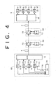
- FIG. 4 is a block diagram of another WDM system to which the present invention is applicable.
- This system includes a transmitting station 66 for outputting WDM signal light, an optical fiber transmission line 4 for transmitting the WDM signal light output from the transmitting station 66, and a receiving station 6 for receiving the WDM signal light transmitted through the optical fiber transmission line 4.
- Two optical repeaters 68 are provided in the optical fiber transmission line 4. Three or more optical repeaters 68 may be provided or one optical repeater 68 may be provided.
- Each optical repeater 68 has an optical amplifier 70 and a SV circuit 72 for inputting/outputting supervisory information directly from/to the optical amplifier 70.
- optical transmitter 8 (#5) for mainly transmitting the supervisory information in the system shown in FIG. 1 is not used in this preferred embodiment. That is, optical transmitters 8 (#1 to #4) included in the transmitting station 66 can output optical signals, modulated by transmission data having wavelengths ⁇ 1 to ⁇ 4 , respectively. Status signals representing the operational conditions of the optical transmitters 8 (#1 to #4) are supplied to a SV circuit 74.
- the SV circuit 74 generates a tone signal according to the supervisory information including the number of channels of the WDM signal light. This tone signal has a frequency sufficiently lower than that of a main signal (transmission data in each optical transmitter 8).
- the tone signal is supplied from the SV circuit 74 through a low-pass filter 76 to the optical transmitter 8 (#4).
- the tone signal is superimposed on a modulating signal (transmission data) to be supplied from a terminal 10 to the optical transmitter 8 (#4).
- a tone signal 80 having a speed sufficiently lower than that of a main signal 78 is superimposed on one of the WDM optical signals.
- the tone signal 80 may be obtained by performing modulation based on the supervisory information with low-frequency tone components used as a subcarrier.
- the frequencies of the tone components are set to 1 KHz to 1 MHz, for example, so that each frequency component is not attenuated in the optical amplifier.
- such a technique for superimposing the tone signal is known as a subcarrier overmodulation technique.
- FIG. 6 there is shown a block diagram showing a second preferred embodiment of the optical repeater.
- This optical repeater may be used as each optical repeater 68 shown in FIG. 4.
- This optical repeater has a feedback loop including an ALC circuit 48. This loop is the same as that shown in FIG. 2, so the description thereof will be omitted herein.
- the WDM signal light supplied from the upstream optical fiber transmission line 4 is branched into first branch light and second branch light by an optical coupler 82.
- the first branch light from the optical coupler 82 is supplied to an optical amplifying medium 38.
- the WDM signal light amplified by the optical amplifying medium 38 is transmitted through an optical coupler 42 to the downstream optical fiber transmission line 4.
- the second branch light from the optical coupler 82 is supplied to an optical band-pass filter 84.
- the filter 84 has a pass band including the wavelengths of the WDM signal light.
- the light output from the filter 84 is supplied to an O/E converter 86.
- An output signal from the O/E converter 86 is supplied to a band-pass filter 88.
- the filter 88 has a pass band including the carrier frequency of the tone signal. Accordingly, the tone signal is extracted by the filter 88, and is then supplied to a SV circuit 90.
- the supervisory information is regenerated according to the tone signal, and a signal SC giving the number of channels obtained according to the supervisory information is supplied from the SV circuit 90 to the ALC circuit 48.
- a reference voltage V REF (see FIG. 3) is set according to the signal SC giving the number of channels. Accordingly, optical output power per channel can be maintained constant irrespective of a change in the number of channels.
- the tone signal is superimposed on only the optical signal having the wavelength ⁇ 4 to be output from the optical transmitter 8 (#4) in the system shown in FIG. 4, the tone signal may be superimposed on all the channels of the WDM signal light.
- an optical modulator is provided between the optical multiplexer 16 and the optical transmission line 4 to thereby superimpose the tone signal on the WDM signal light.
- the number of channels being operated may be transmitted according to the frequency of the tone signal. That is, when only one channel is in operation, a tone signal of 10 KHz is superimposed; when two channels are in operation, a tone signal of 11 KHz is superimposed; when three channels are in operation, a tone signal of 12 KHz is superimposed; and so on.
- the number of channels is detected according to the frequency of the tone signal.
- the frequencies of tone signals may be previously assigned to all the channels, and the tone signals may be superimposed on the corresponding channels before carrying out wavelength-division multiplexing.
- the number of channels being operated can be detected according to the number of frequency components of the tone signals.
- FIG. 7 is a block diagram of still another WDM system to which the present invention is applicable.
- This system includes a transmitting station 92 for outputting WDM signal light, an optical fiber transmission line 4 for transmitting the WDM signal light output from the transmitting station 92, and a receiving station 6 for receiving the WDM signal light transmitted through the optical fiber transmission line 4.
- Two optical repeaters 94 are provided in the optical fiber transmission line 4. Three or more optical repeaters 94 may be provided or one optical repeater 94 may be provided.
- Each optical repeater 94 has an optical amplifier 96 for amplifying the WDM signal light and an ALC circuit 100 for controlling the optical amplifier 96 so that the output level of the optical amplifier 96 becomes a target level.
- a part of the WDM signal light output from the optical amplifier 96 is branched off by an optical coupler 98, and the ALC circuit 100 controls the optical amplifier 96 so that the power of the branch light from the optical coupler 98 becomes constant.
- the transmitting station 92 has five optical transmitters 8 (#1 to #5) capable of generating optical signals having different wavelengths, and an optical multiplexer 16 for wavelength-division multiplexing the optical signals to output WDM signal light.
- the three optical transmitters 8 (#1 to #3) are in operation, and the other two optical transmitters (#4 and #5) are not in operation. That is, pulse signals corresponding to main signals are supplied to drive terminals 10 of the optical transmitters 8 (#1 to #3), and DC biases are supplied to drive terminals 10 of the other optical transmitters 8 (#4 and #5). Accordingly, the optical signals to be output from the optical transmitters 8 (#1 to #3) are modulated by the respective main signals, and the light to be output from the optical transmitters 8 (#4 and #5) is CW light (continuous wave light).
- the reason why the optical transmitters 8 (#4 and #5) not being operated are intended to output the CW light having no relation to the main signals is to make constant the total power of the WDM signal light to be supplied to each optical repeater 94.
- the target level in the ALC circuit 100 can'be maintained constant in each optical repeater 94 irrespective of the number of channels being operated. According to this preferred embodiment, it is therefore unnecessary to change the target level for ALC in each optical repeater 94, thereby allowing the ALC circuit to be simplified.
- the subject to be controlled by the ALC circuit 100 may be set as the power of pump light to be supplied to an EDF.
- the subject to be controlled by the ALC circuit 100 may be set as the attenuation factor of an optical attenuator (not shown) provided upstream or downstream of the optical amplifier 96.
- FIG. 8 is a block diagram showing a third preferred embodiment of the optical repeater.
- This optical repeater may be used instead of each optical repeater 68 in the WDM system shown in FIG. 4.
- This optical repeater has a feedback loop for ALC.
- An ALC circuit 102 included in this loop controls the power of pump light in pumping means 40 so that the output level of the optical amplifier becomes a target level.
- the target level is constant irrespective of the number of channels of the WDM signal light.
- this preferred embodiment employs a compensation light source 104 for outputting compensation light having a wavelength included in the amplification band but different from the wavelengths of the WDM signal light.
- the first branch light from the optical coupler 82 and the compensation light from the light source 104 are combined together in an optical coupler 106, and then supplied to an optical amplifying medium 38.
- the second branch light from the optical coupler 82 is supplied to an optical band-pass filter 84 having a pass band including the wavelengths of the WDM signal light.
- the light output from the filter 84 is supplied to an O/E converter 86.
- the output signal from the O/E converter 86 includes a tone signal modulated by supervisory information.
- This tone signal is extracted by a band-pass filter 88 and supplied to a SV circuit 108.
- the SV circuit 108 controls the power of the compensation light to be output from the compensation light source 104 according to the number of channels of the WDM signal light determined by regeneration of the supervisory information, thereby maintaining constant the target level in the ALC circuit 102 irrespective of the number of channels being operated.
- the compensation light and the WDM signal light are supplied to the optical amplifying medium 38. Accordingly, by setting the power of the compensation light according to the number of channels being operated, it is unnecessary to change the target level in the ALC circuit 102.
- FIG. 9 is a block diagram showing a fourth preferred embodiment of the optical repeater.
- This optical repeater may be used instead of each optical repeater 68 in the WDM system shown in FIG. 4.
- This optical repeater has a feedback loop including an ALC circuit 102 similar to that shown in FIG. 8 and another feedback loop.
- the compensation light from a compensation light source 104 is added to WDM signal light in an optical coupler 106, and output light from the optical coupler 106 is supplied through an optical coupler 110 to an optical amplifying medium 38.
- the filter 112 has a pass band including the wavelengths of the WDM signal light and the wavelength of the compensation light.
- Output light from the filter 112 is input to an O/E converter 114.
- a SV circuit 116 controls the power of the compensation light so that the output level of the O/E converter 114 becomes constant.
- the total power of the WDM signal light and the compensation light to be supplied to the optical amplifying medium 38 is reflected on the output level of the O/E converter 114. Accordingly, by providing such a feedback loop upstream of the optical amplifying medium 38, the total power of the WDM signal light and the compensation light can be maintained constant. By thus maintaining the total power constant, the target level in the ALC circuit 102 can be made constant irrespective of the number of channels of the WDM signal light, thereby allowing the ALC circuit 102 to be simplified. By thus providing the feedback loop including the SV circuit 116, this optical repeater in this preferred embodiment need not receive information on the number of channels of the WDM signal light. Accordingly, in the case that the optical repeater shown in FIG. 9 is applied to the system shown in FIG. 4, the SV circuit 74 in the transmitting station 66 shown in FIG. 4 may be omitted.
- the ALC circuit 102 controls the power of the pump light in the pumping means 40.
- the ALC circuit 102 may control the attenuation factor of an optical attenuator (not shown) provided upstream or downstream of the optical amplifying medium 38.
- FIG. 10 is a block diagram showing a first basic configuration of the optical amplifier according to the present invention.
- the optical amplifier shown in FIG. 10 has an optical amplifying medium 38 and pumping means 40.
- signal light 130 is supplied to a first end 38A of the optical amplifying medium 38 being pumped
- amplified signal light 132 is output from a second end 38B of the optical amplifying medium 38.
- ASE amplified spontaneous emission
- the ASE is output not only from the second end 38B in the same direction as the propagation direction of the signal light 132, but also from the first end 38A in the direction opposite to the propagation direction of the signal light 132 as shown by 134.
- the ASE 134 propagating opposite to the signal light 132 is extracted by ASE extracting means 136.
- monitoring means 138 monitors spectral characteristics giving the wavelength dependence of the power of the ASE 134.
- Parameter control means 140 controls a parameter on which the gain tilt in the amplification band of the optical amplifying medium 38 is dependent (or the gain itself) so that the spectral characteristics monitored above are maintained.
- a doped fiber doped with a rare earth element such as an EDF
- a semiconductor chip may be used (semiconductor optical amplifier).
- the pumping means 40 includes means for injecting a current into the chip. Specifically, a pumping voltage is applied across a pair of electrodes of the semiconductor optical amplifier.
- the pumping means 40 suitable for the doped fiber includes a pump light source for outputting pump light, and optical coupling means operatively connected to at least one of the first end 38A and the second end 38B of the optical amplifying medium 38 to supply the pump light to the optical amplifying medium 38.
- optical components are operatively connected to each other includes the case that the optical components are directly connected together by fiber connection or spatial connection using a collimated beam, and further includes the case that the optical components are connected through another optical component such as an optical filter.
- the pumping means 40 includes the pump light source
- the power of the pump light may be adopted as the parameter to be controlled by the parameter control means 140.
- the pump light source cannot be included in a feedback loop of ALC for making constant the power of the amplified signal light 132 (total gain of the optical amplifier). Therefore, in performing the ALC, a feedback loop including an optical attenuator having a variable attenuation factor may be provided.
- this optical amplifier includes a compensation light source 142 for supplying to the optical amplifying medium 38 compensation light having a wavelength included in the amplification band of the optical amplifying medium 38
- the parameter to be controlled by the parameter control means 140 may be the power of the compensation light.
- the pump light source can be included in the feedback loop for the ALC.
- the wavelength of the compensation light is set different from the wavelength of the signal light.
- WDM signal light is supplied into the optical amplifying medium 38 from the first end 38A.
- Gain characteristics of the optical amplifying medium 38 i.e., the gain tilt
- the spectral characteristics of the ASE 134 are not influenced by the number of channels of WDM signal light, input level, and accumulated ASE in principle. Accordingly, by controlling the parameter on which the gain tilt depends so that the spectral characteristics of the ASE 134 are maintained, a constant gain tilt can be easily obtained. Specific embodiments of a monitoring method for the spectral characteristics will be hereinafter described.
- the first basic configuration of the optical amplifier shown in FIG. 10 has an optical band-pass filter 143 operatively connected to the second end 38B of the optical amplifying medium 38.
- the effectiveness of the filter 143 will now be described.
- the spectral characteristics of forward ASE propagating in the same direction as the propagation direction of the signal light in the optical amplifying medium 38 are influenced by the input level of the signal light and accumulated ASE.
- the spectral characteristics of backward ASE propagating in the direction opposite to the propagation direction of the signal light in the optical amplifying medium 38 are not influenced by these factors in principle.
- the optical band-pass filter 143 having a proper pass band is used.
- the shortest wavelength ⁇ L in the pass band is set slightly shorter than the shortest wavelength of the WDM signal light, and the longest wavelength ⁇ H in the pass band is set slightly longer than the longest wavelength of the WDM signal light. With this setting, the power of accumulated ASE can be effectively reduced.
- the monitoring means 138 shown in FIG. 10 has two optical band-pass filters having different pass bands (e.g., optical band-pass filters 170 and 172 of a spectrum monitor shown in FIG. 14).
- the shortest wavelength and the longest wavelength in the pass band of one of the two filters are set to ⁇ L - ⁇ and ⁇ L , respectively, whereas the shortest wavelength and the longest wavelength in the pass band of the other filter are set to ⁇ H and ⁇ H + ⁇ , respectively.
- FIG. 12 is a block diagram showing a first preferred embodiment of the optical amplifier according to the present invention.
- Signal light to be amplified is supplied through an optical coupler 144 into an optical amplifying medium 38 from its first end 38A.
- the ASE propagating in the direction opposite to the signal light in the optical amplifying medium 38 is extracted by the optical coupler 144.
- the extracted ASE is supplied to a spectrum monitor 146.
- As the optical coupler 144 a fiber fused type of optical coupler, a WDM coupler that is a special form of this type of optical coupler, or an optical circulator may be used.
- a laser diode 148 as a pump light source is used to pump the optical amplifying medium (e.g., doped fiber) 38.
- Pump light output from the laser diode 148 is supplied to the optical amplifying medium 38 through an optical coupler 150 connected to a second end 38B of the optical amplifying medium 38.
- the laser diode 148 is supplied with a bias current from a drive circuit 152.
- the power of the pump light can be controlled according to the bias current.
- the ASE spectral characteristics monitored by the spectrum monitor 146 is supplied to a control circuit 154.
- the control circuit 154 controls the bias current to be supplied from the drive circuit 152 to the laser diode 148 so that the spectral characteristics from the spectrum monitor 146 are maintained.
- the bias current for the laser diode 148 for outputting the pump light is included in a feedback loop for maintaining the gain tilt. Accordingly, ALC cannot be performed by using the bias current for the laser diode 148.
- the amplified signal light output from the second end 38B of the optical amplifying medium 38 through the optical coupler 150 is input into an optical attenuator 156.
- the attenuation factor of the optical attenuator 156 is variable.
- the light output from the optical attenuator 156 is branched into first branch light and second branch light by an optical coupler 158.
- the first branch light from the optical coupler 158 is output to an optical transmission line (not shown).
- the second branch light from the optical coupler 158 is supplied to an optical band-pass filter 160 having a pass band including the wavelength of the signal light.
- Output light from the filter 160 is converted into an electrical signal by an O/E converter 162.
- An ALC circuit 164 controls the attenuation factor of the optical attenuator 156 so that the output level of the O/E converter 162 becomes constant.
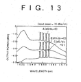
- FIG. 13 is a graph for illustrating an example of the gain tilt in the optical amplifier shown in FIG. 12.
- the spectra of output beams when WDM signal beams each having four channels of wavelengths of 1548 nm, 1551 nm, 1554 nm, and 1557 nm are input with the same input power (-35 dBm/ch) into an EDF being pumped.
- the vertical axis represents output power (dBm) and the horizontal axis represents wavelength (nm).
- the spectrum shown by A corresponds to the case where the power of pump light is relatively large. In this case, a negative gain tilt occurs. That is, the differential of gain with respect to wavelength is negative (dG/d ⁇ ⁇ 0).
- the spectrum shown by C corresponds to the case where the power of pump light is relatively small. In this case, a positive gain tilt is obtained (dG/d ⁇ > 0).
- Each spectrum shown in FIG. 13 has such a shape that four sharp spectra corresponding to the four channels of each WDM signal light are superimposed on a spectrum of ASE.
- the spectrum monitor 146 can monitor the ASE spectrum with a high accuracy without the influence of the power of the WDM signal light.
- P ASE ( ⁇ ) denote the power of backward ASE, it is given by Eq. (1), which is a function of wavelength ⁇ .
- P ASE ( ⁇ 0 ) 2n SP ( ⁇ 0 )h(C/ ⁇ 0 ) [G( ⁇ 0 )- 1] ⁇
- n SP ( ⁇ 0 ) is the spontaneous emission factor
- h is the Planck constant
- C is the velocity of light in a vacuum
- ⁇ 0 is the center wavelength in a band to be monitored
- ⁇ is the bandwidth of the band to be monitored.
- the wavelength dependence of each parameter is substantially constant in the range of ⁇ , so that ⁇ 0 is used as a representative.
- the spontaneous emission factor n SP ( ⁇ 0 ) has wavelength dependence, and a method of improving a monitoring accuracy so as to cope with this wavelength dependence will be hereinafter described.
- G( ⁇ 0 ) represents the gain to be given as a function of wavelength.
- gain characteristics wavelength dependence of gain
- gain characteristics can be evaluated by cutting out two or more narrow bands included in an amplification band, individually detecting the powers in these narrow bands, and obtaining a deviation between detected values.
- first optical band-pass filter having a first narrow pass band included in an amplification band, for receiving the first branch light
- second optical band-pass filter having a second narrow pass band included in the amplification band but different from the first pass band, for receiving the second branch light
- first and second photodetectors for respectively receiving lights passed through the first and second optical band-pass filters, and means for detecting a deviation between output levels of the first and second photodetectors.
- FIG. 14 is a block diagram showing a preferred embodiment of the spectrum monitor 146 shown in FIG. 12.
- the backward ASE generated from the optical amplifying medium 38 (see FIG. 12) is supplied through an optical isolator 166 to an optical coupler 168. If reflection from a backward ASE monitoring system is low, the optical isolator 166 is unnecessary.
- the optical coupler 168 branches the input backward ASE into first branch beam and second branch beam. A branching ratio between the first branch beam and the second branch beam is set to 1:1, for example.
- the first and second branch beams are respectively supplied to optical band-pass filters 170 and 172. In the case that the backward ASE has a spectrum similar to the ASE spectrum as shown in FIG.
- the center wavelengths in the pass bands of the filters 170 and 172 are respectively set to 1541 nm and 1559 nm, for example.
- the beams passed through the filters 170 and 172 are respectively supplied to photodiodes 174 and 176. Since output signals from the photodiodes 174 and 176 are current signals, I/V converters (current/voltage converters) 178 and 180 respectively corresponding to the photodiodes 174 and 176 are used. Output voltage signals from the I/V converters 178 and 180 are respectively supplied to a minus input port and a plus input port of an operational amplifier 182. As a result, an output signal from the operational amplifier 182 reflects a deviation between the output levels of the photodiodes 174 and 176.
- the gain tilt can be maintained constant.
- the gain tilt can be made flat as shown by B in FIG. 13, for example.
- output signals from I/V converters 178 and 180 are taken through an I/O port 184 into an MPU (microprocessing unit) 186.
- the MPU 186 is connected through the I/O port 184 to a memory 188.
- the MPU 186 receives the output levels of the converters 178 and 180, calculates a deviation between the output levels, and outputs the calculated deviation through the I/O port 184.
- the spontaneous emission factor n SP ( ⁇ 0 ) in Eq. (1) has wavelength dependence, that is, depends on the wavelength ⁇ 0 to be monitored. Accordingly, in the case that higher monitoring accuracies are required, a data table of the spontaneous emission factor n SP ( ⁇ 0 ) using wavelength as a parameter may be previously stored in the memory 188 to obtain accurate spectral characteristics according to the data table. For example, the gain G( ⁇ ) can be accurately calculated according to a calculated value of the deviation.
- the two narrow bands are cut out from the amplification band.
- three or more optical band-pass filters may be used to cut out three or more narrow bands corresponding to the number of the optical band-pass filters from the amplification band. In this case, the accuracy of monitoring of the backward ASE to be calculated by the MPU 186 can be improved, for example.
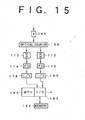
- FIG. 15A is a block diagram showing a concrete example of the optical amplifier shown in FIG. 12.
- an EDF(erbium doped fiber) 39 is used as the optical amplifying medium 38.
- an optical isolator 145A is provided on the input side of the optical coupler 144, and another optical isolator 145B is provided between the optical coupler 150 and the optical attenuator 156.
- the pump light from the laser diode 148 propagates in the direction opposite to the signal light in the EDF 39. That is, backward pumping is adopted. Alternatively, forward pumping may be adopted such that the pumping light propagates in the same direction as the signal light. Further, pump light beams may be supplied into the EDF 39 from both ends thereof, thereby improving a pumping efficiency.
- FIG. 15B is a block diagram showing an optical amplifier to which the forward pumping is adopted.
- an optical coupler 150' is provided on the input side of the optical isolator 145A.
- the pump light from the laser diode 148 and the signal light to be amplified are supplied to the EDF 39 through the optical coupler 150', the optical isolator 145A, and the optical coupler 144.
- FIG. 16 is a block diagram showing a second preferred embodiment of the optical amplifier according to the present invention.
- the optical amplifier shown in FIG. 16 is characterized in that an optical attenuator 156' for ALC is provided upstream of the optical amplifying medium 38. That is, signal light to be input into the optical amplifying medium 38 from its first end 38A is preliminarily attenuated rather than attenuating amplified signal light.
- the attenuation factor of the optical attenuator 156' is controlled by an ALC circuit 164 so that an output level of an O/E converter 162 corresponding to an output level of this optical amplifier becomes constant.
- a constant gain tilt can be maintained, and ALC can also be performed.
- FIG. 17 is a block diagram showing a third preferred embodiment of the optical amplifier according to the present invention.
- This optical amplifier employs a compensation light source for supplying compensation light to the optical amplifying medium 38.
- the power of the compensation light is controlled so that the spectral characteristics of backward ASE are maintained. With this change, the power of pump light is subjected to ALC.
- a laser diode 190 is used as the compensation light source.
- the compensation light from the laser diode 190 is supplied through an optical coupler 192 to the optical amplifying medium 38 from its first end 38A.
- Signal light to be amplified is supplied through an optical coupler 144 for extracting the backward ASE and the optical coupler 192 for the compensation light in this order to the optical amplifying medium 38 from its first end 38A.
- the backward ASE generated in the optical amplifying medium 38 is supplied through the optical coupler 192 and the optical coupler 144 in this order to a spectrum monitor 146.
- the laser diode 190 is supplied with a bias current from a drive circuit 194.
- the bias current to be supplied to the laser diode 190 is controlled by a control circuit 154.
- the control circuit 154 controls the bias current for the laser diode 190 so that the spectral characteristics of the backward ASE monitored by the spectrum monitor 146 are maintained. Accordingly, the power of the compensation light to be output from the laser diode 190 is controlled to maintain constant the gain characteristics of this optical amplifier.
- the power of pump light is not used in the control for maintaining the gain characteristics constant.
- a pump light source can be included in the feedback loop for ALC. Since the compensation light is used for maintenance of the spectral characteristics, the compensation light is removed by an optical filter 160, and output light from the optical filter 160 is converted into an electrical signal by an O/E converter 162.
- a laser diode 148 as the pump light source is supplied with a bias current from a drive circuit 152. The bias current is controlled by an ALC circuit 164.
- a constant gain tilt can be maintained, and ALC can be performed. Further, an optical attenuator for ALC is unnecessary in the third preferred embodiment.
- FIG. 18 is a block diagram showing a fourth preferred embodiment of the optical amplifier according to the present invention.
- reflecting mirrors 196 and 198 are operatively connected to the second end 38B of the optical amplifying medium 38, so as to improve the accuracy of monitoring of the spectral characteristics of backward ASE in the spectrum monitor 146.
- the spectrum monitor 146 is configured as shown in FIG. 14, the reflecting mirror 196 reflects light having a wavelength included in the pass band of the optical band-pass filter 170 and transmits other light, and the reflecting mirror 198 reflects light having a wavelength included in the pass band of the optical band-pass filter 172 and transmits other light.
- the reflecting mirrors 196 and 198 By providing the reflecting mirrors 196 and 198, a part of the forward ASE output from the second end 38B of the optical amplifying medium 28 falling within a specific band can be reciprocated in the optical amplifying medium 38. Accordingly, the input powers into the photodiodes 174 and 176 shown in FIG. 14 can be increased to thereby improve the spectrum monitoring accuracy. In the case that three or more narrow bands are cut out from the ASE spectrum, three or more reflecting mirrors corresponding to the number of the narrow bands are used.
- SE spontaneous emission
- the gain characteristics in the doped fiber are reflected in the SE.
- the SE leaking sideways is not influenced by the number of channels of WDM signal light, input level, and , accumulated ASE. This fact has been reported by Aida et al. in the International Conference, 1991 (Optical Amplifiers and their Applications; OAA, FE3), in which it has become apparent that gain G( ⁇ ) can be obtained from an integral P SE ( ⁇ ) of SE from a side surface of a doped fiber over the fiber length L in accordance with Eqs. (2) and (3).
- FIG. 19 is a block diagram showing a second basic configuration of the optical amplifier according to the present invention.
- An optical amplifying medium 38 has an optical waveguide structure to which signal light is supplied.
- Pumping means 40 pumps the optical amplifying medium 38 so that the optical amplifying medium 38 has an amplification band including the wavelength of the signal light.
- SE extracting means 200 extracts SE light leaking sideways from the optical waveguide structure of the optical amplifying medium 38.
- Monitoring means 138 monitors spectral characteristics giving the wavelength dependence of the power of the extracted SE.
- Parameter control means 140 controls a parameter on which the gain tilt in the amplification band of the optical amplifying medium 38 depends (or gain itself) so that the spectral characteristics monitored are maintained.
- the parameter to be controlled by the parameter control means 140 is the power of pump light in the pumping means 40.
- the parameter to be controlled by the parameter control means 140 may be the power of compensation light like in FIG. 10.
- FIG. 20 is a block diagram of a spectrum monitor that can be used as the SE extracting means 200 and the monitoring means 138 shown in FIG. 19.
- An EDF 202 is used as the optical amplifying medium 38 (see FIG. 19). Means for pumping the EDF 202 is not shown.
- the EDF 202 is accommodated in a case 204 such as an integrating sphere configured so as to block entering of external light. A cover of the EDF 202 is partially removed, and SE leaks sideways from an uncovered portion of the EDF 202.
- the SE is supplied to optical band-pass filters 206 and 208.
- the filters 206 and 208 have their pass bands similar to the pass bands of the optical band-pass filters 170 and 172 shown in FIG. 15, respectively.
- the beams passed through the filters 206 and 208 are converted into current signals by photodiodes 210 and 212, respectively.
- the current signals from the photodiodes 210 and 212 are next converted into voltage signals by I/V converters 214 and 216, respectively.
- the voltage signals from the I/V converters 214 and 216 are supplied to an operational amplifier 218.
- the gain characteristics of the optical amplifier are reflected on the SE spectrum. Accordingly, by controlling the power of pump light according to the SE spectral characteristics monitored, the gain tilt of the optical amplifier can be maintained constant.
- the spectrum monitor shown in FIG. 20 may be modified according to the configuration shown in FIG. 15. That is, an MPU is used for monitoring of the spectral characteristics. In this case, by previously storing C( ⁇ ), ⁇ s , and L in Eqs. (2) and (3) in a memory, the monitoring accuracy of the spectral characteristics can be improved. Further, three or more narrow bands may be cut out from the SE spectrum, and optical power in each band may be detected to perform various controls according to the result of detection.
- FIG. 21 is a block diagram showing a third basic configuration of the optical amplifier according to the present invention.
- This optical amplifier is configured by cascading a first optical amplifier unit 220 and a second optical amplifier unit 222.
- Each of the optical amplifier units 220 and 222 has the first basic configuration shown in FIG. 10.
- Light amplified in the first optical amplifier unit 220 is attenuated by an optical attenuator 224 having a variable attenuation factor, and next transmitted through a dispersion compensating fiber (DCF) 226 to the second optical amplifier unit 222.
- the DCF 226 has a dispersion value so as to cancel chromatic dispersion influenced the signal light in a transmission line.
- the light output from the second optical amplifier unit 222 is branched into first branch light and second branch light by an optical coupler 228.
- the first branch light from the optical coupler 228 is output to an optical transmission line (not shown).
- the second branch light from the optical coupler 228 is converted into an electrical signal by an O/E converter 230.
- An ALC circuit 232 controls the attenuation factor of the optical attenuator 224 so that the output level of the O/E converter 230 is maintained constant.
- Such a two-stage configuration of the optical amplifier in this preferred embodiment is due to the following reasons.
- the first reason is that a loss in a DCF is large in general, and it is therefore necessary to raise the level of the signal light to some extent on the upstream side of the DCF 226.
- the second reason is that if an optical amplifier gain on the upstream side of the DCF 226 is made excess to increase the power of the signal light, nonlinear effects are prone to occur in the DCF 226.
- FWM four-wave mixing
- SPM self-phase modulation
- a constant gain tilt can be maintained, and ALC can also performed.
- an optical communication system which can easily respond to a change in the number of WDM channels.
Landscapes
- Engineering & Computer Science (AREA)
- Computer Networks & Wireless Communication (AREA)
- Signal Processing (AREA)
- Physics & Mathematics (AREA)
- Electromagnetism (AREA)
- Plasma & Fusion (AREA)
- Optics & Photonics (AREA)
- Optical Communication System (AREA)
- Lasers (AREA)
Applications Claiming Priority (3)
| Application Number | Priority Date | Filing Date | Title |
|---|---|---|---|
| JP13824396 | 1996-05-31 | ||
| JP8138243A JPH09321701A (ja) | 1996-05-31 | 1996-05-31 | 光通信システム及び光増幅器 |
| EP96119965A EP0812078B1 (de) | 1996-05-31 | 1996-12-12 | Optisches Übertragungssystem und optischer Verstärker |
Related Parent Applications (1)
| Application Number | Title | Priority Date | Filing Date |
|---|---|---|---|
| EP96119965A Division EP0812078B1 (de) | 1996-05-31 | 1996-12-12 | Optisches Übertragungssystem und optischer Verstärker |
Publications (2)
| Publication Number | Publication Date |
|---|---|
| EP1439655A2 true EP1439655A2 (de) | 2004-07-21 |
| EP1439655A3 EP1439655A3 (de) | 2005-05-04 |
Family
ID=15217427
Family Applications (3)
| Application Number | Title | Priority Date | Filing Date |
|---|---|---|---|
| EP04009662A Withdrawn EP1439655A3 (de) | 1996-05-31 | 1996-12-12 | Optisches Übertragungssystem und optischer Verstärker |
| EP04009661A Expired - Lifetime EP1439654B1 (de) | 1996-05-31 | 1996-12-12 | Optisches Übertragungssystem und optischer Verstärker |
| EP96119965A Expired - Lifetime EP0812078B1 (de) | 1996-05-31 | 1996-12-12 | Optisches Übertragungssystem und optischer Verstärker |
Family Applications After (2)
| Application Number | Title | Priority Date | Filing Date |
|---|---|---|---|
| EP04009661A Expired - Lifetime EP1439654B1 (de) | 1996-05-31 | 1996-12-12 | Optisches Übertragungssystem und optischer Verstärker |
| EP96119965A Expired - Lifetime EP0812078B1 (de) | 1996-05-31 | 1996-12-12 | Optisches Übertragungssystem und optischer Verstärker |
Country Status (6)
| Country | Link |
|---|---|
| US (5) | US6023366A (de) |
| EP (3) | EP1439655A3 (de) |
| JP (1) | JPH09321701A (de) |
| KR (1) | KR100210969B1 (de) |
| CN (1) | CN1084558C (de) |
| DE (2) | DE69636708T2 (de) |
Cited By (1)
| Publication number | Priority date | Publication date | Assignee | Title |
|---|---|---|---|---|
| WO2019196884A1 (en) * | 2018-04-11 | 2019-10-17 | Huawei Technologies Co., Ltd. | System and method for optical channel reconfiguration |
Families Citing this family (237)
| Publication number | Priority date | Publication date | Assignee | Title |
|---|---|---|---|---|
| US6025947A (en) * | 1996-05-02 | 2000-02-15 | Fujitsu Limited | Controller which controls a variable optical attenuator to control the power level of a wavelength-multiplexed optical signal when the number of channels are varied |
| JPH09321701A (ja) * | 1996-05-31 | 1997-12-12 | Fujitsu Ltd | 光通信システム及び光増幅器 |
| US6369938B1 (en) | 1996-05-28 | 2002-04-09 | Fujitsu Limited | Multi-wavelength light amplifier |
| GB2314714B (en) * | 1996-06-26 | 2000-04-05 | Northern Telecom Ltd | Optical amplifier modules |
| JP2904131B2 (ja) * | 1996-07-04 | 1999-06-14 | 日本電気株式会社 | 波長多重光増幅装置と波長多重光伝送装置 |
| SE9603337L (sv) | 1996-09-13 | 1997-12-15 | Ericsson Telefon Ab L M | Transmissionssystem med återkopplad optisk förstärkare |
| US6128111A (en) * | 1996-12-19 | 2000-10-03 | Nortel Networks Corporation | Monitoring of nonlinear effects |
| KR100229711B1 (ko) * | 1996-12-31 | 1999-11-15 | 서평원 | 파장 분할 다중화 시스템의 채널 전력 제어장치 |
| JP3860278B2 (ja) * | 1997-03-13 | 2006-12-20 | 富士通株式会社 | 遠隔励起方式の波長多重光伝送システム |
| US6452701B1 (en) * | 1997-03-19 | 2002-09-17 | Fujitsu Limited | Wavelength division multiplexing communications network supervisory system |
| JP3068500B2 (ja) * | 1997-04-25 | 2000-07-24 | 日本電気株式会社 | 光信号増幅伝送方式 |
| JPH10303821A (ja) * | 1997-04-25 | 1998-11-13 | Nec Corp | 光信号増幅伝送方式 |
| JPH10327108A (ja) * | 1997-05-23 | 1998-12-08 | Nec Corp | Nb−wdmシステムおよびnb−wdmシステムの波長数設定方式 |
| JPH10341206A (ja) * | 1997-06-06 | 1998-12-22 | Nec Corp | 波長多重伝送装置 |
| JP3542253B2 (ja) * | 1997-06-19 | 2004-07-14 | 株式会社日立コミュニケーションテクノロジー | 光ファイバ増幅器およびそれを用いた光伝送システム |
| KR100219719B1 (ko) | 1997-07-15 | 1999-09-01 | 윤종용 | 감시가능한 파장분할다중화 광증폭기 제어시스템 및 그 제어방법 |
| US6222654B1 (en) * | 1997-08-04 | 2001-04-24 | Lucent Technologies, Inc. | Optical node system for a ring architecture and method thereof |
| KR100265792B1 (ko) | 1997-09-26 | 2000-09-15 | 윤종용 | 파장분할다중전송시스템및그전송방법 |
| JP3522509B2 (ja) * | 1997-10-17 | 2004-04-26 | 富士通株式会社 | 光伝送装置及び光通信システム |
| SE9703000D0 (sv) * | 1997-10-21 | 1997-08-20 | Ericsson Telefon Ab L M | Optical amplifier control |
| JP3884841B2 (ja) | 1997-11-14 | 2007-02-21 | 株式会社日立コミュニケーションテクノロジー | 光伝送システム及び光通信装置 |
| JP3549716B2 (ja) * | 1997-11-28 | 2004-08-04 | 日本電気株式会社 | 光adm装置 |
| KR100292334B1 (ko) * | 1997-12-30 | 2001-07-12 | 서평원 | 더블유디엠시스템에서채널감시장치및방법 |
| JP3166695B2 (ja) | 1998-01-05 | 2001-05-14 | 日本電気株式会社 | 波長分割多重送信装置 |
| JPH11202374A (ja) | 1998-01-14 | 1999-07-30 | Fujitsu Ltd | 波長多重システムにおける光通信端局、光信号伝送方法、及び光信号の増設方法 |
| JP3779054B2 (ja) | 1998-01-23 | 2006-05-24 | 富士通株式会社 | 可変光学フィルタ |
| US6275313B1 (en) * | 1998-02-03 | 2001-08-14 | Lucent Technologies Inc. | Raman gain tilt equalization in optical fiber communication systems |
| JP3638777B2 (ja) | 1998-02-04 | 2005-04-13 | 富士通株式会社 | 利得等化のための方法並びに該方法の実施に使用する装置及びシステム |
| KR19990069330A (ko) * | 1998-02-06 | 1999-09-06 | 윤종용 | 채널당 출력파워가 일정한 광증폭기 및 이를위한 방법 |
| CN1255259A (zh) | 1998-02-06 | 2000-05-31 | 富士通株式会社 | 光放大器,用于光放器中的激励光源控制方法,和光放大器控制方法 |
| JP3551407B2 (ja) * | 1998-02-16 | 2004-08-04 | 富士通株式会社 | 波長多重光伝送システム |
| ES2138927B1 (es) * | 1998-02-27 | 2000-09-01 | Telefonica Sa | Extensor de vano optico bidireccional multicanal. |
| US6441955B1 (en) | 1998-02-27 | 2002-08-27 | Fujitsu Limited | Light wavelength-multiplexing systems |
| JPH11252047A (ja) * | 1998-03-04 | 1999-09-17 | Fujitsu Ltd | 光波長多重システム、及びその端局 |
| AU2984599A (en) * | 1998-03-05 | 1999-09-20 | Laser Power Corporation | Coupled cavity laser source for telecommunications |
| JP3532759B2 (ja) * | 1998-03-11 | 2004-05-31 | 富士通株式会社 | Wdm通信システムにおける中継装置及び同装置の送信レベル制御方法 |
| US6603596B2 (en) * | 1998-03-19 | 2003-08-05 | Fujitsu Limited | Gain and signal level adjustments of cascaded optical amplifiers |
| EP0946006B1 (de) | 1998-03-26 | 2001-06-27 | Lucent Technologies Inc. | Verfahren und Vorrichtung zur Steuerung der optischen Leistung eines wellenlängenmultiplexierten übertragenen Signals |
| US6580530B1 (en) * | 1998-05-29 | 2003-06-17 | Cisco Photonics Italy S.R.L. | Optical communication system |
| JP3774066B2 (ja) * | 1998-06-30 | 2006-05-10 | 富士通株式会社 | 光通信システム及びその光信号制御方法 |
| US6728026B2 (en) * | 1998-07-14 | 2004-04-27 | Novera Optics, Inc. | Dynamically tunable optical amplifier and fiber optic light source |
| DE19838788A1 (de) * | 1998-08-26 | 2000-03-09 | Siemens Ag | Geregelter optischer Verstärker |
| US6614567B1 (en) * | 1998-08-31 | 2003-09-02 | Lucent Technologies Inc. | Apparatus and method for upgrading the capacity of wavelength division multiplexed optical networks |
| KR100316308B1 (ko) * | 1998-10-07 | 2002-02-19 | 윤종용 | 채널당출력파워가일정한파장분할다중화광섬유증폭기 |
| EP0994583B1 (de) * | 1998-10-13 | 2001-09-12 | Lucent Technologies Inc. | Verfahren und Vorrichtung zur optischen Leistungsregelung eines optischen Übertragungssignals |
| US6687461B1 (en) * | 1998-11-04 | 2004-02-03 | Board Of Regents, The University Of Texas System | Active optical lattice filters |
| KR100416439B1 (ko) * | 1998-11-24 | 2004-03-30 | 삼성전자주식회사 | 이득평탄도를제어하는광섬유증폭기 |
| US6424439B1 (en) * | 1998-11-24 | 2002-07-23 | Nortel Networks Limited | Wavelength division multiplexed channel tagging |
| KR100283956B1 (ko) * | 1998-11-24 | 2001-04-02 | 윤종용 | 채널별 출력세기가 일정한 광섬유증폭기 및 그 증폭방법 |
| FR2790160B1 (fr) * | 1999-02-19 | 2001-05-04 | Cit Alcatel | Systeme de transmission regenere wdm |
| GB2347809B (en) * | 1999-03-12 | 2001-06-20 | Marconi Comm Ltd | Signal transmission system |
| JP3670156B2 (ja) * | 1999-03-18 | 2005-07-13 | 富士通株式会社 | 監視光信号を伝送するための方法、装置及びシステム |
| JP4204693B2 (ja) | 1999-03-31 | 2009-01-07 | 三菱電機株式会社 | 光増幅装置 |
| DE19917751C2 (de) | 1999-04-20 | 2001-05-31 | Nokia Networks Oy | Verfahren und Überwachungsvorrichtung zur Überwachung der Qualität der Datenübertragung über analoge Leitungen |
| US6801555B1 (en) * | 1999-04-26 | 2004-10-05 | Finisar Corporation | Lasing semiconductor optical amplifier with output power monitor and control |
| US6275329B1 (en) * | 1999-05-10 | 2001-08-14 | Oni Systems Corp. | Method and apparatus for amplification of an optical signal |
| US6215584B1 (en) * | 1999-05-10 | 2001-04-10 | Jds Uniphase Inc. | Input independent tilt free actively gain flattened broadband amplifier |
| US6347008B1 (en) * | 1999-06-14 | 2002-02-12 | Tellium, Inc. | Optical amplifier system and optical network having flattened gain and constant per channel output power |
| KR100326119B1 (ko) * | 1999-06-23 | 2002-03-07 | 윤종용 | 씨드-빔을 이용한 엘-밴드 광섬유 증폭기 |
| JP2001016170A (ja) * | 1999-06-28 | 2001-01-19 | Nec Corp | 光増幅中継器およびこれを用いた出力制御方式 |
| US6275331B1 (en) * | 1999-06-30 | 2001-08-14 | Nortel Networks Limited | Optical amplifiers |
| EP1220388B1 (de) * | 1999-07-09 | 2008-11-19 | Sumitomo Electric Industries, Ltd. | Optischer verstaerker und optisches verstärkungsverfahren |
| US6839163B1 (en) * | 1999-09-01 | 2005-01-04 | Avanex Corporation | Apparatus and method for making an optical fiber amplifier |
| JP3803000B2 (ja) * | 1999-09-28 | 2006-08-02 | 富士通株式会社 | 波長間光パワー偏差のモニタ方法、並びに、それを用いた光等化器および光増幅器 |
| JP4013425B2 (ja) | 1999-10-18 | 2007-11-28 | 富士通株式会社 | 複数波長帯域光増幅器 |
| KR100319779B1 (ko) * | 1999-12-21 | 2002-01-09 | 오길록 | 감시제어채널을 이용한 유도 브릴루앙 산란 억제 장치 및그 방법 |
| US6433903B1 (en) * | 1999-12-29 | 2002-08-13 | Sycamore Networks, Inc. | Optical management channel for wavelength division multiplexed systems |
| US6313940B1 (en) * | 1999-12-31 | 2001-11-06 | Lucent Technologies Inc. | System based control of optical amplifier transmission functions |
| JP2001196670A (ja) * | 2000-01-12 | 2001-07-19 | Oki Electric Ind Co Ltd | 光増幅器 |
| GB0000583D0 (en) * | 2000-01-13 | 2000-03-01 | Sensor Highway Ltd | Optical supply arrangement |
| EP1128504B8 (de) * | 2000-02-23 | 2009-08-12 | Fujitsu Limited | Optischer Verstärker |
| US6634807B1 (en) * | 2000-03-14 | 2003-10-21 | Lucent Technologies Inc. | Optical transmission system including performance optimization |
| JP2001268014A (ja) * | 2000-03-15 | 2001-09-28 | Nec Corp | ブロック利得等化器 |
| US6519081B2 (en) | 2000-04-13 | 2003-02-11 | Corning Incorporated | Method of operating a noise-compensating gain controller for an optical amplifier |
| EP1273077A1 (de) * | 2000-04-13 | 2003-01-08 | Siemens Aktiengesellschaft | Verfahren und vorrichtung zur regelung eines verstärkend wirkenden mediums, insbesondere einer lichtleitfaser |
| JP4234927B2 (ja) | 2000-04-14 | 2009-03-04 | 富士通株式会社 | 光波長多重伝送システム及び光出力制御方法及び光波長多重伝送装置 |
| JP3938270B2 (ja) | 2000-06-29 | 2007-06-27 | 三菱電機株式会社 | 光中継増幅装置 |
| JP2002040495A (ja) | 2000-07-21 | 2002-02-06 | Sumitomo Electric Ind Ltd | ラマン増幅器 |
| JP3363133B2 (ja) * | 2000-07-21 | 2003-01-08 | 住友電気工業株式会社 | 波長多重分割伝送方法およびそのシステム |
| JP3875190B2 (ja) * | 2000-07-31 | 2007-01-31 | 三菱電機株式会社 | 波長分割多重光伝送装置 |
| JP4689015B2 (ja) * | 2000-08-14 | 2011-05-25 | 富士通株式会社 | 光増幅装置および光増幅方法ならびに光通信システム |
| GB2366925A (en) * | 2000-09-13 | 2002-03-20 | Marconi Comm Ltd | Power control and equalisation in an optical WDM system |
| US6311581B1 (en) * | 2000-09-21 | 2001-11-06 | Chao-Jen Hsieh | Automatic optical fiber stripping machine with stripping length control means |
| US6900931B1 (en) * | 2000-10-02 | 2005-05-31 | Ciena Corporation | Three-stage optical amplifier having flat spectral gain |
| AU2002210878A1 (en) * | 2000-10-10 | 2002-04-22 | Trellis Photonics Ltd. | Method, device, and system, for multiple order amplitude modulation of an optical signal, and demodulation thereof |
| US6804464B2 (en) * | 2000-11-01 | 2004-10-12 | Dowslake Microsystems Corporation | Flexible and low cost wavelength management for optical networking |
| US6441950B1 (en) * | 2000-11-03 | 2002-08-27 | Onetta, Inc. | Distributed raman amplifier systems with transient control |
| US7274880B2 (en) * | 2000-11-16 | 2007-09-25 | Tyco Telecommunications (Us) Inc. | Raman assisted EDFA system and method |
| US6542287B1 (en) * | 2000-12-12 | 2003-04-01 | Onetta, Inc. | Optical amplifier systems with transient control |
| US6621625B1 (en) | 2000-12-13 | 2003-09-16 | Avanex Corporation | Optical node including three-stage optical amplifier with automatic gain and level control |
| KR100358115B1 (ko) * | 2000-12-14 | 2002-10-25 | 한국전자통신연구원 | 자동 이득 제어된 광섬유 증폭 장치 |
| JP2002198599A (ja) | 2000-12-22 | 2002-07-12 | Nec Corp | 光増幅器および光増幅方法 |
| JP2002198598A (ja) | 2000-12-22 | 2002-07-12 | Nec Corp | 光増幅利得制御回路および光増幅利得制御方法 |
| JP4388705B2 (ja) * | 2001-01-31 | 2009-12-24 | 富士通株式会社 | 光増幅器 |
| JP3768110B2 (ja) | 2001-02-22 | 2006-04-19 | 富士通株式会社 | 光増幅器 |
| US6906854B1 (en) * | 2001-03-16 | 2005-06-14 | Tyco Telecommunications (Us) Inc. | System and method for controlling noise in raman amplifiers |
| US6535330B1 (en) | 2001-03-31 | 2003-03-18 | Corning Incorporated | Dynamic controller for a multi-channel optical amplifier |
| JP4188573B2 (ja) * | 2001-04-09 | 2008-11-26 | 株式会社日立製作所 | 光増幅器の増幅帯域拡大方法、光増幅器、及び増設ユニット |
| JP3786584B2 (ja) * | 2001-04-20 | 2006-06-14 | 富士通株式会社 | 波長多重用光増幅器の特性測定方法および特性測定システム |
| JP3826726B2 (ja) * | 2001-04-25 | 2006-09-27 | 日本電気株式会社 | 光出力装置の保護装置並びにそれを用いた光伝送システム及び光出力装置の保護方法 |
| WO2002091027A2 (en) * | 2001-05-09 | 2002-11-14 | Ciena Corporation | Method and system for controlling amplifier power in an optical communications network having add/drop capability |
| US6600596B2 (en) * | 2001-05-09 | 2003-07-29 | Ciena Corporation | Method and system for controlling amplifier power in an optical communications network having add/drop capability |
| US6614589B2 (en) | 2001-05-09 | 2003-09-02 | Ciena Corporation | Method and system for controlling amplifier power in an optical communications network |
| US6690506B2 (en) | 2001-05-17 | 2004-02-10 | Corning Incorporated | Control architecture and method for optical amplifiers |
| US6943937B2 (en) | 2001-05-17 | 2005-09-13 | Avanex Corporation | Optical amplifier performance controller and method of use |
| JP2002358378A (ja) * | 2001-06-01 | 2002-12-13 | Fujitsu Ltd | 店舗管理システム |
| US6751014B2 (en) * | 2001-06-19 | 2004-06-15 | International Business Machines Corporation | Automatic gain control and dynamic equalization of erbium doped optical amplifiers in wavelength multiplexing networks |
| JP2003007697A (ja) * | 2001-06-21 | 2003-01-10 | Hitachi Kokusai Electric Inc | 半導体装置の製造方法、基板処理方法および基板処理装置 |
| CA2449563C (en) * | 2001-06-22 | 2011-12-06 | John C. Carrick | System and method for measuring power of optical signals carried over a fiber optic link |
| JP4651231B2 (ja) * | 2001-07-26 | 2011-03-16 | 富士通株式会社 | 光伝送システム |
| US6421168B1 (en) | 2001-07-31 | 2002-07-16 | Seneca Networks | Reduction of ASE in WDM optical ring networks |
| US6388802B1 (en) | 2001-07-31 | 2002-05-14 | Seneca Networks | Reduction of ASE in WDM optical ring networks |
| JP4569064B2 (ja) * | 2001-09-27 | 2010-10-27 | 住友電気工業株式会社 | 光送信機及び波長分割多重伝送システム |
| JP4549591B2 (ja) * | 2001-09-28 | 2010-09-22 | 富士通株式会社 | 装置 |
| JP2003124881A (ja) * | 2001-10-15 | 2003-04-25 | Fujitsu Ltd | 光伝送装置および光伝送システム |
| GB0130214D0 (en) * | 2001-12-18 | 2002-02-06 | Cit Alcatel | Supervisory signalling for optical communications equipment |
| JP3986824B2 (ja) * | 2001-12-28 | 2007-10-03 | 富士通株式会社 | 光フィルタの制御方法及び制御装置並びに光ノード装置 |
| US7058301B2 (en) | 2002-02-28 | 2006-06-06 | Bosloy Jonathan L | Apparatus and method for planned wavelength addition and removal in a wavelength division multiplexed system |
| US7042634B2 (en) * | 2002-03-14 | 2006-05-09 | Nippon Telegraph And Telephone Corporation | Optical amplifier |
| JPWO2003079584A1 (ja) * | 2002-03-19 | 2005-07-21 | 富士通株式会社 | ラマン増幅を用いた光ファイバ伝送のための方法及びシステム |
| US6917731B2 (en) * | 2002-03-27 | 2005-07-12 | Corning Incorporated | Optical amplification module |
| US20030185485A1 (en) * | 2002-03-27 | 2003-10-02 | Bennett Kevin W. | Optical processing module |
| US20040028323A1 (en) * | 2002-03-27 | 2004-02-12 | Bennett Kevin W | Telemetry add/drop module |
| US20040017602A1 (en) * | 2002-03-27 | 2004-01-29 | Bennett Kevin W. | Modular optical amplifier assembly with self identifying modules |
| US20030223683A1 (en) * | 2002-03-27 | 2003-12-04 | Bennett Kevin W. | Modular optical amplifier assembly |
| US20030185483A1 (en) * | 2002-03-27 | 2003-10-02 | Bennett Kevin W. | Optical monitoring and access module |
| US6937385B2 (en) * | 2002-03-27 | 2005-08-30 | Avanex Corporation | Customer interface module |
| US20030184846A1 (en) * | 2002-03-27 | 2003-10-02 | Bennett Kevin W. | Modular optical amplifier assembly and a method of assembly |
| WO2003083623A2 (en) * | 2002-03-28 | 2003-10-09 | Celion Networks, Inc. | Apparatus and method for aggregation and transportation for plesiosynchronous framing oriented data formats |
| US7505687B2 (en) * | 2002-03-29 | 2009-03-17 | Pivotal Decisions Llc | Distributed terminal optical transmission system |
| US7164692B2 (en) | 2002-04-08 | 2007-01-16 | Jeffrey Lloyd Cox | Apparatus and method for transmitting 10 Gigabit Ethernet LAN signals over a transport system |
| US6965738B2 (en) * | 2002-04-16 | 2005-11-15 | Eiselt Michael H | Chromatic dispersion compensation system and method |
| WO2003090035A2 (en) * | 2002-04-22 | 2003-10-30 | Celion Networks, Inc. | Automated optical transport system |
| JP3833564B2 (ja) | 2002-04-24 | 2006-10-11 | 富士通株式会社 | ラマン増幅を用いた光ファイバ伝送のための方法及び装置 |
| US6847678B2 (en) * | 2002-04-25 | 2005-01-25 | Raytheon Company | Adaptive air interface waveform |
| US7460296B2 (en) * | 2002-04-30 | 2008-12-02 | Pivotal Decisions Llc | Compensation for spectral power tilt from scattering |
| US7206516B2 (en) * | 2002-04-30 | 2007-04-17 | Pivotal Decisions Llc | Apparatus and method for measuring the dispersion of a fiber span |
| US7711271B2 (en) * | 2002-04-30 | 2010-05-04 | Eiselt Michael H | Wave division multiplexed optical transport system utilizing optical circulators to isolate an optical service channel |
| US8494372B2 (en) * | 2002-04-30 | 2013-07-23 | Pivotal Decisions Llc | Apparatus and method for optimizing optical and electrical filtering of optical signals |
| US7593637B2 (en) * | 2002-04-30 | 2009-09-22 | Angela Chiu | Optical transport system architecture for remote terminal connectivity |
| US6606191B1 (en) | 2002-05-13 | 2003-08-12 | Corning Incorporated | Method for controlling performance of optical amplifiers |
| US6920277B2 (en) | 2002-06-04 | 2005-07-19 | Marvin R. Young | Optical bypass method and architecture |
| AU2003273529A1 (en) | 2002-06-04 | 2003-12-19 | Celion Networks, Inc. | Flexible, dense line card architecture |
| US7440164B2 (en) * | 2002-06-04 | 2008-10-21 | Pivotal Decisions Llc | Apparatus and method for Raman gain spectral control |
| US7460745B2 (en) * | 2002-06-04 | 2008-12-02 | Pivotal Decisions Llc | Configurable dispersion compensation trimmer |
| US20040042067A1 (en) * | 2002-06-04 | 2004-03-04 | Eiselt Michael H. | Apparatus and method for duplex optical transport using a co-directional optical amplifier |
| US7924496B2 (en) * | 2002-06-04 | 2011-04-12 | Pivotal Decisions Llc | Apparatus and method for Raman gain control |
| US7603042B2 (en) * | 2002-06-04 | 2009-10-13 | Eiselt Michael H | Apparatus and method for optimum decision threshold setting |
| US20050226630A1 (en) * | 2003-06-03 | 2005-10-13 | Celion Networks Inc. | Optical bypass method and architecture |
| US6721091B2 (en) * | 2002-06-13 | 2004-04-13 | Tyco Telecommunications (Us) Inc. | System and method for controlling optical amplifier pumps |
| DE60204561T2 (de) * | 2002-07-22 | 2006-05-11 | Agilent Technologies, Inc. (n.d.Ges.d.Staates Delaware), Palo Alto | Überwachungsdatenübertragung in einem optischen Kommunikationssystem |
| US20040027384A1 (en) * | 2002-08-12 | 2004-02-12 | Gilbert Levesque | End-to-end tracing of wavelength parameters in a wavelength division multiplexing span of a fiber optic network |
| JP4359035B2 (ja) * | 2002-11-21 | 2009-11-04 | 富士通株式会社 | 光中継器 |
| US7421207B2 (en) | 2002-12-13 | 2008-09-02 | Pivotal Decisions Llc | Single fiber duplex optical transport |
| US7656905B2 (en) | 2002-12-24 | 2010-02-02 | Samir Sheth | Apparatus and method for aggregation and transportation of gigabit ethernet and other packet based data formats |
| US7782778B2 (en) * | 2002-12-24 | 2010-08-24 | Samir Satish Sheth | Apparatus and method for fibre channel distance extension embedded within an optical transport system |
| JP2004221968A (ja) * | 2003-01-15 | 2004-08-05 | Fujitsu Ltd | 光伝送方式 |
| KR100526502B1 (ko) * | 2003-05-21 | 2005-11-08 | 삼성전자주식회사 | 반도체 광증폭기 모듈 |
| US7027210B2 (en) * | 2003-05-29 | 2006-04-11 | Fujitsu Limited | Method and system for determining gain for an optical signal |
| US6898347B2 (en) * | 2003-05-30 | 2005-05-24 | Intel Corporation | Monitoring power in optical networks |
| DE10335419A1 (de) * | 2003-08-02 | 2005-02-17 | Marconi Communications Gmbh | Wellenlängenselektive optische Signalverarbeitungsvorrichtung |
| FR2859054B1 (fr) * | 2003-08-19 | 2006-12-29 | Cit Alcatel | Controle dynamique de perte de puissance dans une fibre optique par contrapropagation d'un canal de supervision |
| US7042657B2 (en) * | 2003-08-28 | 2006-05-09 | Board Of Regents The University Of Texas System | Filter for selectively processing optical and other signals |
| US7702030B2 (en) * | 2003-12-17 | 2010-04-20 | Mindspeed Technologies, Inc. | Module to module signaling with jitter modulation |
| JP4340567B2 (ja) * | 2004-03-17 | 2009-10-07 | 富士通株式会社 | 端局装置、光出力パワーの制御方法及び光出力パワー制御プログラム |
| US20050249505A1 (en) * | 2004-05-10 | 2005-11-10 | Richard Manderscheid | Spectral tilt measurement system and method for an optical medium |
| US7526201B2 (en) * | 2004-06-25 | 2009-04-28 | Tyco Telecommunications (Us) Inc. | Optical fiber transmission system with noise loading |
| CN100390585C (zh) * | 2004-07-13 | 2008-05-28 | 杭州恒生普维光电技术有限公司 | 光纤总线结构和光纤总线网 |
| US7583902B2 (en) * | 2004-08-10 | 2009-09-01 | Mindspeed Technologies, Inc. | Module to module signaling utilizing amplitude modulation |
| US7551852B2 (en) * | 2004-08-10 | 2009-06-23 | Mindspeed Technologies, Inc. | Module to module signaling |
| JP4643645B2 (ja) * | 2004-08-11 | 2011-03-02 | タイコ エレクトロニクス サブシー コミュニケーションズ エルエルシー | 光伝送システムにスペクトル負荷を与えるシステム及び方法 |
| US7504610B2 (en) * | 2004-09-03 | 2009-03-17 | Mindspeed Technologies, Inc. | Optical modulation amplitude compensation system having a laser driver with modulation control signals |
| KR100729387B1 (ko) * | 2005-02-25 | 2007-06-15 | (주)에프알텍 | 다채널 저밀도 파장 분할 다중화 시스템에서 반사된 광 신호 감시 장치 및 감시 방법 |
| ATE385087T1 (de) * | 2005-09-26 | 2008-02-15 | Alcatel Lucent | Verfahren zur verstärkung eines zeitvariablen optischen signals und optische verstärkungseinrichtung |
| US7853154B2 (en) * | 2006-01-13 | 2010-12-14 | Mindspeed Technologies, Inc. | Bias circuit for burst-mode/TDM systems with power save feature |
| US7721012B2 (en) * | 2006-01-18 | 2010-05-18 | Mindspeed Technologies, Inc. | Reprogrammable device address for a serial interface in an optic module |
| US7702201B2 (en) * | 2006-06-08 | 2010-04-20 | Industrial Technology Research Institute | Gain flattening utilizing a two-stage erbium-based amplifier |
| JP4882539B2 (ja) * | 2006-06-21 | 2012-02-22 | 日本電気株式会社 | 移動通信システム、ベースバンドサーバ及びそれらに用いる信号中継方法 |
| US7822341B2 (en) * | 2006-09-28 | 2010-10-26 | Alcatel-Lucent Usa Inc. | Coordination of control operations in an optical network |
| JP4940861B2 (ja) * | 2006-09-28 | 2012-05-30 | 富士通株式会社 | Wdm光伝送システム |
| US8995053B2 (en) * | 2006-12-28 | 2015-03-31 | Alcatel Lucent | Positive optical amplifier power transient suppression |
| US8509629B2 (en) * | 2007-10-26 | 2013-08-13 | Mindspeed Technologies, Inc. | High sensitivity two-stage amplifier |
| US8750341B2 (en) * | 2008-01-04 | 2014-06-10 | Mindspeed Technologies, Inc. | Method and apparatus for reducing optical signal speckle |
| KR101623996B1 (ko) | 2008-03-31 | 2016-05-24 | 마인드스피드 테크놀로지 인크 | 휴대형 lcos/lcd/dlp 투사 시스템에서의 전력 소실 감소 |
| CN101651499B (zh) * | 2008-08-12 | 2014-04-16 | 华为技术有限公司 | 无源光网络中控制中继单元中的光放大器的方法及系统 |
| CN102349013B (zh) * | 2009-01-09 | 2014-04-16 | 惠普开发有限公司 | 用于点对点通信的光学引擎 |
| JP5470859B2 (ja) * | 2009-01-09 | 2014-04-16 | 富士通株式会社 | 光増幅器、制御回路、および光増幅器の制御方法 |
| JP2010177346A (ja) * | 2009-01-28 | 2010-08-12 | Nippon Telegr & Teleph Corp <Ntt> | 光増幅器及び光増幅方法 |
| JP5240673B2 (ja) * | 2009-03-19 | 2013-07-17 | 日本電気株式会社 | 光信号レベル調整システム及びこれにおける情報解析・制御信号生成装置並びに情報解析・制御信号生成方法 |
| WO2010105687A1 (en) * | 2009-03-19 | 2010-09-23 | Telefonaktiebolaget Lm Ericsson (Publ) | Setting optical power for an optical communications network channel |
| WO2010116474A1 (ja) * | 2009-03-30 | 2010-10-14 | 富士通株式会社 | 光伝送システム及び光伝送方法 |
| JP5353582B2 (ja) * | 2009-09-10 | 2013-11-27 | 富士通株式会社 | 光増幅装置 |
| JP5492684B2 (ja) * | 2010-07-05 | 2014-05-14 | 日本電信電話株式会社 | ネットワーク保守・管理方法及びシステム |
| US8643296B2 (en) | 2010-11-22 | 2014-02-04 | Mindspeed Technologies, Inc. | Color mixing and desaturation with reduced number of converters |
| US8988768B2 (en) * | 2011-01-19 | 2015-03-24 | Nikon Corporation | Laser device |
| JP5773328B2 (ja) * | 2011-02-10 | 2015-09-02 | 株式会社ニコン | レーザ装置における電気光学変調器の調整方法、及びレーザ装置 |
| JP5811546B2 (ja) * | 2011-02-23 | 2015-11-11 | 富士通株式会社 | 光受信装置および光増幅装置 |
| US9107245B2 (en) | 2011-06-09 | 2015-08-11 | Mindspeed Technologies, Inc. | High accuracy, high dynamic range LED/laser driver |
| EP2842243B1 (de) * | 2012-03-06 | 2017-06-07 | Adtran, Inc. | Systeme und verfahren zur reduzierung von thermischen rückständen bei messungen mit optischem zeitbereichsreflektometer (otdr) |
| CN102752025A (zh) * | 2012-07-20 | 2012-10-24 | 天津工大瑞工光电技术有限公司 | 一种基于电力线和可见光的通信系统 |
| US9385606B2 (en) | 2012-12-03 | 2016-07-05 | M/A-Com Technology Solutions Holdings, Inc. | Automatic buck/boost mode selection system for DC-DC converter |
| KR20140089050A (ko) * | 2013-01-02 | 2014-07-14 | 한국전자통신연구원 | 파장 인식 기능을 갖는 광 수신기와 이를 이용한 파장 판별장치 및 그 방법 |
| US9094148B2 (en) | 2013-05-10 | 2015-07-28 | Nec Laboratories America, Inc. | Adaptive optical amplifier for WDM systems |
| GB2514134B (en) * | 2013-05-14 | 2016-05-25 | Toshiba Res Europe Ltd | A signal manipulator for a quantum communication system |
| KR20170102210A (ko) | 2014-10-14 | 2017-09-08 | 더 아리조나 보드 오브 리전츠 온 비핼프 오브 더 유니버시티 오브 아리조나 | 멀티-파장 밸런스드 옵티컬 전송 네트워크 |
| US10097908B2 (en) | 2014-12-31 | 2018-10-09 | Macom Technology Solutions Holdings, Inc. | DC-coupled laser driver with AC-coupled termination element |
| US10044328B2 (en) | 2015-07-20 | 2018-08-07 | Macom Technology Solutions Holdings, Inc. | Transimpedance amplifier with bandwidth extender |
| KR20180113983A (ko) | 2015-12-03 | 2018-10-17 | 아리조나 보드 오브 리전츠 온 비해프 오브 더 유니버시티 오브 아리조나 | Wdm 네트워크 내의 신호 품질의 신속한 검증 |
| US9755758B2 (en) * | 2016-01-13 | 2017-09-05 | Viavi Solutions Inc. | Spectral analysis using a spatial light modulator |
| CN109313309B (zh) * | 2016-02-29 | 2021-01-12 | 日本电气株式会社 | 光学装置 |
| SG11201807356VA (en) | 2016-03-22 | 2018-09-27 | Lyteloop Technologies Llc | Data in motion storage system and method |
| CN105807534B (zh) * | 2016-04-27 | 2018-11-09 | 无锡市德科立光电子技术有限公司 | 工作模式可选的智能化半导体光纤放大器 |
| WO2018045093A1 (en) | 2016-08-30 | 2018-03-08 | Macom Technology Solutions Holdings, Inc. | Driver with distributed architecture |
| EP3577799B1 (de) | 2017-02-01 | 2023-08-30 | British Telecommunications public limited company | Faseroptische ereignisortung |
| WO2018166920A1 (en) | 2017-03-16 | 2018-09-20 | British Telecommunications Public Limited Company | Quantum key distribution in optical communications network |
| GB2560564B (en) * | 2017-03-16 | 2020-04-22 | British Telecomm | An intermediary communication network node for QKD and sharing the OSC channel for QKD signalling |
| CN111051843B (zh) | 2017-07-20 | 2022-03-18 | 英国电讯有限公司 | 光纤 |
| US10630052B2 (en) | 2017-10-04 | 2020-04-21 | Macom Technology Solutions Holdings, Inc. | Efficiency improved driver for laser diode in optical communication |
| US11057110B2 (en) | 2017-10-26 | 2021-07-06 | Nec Corporation | Optical transmission device and optical transmission method |
| CN111492599A (zh) | 2018-01-09 | 2020-08-04 | 英国电讯有限公司 | 光数据传输系统 |
| EP3804247B1 (de) | 2018-05-30 | 2024-08-14 | MACOM Technology Solutions Holdings, Inc. | Integrierte schaltungsbasierte wechselstrom-kopplungstopologie |
| WO2020028716A1 (en) | 2018-08-02 | 2020-02-06 | Lyteloop Technologies, Llc | Apparatus and method for storing wave signals in a cavity |
| ES2939349T3 (es) | 2018-08-10 | 2023-04-21 | Nkb Properties Man Llc | Sistema y procedimiento para ampliar la longitud de la trayectoria de una señal de onda mediante multiplexación angular |
| BR112021004133A8 (pt) | 2018-11-05 | 2023-05-09 | Lyteloop Tech Llc | Sistemas e métodos para construir, operar e controlar múltiplos amplificadores, regeneradores e transceptores usando os componentes comuns compartilhados |
| US11005573B2 (en) | 2018-11-20 | 2021-05-11 | Macom Technology Solutions Holdings, Inc. | Optic signal receiver with dynamic control |
| WO2020158190A1 (ja) * | 2019-01-31 | 2020-08-06 | 日本電気株式会社 | 光伝送装置、端局装置、光通信システム及び光通信方法 |
| US11575437B2 (en) | 2020-01-10 | 2023-02-07 | Macom Technology Solutions Holdings, Inc. | Optimal equalization partitioning |
| US11438064B2 (en) | 2020-01-10 | 2022-09-06 | Macom Technology Solutions Holdings, Inc. | Optimal equalization partitioning |
| US12013423B2 (en) | 2020-09-30 | 2024-06-18 | Macom Technology Solutions Holdings, Inc. | TIA bandwidth testing system and method |
| CN112254016A (zh) * | 2020-10-22 | 2021-01-22 | 中投(天津)智能管道股份有限公司 | 电阻抗式和分布光纤式相结合的管道监测系统及监测方法 |
| US11658630B2 (en) | 2020-12-04 | 2023-05-23 | Macom Technology Solutions Holdings, Inc. | Single servo loop controlling an automatic gain control and current sourcing mechanism |
| US11616529B2 (en) | 2021-02-12 | 2023-03-28 | Macom Technology Solutions Holdings, Inc. | Adaptive cable equalizer |
| CN115514418B (zh) * | 2021-06-22 | 2025-05-23 | 华为技术有限公司 | 一种光放大器以及光通信系统 |
| JP7720517B2 (ja) * | 2021-09-13 | 2025-08-08 | Ntt株式会社 | 光伝送システム、ネットワークコントローラ、および光伝送方法 |
| CN117477356A (zh) * | 2022-07-20 | 2024-01-30 | 华为技术有限公司 | 一种光学放大器、光学放大方法及光通信设备 |
| US12567847B2 (en) | 2022-12-27 | 2026-03-03 | Macom Technology Solutions Holdings, Inc. | Variable gain optical modulator with open collector driver amplifier and method of operation |
| US12395130B2 (en) | 2022-12-27 | 2025-08-19 | Macom Technology Solutions Holdings, Inc. | Variable gain optical modulator with open collector driver amplifier and method of operation |
Family Cites Families (32)
| Publication number | Priority date | Publication date | Assignee | Title |
|---|---|---|---|---|
| JPH02184828A (ja) * | 1989-01-12 | 1990-07-19 | Toshiba Corp | 半導体光増幅器 |
| JPH03206427A (ja) * | 1990-01-08 | 1991-09-09 | Mitsubishi Electric Corp | ファイバ形光増幅器 |
| JP2787820B2 (ja) * | 1990-07-20 | 1998-08-20 | キヤノン株式会社 | 波長多重光通信システム及びそこで用いられる光増幅装置 |
| JP3110805B2 (ja) * | 1991-07-01 | 2000-11-20 | 富士通株式会社 | 光中継システム |
| US5225922A (en) * | 1991-11-21 | 1993-07-06 | At&T Bell Laboratories | Optical transmission system equalizer |
| JPH05211482A (ja) * | 1992-01-31 | 1993-08-20 | Fujitsu Ltd | 光増幅中継器 |
| JP2968394B2 (ja) * | 1992-06-10 | 1999-10-25 | ケイディディ株式会社 | 光中継システムの監視方法および折り返し回路並びに送受信回路 |
| JP3268605B2 (ja) * | 1992-08-19 | 2002-03-25 | 日本電信電話株式会社 | 光増幅中継伝送システム |
| JPH06152034A (ja) * | 1992-11-06 | 1994-05-31 | Sumitomo Cement Co Ltd | ダミー光入力制御型光ファイバ増幅方法 |
| JPH07107990B2 (ja) | 1992-11-12 | 1995-11-15 | 日本電気株式会社 | Atm方式による送信装置及び通信システム |
| GB2280561B (en) * | 1993-07-31 | 1997-03-26 | Northern Telecom Ltd | Optical transmission system |
| JP2778438B2 (ja) * | 1993-12-27 | 1998-07-23 | 日本電気株式会社 | 光増幅装置と光増幅器設計方法と光中継伝送システム |
| FR2714982B1 (fr) * | 1994-01-13 | 1996-02-02 | Alcatel Nv | Amplificateur optique régulé. |
| FR2715017B1 (fr) * | 1994-01-13 | 1996-02-16 | Alcatel Nv | Procédé de transmission et liaison optique à multiplexage spectral avec amplification. |
| JPH07212315A (ja) * | 1994-01-18 | 1995-08-11 | Fujitsu Ltd | 光増幅器 |
| JP3195160B2 (ja) * | 1994-05-06 | 2001-08-06 | 株式会社日立製作所 | 光増幅器 |
| US5539563A (en) * | 1994-05-31 | 1996-07-23 | At&T Corp. | System and method for simultaneously compensating for chromatic dispersion and self phase modulation in optical fibers |
| US5513029A (en) * | 1994-06-16 | 1996-04-30 | Northern Telecom Limited | Method and apparatus for monitoring performance of optical transmission systems |
| JPH0890597A (ja) | 1994-09-20 | 1996-04-09 | Ube Ind Ltd | 射出成形機のシャットオフノズル |
| JP3379052B2 (ja) * | 1994-09-26 | 2003-02-17 | 富士通株式会社 | 波長多重光増幅装置及び光波長多重伝送システム及び光波長多重伝送方法 |
| JP3306693B2 (ja) * | 1995-01-19 | 2002-07-24 | 富士通株式会社 | 光増幅装置,光波長多重通信システム,光端局装置及び光中継装置 |
| JPH08248455A (ja) * | 1995-03-09 | 1996-09-27 | Fujitsu Ltd | 波長多重用光増幅器 |
| JP3618008B2 (ja) * | 1995-03-17 | 2005-02-09 | 富士通株式会社 | 光増幅器 |
| JPH08278523A (ja) * | 1995-04-05 | 1996-10-22 | Hitachi Ltd | 光増幅装置 |
| JP2687933B2 (ja) * | 1995-06-09 | 1997-12-08 | 日本電気株式会社 | 光直接増幅器 |
| JP3739453B2 (ja) * | 1995-11-29 | 2006-01-25 | 富士通株式会社 | 光増幅器及び該光増幅器を備えた光通信システム |
| JPH09185091A (ja) * | 1995-12-28 | 1997-07-15 | Nec Corp | 波長多重光伝送装置 |
| JPH09321701A (ja) * | 1996-05-31 | 1997-12-12 | Fujitsu Ltd | 光通信システム及び光増幅器 |
| JP3070482B2 (ja) * | 1996-07-03 | 2000-07-31 | 日本電気株式会社 | 波長多重光伝送用光送信装置と光受信装置 |
| JP2904131B2 (ja) * | 1996-07-04 | 1999-06-14 | 日本電気株式会社 | 波長多重光増幅装置と波長多重光伝送装置 |
| US5699081A (en) * | 1996-09-26 | 1997-12-16 | Lucent Technologies Inc. | Apparatus and method for automatically provisioning power on a per channel basis in a communications transmission system |
| JP3006519B2 (ja) * | 1996-11-22 | 2000-02-07 | 日本電気株式会社 | 光通信システム |
-
1996
- 1996-05-31 JP JP8138243A patent/JPH09321701A/ja active Pending
- 1996-12-10 US US08/763,102 patent/US6023366A/en not_active Expired - Lifetime
- 1996-12-12 DE DE69636708T patent/DE69636708T2/de not_active Expired - Lifetime
- 1996-12-12 DE DE69633109T patent/DE69633109T2/de not_active Expired - Lifetime
- 1996-12-12 EP EP04009662A patent/EP1439655A3/de not_active Withdrawn
- 1996-12-12 EP EP04009661A patent/EP1439654B1/de not_active Expired - Lifetime
- 1996-12-12 EP EP96119965A patent/EP0812078B1/de not_active Expired - Lifetime
- 1996-12-24 KR KR1019960070930A patent/KR100210969B1/ko not_active Expired - Fee Related
-
1997
- 1997-01-10 CN CN97102215A patent/CN1084558C/zh not_active Expired - Fee Related
-
1998
- 1998-12-29 US US09/222,323 patent/US6108123A/en not_active Expired - Lifetime
- 1998-12-29 US US09/222,324 patent/US6259553B1/en not_active Expired - Fee Related
-
2000
- 2000-05-18 US US09/572,854 patent/US6282017B1/en not_active Expired - Fee Related
-
2001
- 2001-07-03 US US09/897,108 patent/US6452719B2/en not_active Expired - Fee Related
Cited By (2)
| Publication number | Priority date | Publication date | Assignee | Title |
|---|---|---|---|---|
| WO2019196884A1 (en) * | 2018-04-11 | 2019-10-17 | Huawei Technologies Co., Ltd. | System and method for optical channel reconfiguration |
| US10630416B2 (en) | 2018-04-11 | 2020-04-21 | Huawei Technologies Co., Ltd. | System and method for optical channel reconfiguration |
Also Published As
| Publication number | Publication date |
|---|---|
| DE69636708D1 (de) | 2006-12-28 |
| EP1439654B1 (de) | 2006-11-15 |
| JPH09321701A (ja) | 1997-12-12 |
| CN1167379A (zh) | 1997-12-10 |
| EP1439654A3 (de) | 2005-05-04 |
| US6108123A (en) | 2000-08-22 |
| EP1439654A2 (de) | 2004-07-21 |
| DE69633109D1 (de) | 2004-09-16 |
| US6023366A (en) | 2000-02-08 |
| EP0812078A2 (de) | 1997-12-10 |
| KR100210969B1 (ko) | 1999-07-15 |
| CN1084558C (zh) | 2002-05-08 |
| US6452719B2 (en) | 2002-09-17 |
| DE69636708T2 (de) | 2007-09-13 |
| DE69633109T2 (de) | 2005-07-28 |
| KR970078178A (ko) | 1997-12-12 |
| US6259553B1 (en) | 2001-07-10 |
| US20010038488A1 (en) | 2001-11-08 |
| EP1439655A3 (de) | 2005-05-04 |
| EP0812078B1 (de) | 2004-08-11 |
| US6282017B1 (en) | 2001-08-28 |
| EP0812078A3 (de) | 1999-03-03 |
Similar Documents
| Publication | Publication Date | Title |
|---|---|---|
| US6108123A (en) | Optical communication system and optical amplifier | |
| EP1427119B1 (de) | Optischer Verstärker und optisches Übertragungssystem unter Verwendung dieses Verstärkers | |
| US6654561B1 (en) | Method and apparatus for measuring optical signal-to-noise ratio, and pre-emphasis method and optical communication system each utilizing the method | |
| US6288836B1 (en) | Optical amplifier and optical communication system having the optical amplifier | |
| EP1461877B1 (de) | Optisches übertragungssystem mit raman-verstärkern und einem überwachungssystem | |
| US6147796A (en) | Method for determining transmission parameters for the data channels of a WDM optical communication system | |
| EP1468512B1 (de) | Optisches übertragungssystem mit raman-verstärkern umfassend ein überwachungssystem | |
| US5719697A (en) | Method and apparatus for combining add/drop optical signal lines from a plurality of branching units | |
| JP4023627B2 (ja) | 光通信システム及び光増幅器 | |
| JP3917605B2 (ja) | 光通信システム及び光増幅器 | |
| JP3980617B2 (ja) | 光通信システム及び光増幅器 | |
| US6907157B2 (en) | Method and system for optical fiber transmission using raman amplification | |
| EP1056231A2 (de) | Optischer Empfänger, optisches Übertragungssystem und optisches Übertragungsverfahren |
Legal Events
| Date | Code | Title | Description |
|---|---|---|---|
| PUAI | Public reference made under article 153(3) epc to a published international application that has entered the european phase |
Free format text: ORIGINAL CODE: 0009012 |
|
| 17P | Request for examination filed |
Effective date: 20040423 |
|
| AC | Divisional application: reference to earlier application |
Ref document number: 0812078 Country of ref document: EP Kind code of ref document: P |
|
| AK | Designated contracting states |
Kind code of ref document: A2 Designated state(s): DE FR GB |
|
| PUAL | Search report despatched |
Free format text: ORIGINAL CODE: 0009013 |
|
| AK | Designated contracting states |
Kind code of ref document: A3 Designated state(s): DE FR GB |
|
| RIC1 | Information provided on ipc code assigned before grant |
Ipc: 7H 01S 3/13 B Ipc: 7H 01S 3/131 B Ipc: 7H 01S 3/06 B Ipc: 7H 04B 10/08 B Ipc: 7H 04J 14/02 A Ipc: 7H 04B 10/17 B |
|
| GRAP | Despatch of communication of intention to grant a patent |
Free format text: ORIGINAL CODE: EPIDOSNIGR1 |
|
| AKX | Designation fees paid |
Designated state(s): DE FR GB |
|
| STAA | Information on the status of an ep patent application or granted ep patent |
Free format text: STATUS: THE APPLICATION IS DEEMED TO BE WITHDRAWN |
|
| 18D | Application deemed to be withdrawn |
Effective date: 20060426 |