EP1434000A2 - Beleuchtungs- und/oder Signalvorrichtung für Kraftfahrzeuge - Google Patents
Beleuchtungs- und/oder Signalvorrichtung für Kraftfahrzeuge Download PDFInfo
- Publication number
- EP1434000A2 EP1434000A2 EP03293164A EP03293164A EP1434000A2 EP 1434000 A2 EP1434000 A2 EP 1434000A2 EP 03293164 A EP03293164 A EP 03293164A EP 03293164 A EP03293164 A EP 03293164A EP 1434000 A2 EP1434000 A2 EP 1434000A2
- Authority
- EP
- European Patent Office
- Prior art keywords
- screen
- light
- glass
- light source
- face
- Prior art date
- Legal status (The legal status is an assumption and is not a legal conclusion. Google has not performed a legal analysis and makes no representation as to the accuracy of the status listed.)
- Granted
Links
- 230000011664 signaling Effects 0.000 title claims abstract description 13
- 239000011521 glass Substances 0.000 claims abstract description 54
- 238000009792 diffusion process Methods 0.000 claims abstract description 20
- 230000006870 function Effects 0.000 claims description 24
- 238000009826 distribution Methods 0.000 claims description 14
- 230000004075 alteration Effects 0.000 claims description 10
- 238000000465 moulding Methods 0.000 claims description 7
- 239000000463 material Substances 0.000 claims description 6
- 238000011282 treatment Methods 0.000 claims description 6
- 230000001902 propagating effect Effects 0.000 claims description 4
- 238000004026 adhesive bonding Methods 0.000 claims description 3
- 238000000149 argon plasma sintering Methods 0.000 claims description 3
- 238000001465 metallisation Methods 0.000 claims description 3
- 229910052754 neon Inorganic materials 0.000 claims description 2
- GKAOGPIIYCISHV-UHFFFAOYSA-N neon atom Chemical compound [Ne] GKAOGPIIYCISHV-UHFFFAOYSA-N 0.000 claims description 2
- 238000011084 recovery Methods 0.000 claims description 2
- 230000009131 signaling function Effects 0.000 claims description 2
- 239000013307 optical fiber Substances 0.000 claims 1
- 230000005855 radiation Effects 0.000 claims 1
- 230000003287 optical effect Effects 0.000 description 18
- 230000004048 modification Effects 0.000 description 7
- 238000012986 modification Methods 0.000 description 7
- 230000004907 flux Effects 0.000 description 4
- 238000000034 method Methods 0.000 description 4
- 229920003023 plastic Polymers 0.000 description 4
- 230000008901 benefit Effects 0.000 description 3
- 230000000694 effects Effects 0.000 description 3
- 238000004519 manufacturing process Methods 0.000 description 3
- 238000005375 photometry Methods 0.000 description 3
- 239000004033 plastic Substances 0.000 description 3
- 229920003229 poly(methyl methacrylate) Polymers 0.000 description 3
- 239000004926 polymethyl methacrylate Substances 0.000 description 3
- 239000011248 coating agent Substances 0.000 description 2
- 238000000576 coating method Methods 0.000 description 2
- 230000000295 complement effect Effects 0.000 description 2
- 230000006872 improvement Effects 0.000 description 2
- 238000009304 pastoral farming Methods 0.000 description 2
- 230000008569 process Effects 0.000 description 2
- 239000000047 product Substances 0.000 description 2
- 239000000243 solution Substances 0.000 description 2
- 241001344923 Aulorhynchidae Species 0.000 description 1
- 208000035874 Excoriation Diseases 0.000 description 1
- 241000897276 Termes Species 0.000 description 1
- 240000008042 Zea mays Species 0.000 description 1
- 238000005299 abrasion Methods 0.000 description 1
- 238000005452 bending Methods 0.000 description 1
- 238000003490 calendering Methods 0.000 description 1
- 239000013078 crystal Substances 0.000 description 1
- 235000021183 entrée Nutrition 0.000 description 1
- 239000000835 fiber Substances 0.000 description 1
- 239000012467 final product Substances 0.000 description 1
- PCHJSUWPFVWCPO-UHFFFAOYSA-N gold Chemical compound [Au] PCHJSUWPFVWCPO-UHFFFAOYSA-N 0.000 description 1
- 239000010931 gold Substances 0.000 description 1
- 229910052737 gold Inorganic materials 0.000 description 1
- 229910052736 halogen Inorganic materials 0.000 description 1
- 150000002367 halogens Chemical class 0.000 description 1
- 238000002347 injection Methods 0.000 description 1
- 239000007924 injection Substances 0.000 description 1
- 230000003993 interaction Effects 0.000 description 1
- 238000013532 laser treatment Methods 0.000 description 1
- 239000004417 polycarbonate Substances 0.000 description 1
- 229920000515 polycarbonate Polymers 0.000 description 1
- 238000012805 post-processing Methods 0.000 description 1
- 238000012545 processing Methods 0.000 description 1
- 230000001105 regulatory effect Effects 0.000 description 1
- 238000012216 screening Methods 0.000 description 1
- 239000000779 smoke Substances 0.000 description 1
- 238000004381 surface treatment Methods 0.000 description 1
- 238000003856 thermoforming Methods 0.000 description 1
- 230000000007 visual effect Effects 0.000 description 1
- 229910052724 xenon Inorganic materials 0.000 description 1
- FHNFHKCVQCLJFQ-UHFFFAOYSA-N xenon atom Chemical compound [Xe] FHNFHKCVQCLJFQ-UHFFFAOYSA-N 0.000 description 1
Images


Classifications
-
- B—PERFORMING OPERATIONS; TRANSPORTING
- B60—VEHICLES IN GENERAL
- B60Q—ARRANGEMENT OF SIGNALLING OR LIGHTING DEVICES, THE MOUNTING OR SUPPORTING THEREOF OR CIRCUITS THEREFOR, FOR VEHICLES IN GENERAL
- B60Q1/00—Arrangement of optical signalling or lighting devices, the mounting or supporting thereof or circuits therefor
- B60Q1/26—Arrangement of optical signalling or lighting devices, the mounting or supporting thereof or circuits therefor the devices being primarily intended to indicate the vehicle, or parts thereof, or to give signals, to other traffic
- B60Q1/2607—Arrangement of optical signalling or lighting devices, the mounting or supporting thereof or circuits therefor the devices being primarily intended to indicate the vehicle, or parts thereof, or to give signals, to other traffic comprising at least two indicating lamps
-
- F—MECHANICAL ENGINEERING; LIGHTING; HEATING; WEAPONS; BLASTING
- F21—LIGHTING
- F21S—NON-PORTABLE LIGHTING DEVICES; SYSTEMS THEREOF; VEHICLE LIGHTING DEVICES SPECIALLY ADAPTED FOR VEHICLE EXTERIORS
- F21S43/00—Signalling devices specially adapted for vehicle exteriors, e.g. brake lamps, direction indicator lights or reversing lights
- F21S43/20—Signalling devices specially adapted for vehicle exteriors, e.g. brake lamps, direction indicator lights or reversing lights characterised by refractors, transparent cover plates, light guides or filters
- F21S43/235—Light guides
- F21S43/236—Light guides characterised by the shape of the light guide
- F21S43/239—Light guides characterised by the shape of the light guide plate-shaped
-
- F—MECHANICAL ENGINEERING; LIGHTING; HEATING; WEAPONS; BLASTING
- F21—LIGHTING
- F21S—NON-PORTABLE LIGHTING DEVICES; SYSTEMS THEREOF; VEHICLE LIGHTING DEVICES SPECIALLY ADAPTED FOR VEHICLE EXTERIORS
- F21S43/00—Signalling devices specially adapted for vehicle exteriors, e.g. brake lamps, direction indicator lights or reversing lights
- F21S43/20—Signalling devices specially adapted for vehicle exteriors, e.g. brake lamps, direction indicator lights or reversing lights characterised by refractors, transparent cover plates, light guides or filters
- F21S43/235—Light guides
- F21S43/242—Light guides characterised by the emission area
- F21S43/245—Light guides characterised by the emission area emitting light from one or more of its major surfaces
-
- F—MECHANICAL ENGINEERING; LIGHTING; HEATING; WEAPONS; BLASTING
- F21—LIGHTING
- F21S—NON-PORTABLE LIGHTING DEVICES; SYSTEMS THEREOF; VEHICLE LIGHTING DEVICES SPECIALLY ADAPTED FOR VEHICLE EXTERIORS
- F21S43/00—Signalling devices specially adapted for vehicle exteriors, e.g. brake lamps, direction indicator lights or reversing lights
- F21S43/20—Signalling devices specially adapted for vehicle exteriors, e.g. brake lamps, direction indicator lights or reversing lights characterised by refractors, transparent cover plates, light guides or filters
- F21S43/235—Light guides
- F21S43/249—Light guides with two or more light sources being coupled into the light guide
-
- F—MECHANICAL ENGINEERING; LIGHTING; HEATING; WEAPONS; BLASTING
- F21—LIGHTING
- F21S—NON-PORTABLE LIGHTING DEVICES; SYSTEMS THEREOF; VEHICLE LIGHTING DEVICES SPECIALLY ADAPTED FOR VEHICLE EXTERIORS
- F21S43/00—Signalling devices specially adapted for vehicle exteriors, e.g. brake lamps, direction indicator lights or reversing lights
- F21S43/20—Signalling devices specially adapted for vehicle exteriors, e.g. brake lamps, direction indicator lights or reversing lights characterised by refractors, transparent cover plates, light guides or filters
- F21S43/27—Attachment thereof
-
- F—MECHANICAL ENGINEERING; LIGHTING; HEATING; WEAPONS; BLASTING
- F21—LIGHTING
- F21V—FUNCTIONAL FEATURES OR DETAILS OF LIGHTING DEVICES OR SYSTEMS THEREOF; STRUCTURAL COMBINATIONS OF LIGHTING DEVICES WITH OTHER ARTICLES, NOT OTHERWISE PROVIDED FOR
- F21V3/00—Globes; Bowls; Cover glasses
- F21V3/04—Globes; Bowls; Cover glasses characterised by materials, surface treatments or coatings
- F21V3/049—Patterns or structured surfaces for diffusing light, e.g. frosted surfaces
-
- B—PERFORMING OPERATIONS; TRANSPORTING
- B29—WORKING OF PLASTICS; WORKING OF SUBSTANCES IN A PLASTIC STATE IN GENERAL
- B29C—SHAPING OR JOINING OF PLASTICS; SHAPING OF MATERIAL IN A PLASTIC STATE, NOT OTHERWISE PROVIDED FOR; AFTER-TREATMENT OF THE SHAPED PRODUCTS, e.g. REPAIRING
- B29C33/00—Moulds or cores; Details thereof or accessories therefor
- B29C33/42—Moulds or cores; Details thereof or accessories therefor characterised by the shape of the moulding surface, e.g. ribs or grooves
- B29C33/424—Moulding surfaces provided with means for marking or patterning
-
- F—MECHANICAL ENGINEERING; LIGHTING; HEATING; WEAPONS; BLASTING
- F21—LIGHTING
- F21S—NON-PORTABLE LIGHTING DEVICES; SYSTEMS THEREOF; VEHICLE LIGHTING DEVICES SPECIALLY ADAPTED FOR VEHICLE EXTERIORS
- F21S41/00—Illuminating devices specially adapted for vehicle exteriors, e.g. headlamps
- F21S41/20—Illuminating devices specially adapted for vehicle exteriors, e.g. headlamps characterised by refractors, transparent cover plates, light guides or filters
- F21S41/24—Light guides
-
- F—MECHANICAL ENGINEERING; LIGHTING; HEATING; WEAPONS; BLASTING
- F21—LIGHTING
- F21S—NON-PORTABLE LIGHTING DEVICES; SYSTEMS THEREOF; VEHICLE LIGHTING DEVICES SPECIALLY ADAPTED FOR VEHICLE EXTERIORS
- F21S43/00—Signalling devices specially adapted for vehicle exteriors, e.g. brake lamps, direction indicator lights or reversing lights
- F21S43/10—Signalling devices specially adapted for vehicle exteriors, e.g. brake lamps, direction indicator lights or reversing lights characterised by the light source
- F21S43/13—Signalling devices specially adapted for vehicle exteriors, e.g. brake lamps, direction indicator lights or reversing lights characterised by the light source characterised by the type of light source
- F21S43/14—Light emitting diodes [LED]
-
- F—MECHANICAL ENGINEERING; LIGHTING; HEATING; WEAPONS; BLASTING
- F21—LIGHTING
- F21Y—INDEXING SCHEME ASSOCIATED WITH SUBCLASSES F21K, F21L, F21S and F21V, RELATING TO THE FORM OR THE KIND OF THE LIGHT SOURCES OR OF THE COLOUR OF THE LIGHT EMITTED
- F21Y2115/00—Light-generating elements of semiconductor light sources
- F21Y2115/10—Light-emitting diodes [LED]
-
- G—PHYSICS
- G02—OPTICS
- G02B—OPTICAL ELEMENTS, SYSTEMS OR APPARATUS
- G02B6/00—Light guides; Structural details of arrangements comprising light guides and other optical elements, e.g. couplings
- G02B6/0001—Light guides; Structural details of arrangements comprising light guides and other optical elements, e.g. couplings specially adapted for lighting devices or systems
- G02B6/0011—Light guides; Structural details of arrangements comprising light guides and other optical elements, e.g. couplings specially adapted for lighting devices or systems the light guides being planar or of plate-like form
- G02B6/0013—Means for improving the coupling-in of light from the light source into the light guide
- G02B6/0015—Means for improving the coupling-in of light from the light source into the light guide provided on the surface of the light guide or in the bulk of it
- G02B6/0018—Redirecting means on the surface of the light guide
-
- G—PHYSICS
- G02—OPTICS
- G02B—OPTICAL ELEMENTS, SYSTEMS OR APPARATUS
- G02B6/00—Light guides; Structural details of arrangements comprising light guides and other optical elements, e.g. couplings
- G02B6/0001—Light guides; Structural details of arrangements comprising light guides and other optical elements, e.g. couplings specially adapted for lighting devices or systems
- G02B6/0011—Light guides; Structural details of arrangements comprising light guides and other optical elements, e.g. couplings specially adapted for lighting devices or systems the light guides being planar or of plate-like form
- G02B6/0013—Means for improving the coupling-in of light from the light source into the light guide
- G02B6/0015—Means for improving the coupling-in of light from the light source into the light guide provided on the surface of the light guide or in the bulk of it
- G02B6/002—Means for improving the coupling-in of light from the light source into the light guide provided on the surface of the light guide or in the bulk of it by shaping at least a portion of the light guide, e.g. with collimating, focussing or diverging surfaces
- G02B6/0021—Means for improving the coupling-in of light from the light source into the light guide provided on the surface of the light guide or in the bulk of it by shaping at least a portion of the light guide, e.g. with collimating, focussing or diverging surfaces for housing at least a part of the light source, e.g. by forming holes or recesses
-
- G—PHYSICS
- G02—OPTICS
- G02B—OPTICAL ELEMENTS, SYSTEMS OR APPARATUS
- G02B6/00—Light guides; Structural details of arrangements comprising light guides and other optical elements, e.g. couplings
- G02B6/0001—Light guides; Structural details of arrangements comprising light guides and other optical elements, e.g. couplings specially adapted for lighting devices or systems
- G02B6/0011—Light guides; Structural details of arrangements comprising light guides and other optical elements, e.g. couplings specially adapted for lighting devices or systems the light guides being planar or of plate-like form
- G02B6/0033—Means for improving the coupling-out of light from the light guide
- G02B6/0035—Means for improving the coupling-out of light from the light guide provided on the surface of the light guide or in the bulk of it
- G02B6/0036—2-D arrangement of prisms, protrusions, indentations or roughened surfaces
-
- G—PHYSICS
- G02—OPTICS
- G02B—OPTICAL ELEMENTS, SYSTEMS OR APPARATUS
- G02B6/00—Light guides; Structural details of arrangements comprising light guides and other optical elements, e.g. couplings
- G02B6/0001—Light guides; Structural details of arrangements comprising light guides and other optical elements, e.g. couplings specially adapted for lighting devices or systems
- G02B6/0011—Light guides; Structural details of arrangements comprising light guides and other optical elements, e.g. couplings specially adapted for lighting devices or systems the light guides being planar or of plate-like form
- G02B6/0033—Means for improving the coupling-out of light from the light guide
- G02B6/0058—Means for improving the coupling-out of light from the light guide varying in density, size, shape or depth along the light guide
Definitions
- the present invention relates to the field of devices lighting and signaling for motor vehicles. She relates more particularly to the appearance of traffic lights, but applies mutadis mutandi to lighting devices.
- many regulatory constraints leave little room to modify the appearance of the lights in the lit state, since the photometry of the light beams is imposed in a very large extent.
- style is very important important for this type of product, and the equipment manufacturers automotive seek to give a "signature" to their products, so that they are easily identifiable by the end user. Gold, if this "signature" is clear by day, when the fire or projector is off, it is not the same at night, when they are on.
- a traffic light is made up of several ranges lighting corresponding to the different optical functions to perform, including continuously lit functions such as lantern function, and functions lit only by periods.
- continuously lit functions such as lantern function
- functions lit only by periods are continuously lit.
- the appearance of the fire corresponds to a juxtaposition of zones illuminating, more or less lit and giving an impression visual inhomogeneity.
- the lighting or signaling device therefore has in fact two very different aspects depending on whether it is on or off.
- the invention therefore aims to improve the appearance of lighting and / or signaling devices, all especially when they are at least partially on.
- the invention also aims that this improvement is simple to carry out and simple to implement.
- the invention also aims to improvement which could also offer alternatives to realization to standard optical functions like the function position light.
- the invention firstly relates to a device lighting and / or signaling for a motor vehicle, said vehicle device comprising a housing inside which are arranged at least one main light source, at least one reflector associated with the main light source (s), optionally at least one intermediate screen substantially transparent and facing said or at least to one of said main light source (s), and a case closing glass. At least one side of the closing glass and / or optional intermediate screen is in additionally provided with a plurality of light scattering foci by surface alterations of said face.
- fire will be used to denote signaling device according to the invention, and this term is to understand as similarly applicable to projectors, for the sake of brevity.
- surface alteration in the sense of the invention a modification which is not an addition of material, a coating for example, but a local modification of the "relief” of the face in question, which may be a boss, or of preferably an “intaglio” modification. It could be truly three-dimensional hollows, the depth of which is expressed, for example, in tenths of a millimeter, or "Pseudo-patterns" which are more surface patterns than volume, very shallow, and whose depth is rather expressed in microns or tens of microns.
- diffusing hearth a home that is at least partially, especially mainly diffusing, and even essentially diffusing, without excluding that a part, minority or not, of the rays which strikes him is reflected and / or absorbed by said focus.
- the invention allows many other applications.
- a variant also consists in "underlining" with diffusion foci placed on the periphery of the ice or the screen, the contours of the exterior surface of the light.
- Another variant is to use these focal points to ensure a main optical function, such as a positioning, choosing the light sources appropriate secondary: the invention then makes it possible to remove possibly a standard main light source.
- At least one of the faces closing glass and / or optional intermediate screen is fitted with one or more light reflection sources by surface alteration (s) of said face.
- the alterations are to be understood in the same sense as above, but in this case they are configured to reflect, at less partially, the light beams that propagate in the thickness of the screen or glass.
- the walls can be at least partially polished.
- focus "of reflection” a focus which reflects the majority, especially the main part, of the light rays which strike, but it may also, in a minority or not, also be diffusing and / or absorbing with respect to said rays.
- the advantage of providing the screen or glass with this type of reflective fireplaces is that one can focus / send away from the light from this or these foci, in a controlled manner in a direction given, towards the outside of the traffic light.
- a stop light can in particular be obtained from one or more foci of appropriate configuration and location reflection: this or these foci associated with ad hoc secondary light sources can therefore replace a standard light source for a main optical function of the brake / indicator light type.
- the surface alterations (of the foci diffusers and / or focal points) from the face of the closure or intermediate screen are hollowed out by relative to the otherwise substantially smooth surface of said face.
- This configuration is in fact preferable to a boss type configuration, because the grazing light rays crossing the ice or the screen are intercepted by patterns in hollow when they would not be by bosses: the performance would be worse.
- the recesses have an apparent surface of between 0.05 and 5 mm 2 , in particular between 0.1 and 1 mm 2 .
- the term “apparent surface” is understood to mean the surface which is delimited by the edges of the cavity, measured in the plane of the face of the screen or of the glass thus modified.
- said recesses have a maximum depth of between 0.05 and 2 mm, in particular between 0.1 and 1 mm.
- said hollows have walls at less partially diffusing.
- these patterns or hollows are not contiguous to each other and / or are arranged on only one of the faces of the screen or of the glass.
- these dimensions / characteristics are preferred, in particular because they limit / avoid any optical interference between these focal points and the photometry / beam distribution light emitted by the main light source (s): these beams cross glass or screen without being affected notably by these superficial alterations.
- the ice or the screen is preferably made of plastic and transparent, these centers of diffusion, are, with such dimensions, invisible, or almost invisible to the naked eye when we look at the fire.
- the foci of diffusion are on the face internal closing glass (which avoids exposing them to bad weather) or on one of the faces at least of the intermediate screen when it is present.
- the fire includes an intermediate screen, that treated according to the invention, whose geometric shape matches at least partially that of the closing glass. So if the entire screen surface is treated according to the invention, we can have the effect of fully lit fire on its outer surface, as if the ice was being treated.
- the distribution of focal points on the face of the closing glass or the intermediate screen can be random, regular, or follow one or more patterns.
- It can also be centered on an area corresponding to a primary lighting or signaling function provided by a main light source.
- fireplaces may appear as sources of light, they are associated with one or more secondary light sources able to emit light propagating in the thickness ice or screen. They are preferably chosen from light emitting diodes, fiber ends optical, filament micro-lamps, or one or more neon lights. We prefer light-emitting diodes, which have the advantage of being small: they adapt well to the small thickness of glass or screens (1 to 8, in particular 2 to 5 mm in general).
- the perimeter closing glass or screen whose face is treated according to the invention is divided into at least one "active" zone in gaze from at least one secondary light source, and at minus a "passive" area without a secondary light source.
- the “active” zone or zones include a plurality of recesses spaced from each other others and likely to house each at least partially the head diode-type secondary light source emitting.
- semi-type recesses spherical and diode heads of complementary shape we can best trap in the thickness of the glass or screen the luminous flux emitted by the diode over 180 ° (the diodes are generally fixed on a flat support).
- a recess is rather used continuous likely to house at least part of the head secondary light sources such as diodes electroluminescent, in particular a plurality of diodes aligned.
- the head secondary light sources such as diodes electroluminescent, in particular a plurality of diodes aligned.
- the periphery of the ice or the screen in the “active” zones may present a section modified to optimize light recovery emitted by the secondary light source (s), in particular a section preferably having a bulge around the or recesses at least partially housing said sources of secondary light. Glass or screen material thus recovers the flux over a more angular opening important.
- the periphery of the glass or screen at level of "active" zones presents a modified section of so as to allow direct or indirect fixing of the secondary light sources of the diode type.
- It could be a protrusion serving as a mounting base for one or several support elements for light-emitting diodes.
- fixing the diode support elements electroluminescent is achieved by clipping or gluing. It is thus possible to flatten the face of the diode support provided with LEDs against the screen or glass base, so that that the diodes are housed in the recess (s) located around the edge of the glass or screen.
- Another variant consists in moving the diodes away from the edge ice, and to use means to channel the light emitted by the diodes up to the edge of the glass or screen. It is thus possible to position the electronic card, supporting the LEDs and their power supply, on one side belonging to the housing the back of the light (or projector). Examples according to this variants are illustrated in Figures 9a, 9b, 9c.
- the light emitted by the diodes is recovered by an adequate optical system from the screen to be illuminated. The manufacturing of the final product is facilitated.
- the song of the glass or the screen can, according to a first variant, to be treated to reflect in the thickness of the material the light beams that reach it.
- This treatment may in particular consist of a metallization of the edge, which can keep its simplest geometric shape usual, namely to be flat and substantially perpendicular to the faces of the screen or glass.
- This treatment can also consist in modifying the shape of the song, in particular by a double bevel. In both cases, we thus increases the efficiency of secondary light sources diode type.
- the song of ice or the screen in these "passive" areas can be processed to reflect towards the outside of the device (by the glass of closing) the beams which reach it, in particular by changing the shape of the song.
- the edge thus treated of the ice or the screen plays the role of a light source, by reflection total light.
- Singing, single or double, of the edge can be obtained even during the molding of the glass or the screen.
- the secondary light source (s) of diode type electroluminescent relayed by the focal points of diffusion and possibly the focal point (s) of light reflection, can fulfill the function of front and / or rear position light, or lateral booster, and thus replace a source of conventional main light.
- the invention also relates to the process for obtaining the device described above, and in particular the process for obtaining of the screen and / or the glass modified with foci of diffusion superficial light (and possibly the focal points of light reflection).
- these homes are obtained directly during the molding of the ice closing or intermediate screen.
- the mold is to be adapted according to the shape of the desired patterns, it is in particular a mold with walls provided with micro asperities, spikes.
- the molding is produced conventionally glass or screen, and at least one of their faces is subjected post-treatment, for example an abrasion treatment mechanical, laser treatment.
- This post processing can also consist of a vacuum surface treatment with masks.
- You can also associate a screen or glass with a sheet based on plastic material, for example in polycarbonate or PMMA, and with the required reliefs, the association can be done by calendering and thermoforming.
- the invention also relates to the motor vehicle fitted with lighting / signaling devices described more high.
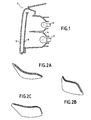
- a screen 6 which can be seen from different angles in FIGS. 2a to 2c.
- This screen is made of transparent plastic, PMMA (poly methyl methacrylate), with a thickness between 2 and 5 mm, in particular to facilitate its manufacture by molding by injection. Its color can be crystal (colorless), pink or smoke to remain compatible with the reversing and / or indicator functions of management.
- PMMA poly methyl methacrylate
- cavities and diode heads are preferably complementary, with sufficient play so that the diodes can be easily accommodated in the cavities.
- the screen is expected to bulge on this active periphery, coming to surround the cavities 9.
- the combination of cavities 9 and bulge (one bulge per cavity when there is several cavities, a continuous bulge when there is only one single cavity housing several diodes) allows to recover all or almost all the light energy of the diodes on a cone emissive which can reach 180 °.
- Figures 5a-5f show a third modification of the section of screen 6 in the “active” zones: the figure 5a represents seen from below the cavity 9, the bulge, but also a base 11, which is an approximately flat area perpendicular to the plane of the screen. This flat area 11 will allow to fix the support plate 12 of the diodes 7.
- the width of the base 11 coincides with that of the support plate 12.
- the diodes 7 are placed in the cavities 9.
- different mechanical solutions are possible, including gluing, screwing or even clipping.
- Figures 5d-5f show a third solution: the boutrollage:
- the bouterolles 13 are on the base (again, molded with the screen) in Figure 5d, they are overwritten in figure 5f in order to rivet the two parts one to the other, and block the diodes 7 in position.
- Figure 3 symbolizes two paths of two rays emitted by one of the diodes 7: we see that they travel in the thickness of screen 6 by successive reflections on the faces of the screen. As detailed in Figure 4, these successive reflections are interrupted when the rays meet foci of diffusion 10 created according to the invention on the surface of one of the faces of the screen these rays which are in the vicinity of the face thus modified (the grazing rays) will diffuse in all directions (symbolized by the arrows). These homes 10 are hollow diffusing patterns on the surface optical polish of the screen 6. Each focus 10 then behaves as a secondary optical source.
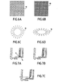
- Figures 6a to 6d thus give examples of distribution, these representations not being the scale to be clearer.
- the dimensions of these recesses are with an apparent surface of 0.1 to 1 or 2 mm, they have varying depths from a few hundredths of a millimeter to a millimeter, their shape can be scalable, especially from round to rectangular, their surface finish diffuses via structured micropatterns to optimize spatial diffusion isotropic, whatever the position of the observer following the vehicle. If, on the contrary, we want to create homes reflective, their surface finish will be rather polished optically.
- Their distribution can be homogeneous, regular or evolving according to a given direction ( Figure 6c or 6d).
- “Pixelation”, that is to say the mode of distribution of the households, can be organized according to a predefined or random screening.
- the distance between two homes is variable, for example between 1 mm and 10 to 20mm.
- the distribution can highlight an optical function primary ( Figure 6a or 6b).
- These homes 10 are obtained directly during the molding of the screen, by providing the mold appropriate reliefs.
- We can thus obtain a screen effect illuminated on part of its surface, or on its entire surface: the observer will see the whole surface of the fire lit, we get a trompe l'oeil which gives the impression of a fire in three dimensions highlighting the style of the vehicle: this keeps the signature of the fire, whether it is on or off
- Figures 7a-7c show the different ways of treating the “passive” edges of screen 6:
- Figure 7a shows the screen 6 whose edge is covered with a coating metallic / reflective 14 (edge vacuum metallization): the rays “go back” in the thickness of the screen.
- Figure 7b shows an identical result, obtained by a beveled edge according to two sides (shape that can be obtained during molding).
- the figure 7c shows a song bevelled on one side only: in this case, the ray leaves in a direction determined by the way whose song is beveled, here approximately perpendicular to the screen through the glass 5.
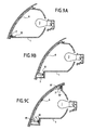
- Figure 8 shows a variant of providing the face of the screen already provided with diffusers of another type of hearth: reflective hearths 15. This or these reasons may be obtained as diffusing foci 10.
- the ray path striking these foci 15 is symbolized by the arrows: at least part of the rays (depending on their angle of incidence) goes go off the screen, in particular through the glass 5: this or these fireplaces can be arranged in a specific area for spatially focus the light (at the stop function for example).
- FIG. 9a illustrates three ways to deport the diodes 7 around the edge of the diffusing screen 6.
- the electronic card 12 supporting the diodes is fixed on the wall internal of the housing 1, in a substantially horizontal zone in mounting position in the vehicle, near the perimeter of screen 6. Said periphery is then modified, enlarged, if necessary, so that we can channel as before the light emitted by the diodes 7.
- FIG. 9b represents a another configuration, where the diode support 12 is fixed on a vertical wall of the case, with modification of the periphery of the screen to capture most of the light emitted by the diodes 7. This area of the periphery can be an integral part of the screen, or be reported on the screen.
- Figure 9c shows a configuration similar to that of figure 9b, but here the circumference of the screen at the bottom is not changed by a simple extension, a bending of its lower periphery: it here is to keep the standard lower edge of the screen, and add deflecting elements 17.
- the top of screen we also use a series of 7 'diodes on their support 12 'fixed to a vertical wall of the housing. Elements 17 'deflectors are also provided to collect the light emitted by these 7 'diodes.
- the deflecting elements 17 or 17 'either are either arranged side by side or constitute a protrusion continues along each of the edges of the screen.
- the "Appendages" constituted by these elements 17, 17 'or these extension of the periphery of the screen therefore collect the emitted flux by the diodes and ensures their spatial distribution in the thickness of the glass or screen.
- Diode supports are advantageously secured to the light boxes or projectors according to the invention.
- the invention therefore opens up new perspectives in terms style, while remaining feasible industrially.
- each screen may have its own distinct distribution / type of outbreaks diffusing and / or reflecting.
- the invention advantageously applies to signaling rear of vehicles or at the front signaling of vehicles, especially to realize at the front the function of city lamp.
- the modifications made by the invention to the ice or intermediate screens do not, of course, alter the functions usual photometric expected from fire or headlamp motor vehicles. Indeed, the entire screen or glass is transparent, polished, only the patterns can very slightly disturb the light beam emitted by the light source main light.
Priority Applications (3)
| Application Number | Priority Date | Filing Date | Title |
|---|---|---|---|
| EP15172775.7A EP2960572A1 (de) | 2002-12-20 | 2003-12-16 | Vorrichtung zur beleuchtung und/oder signalisierung vom typ scheinwerfer oder signalleuchte für kraftfahrzeuge |
| EP10195426.1A EP2302291B1 (de) | 2002-12-20 | 2003-12-16 | Beleuchtungs- und/oder Signalvorrichtung für Kraftfahrzeuge |
| EP10195418.8A EP2302290B1 (de) | 2002-12-20 | 2003-12-16 | Verfahren zur Herstellung von einem lichtstreuenden Schirm bzw. einer Schutzscheibe für eine Beleuchtungs- und/oder Signalvorrichtung für Kraftfahrzeuge |
Applications Claiming Priority (2)
| Application Number | Priority Date | Filing Date | Title |
|---|---|---|---|
| FR0216429 | 2002-12-20 | ||
| FR0216429A FR2849157B1 (fr) | 2002-12-20 | 2002-12-20 | Dispositif d'eclairage et/ou de signalisation du type projecteur ou feu pour vehicule automobile |
Related Child Applications (5)
| Application Number | Title | Priority Date | Filing Date |
|---|---|---|---|
| EP10195426.1A Division-Into EP2302291B1 (de) | 2002-12-20 | 2003-12-16 | Beleuchtungs- und/oder Signalvorrichtung für Kraftfahrzeuge |
| EP10195426.1A Division EP2302291B1 (de) | 2002-12-20 | 2003-12-16 | Beleuchtungs- und/oder Signalvorrichtung für Kraftfahrzeuge |
| EP15172775.7A Division EP2960572A1 (de) | 2002-12-20 | 2003-12-16 | Vorrichtung zur beleuchtung und/oder signalisierung vom typ scheinwerfer oder signalleuchte für kraftfahrzeuge |
| EP10195418.8A Division-Into EP2302290B1 (de) | 2002-12-20 | 2003-12-16 | Verfahren zur Herstellung von einem lichtstreuenden Schirm bzw. einer Schutzscheibe für eine Beleuchtungs- und/oder Signalvorrichtung für Kraftfahrzeuge |
| EP10195418.8A Division EP2302290B1 (de) | 2002-12-20 | 2003-12-16 | Verfahren zur Herstellung von einem lichtstreuenden Schirm bzw. einer Schutzscheibe für eine Beleuchtungs- und/oder Signalvorrichtung für Kraftfahrzeuge |
Publications (3)
| Publication Number | Publication Date |
|---|---|
| EP1434000A2 true EP1434000A2 (de) | 2004-06-30 |
| EP1434000A3 EP1434000A3 (de) | 2008-06-11 |
| EP1434000B1 EP1434000B1 (de) | 2015-07-15 |
Family
ID=32406329
Family Applications (4)
| Application Number | Title | Priority Date | Filing Date |
|---|---|---|---|
| EP10195426.1A Revoked EP2302291B1 (de) | 2002-12-20 | 2003-12-16 | Beleuchtungs- und/oder Signalvorrichtung für Kraftfahrzeuge |
| EP15172775.7A Ceased EP2960572A1 (de) | 2002-12-20 | 2003-12-16 | Vorrichtung zur beleuchtung und/oder signalisierung vom typ scheinwerfer oder signalleuchte für kraftfahrzeuge |
| EP10195418.8A Expired - Lifetime EP2302290B1 (de) | 2002-12-20 | 2003-12-16 | Verfahren zur Herstellung von einem lichtstreuenden Schirm bzw. einer Schutzscheibe für eine Beleuchtungs- und/oder Signalvorrichtung für Kraftfahrzeuge |
| EP03293164.4A Expired - Lifetime EP1434000B1 (de) | 2002-12-20 | 2003-12-16 | Beleuchtungs- und/oder Signalvorrichtung für Kraftfahrzeuge |
Family Applications Before (3)
| Application Number | Title | Priority Date | Filing Date |
|---|---|---|---|
| EP10195426.1A Revoked EP2302291B1 (de) | 2002-12-20 | 2003-12-16 | Beleuchtungs- und/oder Signalvorrichtung für Kraftfahrzeuge |
| EP15172775.7A Ceased EP2960572A1 (de) | 2002-12-20 | 2003-12-16 | Vorrichtung zur beleuchtung und/oder signalisierung vom typ scheinwerfer oder signalleuchte für kraftfahrzeuge |
| EP10195418.8A Expired - Lifetime EP2302290B1 (de) | 2002-12-20 | 2003-12-16 | Verfahren zur Herstellung von einem lichtstreuenden Schirm bzw. einer Schutzscheibe für eine Beleuchtungs- und/oder Signalvorrichtung für Kraftfahrzeuge |
Country Status (4)
| Country | Link |
|---|---|
| US (2) | US7111970B2 (de) |
| EP (4) | EP2302291B1 (de) |
| JP (1) | JP4606020B2 (de) |
| FR (1) | FR2849157B1 (de) |
Cited By (23)
| Publication number | Priority date | Publication date | Assignee | Title |
|---|---|---|---|---|
| FR2891891A1 (fr) | 2005-10-11 | 2007-04-13 | Valeo Vision Sa | Dispositif d'eclairage ou de signalisation a guide optique pour vehicule automobile |
| EP1898147A1 (de) * | 2006-09-11 | 2008-03-12 | Hella KG Hueck & Co. | Beleuchtungseinrichtung für Fahrzeuge |
| EP1978295A1 (de) | 2007-04-06 | 2008-10-08 | Valeo Vision | Leuchtsignalvorrichtung, die in der Lage ist, zwei Signalstrahlen gleicher Intensität und unterschiedlicher Leuchtdichte unabhängig voneinander abzugeben |
| EP1992868A1 (de) | 2007-05-15 | 2008-11-19 | Valeo Vision | Beleuchtungseinrichtung für Kraftfahrzeuge |
| EP2146138A1 (de) * | 2008-07-16 | 2010-01-20 | Odelo GmbH | Leuchte |
| WO2011070161A1 (fr) * | 2009-12-11 | 2011-06-16 | Automotive Lighting Rear Lamps France S.A.S. | Dispositif pour feu de signalisation de vehicule automobile |
| WO2011107352A1 (fr) | 2010-03-05 | 2011-09-09 | Valeo Vision | Dispositif d'éclairage et/ou de signalisation d'un véhicule automobile comprenant une source surfacique de lumière |
| WO2011113937A1 (fr) * | 2010-03-19 | 2011-09-22 | Automotive Lighting Rear Lamps France S.A.S. | Dispositif pour procurer un effet d'infini a un feu de signalisation de vehicule automobile |
| EP2453167A1 (de) | 2010-11-15 | 2012-05-16 | Valeo Vision | Vorrichtung zur Beleuchtung und/oder Signalisierung für Kraftfahrzeuge, die eine Oberflächenlichtquelle umfasst |
| EP2476947A2 (de) | 2011-01-14 | 2012-07-18 | Valeo Vision | Vorrichtung zur Beleuchtung oder Signalisierung mittels Lichtwellenleiter für Kraftfahrzeug |
| DE202013002220U1 (de) | 2012-03-07 | 2013-07-01 | Valeo Vision | Ablage einer Vorrichtung zum Beleuchten eines Bereichs eines Fahrgastraumes eines Fahrzeuges |
| EP2703220A1 (de) | 2012-08-29 | 2014-03-05 | Valeo Vision | Vorrichtung zur Beleuchtung und/oder Signalisierung für Kraftfahrzeug |
| EP2711610A1 (de) | 2012-09-25 | 2014-03-26 | Valeo Vision | Vorrichtung zur Beleuchtung und/oder Signalisierung, insbesondere für Kraftfahrzeuge |
| EP2711618A1 (de) | 2012-09-25 | 2014-03-26 | Valeo Vision | Beleuchtungsvorrichtung und/oder Signalvorrichtung für Fahrzeug |
| WO2014105408A3 (en) * | 2012-12-28 | 2014-10-09 | 3M Innovative Properties Company | Hybrid tailight article |
| WO2014105424A3 (en) * | 2012-12-28 | 2014-10-09 | 3M Innovative Properties Company | Stacked lightguide tailight article |
| EP3034931A2 (de) | 2014-12-19 | 2016-06-22 | Valeo Vision | Leuchtvorrichtung, die oberflächenlichtquellen umfasst |
| ITUA20162153A1 (it) * | 2016-03-31 | 2017-10-01 | Automotive Lighting Italia Spa | Fanale automobilistico |
| IT201600098165A1 (it) * | 2016-09-30 | 2018-03-30 | Automotive Lighting Italia Spa | Fanale automobilistico |
| WO2022128571A1 (fr) | 2020-12-18 | 2022-06-23 | Renault S.A.S | Projecteur pour vehicule avec une fonction d'eclairage situee derriere une fonction de signalisation |
| FR3120930A1 (fr) * | 2021-03-16 | 2022-09-23 | Psa Automobiles Sa | Bloc optique compact et assurant des fonctions photométriques d’éclairage et de signalisation, pour un véhicule |
| DE102021116888A1 (de) | 2021-06-30 | 2023-01-05 | Marelli Automotive Lighting Reutlingen (Germany) GmbH | Leuchte für ein Kraftfahrzeug mit einer Abdeckscheibe |
| FR3129122A1 (fr) | 2021-11-17 | 2023-05-19 | Valeo Vision | Module lumineux avec fonctions d’éclairage et de signalisation |
Families Citing this family (53)
| Publication number | Priority date | Publication date | Assignee | Title |
|---|---|---|---|---|
| FR2849157B1 (fr) * | 2002-12-20 | 2015-07-10 | Valeo Vision | Dispositif d'eclairage et/ou de signalisation du type projecteur ou feu pour vehicule automobile |
| DE102004056252A1 (de) * | 2004-10-29 | 2006-05-04 | Osram Opto Semiconductors Gmbh | Beleuchtungseinrichtung, Kfz-Scheinwerfer und Verfahren zur Herstellung einer Beleuchtungseinrichtung |
| US7828470B2 (en) * | 2005-01-24 | 2010-11-09 | Flextronics Automotive Inc. | Electronic indicator with backlighting |
| DE102005035066A1 (de) * | 2005-07-27 | 2007-02-01 | Hella Kgaa Hueck & Co. | Beleuchtungsvorrichtung für Kraftfahrzeuge |
| DE102006007134A1 (de) * | 2006-02-16 | 2007-08-23 | Hella Kgaa Hueck & Co. | Beleuchtungseinrichtung für Fahrzeuge |
| DE102006019287A1 (de) * | 2006-04-26 | 2007-10-31 | Bayerische Motoren Werke Ag | Kraftfahrzeugscheinwerfer |
| JP4678364B2 (ja) * | 2006-12-05 | 2011-04-27 | スタンレー電気株式会社 | 光源装置及び車両前照灯 |
| JP4842161B2 (ja) * | 2007-01-31 | 2011-12-21 | 株式会社小糸製作所 | 車両用灯具 |
| US20080259617A1 (en) * | 2007-04-19 | 2008-10-23 | Wayne M. Torcivia | Transportation system and method or methods for the restoration,re-manufacturing and re-conditioning or any combination thereof,of a vehicle headlight fixture or headlight fixture lens or any combination thereof |
| JP4979565B2 (ja) * | 2007-12-14 | 2012-07-18 | 株式会社小糸製作所 | 車両用灯具 |
| JP5152572B2 (ja) * | 2008-03-24 | 2013-02-27 | スタンレー電気株式会社 | 車両前照灯 |
| US8292480B2 (en) * | 2008-07-10 | 2012-10-23 | Koito Manufacturing Co., Ltd. | Lamp including main reflector, sub-reflector and LED assembly |
| US7828373B2 (en) * | 2008-09-24 | 2010-11-09 | Ford Global Technologies, Llc | Polycarbonate panel assembly for a vehicle |
| DE102008048751A1 (de) | 2008-09-25 | 2010-04-01 | Automotive Lighting Reutlingen Gmbh | Leuchte für Kraftfahrzeuge |
| JP5363235B2 (ja) * | 2009-08-04 | 2013-12-11 | 株式会社小糸製作所 | 車両用灯具 |
| DE102009053571B4 (de) | 2009-11-06 | 2017-11-09 | Automotive Lighting Reutlingen Gmbh | Leuchte für Kraftfahrzeuge mit einem Spiegelsystem und einem Lichtleiter |
| DE102010006974A1 (de) * | 2010-02-05 | 2011-08-11 | GM Global Technology Operations LLC, ( n. d. Ges. d. Staates Delaware ), Mich. | Beleuchtungseinrichtung für ein Fahrzeug |
| CN101922633A (zh) * | 2010-07-22 | 2010-12-22 | 鸿富锦精密工业(深圳)有限公司 | Led照明装置 |
| CN101922634A (zh) * | 2010-07-22 | 2010-12-22 | 鸿富锦精密工业(深圳)有限公司 | Led照明装置 |
| CN103153702A (zh) * | 2010-07-30 | 2013-06-12 | 汽车照明后灯法国有限公司 | 用于机动车辆的信号灯 |
| JP5575592B2 (ja) * | 2010-09-17 | 2014-08-20 | 株式会社小糸製作所 | 車両用灯具 |
| JP5675465B2 (ja) * | 2011-03-31 | 2015-02-25 | 株式会社小糸製作所 | 車両用灯具 |
| US9616807B2 (en) * | 2011-08-08 | 2017-04-11 | Fu-se Vacuum Forming CO., LTD. | Vehicle functional component |
| JP5779045B2 (ja) * | 2011-08-25 | 2015-09-16 | スタンレー電気株式会社 | 車両用灯具 |
| DE102012203929B3 (de) * | 2012-03-13 | 2013-09-19 | Automotive Lighting Reutlingen Gmbh | Lichtmodul einer Beleuchtungseinrichtung einesKraftfahrzeugs |
| DE102012206394A1 (de) * | 2012-04-18 | 2013-10-24 | Osram Gmbh | Leuchtvorrichtung mit Reflektor, Linse und Blende |
| DE102013223969B4 (de) | 2012-11-22 | 2015-03-26 | Automotive Lighting Reutlingen Gmbh | Flächiger Lichtleiter mit räumlich variierender Dicke |
| JP5529951B2 (ja) * | 2012-12-11 | 2014-06-25 | スタンレー電気株式会社 | フロントコンビネーション型灯具 |
| FR3011784B1 (fr) * | 2013-10-11 | 2017-04-21 | Valeo Vision Belgique | Dispositif d'eclairage ou de signalisation de vehicule automobile et procede d'assemblage correspondant |
| FR3017189B1 (fr) | 2014-02-04 | 2019-04-26 | Valeo Vision | Module d'eclairage et/ou de signalisation rotatif a source lumineuse fixe |
| DE102014104756A1 (de) * | 2014-04-03 | 2015-10-08 | Hella Kgaa Hueck & Co. | Beleuchtungsvorrichtung für Fahrzeuge |
| JP6636233B2 (ja) * | 2014-04-07 | 2020-01-29 | 株式会社小糸製作所 | 車両用灯具 |
| US9696015B2 (en) | 2014-07-23 | 2017-07-04 | Powerarc, Inc. | Changeable emergency warning light assembly |
| WO2016051491A1 (ja) * | 2014-09-30 | 2016-04-07 | 日立マクセル株式会社 | 車両用灯具 |
| DE102014116517B4 (de) * | 2014-11-12 | 2022-04-28 | Dr. Ing. H.C. F. Porsche Aktiengesellschaft | Beleuchtungseinrichtung |
| JP2016095996A (ja) * | 2014-11-14 | 2016-05-26 | スタンレー電気株式会社 | 車両用複合ランプ |
| US10408424B2 (en) * | 2015-01-19 | 2019-09-10 | SMR Patents S.à.r.l. | Light guiding device |
| KR102339518B1 (ko) * | 2015-02-25 | 2021-12-16 | 현대모비스 주식회사 | 자동차의 조명장치 |
| JP2016178031A (ja) * | 2015-03-20 | 2016-10-06 | トヨタ自動車株式会社 | 車両用灯具 |
| DE102015210372A1 (de) | 2015-06-05 | 2016-12-08 | Automotive Lighting Reutlingen Gmbh | Signallichtmodul für ein Kraftfahrzeug |
| JP6741467B2 (ja) * | 2016-05-12 | 2020-08-19 | 株式会社小糸製作所 | 車両用灯具 |
| JP7083830B2 (ja) * | 2016-12-23 | 2022-06-13 | ルミレッズ ホールディング ベーフェー | 自動車ヘッドライト用の導光板を有する発光モジュール |
| US10576877B2 (en) | 2017-03-24 | 2020-03-03 | Honda Patents & Technologies North America, Llc | Illuminated grille |
| DE102017117392A1 (de) * | 2017-08-01 | 2019-02-07 | HELLA GmbH & Co. KGaA | Beleuchtungsvorrichtung für Fahrzeuge |
| DE202017106281U1 (de) | 2017-10-17 | 2019-01-18 | Automotive Lighting Reutlingen Gmbh | Lichtleiter-Anordnung und Kraftfahrzeug-Beleuchtungseinrichtung mit einer solchen Lichtleiter-Anordnung |
| US10215360B1 (en) | 2018-05-18 | 2019-02-26 | Stanley Electric Co., Ltd. | Vehicle lighting device and method |
| EP3572719A1 (de) * | 2018-05-25 | 2019-11-27 | ZKW Group GmbH | Lichtmodul für einen kfz-scheinwerfer |
| DE102018113768A1 (de) * | 2018-06-08 | 2019-12-12 | Automotive Lighting Reutlingen Gmbh | Kraftfahrzeugscheinwerfer mit mindestens zwei Lichtmodulen |
| US11002420B2 (en) | 2018-12-21 | 2021-05-11 | Magna Exteriors Inc. | Vehicle headlamp having light guide |
| CN111856641A (zh) * | 2019-04-28 | 2020-10-30 | 法雷奥照明湖北技术中心有限公司 | 光导、包括该光导的发光装置以及机动车辆 |
| EP4043907A1 (de) | 2019-09-10 | 2022-08-17 | Koito Manufacturing Co., Ltd. | Leuchtenhalterung für fahrzeug, radarmodul, radar und fahrzeug |
| DE102019133693A1 (de) * | 2019-12-10 | 2021-06-10 | HELLA GmbH & Co. KGaA | Beleuchtungsvorrichtung für ein Kraftfahrzeug sowie Verfahren zur Herstellung einer derartigen Beleuchtungsvorrichtung |
| DE102021120001A1 (de) * | 2021-08-02 | 2023-02-02 | Dr. Ing. H.C. F. Porsche Aktiengesellschaft | Flächenlichtleiter für eine Leuchte eines Kraftfahrzeugs und Leuchte für ein Kraftfahrzeug |
Citations (3)
| Publication number | Priority date | Publication date | Assignee | Title |
|---|---|---|---|---|
| CH174197A (de) * | 1932-12-24 | 1934-12-31 | Bosch Robert Ag | Fahrzeugscheinwerfer. |
| FR2200806A5 (de) * | 1972-07-20 | 1974-04-19 | Cibie Projecteurs | |
| DE10101795A1 (de) * | 2001-01-17 | 2002-07-18 | Bosch Gmbh Robert | Blinkleuchte, insbesondere vordere Blinkleuchte, für Kraftfahrzeuge |
Family Cites Families (26)
| Publication number | Priority date | Publication date | Assignee | Title |
|---|---|---|---|---|
| FR2219651A6 (de) | 1972-07-20 | 1974-09-20 | Cibie Projecteurs | |
| GB1546805A (en) * | 1975-09-20 | 1979-05-31 | Lucas Industries Ltd | Method of manufacturing a mould for producing a lens element and mould manufactured by that method |
| JPS5445985A (en) * | 1977-09-19 | 1979-04-11 | Ichikoh Ind Ltd | Lighting apparatus for vehicles |
| JPS5943234U (ja) * | 1982-09-14 | 1984-03-21 | セントラル自動車株式会社 | ランプカバ− |
| JPS62167304U (de) | 1986-04-14 | 1987-10-23 | ||
| JPH0537362Y2 (de) * | 1988-02-29 | 1993-09-21 | ||
| DE4129094B4 (de) * | 1991-09-02 | 2005-08-25 | Hella Kgaa Hueck & Co. | Signalleuchte mit Leuchtdioden als Lichtquelle für Kraftfahrzeuge und deren Verwendung für unterschiedliche Signalleuchtenfunktionen |
| IT1261250B (it) * | 1993-09-03 | 1996-05-09 | Carello Spa | Dispositivo di illuminazione in particolare per autoveicoli |
| JPH07192510A (ja) * | 1993-12-24 | 1995-07-28 | Nissan Motor Co Ltd | 車両用灯具 |
| GB2288658B (en) * | 1994-04-19 | 1998-04-22 | Koito Mfg Co Ltd | Vehicular marker lamp lens compatible with two different kinds of light sources |
| JPH08169276A (ja) | 1994-12-19 | 1996-07-02 | Koito Mfg Co Ltd | 表示装置 |
| JP3330498B2 (ja) | 1996-07-01 | 2002-09-30 | 出光石油化学株式会社 | 導光板およびその製造方法 |
| JPH1153918A (ja) | 1997-08-01 | 1999-02-26 | Seiko Epson Corp | 照明装置および液晶表示装置および電子機器 |
| JPH11232906A (ja) * | 1998-02-17 | 1999-08-27 | Koito Mfg Co Ltd | 車両用灯具 |
| JP4212153B2 (ja) * | 1998-07-22 | 2009-01-21 | 日東樹脂工業株式会社 | 複合型光源装置 |
| US6352359B1 (en) * | 1998-08-25 | 2002-03-05 | Physical Optics Corporation | Vehicle light assembly including a diffuser surface structure |
| JP2000133011A (ja) * | 1998-10-20 | 2000-05-12 | Ichikoh Ind Ltd | 自動車用灯具 |
| JP2000251508A (ja) * | 1999-02-25 | 2000-09-14 | Stanley Electric Co Ltd | 車両用灯具 |
| FR2795672B1 (fr) * | 1999-06-29 | 2001-09-14 | Valeo Vision | Procede de moulage pour realiser une piece a structure multicouche |
| DE10022420B4 (de) * | 2000-05-09 | 2007-04-26 | Automotive Lighting Reutlingen Gmbh | Fahrzeugleuchte |
| JP2002025324A (ja) | 2000-07-03 | 2002-01-25 | Rohm Co Ltd | 照明装置および液晶表示装置 |
| DE10036324A1 (de) * | 2000-07-26 | 2002-02-07 | Hella Kg Hueck & Co | Mehrkammerleuchte für Fahrzeuge |
| JP2002100216A (ja) * | 2000-09-22 | 2002-04-05 | Ichikoh Ind Ltd | 車両用灯具 |
| FR2819040B1 (fr) | 2001-01-02 | 2003-09-12 | Valeo Vision | Composant d'optique ou de style pour dispositif d'eclairage ou de signalisation pour vehicule automobile |
| DE10207694A1 (de) | 2002-02-22 | 2003-11-13 | Hella Kg Hueck & Co | Lichteinheit für Fahrzeuge |
| FR2849157B1 (fr) * | 2002-12-20 | 2015-07-10 | Valeo Vision | Dispositif d'eclairage et/ou de signalisation du type projecteur ou feu pour vehicule automobile |
-
2002
- 2002-12-20 FR FR0216429A patent/FR2849157B1/fr not_active Expired - Fee Related
-
2003
- 2003-12-16 EP EP10195426.1A patent/EP2302291B1/de not_active Revoked
- 2003-12-16 EP EP15172775.7A patent/EP2960572A1/de not_active Ceased
- 2003-12-16 EP EP10195418.8A patent/EP2302290B1/de not_active Expired - Lifetime
- 2003-12-16 EP EP03293164.4A patent/EP1434000B1/de not_active Expired - Lifetime
- 2003-12-19 US US10/742,108 patent/US7111970B2/en not_active Expired - Lifetime
- 2003-12-22 JP JP2003424024A patent/JP4606020B2/ja not_active Expired - Lifetime
-
2006
- 2006-09-15 US US11/532,283 patent/US7278768B2/en not_active Expired - Lifetime
Patent Citations (3)
| Publication number | Priority date | Publication date | Assignee | Title |
|---|---|---|---|---|
| CH174197A (de) * | 1932-12-24 | 1934-12-31 | Bosch Robert Ag | Fahrzeugscheinwerfer. |
| FR2200806A5 (de) * | 1972-07-20 | 1974-04-19 | Cibie Projecteurs | |
| DE10101795A1 (de) * | 2001-01-17 | 2002-07-18 | Bosch Gmbh Robert | Blinkleuchte, insbesondere vordere Blinkleuchte, für Kraftfahrzeuge |
Cited By (38)
| Publication number | Priority date | Publication date | Assignee | Title |
|---|---|---|---|---|
| FR2891891A1 (fr) | 2005-10-11 | 2007-04-13 | Valeo Vision Sa | Dispositif d'eclairage ou de signalisation a guide optique pour vehicule automobile |
| EP1775511A1 (de) * | 2005-10-11 | 2007-04-18 | Valeo Vision | Kfz-Signal- und/oder Beleuchtungseinrichtung mit einem Lichtleiter |
| US7726854B2 (en) | 2005-10-11 | 2010-06-01 | Valeo Vision | Lighting or signal device with an optical guide for a motor vehicle |
| EP1898147A1 (de) * | 2006-09-11 | 2008-03-12 | Hella KG Hueck & Co. | Beleuchtungseinrichtung für Fahrzeuge |
| EP1978295A1 (de) | 2007-04-06 | 2008-10-08 | Valeo Vision | Leuchtsignalvorrichtung, die in der Lage ist, zwei Signalstrahlen gleicher Intensität und unterschiedlicher Leuchtdichte unabhängig voneinander abzugeben |
| FR2914731A1 (fr) | 2007-04-06 | 2008-10-10 | Valeo Vision Sa | Dispositif lumineux de signalisation susceptible d'emettre independamment deux faisceaux de signalisation de meme intensite et de luminances differentes |
| EP1992868A1 (de) | 2007-05-15 | 2008-11-19 | Valeo Vision | Beleuchtungseinrichtung für Kraftfahrzeuge |
| EP2146138A1 (de) * | 2008-07-16 | 2010-01-20 | Odelo GmbH | Leuchte |
| WO2011070161A1 (fr) * | 2009-12-11 | 2011-06-16 | Automotive Lighting Rear Lamps France S.A.S. | Dispositif pour feu de signalisation de vehicule automobile |
| FR2953781A1 (fr) * | 2009-12-11 | 2011-06-17 | Automotive Lighting Rear Lamps France | Dispositif pour feu de signalisation de vehicule automobile |
| US8939622B2 (en) | 2009-12-11 | 2015-01-27 | Automotive Lighting Rear Lamps France S.A.S. | Signal light device for a motor vehicle |
| WO2011107352A1 (fr) | 2010-03-05 | 2011-09-09 | Valeo Vision | Dispositif d'éclairage et/ou de signalisation d'un véhicule automobile comprenant une source surfacique de lumière |
| FR2957652A1 (fr) * | 2010-03-19 | 2011-09-23 | Automotive Lighting Rear Lamps France | Dispositif pour procurer un effet d'infini a un feu de signalisation de vehicule automobile |
| CN102939498A (zh) * | 2010-03-19 | 2013-02-20 | 汽车照明后灯法国有限公司 | 用于获得机动车信号灯的无限远效果的设备 |
| WO2011113937A1 (fr) * | 2010-03-19 | 2011-09-22 | Automotive Lighting Rear Lamps France S.A.S. | Dispositif pour procurer un effet d'infini a un feu de signalisation de vehicule automobile |
| US9121564B2 (en) | 2010-03-19 | 2015-09-01 | Automotive Lighting Rear Lamps France S.A.S. | Device for procuring an infinity effect for a motor vehicle signaling light |
| EP2453167A1 (de) | 2010-11-15 | 2012-05-16 | Valeo Vision | Vorrichtung zur Beleuchtung und/oder Signalisierung für Kraftfahrzeuge, die eine Oberflächenlichtquelle umfasst |
| EP2476947A2 (de) | 2011-01-14 | 2012-07-18 | Valeo Vision | Vorrichtung zur Beleuchtung oder Signalisierung mittels Lichtwellenleiter für Kraftfahrzeug |
| US8820991B2 (en) | 2011-01-14 | 2014-09-02 | Valeo Vision | Lighting or signalling device with optical guide for motor vehicles |
| DE202013002220U1 (de) | 2012-03-07 | 2013-07-01 | Valeo Vision | Ablage einer Vorrichtung zum Beleuchten eines Bereichs eines Fahrgastraumes eines Fahrzeuges |
| EP2703220A1 (de) | 2012-08-29 | 2014-03-05 | Valeo Vision | Vorrichtung zur Beleuchtung und/oder Signalisierung für Kraftfahrzeug |
| EP2711610A1 (de) | 2012-09-25 | 2014-03-26 | Valeo Vision | Vorrichtung zur Beleuchtung und/oder Signalisierung, insbesondere für Kraftfahrzeuge |
| EP2711618A1 (de) | 2012-09-25 | 2014-03-26 | Valeo Vision | Beleuchtungsvorrichtung und/oder Signalvorrichtung für Fahrzeug |
| WO2014105424A3 (en) * | 2012-12-28 | 2014-10-09 | 3M Innovative Properties Company | Stacked lightguide tailight article |
| WO2014105408A3 (en) * | 2012-12-28 | 2014-10-09 | 3M Innovative Properties Company | Hybrid tailight article |
| CN104903148A (zh) * | 2012-12-28 | 2015-09-09 | 3M创新有限公司 | 混合式尾灯制品 |
| EP3034931A2 (de) | 2014-12-19 | 2016-06-22 | Valeo Vision | Leuchtvorrichtung, die oberflächenlichtquellen umfasst |
| US10072811B2 (en) | 2014-12-19 | 2018-09-11 | Valeo Vision | Light device comprising surface light sources |
| ITUA20162153A1 (it) * | 2016-03-31 | 2017-10-01 | Automotive Lighting Italia Spa | Fanale automobilistico |
| EP3228928A1 (de) * | 2016-03-31 | 2017-10-11 | Automotive Lighting Italia S.p.A. | Beleuchtungseinheit für kraftfahrzeuge |
| EP3301352A1 (de) * | 2016-09-30 | 2018-04-04 | Automotive Lighting Italia S.p.A. | Fahrzeugleuchte |
| IT201600098165A1 (it) * | 2016-09-30 | 2018-03-30 | Automotive Lighting Italia Spa | Fanale automobilistico |
| WO2022128571A1 (fr) | 2020-12-18 | 2022-06-23 | Renault S.A.S | Projecteur pour vehicule avec une fonction d'eclairage situee derriere une fonction de signalisation |
| FR3117959A1 (fr) | 2020-12-18 | 2022-06-24 | Renault S.A.S | Projecteur pour vehicule avec une fonction d’eclairage situee derriere une fonction de signalisation |
| FR3120930A1 (fr) * | 2021-03-16 | 2022-09-23 | Psa Automobiles Sa | Bloc optique compact et assurant des fonctions photométriques d’éclairage et de signalisation, pour un véhicule |
| DE102021116888A1 (de) | 2021-06-30 | 2023-01-05 | Marelli Automotive Lighting Reutlingen (Germany) GmbH | Leuchte für ein Kraftfahrzeug mit einer Abdeckscheibe |
| FR3129122A1 (fr) | 2021-11-17 | 2023-05-19 | Valeo Vision | Module lumineux avec fonctions d’éclairage et de signalisation |
| WO2023088826A1 (fr) | 2021-11-17 | 2023-05-25 | Valeo Vision | Module lumineux avec fonctions d'éclairage et de signalisation |
Also Published As
| Publication number | Publication date |
|---|---|
| EP2302291A2 (de) | 2011-03-30 |
| US7278768B2 (en) | 2007-10-09 |
| FR2849157B1 (fr) | 2015-07-10 |
| EP1434000B1 (de) | 2015-07-15 |
| EP2302291B1 (de) | 2018-03-07 |
| EP2302290A2 (de) | 2011-03-30 |
| US20040136203A1 (en) | 2004-07-15 |
| EP2960572A1 (de) | 2015-12-30 |
| EP1434000A3 (de) | 2008-06-11 |
| US7111970B2 (en) | 2006-09-26 |
| US20070008736A1 (en) | 2007-01-11 |
| EP2302290B1 (de) | 2017-10-18 |
| JP4606020B2 (ja) | 2011-01-05 |
| JP2004207240A (ja) | 2004-07-22 |
| FR2849157A1 (fr) | 2004-06-25 |
| EP2302291A3 (de) | 2013-11-13 |
| EP2302290A3 (de) | 2013-10-16 |
Similar Documents
| Publication | Publication Date | Title |
|---|---|---|
| EP2302291B1 (de) | Beleuchtungs- und/oder Signalvorrichtung für Kraftfahrzeuge | |
| EP1288562B1 (de) | Beleuchtungs- oder Signalvorrichtung für Fahrzeug | |
| EP2317214B1 (de) | Vorrichtung zur Beleuchtung und/oder Signalisierung für Kraftfahrzeuge, die einen Lichtwellenleiter umfasst | |
| EP2476947B1 (de) | Vorrichtung zur Beleuchtung oder Signalisierung mittels Lichtwellenleiter für Kraftfahrzeug | |
| EP3390900B1 (de) | Lichteinheit, insbesondere für kfz-bremslicht | |
| EP3124854A1 (de) | Beleuchtungssystem für kraftfahrzeugscheinwerfer | |
| FR2934353A1 (fr) | Systeme optique avec fonction d'eclairage a large surface d'emission pour vehicule automobile | |
| EP1801492A1 (de) | Beleuchtungseinrichtung mit Lichtleitstab für Kraftfahrzeug | |
| FR3067443A1 (fr) | Dispositif d'eclairage pour vehicule, et hayon associe | |
| WO2011067515A1 (fr) | Dispositif d'éclairage à guide(s) de lumière intercalé(s) entre un réflecteur et un écran | |
| FR2916257A1 (fr) | Dispositif de signalisation ou d'eclairage pour vehicule automobile | |
| FR3015002A1 (fr) | Dispositif d'eclairage | |
| EP2999919B1 (de) | Optischer wellenleiter mit einem reflektierenden muster zur verbreitung eines lichtstrahls | |
| EP2926049B1 (de) | Fahrzeugsignalisierungsvorrichtung mit dreidimensionaler wirkung | |
| EP1489351B1 (de) | Fahrzeugscheinwerfer mit mindestens zwei Funktionen | |
| EP1496304B1 (de) | Signalleuchte für Fahrzeuge | |
| EP2712765B1 (de) | Beleuchtungsvorrichtung mit einem Lichtquellenmodul mit zwei Lichtausstrahlungsseiten | |
| FR2995061A1 (fr) | Dispositif lumineux, notamment d'eclairage et/ou de signalisation pour vehicule automobile | |
| WO2014020260A1 (fr) | Dispositif d'éclairage à guide(s) de lumière à face arrière à profil de conique et à éléments de diffusion définis sur une ligne de foyer | |
| FR2888182A1 (fr) | Dispositif d'eclairage interieur pour vehicule automobile | |
| FR3121501A1 (fr) | Ensemble guide de lumière pour un véhicule automobile | |
| FR2799266A1 (fr) | Procede de realisation d'un element dioptrique, et projecteur et element dioptrique d'eclairage | |
| EP1039215A1 (de) | Verbesserte Kraftfahrzeugleuchte mit mehreren Lichtquellen | |
| FR2911664A1 (fr) | Module d'eclairage ou de signalisation d'aspect ameliore |
Legal Events
| Date | Code | Title | Description |
|---|---|---|---|
| PUAI | Public reference made under article 153(3) epc to a published international application that has entered the european phase |
Free format text: ORIGINAL CODE: 0009012 |
|
| AK | Designated contracting states |
Kind code of ref document: A2 Designated state(s): AT BE BG CH CY CZ DE DK EE ES FI FR GB GR HU IE IT LI LU MC NL PT RO SE SI SK TR |
|
| AX | Request for extension of the european patent |
Extension state: AL LT LV MK |
|
| PUAL | Search report despatched |
Free format text: ORIGINAL CODE: 0009013 |
|
| AK | Designated contracting states |
Kind code of ref document: A3 Designated state(s): AT BE BG CH CY CZ DE DK EE ES FI FR GB GR HU IE IT LI LU MC NL PT RO SE SI SK TR |
|
| AX | Request for extension of the european patent |
Extension state: AL LT LV MK |
|
| 17P | Request for examination filed |
Effective date: 20081118 |
|
| AKX | Designation fees paid |
Designated state(s): AT BE BG CH CY CZ DE DK EE ES FI FR GB GR HU IE IT LI LU MC NL PT RO SE SI SK TR |
|
| 17Q | First examination report despatched |
Effective date: 20110311 |
|
| GRAP | Despatch of communication of intention to grant a patent |
Free format text: ORIGINAL CODE: EPIDOSNIGR1 |
|
| INTG | Intention to grant announced |
Effective date: 20150206 |
|
| GRAS | Grant fee paid |
Free format text: ORIGINAL CODE: EPIDOSNIGR3 |
|
| GRAA | (expected) grant |
Free format text: ORIGINAL CODE: 0009210 |
|
| AK | Designated contracting states |
Kind code of ref document: B1 Designated state(s): AT BE BG CH CY CZ DE DK EE ES FI FR GB GR HU IE IT LI LU MC NL PT RO SE SI SK TR |
|
| REG | Reference to a national code |
Ref country code: CH Ref legal event code: EP Ref country code: GB Ref legal event code: FG4D Free format text: NOT ENGLISH |
|
| REG | Reference to a national code |
Ref country code: IE Ref legal event code: FG4D Free format text: LANGUAGE OF EP DOCUMENT: FRENCH |
|
| REG | Reference to a national code |
Ref country code: AT Ref legal event code: REF Ref document number: 736982 Country of ref document: AT Kind code of ref document: T Effective date: 20150815 |
|
| REG | Reference to a national code |
Ref country code: DE Ref legal event code: R096 Ref document number: 60347817 Country of ref document: DE |
|
| REG | Reference to a national code |
Ref country code: AT Ref legal event code: MK05 Ref document number: 736982 Country of ref document: AT Kind code of ref document: T Effective date: 20150715 |
|
| REG | Reference to a national code |
Ref country code: NL Ref legal event code: MP Effective date: 20150715 |
|
| REG | Reference to a national code |
Ref country code: FR Ref legal event code: PLFP Year of fee payment: 13 |
|
| PG25 | Lapsed in a contracting state [announced via postgrant information from national office to epo] |
Ref country code: FI Free format text: LAPSE BECAUSE OF FAILURE TO SUBMIT A TRANSLATION OF THE DESCRIPTION OR TO PAY THE FEE WITHIN THE PRESCRIBED TIME-LIMIT Effective date: 20150715 Ref country code: GR Free format text: LAPSE BECAUSE OF FAILURE TO SUBMIT A TRANSLATION OF THE DESCRIPTION OR TO PAY THE FEE WITHIN THE PRESCRIBED TIME-LIMIT Effective date: 20151016 |
|
| PG25 | Lapsed in a contracting state [announced via postgrant information from national office to epo] |
Ref country code: SE Free format text: LAPSE BECAUSE OF FAILURE TO SUBMIT A TRANSLATION OF THE DESCRIPTION OR TO PAY THE FEE WITHIN THE PRESCRIBED TIME-LIMIT Effective date: 20150715 Ref country code: AT Free format text: LAPSE BECAUSE OF FAILURE TO SUBMIT A TRANSLATION OF THE DESCRIPTION OR TO PAY THE FEE WITHIN THE PRESCRIBED TIME-LIMIT Effective date: 20150715 Ref country code: ES Free format text: LAPSE BECAUSE OF FAILURE TO SUBMIT A TRANSLATION OF THE DESCRIPTION OR TO PAY THE FEE WITHIN THE PRESCRIBED TIME-LIMIT Effective date: 20150715 Ref country code: PT Free format text: LAPSE BECAUSE OF FAILURE TO SUBMIT A TRANSLATION OF THE DESCRIPTION OR TO PAY THE FEE WITHIN THE PRESCRIBED TIME-LIMIT Effective date: 20151116 |
|
| REG | Reference to a national code |
Ref country code: DE Ref legal event code: R097 Ref document number: 60347817 Country of ref document: DE |
|
| PG25 | Lapsed in a contracting state [announced via postgrant information from national office to epo] |
Ref country code: IT Free format text: LAPSE BECAUSE OF FAILURE TO SUBMIT A TRANSLATION OF THE DESCRIPTION OR TO PAY THE FEE WITHIN THE PRESCRIBED TIME-LIMIT Effective date: 20150715 Ref country code: CZ Free format text: LAPSE BECAUSE OF FAILURE TO SUBMIT A TRANSLATION OF THE DESCRIPTION OR TO PAY THE FEE WITHIN THE PRESCRIBED TIME-LIMIT Effective date: 20150715 Ref country code: EE Free format text: LAPSE BECAUSE OF FAILURE TO SUBMIT A TRANSLATION OF THE DESCRIPTION OR TO PAY THE FEE WITHIN THE PRESCRIBED TIME-LIMIT Effective date: 20150715 Ref country code: SK Free format text: LAPSE BECAUSE OF FAILURE TO SUBMIT A TRANSLATION OF THE DESCRIPTION OR TO PAY THE FEE WITHIN THE PRESCRIBED TIME-LIMIT Effective date: 20150715 Ref country code: DK Free format text: LAPSE BECAUSE OF FAILURE TO SUBMIT A TRANSLATION OF THE DESCRIPTION OR TO PAY THE FEE WITHIN THE PRESCRIBED TIME-LIMIT Effective date: 20150715 |
|
| PLBE | No opposition filed within time limit |
Free format text: ORIGINAL CODE: 0009261 |
|
| STAA | Information on the status of an ep patent application or granted ep patent |
Free format text: STATUS: NO OPPOSITION FILED WITHIN TIME LIMIT |
|
| PG25 | Lapsed in a contracting state [announced via postgrant information from national office to epo] |
Ref country code: BE Free format text: LAPSE BECAUSE OF NON-PAYMENT OF DUE FEES Effective date: 20151231 Ref country code: RO Free format text: LAPSE BECAUSE OF FAILURE TO SUBMIT A TRANSLATION OF THE DESCRIPTION OR TO PAY THE FEE WITHIN THE PRESCRIBED TIME-LIMIT Effective date: 20150715 |
|
| 26N | No opposition filed |
Effective date: 20160418 |
|
| PG25 | Lapsed in a contracting state [announced via postgrant information from national office to epo] |
Ref country code: LU Free format text: LAPSE BECAUSE OF FAILURE TO SUBMIT A TRANSLATION OF THE DESCRIPTION OR TO PAY THE FEE WITHIN THE PRESCRIBED TIME-LIMIT Effective date: 20151216 Ref country code: MC Free format text: LAPSE BECAUSE OF FAILURE TO SUBMIT A TRANSLATION OF THE DESCRIPTION OR TO PAY THE FEE WITHIN THE PRESCRIBED TIME-LIMIT Effective date: 20150715 |
|
| REG | Reference to a national code |
Ref country code: CH Ref legal event code: PL |
|
| GBPC | Gb: european patent ceased through non-payment of renewal fee |
Effective date: 20151216 |
|
| PG25 | Lapsed in a contracting state [announced via postgrant information from national office to epo] |
Ref country code: SI Free format text: LAPSE BECAUSE OF FAILURE TO SUBMIT A TRANSLATION OF THE DESCRIPTION OR TO PAY THE FEE WITHIN THE PRESCRIBED TIME-LIMIT Effective date: 20150715 |
|
| REG | Reference to a national code |
Ref country code: IE Ref legal event code: MM4A |
|
| PG25 | Lapsed in a contracting state [announced via postgrant information from national office to epo] |
Ref country code: IE Free format text: LAPSE BECAUSE OF NON-PAYMENT OF DUE FEES Effective date: 20151216 Ref country code: CH Free format text: LAPSE BECAUSE OF NON-PAYMENT OF DUE FEES Effective date: 20151231 Ref country code: LI Free format text: LAPSE BECAUSE OF NON-PAYMENT OF DUE FEES Effective date: 20151231 Ref country code: GB Free format text: LAPSE BECAUSE OF NON-PAYMENT OF DUE FEES Effective date: 20151216 |
|
| REG | Reference to a national code |
Ref country code: FR Ref legal event code: PLFP Year of fee payment: 14 |
|
| PG25 | Lapsed in a contracting state [announced via postgrant information from national office to epo] |
Ref country code: HU Free format text: LAPSE BECAUSE OF FAILURE TO SUBMIT A TRANSLATION OF THE DESCRIPTION OR TO PAY THE FEE WITHIN THE PRESCRIBED TIME-LIMIT; INVALID AB INITIO Effective date: 20031216 Ref country code: BG Free format text: LAPSE BECAUSE OF FAILURE TO SUBMIT A TRANSLATION OF THE DESCRIPTION OR TO PAY THE FEE WITHIN THE PRESCRIBED TIME-LIMIT Effective date: 20150715 |
|
| PG25 | Lapsed in a contracting state [announced via postgrant information from national office to epo] |
Ref country code: NL Free format text: LAPSE BECAUSE OF FAILURE TO SUBMIT A TRANSLATION OF THE DESCRIPTION OR TO PAY THE FEE WITHIN THE PRESCRIBED TIME-LIMIT Effective date: 20150715 Ref country code: CY Free format text: LAPSE BECAUSE OF FAILURE TO SUBMIT A TRANSLATION OF THE DESCRIPTION OR TO PAY THE FEE WITHIN THE PRESCRIBED TIME-LIMIT Effective date: 20150715 |
|
| PG25 | Lapsed in a contracting state [announced via postgrant information from national office to epo] |
Ref country code: TR Free format text: LAPSE BECAUSE OF FAILURE TO SUBMIT A TRANSLATION OF THE DESCRIPTION OR TO PAY THE FEE WITHIN THE PRESCRIBED TIME-LIMIT Effective date: 20150715 |
|
| REG | Reference to a national code |
Ref country code: DE Ref legal event code: R079 Ref document number: 60347817 Country of ref document: DE Free format text: PREVIOUS MAIN CLASS: F21S0008100000 Ipc: F21S0043000000 |
|
| REG | Reference to a national code |
Ref country code: FR Ref legal event code: PLFP Year of fee payment: 15 |
|
| PGFP | Annual fee paid to national office [announced via postgrant information from national office to epo] |
Ref country code: FR Payment date: 20221220 Year of fee payment: 20 Ref country code: DE Payment date: 20221209 Year of fee payment: 20 |
|
| P01 | Opt-out of the competence of the unified patent court (upc) registered |
Effective date: 20230528 |
|
| REG | Reference to a national code |
Ref country code: DE Ref legal event code: R071 Ref document number: 60347817 Country of ref document: DE |