EP1978295A1 - Leuchtsignalvorrichtung, die in der Lage ist, zwei Signalstrahlen gleicher Intensität und unterschiedlicher Leuchtdichte unabhängig voneinander abzugeben - Google Patents
Leuchtsignalvorrichtung, die in der Lage ist, zwei Signalstrahlen gleicher Intensität und unterschiedlicher Leuchtdichte unabhängig voneinander abzugeben Download PDFInfo
- Publication number
- EP1978295A1 EP1978295A1 EP08153784A EP08153784A EP1978295A1 EP 1978295 A1 EP1978295 A1 EP 1978295A1 EP 08153784 A EP08153784 A EP 08153784A EP 08153784 A EP08153784 A EP 08153784A EP 1978295 A1 EP1978295 A1 EP 1978295A1
- Authority
- EP
- European Patent Office
- Prior art keywords
- light
- intensity
- signaling
- optical module
- main
- Prior art date
- Legal status (The legal status is an assumption and is not a legal conclusion. Google has not performed a legal analysis and makes no representation as to the accuracy of the status listed.)
- Granted
Links
- 230000011664 signaling Effects 0.000 title claims abstract description 101
- 235000019557 luminance Nutrition 0.000 title 1
- 230000003287 optical effect Effects 0.000 claims abstract description 85
- 238000009792 diffusion process Methods 0.000 claims abstract description 27
- 238000000034 method Methods 0.000 claims abstract description 14
- 230000005540 biological transmission Effects 0.000 claims description 24
- 208000032370 Secondary transmission Diseases 0.000 claims description 16
- 230000009131 signaling function Effects 0.000 claims description 11
- 230000006870 function Effects 0.000 claims description 9
- 230000001902 propagating effect Effects 0.000 claims description 2
- XLYOFNOQVPJJNP-UHFFFAOYSA-N water Substances O XLYOFNOQVPJJNP-UHFFFAOYSA-N 0.000 description 3
- 230000004913 activation Effects 0.000 description 2
- 230000001276 controlling effect Effects 0.000 description 2
- 230000001105 regulatory effect Effects 0.000 description 2
- 239000012080 ambient air Substances 0.000 description 1
- 238000000149 argon plasma sintering Methods 0.000 description 1
- 230000002238 attenuated effect Effects 0.000 description 1
- 230000003247 decreasing effect Effects 0.000 description 1
- 239000011521 glass Substances 0.000 description 1
- 230000008447 perception Effects 0.000 description 1
- 229920003023 plastic Polymers 0.000 description 1
- 230000035807 sensation Effects 0.000 description 1
- 239000007921 spray Substances 0.000 description 1
- 239000012780 transparent material Substances 0.000 description 1
Images
Classifications
-
- B—PERFORMING OPERATIONS; TRANSPORTING
- B60—VEHICLES IN GENERAL
- B60Q—ARRANGEMENT OF SIGNALLING OR LIGHTING DEVICES, THE MOUNTING OR SUPPORTING THEREOF OR CIRCUITS THEREFOR, FOR VEHICLES IN GENERAL
- B60Q1/00—Arrangement of optical signalling or lighting devices, the mounting or supporting thereof or circuits therefor
- B60Q1/26—Arrangement of optical signalling or lighting devices, the mounting or supporting thereof or circuits therefor the devices being primarily intended to indicate the vehicle, or parts thereof, or to give signals, to other traffic
- B60Q1/2603—Attenuation of the light according to ambient luminiosity, e.g. for braking or direction indicating lamps
-
- B—PERFORMING OPERATIONS; TRANSPORTING
- B60—VEHICLES IN GENERAL
- B60Q—ARRANGEMENT OF SIGNALLING OR LIGHTING DEVICES, THE MOUNTING OR SUPPORTING THEREOF OR CIRCUITS THEREFOR, FOR VEHICLES IN GENERAL
- B60Q1/00—Arrangement of optical signalling or lighting devices, the mounting or supporting thereof or circuits therefor
- B60Q1/26—Arrangement of optical signalling or lighting devices, the mounting or supporting thereof or circuits therefor the devices being primarily intended to indicate the vehicle, or parts thereof, or to give signals, to other traffic
- B60Q1/2607—Arrangement of optical signalling or lighting devices, the mounting or supporting thereof or circuits therefor the devices being primarily intended to indicate the vehicle, or parts thereof, or to give signals, to other traffic comprising at least two indicating lamps
-
- F—MECHANICAL ENGINEERING; LIGHTING; HEATING; WEAPONS; BLASTING
- F21—LIGHTING
- F21S—NON-PORTABLE LIGHTING DEVICES; SYSTEMS THEREOF; VEHICLE LIGHTING DEVICES SPECIALLY ADAPTED FOR VEHICLE EXTERIORS
- F21S43/00—Signalling devices specially adapted for vehicle exteriors, e.g. brake lamps, direction indicator lights or reversing lights
- F21S43/20—Signalling devices specially adapted for vehicle exteriors, e.g. brake lamps, direction indicator lights or reversing lights characterised by refractors, transparent cover plates, light guides or filters
- F21S43/235—Light guides
- F21S43/236—Light guides characterised by the shape of the light guide
- F21S43/239—Light guides characterised by the shape of the light guide plate-shaped
-
- F—MECHANICAL ENGINEERING; LIGHTING; HEATING; WEAPONS; BLASTING
- F21—LIGHTING
- F21S—NON-PORTABLE LIGHTING DEVICES; SYSTEMS THEREOF; VEHICLE LIGHTING DEVICES SPECIALLY ADAPTED FOR VEHICLE EXTERIORS
- F21S43/00—Signalling devices specially adapted for vehicle exteriors, e.g. brake lamps, direction indicator lights or reversing lights
- F21S43/20—Signalling devices specially adapted for vehicle exteriors, e.g. brake lamps, direction indicator lights or reversing lights characterised by refractors, transparent cover plates, light guides or filters
- F21S43/235—Light guides
- F21S43/242—Light guides characterised by the emission area
- F21S43/243—Light guides characterised by the emission area emitting light from one or more of its extremities
-
- F—MECHANICAL ENGINEERING; LIGHTING; HEATING; WEAPONS; BLASTING
- F21—LIGHTING
- F21S—NON-PORTABLE LIGHTING DEVICES; SYSTEMS THEREOF; VEHICLE LIGHTING DEVICES SPECIALLY ADAPTED FOR VEHICLE EXTERIORS
- F21S43/00—Signalling devices specially adapted for vehicle exteriors, e.g. brake lamps, direction indicator lights or reversing lights
- F21S43/20—Signalling devices specially adapted for vehicle exteriors, e.g. brake lamps, direction indicator lights or reversing lights characterised by refractors, transparent cover plates, light guides or filters
- F21S43/235—Light guides
- F21S43/249—Light guides with two or more light sources being coupled into the light guide
-
- B—PERFORMING OPERATIONS; TRANSPORTING
- B60—VEHICLES IN GENERAL
- B60Q—ARRANGEMENT OF SIGNALLING OR LIGHTING DEVICES, THE MOUNTING OR SUPPORTING THEREOF OR CIRCUITS THEREFOR, FOR VEHICLES IN GENERAL
- B60Q2400/00—Special features or arrangements of exterior signal lamps for vehicles
- B60Q2400/20—Multi-color single source or LED matrix, e.g. yellow blinker and red brake lamp generated by single lamp
Definitions
- the invention relates to a luminous signaling device for a motor vehicle.
- the invention relates more particularly to a signaling light device for a motor vehicle which is intended to perform a first signaling function and which comprises a first optical module capable of transmitting homogeneously through a main transverse transmitting surface. a first intensity intensity signaling beam determined at a rear generally along a longitudinal optical axis.
- This type of signaling device is generally arranged at the rear of the motor vehicle, for example to form a "position lamp" whose function is to signal the presence and width of the motor vehicle to road users who are behind said vehicle.
- Such a signaling device has many advantages. In particular, it makes it possible to obtain a space-saving signaling device.
- these luminous signaling devices When they are activated, these luminous signaling devices are perfectly visible from a distance when the ambient luminosity is low, for example when it is dark or when the weather is very cloudy.
- the luminance of the main transmitting face of the signaling light device is lower than the luminance of the reflections on the vehicle. This gives an observer an impression that the signaling device is not activated.
- the luminance of a light device is defined by the ratio of the candela intensity (Cd) of a light source in a direction given by the area in square meter (m 2 ) of the apparent surface of the light source in the same direction.
- the unit of luminance is candela per square meter (Cd.m -2 ).
- the apparent surface is formed by the main transmission face.
- This maximum admitted intensity is generally too low to obtain a sufficient luminance for a signaling light device comprising a main transmission face having an extended area.
- This limitation of the intensity of the signal light therefore leads to a limitation of the area of the main emission face during the design of the signaling device.
- the present invention proposes a signaling device of the type described above, characterized in that the first optical module comprises a transverse light guiding ply which is delimited longitudinally by a diffusion front face having foci of light diffusion and by the main rear emission face, and a main light source which emits light rays substantially transversely to the light; interior of the guide ply by a singing edge of the light, the light rays propagating in the guide ply by successive total reflections between the diffusion and main emission faces, and in which the first light beam of signaling is formed by light rays diffused by the foci of diffusion in a substantially homogeneous manner through the main transmission face, in that it comprises a second optical module which emits a second light beam of signaling through a secondary transverse emission face along the longitudinal optical axis, the area of the secondary emission face being smaller than the area of the main transmitting face of the first optical module, and in that
- the invention also relates to a control method of such a device characterized in that the selection of the second optical module is controlled when the intensity of the ambient brightness is greater than a first predetermined threshold of intensity and / or when the contrast is less than a predetermined threshold of contrast.
- the term "intensity" will refer to a luminous intensity.
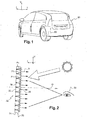
- figure 1 a motor vehicle at the rear of which are arranged two luminous signaling devices 20.
- These signaling light devices 20 are intended to carry out a first signaling function which is here a "position light” function intended to signal the position and the width of the vehicle to observers situated behind the vehicle.
- each signaling light device 20 is capable of emitting a first light beam "F1" signaling which is directed rearward globally in the overall direction of a longitudinal optical axis "O".
- the light signaling device 20 comprises a first optical module 22 comprising at least one main light source 24, and means 26 for diffusing the light emitted by the main light source 24 in a homogeneous manner through a main transverse surface 28 of emission to form the first signaling light beam "F1" optical axis "O" longitudinal.
- the first optical module 22 comprises a transverse vertical light-guiding sheet 30 which is formed by a plate of a transparent material having a refractive index. higher than that of the ambient air.
- the guide ply 30 shown in the figures is flat, but the invention is also applicable to curved guide plies.
- the guide ply 30 is thus delimited longitudinally by a first diffusion front face 32 and by the main transverse rear 28 transmission face.
- the longitudinal thickness of the guide ply 30 is substantially constant, and the front diffusion face 32 is parallel to the rear emission face.
- Both diffusion and transmit faces 28 have a polished and smooth appearance so that incident light rays having an angle of incidence greater than a limiting angle are specularly reflected.
- the guide ply 30 is delimited laterally by a contour formed of longitudinal edges 34.
- the light scattering means 26 are formed by a plurality of light diffusing foci 26 which are arranged in the diffusion front face 32.
- the diffusion foci 26 are here distributed homogeneously on the diffusion face 32 according to FIG. a regular mesh.
- the diffusion foci 26 are for example formed by irregularities of the diffusion face 32.
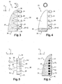
- the first optical module 22 shown in FIG. figure 3 comprises a plurality of main light sources 24 which will be called hereinafter "main light sources” 24 to distinguish them from the light source which will be associated with a second optical module as will be described later.
- the main light sources 24 are arranged to emit light rays substantially transversely inside the guide ply 30 by a singing edge 34 of the light.
- the main light sources 24 are formed by light-emitting diodes 24 which are aligned along the vertical vertical edge 34 of the guide ply 30.
- An associated light guide 35 is interposed between each main diode 24 and the edge 34 input to collimate the light rays emitted by each main diode 24 into an input light beam to give the incoming light rays directions favoring their propagation in the guide ply 30, that is to say that the light rays enter the guide ply 30 with an angle of incidence greater than a limit angle of refraction with respect to the faces 28, 32.
- Such a light guide 35 is described in more detail in the document EP-A1-1.746.339 .
- the light rays emitted by the main light sources 24 propagate in the guide ply 30 by successive total reflections between the diffusion face 32 and the main emission face 28 of the light.
- the light rays are thus captive inside the guide ply 30.
- the captive light rays which reach a diffusion focal point 26 are for the most part scattered with an angle of incidence less than the limit angle of refraction with respect to the main transmitting face 28 so that they pass through the main surface of the beam. light 28 to form the first signaling beam "F1" as shown in FIG. figure 2 .
- Each main light source 24 produces a portion of the first signaling light beam "F1" which passes through an associated portion of the main transmitting face. For example, as shown in figure 3 the light rays emitted by the main light source 24 arranged at the upper end of the input edge 34 are diffused by an upper end portion of the main transmission face 28.
- the light diffusion means are formed by a diffusion screen which transmits the light rays which reach it by diffusing them, the screen thus forming the main transmission face 28.
- the screen is for example a frosted plate of glass or transparent plastic.
- the screen is interposed in a signaling light beam emitted by a projector adapted to the signaling function to be performed.
- the standards require in particular that the intensity of the "F1" signaling beam emitted by the position rear lamp be within a prescribed prescribed range of values which is delimited by a maximum permitted intensity and a minimum permitted intensity.
- the experimental conditions for measuring the intensity of the signaling light beam "F1" are well known and are described in detail in the associated standards.
- the first signaling light beam "F1" has a determined intensity which is within the prescribed range.
- the determined intensity of the first signaling light beam "F1" is likely to vary within a range of use which is within the range prescribed by the standards and which is delimited by a minimum effective intensity and an effective maximum intensity. .
- the invention therefore proposes equipping the signaling light device 20 with a second optical module 38 which is capable of producing a second signaling light beam "F2" capable of fulfilling the same signaling function as the first signaling beam " F1 "and of the same intensity as the first signaling light beam” F1 ", but having a luminance sufficiently high to be perceptible by a human eye when the vehicle is exposed to high ambient light.
- the second optical module 38 comprises a secondary light source 42.
- the second optical module 38 can be activated independently of the first optical module 22 so that the optical module 22, 38 most suited to the ambient brightness is activated, as will be explained later.
- the invention proposes that the second signaling light beam "F2" be emitted by a secondary transmission face 40 which has an area smaller than the area of the main transmission face 28 of the first optical module 22 .
- a light beam of a given intensity that is emitted by a large apparent surface appears less bright to an observer 36 than a light beam of the same intensity that is emitted by a smaller apparent surface.
- the luminance of the second light beam "F2" is greater than that of the first light beam "F1".
- Figures 3 and 4 a first embodiment of the invention.
- the secondary light source 42 which produces the second signaling light beam "F2" is formed by an independent light-emitting diode 42 forming one of the main light sources 24.
- the independent diode 42 is arranged at a lower end of the edge 34.
- said independent diode 42 can be activated independently of the other main diodes 24 to form as the case may be one of the main light sources 24, or the secondary light source 42.
- the secondary transmission face 40 is thus formed by a portion of the main transmission face 28.
- the second signaling light beam "F2" is thus formed according to the same principle as the first light beam “F1", but using only a portion of the guide sheet 30.
- the luminous intensity of the second signaling light beam "F2" is increased.
- the first optical module 22 here comprises five main diodes 24 which have all the same power determined.
- the luminous power of the independent diode 42 is multiplied by at least five when it forms the secondary light source 42.
- the independent diode 42 is equipped with means (not shown) of light power variation which are known from the state of the art.
- the second optical module 38 comprises several secondary light sources 42 which are formed by a part of the diodes forming main light sources 24 of the first optical module 22.
- the luminance of the secondary transmission face 40 is higher than the luminance of the main transmission face 28.
- the perception of the second signaling light beam "F2" is also favored in contrast with the "dark" portions of the main transmission face 28 when only the second optical module 38 is activated.
- the secondary light source 42 is distinct from the main light source 24.
- the secondary light source 42 is arranged longitudinally forwardly and vis-à-vis the diffusion front face 32 of the guide ply 30 so as to form the second signaling light beam "F2" towards the rear according to FIG. optical axis "O".
- the second signaling light beam "F2" reaches the diffusion front face 32 with an angle less than the refractive limit angle. It therefore crosses the guide ply 30 without being reflected and exiting through a main transmission face portion 28, this portion forming the secondary transmission face 40.
- the secondary light sources 42 are here six in number, as shown in FIG. figure 6 .
- the secondary light sources 42 are for example formed by electroluminescent diodes whose light rays are collimated by a light guide 35 of the type described above to partly form the second light signaling beam "F2" directed rearwardly according to FIG. optical axis "O" longitudinal.
- Each secondary light source 42 forms a partial light beam which, in association with the other partial light beams, forms the second signaling light beam "F2".
- the sum of the intensities of the partial light beams is substantially equal to the determined intensity of the first signaling light beam "F1".
- each partial light beam passes through a circular portion of the main transmission face 28.
- the circular portions are disjointed. All of these circular portions form the secondary transmission face 40.
- the area of the secondary transmission face 40 is thus equal to the sum of the areas of said circular portions.
- Each partial light beam thus forms on the main emission face 28 a luminous point of high luminance which is perceptible by a human eye, even under conditions of high ambient light.
- the diffusion foci 26 of the guide ply 30 are of sufficiently negligible dimensions so that their influence is imperceptible on the partial light beam produced by each secondary light source 42.
- the second signaling light beam "F2" is formed by a conventional projector, comprising for example a filament lamp as a secondary light source 42, which is arranged longitudinally in front of the sheet. guide 30.
- the second optical module 38 has a secondary transmission face 40 which is distinct from the main transmission face 28.
- the second optical module 38 is for example formed by an independent projector which has an associated mirror forming the secondary surface of FIG. emission 40 so as to produce a second signaling light beam "F2" having a luminance greater than the luminance of the first optical module 22.
- the second optical module 38 made according to any one of the three previously described embodiments is capable of producing a second signaling function, for example a "stop light" function, by varying the intensity of the source. secondary light 42 beyond the maximum permitted intensity.
- a second signaling function for example a "stop light” function
- the photometric grid of a brake light is identical to that of a position light, with the difference that the brake light must emit a more intense light beam.
- the second optical module 38 capable of producing a second "F2" signaling light beam capable of perform the same signaling function as the first signaling beam "F1” and of the same intensity as the first signaling light beam "F1”, but having a luminance sufficiently high to be perceptible by a human eye when the vehicle is exposed to a high ambient brightness being constituted by a "stop light” under wattage, that is to say supplied with a lower electric power than its rated power, the second module optical 38 performing the second function of "brake light” regulatory when it is powered under nominal electrical power.
- ambient brightness is not the only factor that prevents an observer 36 from perceiving the glow of such a signaling light device 20.
- the invention proposes to arrange the secondary transmission face 40 of the second optical module 38 at an altitude at least equal to the altitude of an upper part of the main transmission face 28 with respect to the ground. .
- the second optical module 38 made according to the first embodiment, wherein the secondary transmission face 40 is arranged in an upper end portion of the main transmission face 28.
- the secondary transmission face 40 is located above the fog 44 so that the intensity of the second signaling light beam "F2" is not attenuated.
- the invention also relates to a control method of the signaling light device 20 produced according to the invention.
- the activation of the second optical module 38 is performed according to the ambient brightness.
- the signaling light device 20 is activated in response to signals provided by a sensor (not shown) for measuring the intensity of the ambient brightness.
- This sensor may be incorporated in the light signaling device 20. It may advantageously consist of the brightness sensor controlling the automatic ignition of the dipped beam, or consist of a camera.
- the selection of optical modules 22, 38 that can be activated is automatically controlled by an electronic control unit (not shown).
- the driver manually triggers the activation of the "position light” function, and the electronic control unit selects, according to the ambient brightness, the optical module 22, 38 which will be activated in response to manual triggering.
- the sensor is thus capable of emitting an electrical signal representative of the ambient brightness for the electronic control unit.
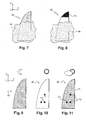
- the electronic control unit When the electronic control unit considers that the intensity of the ambient brightness is greater than a first predetermined intensity threshold, it controls the selection of the second optical module 38, as illustrated in FIG. figure 10 .
- the intensity of the second signaling light beam "F2" is slightly greater than the intensity of the first light beam "F1".
- the electronic control unit When the electronic control unit considers that the intensity of the ambient brightness is less than or equal to a second predetermined intensity threshold, it controls the selection of the first module 22, as illustrated in FIG. figure 9 .
- the first predetermined intensity threshold is equal to the second predetermined intensity threshold.
- only one of the two optical modules 22, 38 is capable of being activated.
- the first predetermined intensity threshold is lower than the second predetermined intensity threshold.
- the two optical modules 22, 38 are lit at the same time so that they can be perceived by all the observers 36, as shown in FIG. figure 11 .
- the luminous power of the main and secondary light sources 24 is controlled so that the sum the intensity of the first "F1" and second "F2" signaling light beams shall not be greater than the maximum intensity permitted by the standards in force.
- the invention has been described with reference to a signaling light device 20 arranged at the rear of the vehicle. It will be understood that this configuration is not limiting, and that the invention is also applicable to front or side traffic lights of the vehicle.
Applications Claiming Priority (1)
| Application Number | Priority Date | Filing Date | Title |
|---|---|---|---|
| FR0702579A FR2914731B1 (fr) | 2007-04-06 | 2007-04-06 | Dispositif lumineux de signalisation susceptible d'emettre independamment deux faisceaux de signalisation de meme intensite et de luminances differentes |
Publications (2)
| Publication Number | Publication Date |
|---|---|
| EP1978295A1 true EP1978295A1 (de) | 2008-10-08 |
| EP1978295B1 EP1978295B1 (de) | 2018-08-08 |
Family
ID=38542096
Family Applications (1)
| Application Number | Title | Priority Date | Filing Date |
|---|---|---|---|
| EP08153784.7A Active EP1978295B1 (de) | 2007-04-06 | 2008-03-31 | Leuchtsignalvorrichtung, die in der Lage ist, zwei Signalstrahlen gleicher Intensität und unterschiedlicher Leuchtdichte unabhängig voneinander abzugeben |
Country Status (2)
| Country | Link |
|---|---|
| EP (1) | EP1978295B1 (de) |
| FR (1) | FR2914731B1 (de) |
Cited By (5)
| Publication number | Priority date | Publication date | Assignee | Title |
|---|---|---|---|---|
| FR2988052A1 (fr) * | 2012-03-15 | 2013-09-20 | Valeo Systemes Dessuyage | Procede d'adaptation d'au moins un parametre photometrique d'une source lumineuse de vehicule automobile et systeme d'adaptation correspondant |
| CN107097729A (zh) * | 2016-02-23 | 2017-08-29 | 福特全球技术公司 | 车辆车标 |
| FR3051161A1 (fr) * | 2016-05-13 | 2017-11-17 | Peugeot Citroen Automobiles Sa | Dispositif de signalisation de bloc optique, a fonctions de signalisation controlees par une meme carte electronique |
| FR3054293A1 (fr) * | 2016-07-13 | 2018-01-26 | Valeo Vision | Dispositif d’eclairage et/ou de signalisation pour vehicule avec effet de lumiere defilante |
| EP3422706A1 (de) * | 2017-06-30 | 2019-01-02 | Valeo Vision | Leuchtsystem für kraftfahrzeug |
Citations (8)
| Publication number | Priority date | Publication date | Assignee | Title |
|---|---|---|---|---|
| DE19621148A1 (de) * | 1996-05-14 | 1997-12-04 | Magna Reflex Holding Gmbh | Leuchtelement |
| DE20008291U1 (de) * | 2000-05-09 | 2001-09-20 | Bosch Gmbh Robert | Heckleuchte für Kraftfahrzeuge für unterschiedliche Signalfunktionen |
| US20030012034A1 (en) * | 2001-07-16 | 2003-01-16 | Akihiro Misawa | Vehicle lamp |
| US20030086276A1 (en) * | 2001-11-02 | 2003-05-08 | Koito Manufacturing Co., Ltd. | Vehicle lamp |
| EP1434000A2 (de) | 2002-12-20 | 2004-06-30 | Valeo Vision | Beleuchtungs- und/oder Signalvorrichtung für Kraftfahrzeuge |
| DE102004025214A1 (de) * | 2004-05-22 | 2005-12-15 | Leonid Gaft | Rote hintere Bremsleuchte eines Kraftfahrzeuges |
| GB2418244A (en) * | 2004-09-18 | 2006-03-22 | Lear Corp | Multi intensity LED array with compensation for malfunction |
| EP1746339A1 (de) | 2005-07-21 | 2007-01-24 | Valeo Vision | Vorrichtung zur Beleuchtung oder Signalgebung, insbesondere für Fahrzeuge |
Family Cites Families (4)
| Publication number | Priority date | Publication date | Assignee | Title |
|---|---|---|---|---|
| DE4129094B4 (de) * | 1991-09-02 | 2005-08-25 | Hella Kgaa Hueck & Co. | Signalleuchte mit Leuchtdioden als Lichtquelle für Kraftfahrzeuge und deren Verwendung für unterschiedliche Signalleuchtenfunktionen |
| DE19919296A1 (de) * | 1999-04-28 | 2000-12-21 | Hella Kg Hueck & Co | Leuchte für Fahrzeuge |
| DE10022420B4 (de) * | 2000-05-09 | 2007-04-26 | Automotive Lighting Reutlingen Gmbh | Fahrzeugleuchte |
| DE102005021079B4 (de) * | 2005-05-06 | 2010-07-01 | Automotive Lighting Reutlingen Gmbh | Lichtleitelement mit Kraftfahrzeugleuchte |
-
2007
- 2007-04-06 FR FR0702579A patent/FR2914731B1/fr active Active
-
2008
- 2008-03-31 EP EP08153784.7A patent/EP1978295B1/de active Active
Patent Citations (8)
| Publication number | Priority date | Publication date | Assignee | Title |
|---|---|---|---|---|
| DE19621148A1 (de) * | 1996-05-14 | 1997-12-04 | Magna Reflex Holding Gmbh | Leuchtelement |
| DE20008291U1 (de) * | 2000-05-09 | 2001-09-20 | Bosch Gmbh Robert | Heckleuchte für Kraftfahrzeuge für unterschiedliche Signalfunktionen |
| US20030012034A1 (en) * | 2001-07-16 | 2003-01-16 | Akihiro Misawa | Vehicle lamp |
| US20030086276A1 (en) * | 2001-11-02 | 2003-05-08 | Koito Manufacturing Co., Ltd. | Vehicle lamp |
| EP1434000A2 (de) | 2002-12-20 | 2004-06-30 | Valeo Vision | Beleuchtungs- und/oder Signalvorrichtung für Kraftfahrzeuge |
| DE102004025214A1 (de) * | 2004-05-22 | 2005-12-15 | Leonid Gaft | Rote hintere Bremsleuchte eines Kraftfahrzeuges |
| GB2418244A (en) * | 2004-09-18 | 2006-03-22 | Lear Corp | Multi intensity LED array with compensation for malfunction |
| EP1746339A1 (de) | 2005-07-21 | 2007-01-24 | Valeo Vision | Vorrichtung zur Beleuchtung oder Signalgebung, insbesondere für Fahrzeuge |
Cited By (9)
| Publication number | Priority date | Publication date | Assignee | Title |
|---|---|---|---|---|
| FR2988052A1 (fr) * | 2012-03-15 | 2013-09-20 | Valeo Systemes Dessuyage | Procede d'adaptation d'au moins un parametre photometrique d'une source lumineuse de vehicule automobile et systeme d'adaptation correspondant |
| CN107097729A (zh) * | 2016-02-23 | 2017-08-29 | 福特全球技术公司 | 车辆车标 |
| FR3051161A1 (fr) * | 2016-05-13 | 2017-11-17 | Peugeot Citroen Automobiles Sa | Dispositif de signalisation de bloc optique, a fonctions de signalisation controlees par une meme carte electronique |
| FR3054293A1 (fr) * | 2016-07-13 | 2018-01-26 | Valeo Vision | Dispositif d’eclairage et/ou de signalisation pour vehicule avec effet de lumiere defilante |
| EP3422706A1 (de) * | 2017-06-30 | 2019-01-02 | Valeo Vision | Leuchtsystem für kraftfahrzeug |
| FR3068314A1 (fr) * | 2017-06-30 | 2019-01-04 | Valeo Vision | Systeme lumineux pour vehicule automobile |
| CN109204120A (zh) * | 2017-06-30 | 2019-01-15 | 法雷奥照明公司 | 用于机动车辆的灯光系统 |
| US10348975B2 (en) | 2017-06-30 | 2019-07-09 | Valeo Vision | Light system for a motor vehicle |
| CN109204120B (zh) * | 2017-06-30 | 2022-02-25 | 法雷奥照明公司 | 用于机动车辆的灯光系统 |
Also Published As
| Publication number | Publication date |
|---|---|
| FR2914731A1 (fr) | 2008-10-10 |
| FR2914731B1 (fr) | 2010-07-30 |
| EP1978295B1 (de) | 2018-08-08 |
Similar Documents
| Publication | Publication Date | Title |
|---|---|---|
| EP3071449B1 (de) | Beleuchtungs- und/oder signalisierungssystem mit lichtleitern für ein fahrzeug | |
| FR2828727A1 (fr) | Lampe de vehicule a diodes photoemissives | |
| EP2518392A2 (de) | Signalisierungsvorrichtung mit Stop- und Positionsfunktion, die einen Lichtwellenleiter benutzt und einen 3D-Effekt erzeugt | |
| EP1978295B1 (de) | Leuchtsignalvorrichtung, die in der Lage ist, zwei Signalstrahlen gleicher Intensität und unterschiedlicher Leuchtdichte unabhängig voneinander abzugeben | |
| FR2934353A1 (fr) | Systeme optique avec fonction d'eclairage a large surface d'emission pour vehicule automobile | |
| EP3002504A2 (de) | Leuchtmodul zur beleuchtung und/oder signalisierung für kraftfahrzeug | |
| EP2012056A1 (de) | Beleuchtungsvorrichtung zur Signalisation für Kraftfahrzeuge | |
| FR3030684B1 (fr) | Dispositif lumineux comprenant des sources surfaciques de lumiere | |
| EP1992868A1 (de) | Beleuchtungseinrichtung für Kraftfahrzeuge | |
| FR3035182A1 (fr) | Dispositif lumineux pour l'eclairage et/ou la signalisation d'un vehicule automobile | |
| WO2017025440A1 (fr) | Dispositif d'eclairage et/ou de signalisation pour vehicule automobile | |
| FR2858955A1 (fr) | Source de rayons infrarouges pour vehicules adaptee a un systeme de vision nocturne a infrarouge | |
| EP2991858A1 (de) | 3d-effekt-led-beleuchtungsvorrichtung mit streuungssystem | |
| FR3005717A1 (fr) | Dispositif d'eclairage a eclairement et couleur homogenes | |
| FR3010016A1 (fr) | Ensemble de climatisation de vehicule automobile | |
| EP3124856A1 (de) | Beleuchtungsvorrichtung für kraftfahrzeug | |
| EP3867563B1 (de) | Lichtmodul mit zwei fotometrischen funktionen mit unterschiedlichen lichtsignaturen | |
| WO2022207726A1 (fr) | Dispositif lumineux pour un véhicule automobile apte à créer un effet optique connu sous le nom de moiré | |
| EP3867565B1 (de) | Leuchtmodul mit zwei funktionen für eine optische beleuchtungs- und/oder signaleinheit eines fahrzeugs | |
| FR3075312A1 (fr) | Dispositif de signalisation lumineux pour vehicule automobile offrant un meilleur confort visuel pour les utilisateurs de la route | |
| FR2888182A1 (fr) | Dispositif d'eclairage interieur pour vehicule automobile | |
| EP3098501A1 (de) | Beleuchtungsvorrichtung für kraftfahrzeug | |
| FR2912806A1 (fr) | Feu de vehicule automobile. | |
| FR3137437A1 (fr) | Dispositif d’éclairage et de signalisation pour un véhicule automobile. | |
| EP4061672A1 (de) | Lichtmodul zum beleuchten eines fahrgastraums |
Legal Events
| Date | Code | Title | Description |
|---|---|---|---|
| PUAI | Public reference made under article 153(3) epc to a published international application that has entered the european phase |
Free format text: ORIGINAL CODE: 0009012 |
|
| AK | Designated contracting states |
Kind code of ref document: A1 Designated state(s): AT BE BG CH CY CZ DE DK EE ES FI FR GB GR HR HU IE IS IT LI LT LU LV MC MT NL NO PL PT RO SE SI SK TR |
|
| AX | Request for extension of the european patent |
Extension state: AL BA MK RS |
|
| 17P | Request for examination filed |
Effective date: 20090402 |
|
| AKX | Designation fees paid |
Designated state(s): AT BE BG CH CY CZ DE DK EE ES FI FR GB GR HR HU IE IS IT LI LT LU LV MC MT NL NO PL PT RO SE SI SK TR |
|
| 17Q | First examination report despatched |
Effective date: 20100208 |
|
| STAA | Information on the status of an ep patent application or granted ep patent |
Free format text: STATUS: EXAMINATION IS IN PROGRESS |
|
| REG | Reference to a national code |
Ref country code: DE Ref legal event code: R079 Ref document number: 602008056337 Country of ref document: DE Free format text: PREVIOUS MAIN CLASS: F21S0008100000 Ipc: B60Q0001260000 |
|
| GRAP | Despatch of communication of intention to grant a patent |
Free format text: ORIGINAL CODE: EPIDOSNIGR1 |
|
| STAA | Information on the status of an ep patent application or granted ep patent |
Free format text: STATUS: GRANT OF PATENT IS INTENDED |
|
| RIC1 | Information provided on ipc code assigned before grant |
Ipc: B60Q 1/26 20060101AFI20180219BHEP |
|
| INTG | Intention to grant announced |
Effective date: 20180316 |
|
| GRAS | Grant fee paid |
Free format text: ORIGINAL CODE: EPIDOSNIGR3 |
|
| GRAA | (expected) grant |
Free format text: ORIGINAL CODE: 0009210 |
|
| STAA | Information on the status of an ep patent application or granted ep patent |
Free format text: STATUS: THE PATENT HAS BEEN GRANTED |
|
| AK | Designated contracting states |
Kind code of ref document: B1 Designated state(s): AT BE BG CH CY CZ DE DK EE ES FI FR GB GR HR HU IE IS IT LI LT LU LV MC MT NL NO PL PT RO SE SI SK TR |
|
| REG | Reference to a national code |
Ref country code: GB Ref legal event code: FG4D Free format text: NOT ENGLISH |
|
| REG | Reference to a national code |
Ref country code: CH Ref legal event code: EP Ref country code: AT Ref legal event code: REF Ref document number: 1026612 Country of ref document: AT Kind code of ref document: T Effective date: 20180815 |
|
| REG | Reference to a national code |
Ref country code: IE Ref legal event code: FG4D Free format text: LANGUAGE OF EP DOCUMENT: FRENCH |
|
| REG | Reference to a national code |
Ref country code: DE Ref legal event code: R096 Ref document number: 602008056337 Country of ref document: DE |
|
| REG | Reference to a national code |
Ref country code: NL Ref legal event code: MP Effective date: 20180808 |
|
| REG | Reference to a national code |
Ref country code: LT Ref legal event code: MG4D |
|
| REG | Reference to a national code |
Ref country code: AT Ref legal event code: MK05 Ref document number: 1026612 Country of ref document: AT Kind code of ref document: T Effective date: 20180808 |
|
| PG25 | Lapsed in a contracting state [announced via postgrant information from national office to epo] |
Ref country code: IS Free format text: LAPSE BECAUSE OF FAILURE TO SUBMIT A TRANSLATION OF THE DESCRIPTION OR TO PAY THE FEE WITHIN THE PRESCRIBED TIME-LIMIT Effective date: 20181208 Ref country code: LT Free format text: LAPSE BECAUSE OF FAILURE TO SUBMIT A TRANSLATION OF THE DESCRIPTION OR TO PAY THE FEE WITHIN THE PRESCRIBED TIME-LIMIT Effective date: 20180808 Ref country code: PL Free format text: LAPSE BECAUSE OF FAILURE TO SUBMIT A TRANSLATION OF THE DESCRIPTION OR TO PAY THE FEE WITHIN THE PRESCRIBED TIME-LIMIT Effective date: 20180808 Ref country code: NO Free format text: LAPSE BECAUSE OF FAILURE TO SUBMIT A TRANSLATION OF THE DESCRIPTION OR TO PAY THE FEE WITHIN THE PRESCRIBED TIME-LIMIT Effective date: 20181108 Ref country code: AT Free format text: LAPSE BECAUSE OF FAILURE TO SUBMIT A TRANSLATION OF THE DESCRIPTION OR TO PAY THE FEE WITHIN THE PRESCRIBED TIME-LIMIT Effective date: 20180808 Ref country code: BG Free format text: LAPSE BECAUSE OF FAILURE TO SUBMIT A TRANSLATION OF THE DESCRIPTION OR TO PAY THE FEE WITHIN THE PRESCRIBED TIME-LIMIT Effective date: 20181108 Ref country code: NL Free format text: LAPSE BECAUSE OF FAILURE TO SUBMIT A TRANSLATION OF THE DESCRIPTION OR TO PAY THE FEE WITHIN THE PRESCRIBED TIME-LIMIT Effective date: 20180808 Ref country code: FI Free format text: LAPSE BECAUSE OF FAILURE TO SUBMIT A TRANSLATION OF THE DESCRIPTION OR TO PAY THE FEE WITHIN THE PRESCRIBED TIME-LIMIT Effective date: 20180808 Ref country code: GR Free format text: LAPSE BECAUSE OF FAILURE TO SUBMIT A TRANSLATION OF THE DESCRIPTION OR TO PAY THE FEE WITHIN THE PRESCRIBED TIME-LIMIT Effective date: 20181109 Ref country code: SE Free format text: LAPSE BECAUSE OF FAILURE TO SUBMIT A TRANSLATION OF THE DESCRIPTION OR TO PAY THE FEE WITHIN THE PRESCRIBED TIME-LIMIT Effective date: 20180808 |
|
| PG25 | Lapsed in a contracting state [announced via postgrant information from national office to epo] |
Ref country code: ES Free format text: LAPSE BECAUSE OF FAILURE TO SUBMIT A TRANSLATION OF THE DESCRIPTION OR TO PAY THE FEE WITHIN THE PRESCRIBED TIME-LIMIT Effective date: 20180808 Ref country code: LV Free format text: LAPSE BECAUSE OF FAILURE TO SUBMIT A TRANSLATION OF THE DESCRIPTION OR TO PAY THE FEE WITHIN THE PRESCRIBED TIME-LIMIT Effective date: 20180808 Ref country code: HR Free format text: LAPSE BECAUSE OF FAILURE TO SUBMIT A TRANSLATION OF THE DESCRIPTION OR TO PAY THE FEE WITHIN THE PRESCRIBED TIME-LIMIT Effective date: 20180808 |
|
| PG25 | Lapsed in a contracting state [announced via postgrant information from national office to epo] |
Ref country code: RO Free format text: LAPSE BECAUSE OF FAILURE TO SUBMIT A TRANSLATION OF THE DESCRIPTION OR TO PAY THE FEE WITHIN THE PRESCRIBED TIME-LIMIT Effective date: 20180808 Ref country code: IT Free format text: LAPSE BECAUSE OF FAILURE TO SUBMIT A TRANSLATION OF THE DESCRIPTION OR TO PAY THE FEE WITHIN THE PRESCRIBED TIME-LIMIT Effective date: 20180808 Ref country code: EE Free format text: LAPSE BECAUSE OF FAILURE TO SUBMIT A TRANSLATION OF THE DESCRIPTION OR TO PAY THE FEE WITHIN THE PRESCRIBED TIME-LIMIT Effective date: 20180808 Ref country code: CZ Free format text: LAPSE BECAUSE OF FAILURE TO SUBMIT A TRANSLATION OF THE DESCRIPTION OR TO PAY THE FEE WITHIN THE PRESCRIBED TIME-LIMIT Effective date: 20180808 |
|
| REG | Reference to a national code |
Ref country code: DE Ref legal event code: R097 Ref document number: 602008056337 Country of ref document: DE |
|
| PG25 | Lapsed in a contracting state [announced via postgrant information from national office to epo] |
Ref country code: DK Free format text: LAPSE BECAUSE OF FAILURE TO SUBMIT A TRANSLATION OF THE DESCRIPTION OR TO PAY THE FEE WITHIN THE PRESCRIBED TIME-LIMIT Effective date: 20180808 Ref country code: SK Free format text: LAPSE BECAUSE OF FAILURE TO SUBMIT A TRANSLATION OF THE DESCRIPTION OR TO PAY THE FEE WITHIN THE PRESCRIBED TIME-LIMIT Effective date: 20180808 |
|
| PLBE | No opposition filed within time limit |
Free format text: ORIGINAL CODE: 0009261 |
|
| STAA | Information on the status of an ep patent application or granted ep patent |
Free format text: STATUS: NO OPPOSITION FILED WITHIN TIME LIMIT |
|
| 26N | No opposition filed |
Effective date: 20190509 |
|
| PG25 | Lapsed in a contracting state [announced via postgrant information from national office to epo] |
Ref country code: SI Free format text: LAPSE BECAUSE OF FAILURE TO SUBMIT A TRANSLATION OF THE DESCRIPTION OR TO PAY THE FEE WITHIN THE PRESCRIBED TIME-LIMIT Effective date: 20180808 |
|
| PG25 | Lapsed in a contracting state [announced via postgrant information from national office to epo] |
Ref country code: MC Free format text: LAPSE BECAUSE OF FAILURE TO SUBMIT A TRANSLATION OF THE DESCRIPTION OR TO PAY THE FEE WITHIN THE PRESCRIBED TIME-LIMIT Effective date: 20180808 |
|
| REG | Reference to a national code |
Ref country code: CH Ref legal event code: PL |
|
| GBPC | Gb: european patent ceased through non-payment of renewal fee |
Effective date: 20190331 |
|
| PG25 | Lapsed in a contracting state [announced via postgrant information from national office to epo] |
Ref country code: LU Free format text: LAPSE BECAUSE OF NON-PAYMENT OF DUE FEES Effective date: 20190331 |
|
| REG | Reference to a national code |
Ref country code: BE Ref legal event code: MM Effective date: 20190331 |
|
| PG25 | Lapsed in a contracting state [announced via postgrant information from national office to epo] |
Ref country code: IE Free format text: LAPSE BECAUSE OF NON-PAYMENT OF DUE FEES Effective date: 20190331 Ref country code: GB Free format text: LAPSE BECAUSE OF NON-PAYMENT OF DUE FEES Effective date: 20190331 Ref country code: LI Free format text: LAPSE BECAUSE OF NON-PAYMENT OF DUE FEES Effective date: 20190331 Ref country code: CH Free format text: LAPSE BECAUSE OF NON-PAYMENT OF DUE FEES Effective date: 20190331 |
|
| PG25 | Lapsed in a contracting state [announced via postgrant information from national office to epo] |
Ref country code: BE Free format text: LAPSE BECAUSE OF NON-PAYMENT OF DUE FEES Effective date: 20190331 |
|
| PG25 | Lapsed in a contracting state [announced via postgrant information from national office to epo] |
Ref country code: TR Free format text: LAPSE BECAUSE OF FAILURE TO SUBMIT A TRANSLATION OF THE DESCRIPTION OR TO PAY THE FEE WITHIN THE PRESCRIBED TIME-LIMIT Effective date: 20180808 |
|
| PG25 | Lapsed in a contracting state [announced via postgrant information from national office to epo] |
Ref country code: PT Free format text: LAPSE BECAUSE OF FAILURE TO SUBMIT A TRANSLATION OF THE DESCRIPTION OR TO PAY THE FEE WITHIN THE PRESCRIBED TIME-LIMIT Effective date: 20181208 Ref country code: MT Free format text: LAPSE BECAUSE OF FAILURE TO SUBMIT A TRANSLATION OF THE DESCRIPTION OR TO PAY THE FEE WITHIN THE PRESCRIBED TIME-LIMIT Effective date: 20180808 |
|
| PG25 | Lapsed in a contracting state [announced via postgrant information from national office to epo] |
Ref country code: CY Free format text: LAPSE BECAUSE OF FAILURE TO SUBMIT A TRANSLATION OF THE DESCRIPTION OR TO PAY THE FEE WITHIN THE PRESCRIBED TIME-LIMIT Effective date: 20180808 |
|
| PG25 | Lapsed in a contracting state [announced via postgrant information from national office to epo] |
Ref country code: HU Free format text: LAPSE BECAUSE OF FAILURE TO SUBMIT A TRANSLATION OF THE DESCRIPTION OR TO PAY THE FEE WITHIN THE PRESCRIBED TIME-LIMIT; INVALID AB INITIO Effective date: 20080331 |
|
| PGFP | Annual fee paid to national office [announced via postgrant information from national office to epo] |
Ref country code: FR Payment date: 20230320 Year of fee payment: 16 |
|
| P01 | Opt-out of the competence of the unified patent court (upc) registered |
Effective date: 20230528 |
|
| PGFP | Annual fee paid to national office [announced via postgrant information from national office to epo] |
Ref country code: DE Payment date: 20240307 Year of fee payment: 17 |