EP1432934B1 - Emetteur de signaux concu pour regler les etats de fonctionnement d'un dispositif de commutation automatique - Google Patents
Emetteur de signaux concu pour regler les etats de fonctionnement d'un dispositif de commutation automatique Download PDFInfo
- Publication number
- EP1432934B1 EP1432934B1 EP02776737A EP02776737A EP1432934B1 EP 1432934 B1 EP1432934 B1 EP 1432934B1 EP 02776737 A EP02776737 A EP 02776737A EP 02776737 A EP02776737 A EP 02776737A EP 1432934 B1 EP1432934 B1 EP 1432934B1
- Authority
- EP
- European Patent Office
- Prior art keywords
- shift position
- deflected
- selection means
- starting
- signal transmitter
- Prior art date
- Legal status (The legal status is an assumption and is not a legal conclusion. Google has not performed a legal analysis and makes no representation as to the accuracy of the status listed.)
- Expired - Lifetime
Links
Images


Classifications
-
- F—MECHANICAL ENGINEERING; LIGHTING; HEATING; WEAPONS; BLASTING
- F16—ENGINEERING ELEMENTS AND UNITS; GENERAL MEASURES FOR PRODUCING AND MAINTAINING EFFECTIVE FUNCTIONING OF MACHINES OR INSTALLATIONS; THERMAL INSULATION IN GENERAL
- F16H—GEARING
- F16H59/00—Control inputs to control units of change-speed-, or reversing-gearings for conveying rotary motion
- F16H59/02—Selector apparatus
- F16H59/0204—Selector apparatus for automatic transmissions with means for range selection and manual shifting, e.g. range selector with tiptronic
-
- B—PERFORMING OPERATIONS; TRANSPORTING
- B60—VEHICLES IN GENERAL
- B60K—ARRANGEMENT OR MOUNTING OF PROPULSION UNITS OR OF TRANSMISSIONS IN VEHICLES; ARRANGEMENT OR MOUNTING OF PLURAL DIVERSE PRIME-MOVERS IN VEHICLES; AUXILIARY DRIVES FOR VEHICLES; INSTRUMENTATION OR DASHBOARDS FOR VEHICLES; ARRANGEMENTS IN CONNECTION WITH COOLING, AIR INTAKE, GAS EXHAUST OR FUEL SUPPLY OF PROPULSION UNITS IN VEHICLES
- B60K20/00—Arrangement or mounting of change-speed gearing control devices in vehicles
- B60K20/02—Arrangement or mounting of change-speed gearing control devices in vehicles of initiating means
- B60K20/06—Arrangement or mounting of change-speed gearing control devices in vehicles of initiating means mounted on steering column or the like
-
- Y—GENERAL TAGGING OF NEW TECHNOLOGICAL DEVELOPMENTS; GENERAL TAGGING OF CROSS-SECTIONAL TECHNOLOGIES SPANNING OVER SEVERAL SECTIONS OF THE IPC; TECHNICAL SUBJECTS COVERED BY FORMER USPC CROSS-REFERENCE ART COLLECTIONS [XRACs] AND DIGESTS
- Y10—TECHNICAL SUBJECTS COVERED BY FORMER USPC
- Y10T—TECHNICAL SUBJECTS COVERED BY FORMER US CLASSIFICATION
- Y10T74/00—Machine element or mechanism
- Y10T74/19—Gearing
- Y10T74/19219—Interchangeably locked
- Y10T74/19251—Control mechanism
-
- Y—GENERAL TAGGING OF NEW TECHNOLOGICAL DEVELOPMENTS; GENERAL TAGGING OF CROSS-SECTIONAL TECHNOLOGIES SPANNING OVER SEVERAL SECTIONS OF THE IPC; TECHNICAL SUBJECTS COVERED BY FORMER USPC CROSS-REFERENCE ART COLLECTIONS [XRACs] AND DIGESTS
- Y10—TECHNICAL SUBJECTS COVERED BY FORMER USPC
- Y10T—TECHNICAL SUBJECTS COVERED BY FORMER US CLASSIFICATION
- Y10T74/00—Machine element or mechanism
- Y10T74/20—Control lever and linkage systems
- Y10T74/20012—Multiple controlled elements
- Y10T74/20018—Transmission control
- Y10T74/20067—Control convertible between automatic and manual operation
-
- Y—GENERAL TAGGING OF NEW TECHNOLOGICAL DEVELOPMENTS; GENERAL TAGGING OF CROSS-SECTIONAL TECHNOLOGIES SPANNING OVER SEVERAL SECTIONS OF THE IPC; TECHNICAL SUBJECTS COVERED BY FORMER USPC CROSS-REFERENCE ART COLLECTIONS [XRACs] AND DIGESTS
- Y10—TECHNICAL SUBJECTS COVERED BY FORMER USPC
- Y10T—TECHNICAL SUBJECTS COVERED BY FORMER US CLASSIFICATION
- Y10T74/00—Machine element or mechanism
- Y10T74/20—Control lever and linkage systems
- Y10T74/20012—Multiple controlled elements
- Y10T74/20018—Transmission control
- Y10T74/2014—Manually operated selector [e.g., remotely controlled device, lever, push button, rotary dial, etc.]
- Y10T74/20159—Control lever movable through plural planes
- Y10T74/20165—Spherical mount [e.g., ball and socket]
- Y10T74/20171—Resiliently biased control lever
Definitions
- the present invention relates to a signal generator for setting the operating states of an automatic switching device of a gear change transmission with a selector device that at least for certain switching positions automatically returns to a basic position.
- Such switching devices usually have an operating state R for the engagement of the at least one reverse gear, an operating state N for the interruption of the torque transmission in the gear change transmission and an operating state D for the engagement of a forward gear.
- an operating state P is additionally provided for inserting a parking brake.
- the automatic shifting device of the gear change transmission selects from the available forward gears as a function of certain vehicle parameters, such as vehicle speed. B. the current speed or acceleration automatically according to one or more predetermined switching programs from the most appropriate appearing forward gear and controls the gear change accordingly.
- vehicle speed such as vehicle speed
- the driver of the vehicle can select his own shift programs for summer and winter and / or sporty driving and economical driving.
- switching devices are controlled via signal generator. Whereas control by the signal generator used to be effected mechanically by means of cables, electronic transmission of the signals is preferred today, since this allows a more flexible arrangement of the signal generator.
- such a signal generator has a switching lever usually provided on a center console of the vehicle.
- the functions of the shift lever corresponding to the individual operating conditions are generally arranged linearly in the longitudinal direction of the vehicle and can be selected by a movement of the shift lever in the longitudinal direction of the vehicle.
- a function is only selected as long as the shift lever is located at the position indicating the respective function.
- a corresponding signal generator is in the DE 197 37 296 C2 described.
- This known signal generator also has the ability to leave the predetermined for the insertion of the forward gears automatic shift program and manually shift the gears by tapping the shift lever up and / or down. In this case, the respective switching operation is triggered by giving a pulse, so that the shift lever does not need to remain at the respective position, but can automatically return to its original position.
- the automatic switching device of the gear change transmission is designed in the form of an electronic control unit, and the switching lever of the signal generator emits a respective control signal to the electronic control unit via associated electrical contacts.
- a signal generator with such a selector lever is in the DE 199 16 924 A1 described.
- the selector lever By deflecting the selector lever, the operating states of the automatic switching device of the automatically connected transmission can be selected, wherein the Selector lever along a shift gate for preselecting individual functions RNDP is movable in at least two Auslenkraumen and automatically returns from the two deflection directions in always the same starting position.
- Each deflection of the selector lever in the shift gate for preselecting individual functions RNDP in automatic mode is in each case assigned the same operating state of the automatic switching device of the automatic transmission, wherein two different functions can be selected in at least one deflection of the selector lever by the selector lever to select a first function a first distance is moved to a first stop in the direction of deflection and the selector lever is moved to select a second function a second greater distance to a second stop in the same direction of deflection, wherein the first stop is suppressed.
- the individual functions are thus arranged along a linear trajectory.
- the control of the automatic switching device of the automatically switched transmission via pulses, which emits the signal generator according to the movement of the selector lever, so that the selector lever can return to its original position after selecting a function.
- a disadvantage of the known signal generator for setting the operating states of an automatic switching device of a gear change with a self-resetting at least for certain switching positions selection device is that, for example, by unintentional tearing a first position (or the initial position) of the selector accidentally unintentional operating condition can be selected.
- an actuator with a selector lever which is arranged in a circuit diagram with a plurality of trajectories.
- the trajectories are divided into frequent and less frequently used.
- the frequently used trajectories include frequently used shift positions, of which certain shift positions are directly connected to each other via certain trajectories.
- a signal generator for setting the operating states of an automatic shift device of a gear change a deflectable in at least three directions, at least for certain shift positions automatically returning to a basic position selection means, by means of at least one shift position for engaging a reverse gear a shift position for interrupting torque transmission in the speed change gear and a shift position for engaging a forward gear is selectable, wherein the selection means for selecting the shift position for the interruption of the torque transmission in the gear change transmission from the basic position is deflected in a first direction and the selection device for selecting one of the other switching positions starting from the switching position for the interruption of the torque transmission in the gear change gear in each case in a further direction different from the first direction is deflected, which is not a reverse direction of the first direction.
- the further deflection direction must not be an opposite direction to the first deflection direction, since otherwise the basic position would be reached again.
- the selection means for selecting the shift position for the engagement of a reverse gear from the shift position for the interruption of the torque transmission in the gear change transmission is deflectable in a second direction, which is not opposite to the first direction and from the first direction, and
- the selecting means for selecting the shift position for engaging a forward gear from the torque-transmission interrupting shift position in the speed change gear is deflectable in a third direction which is a direction different from the first and second directions and not an opposite direction to the first direction.
- This shift pattern allows, inter alia, a linear arrangement of the shift positions for engaging a reverse gear, for the interruption of torque transmission in the gear change transmission and for engaging a forward gear and thus a space-saving design of the selector of the signal generator.
- the signal generator is designed so that by means of the selection device in addition to setting the operating states of the automatic switching device of the gear change mechanism further devices are controllable.
- the selection device of the signal generator as a multi-functional switching element and additionally make, for example, settings of a suspension control system, an air conditioning system, a navigation system or radios. In this way, the number of required for the operation of the respective devices selection means can be reduced.
- the selection device additionally a shift position for a first additional function and a shift position for a second additional function can be selected, wherein the selection device for selecting the shift position for a first additional function can be deflected from the basic position in one direction , which is equal to the second direction, and the selecting means for selecting the switching position for a second additional function is deflectable from the home position in a direction equal to the third direction.
- a first and a second shift position for the interruption of the torque transmission in the speed change gear are provided, wherein the selecting means for selecting the - first or the second switching position for the interruption of the torque transmission in the gear change transmission starting from the basic position into a first and second Direction is deflected, wherein the first direction is different from the second direction, and the selection means for selecting the shift position for the engagement of a reverse gear starting from the first switching position for the interruption of the torque transmission in the gear change transmission in a third direction, unlike the first deflected and the second direction and not the opposite direction to the first and second directions, and is the selecting means for selecting the shift position for engaging a forward gear from the second one Shift position for the interruption of the torque transmission in the gear change transmission in a direction deflectable, which is equal to the third direction.
- the selecting means for selecting the shift position for engaging a parking brake is deflectable from the shift position for engagement of a reverse gear in a direction equal to the first direction.
- the selecting means for selecting the shift position for engaging a parking brake may be deflected from the home position in a direction equal to the third direction.
- the selection device is deflectable in four directions.
- the selection device for selecting the shift position for engaging a parking brake is preferably deflectable starting from the basic position in a fourth direction, which is different from the first, second and third directions described in the preceding.
- a first and a second shift position for the interruption of torque transmission are provided in the gear change transmission, wherein the selection means for selecting the first or the second shift position for the interruption of torque transmission in the gear change transmission starting from the basic position in a first or second Direction is deflected, wherein the first direction is different from the second direction, and the selection means for selecting the shift position for the engagement of a reverse gear starting from the first switching position for the interruption of the torque transmission in the speed change gearbox in a third direction, unlike the is the first and second direction and no opposite direction to the first and second directions, and is the selection means for selecting the shift position for engaging a forward gear starting from v on the second shift position for the interruption of the torque transmission in the gear change transmission in a fourth direction, which is different from the first,
- circuit arrangements can be realized in which the shift position for engaging a reverse gear and the shift position for engaging a forward gear with respect to the basic position of the selector are arranged point-symmetrically and are thus opposite, creating an intuitive operation of the selector of the signal generator according to the invention is additionally facilitated.
- a shift position for the engagement of a parking brake is selectable, wherein for selecting the shift position for the insertion of a parking brake, the selection device is deflected starting from the shift position for engaging a reverse gear in a direction equal to the aforementioned first or second Direction is.
- a switching position for a first additional function and a switching position for a second additional function can additionally be selected, and the selection device for selecting the switching position for a first additional function starting from the basic position is deflectable in a direction which is equal to the third direction, and the selection means for selecting the switching position for a second additional function is deflected starting from the basic position in a direction which is equal to the fourth direction, so that by means of the selection device of the signal generator according to the invention additional devices are controllable.
- the signal generator according to the invention additionally has a parking key, wherein a parking brake can be inserted by pressing the parking key.
- the parking key By providing a parking key, it is not necessary to form a separate switching position for the insertion of the parking brake for the selector, whereby the circuit diagram the selector can be simplified. Further, by providing a separate parking key, the accidental insertion of the parking brake can be prevented.
- the parking key is arranged on the selection device.
- the signal generator additionally has a reverse lock button and the selection device for selecting the shift position for engaging a reverse gear only while holding backward Lock button is deflectable.
- the reverse lock key is preferably arranged on the selection device.
- the signal generator according to the invention is mounted in a vehicle.
- the shift position for engaging a reverse gear is arranged with respect to the basic position of the selection device in the forward direction of travel of the vehicle, and the shift position for engaging a forward gear with respect to the basic position of the selection device is arranged in the reverse direction of the vehicle, since this corresponds to the conventional arrangement of the corresponding shift positions in a conventional shift lever of an automatic transmission.
- the selection device is designed in the form of a steering column lever attached to a steering column of a vehicle, since this allows operation of the selection device without a driver having to take his hands off the steering wheel.
- the selection device in the form of a switching lever arranged on the center console of the vehicle.
- a signal generator for setting the operating states of an automatic shifting device of a gear change a deflectable in at least three directions, at least for certain switching positions automatically returning to a basic position selection means, by means of at least one shift position for engaging a reverse gear, a shift position for the interruption of torque transmission in the speed change gear and a shift position for engaging a forward gear is selectable, wherein the selection means for selecting the shift position for the interruption of the torque transmission in the gear change gear from the basic position is deflected in a first direction and the selection means for selecting a the other switching positions starting from the switching position for the interruption of torque transmission in Gear change gear initially in each case in a further direction different from the first direction is deflected, which is not a reverse direction of the first direction, and after deflection in the respective further direction is deflected back into the first direction.
- the deflection direction of the selection device must first always be changed be switched so that switching of the signal generator according to the invention by a substantially step-shaped deflection movement of the selector between two successive switching positions.
- the basic deflection direction of the selection device for selecting adjacently arranged switching positions is preferably the same. Consequently, it is possible with the signal generator according to the invention to deflect the selector always up to a stop of a switching position, so that an unintentional "switching through" the individual switching positions effectively avoided and intuitive switching is possible.
- the selection means for selecting the shift position for engagement of a reverse gear starting from the shift position for the interruption of torque transmission in the gear change transmission is first deflectable in a second direction, which is not opposite to the first direction and from the first direction, and after deflection in the second direction again deflectable in the first direction, and the selector is further for selecting the shift position for the engagement of a forward gear starting from the switching position for the interruption of the torque transmission in the gear change first in a third direction deflected, one of the first direction and the second direction is different direction and no opposite direction to the first direction, and after deflection in the third direction again deflected in the first direction.
- this circuit diagram allows a space-saving design of the selector device of the signal generator.
- the signal generator is designed so that by means of the selection device in addition to setting the operating states of the automatic switching device of the gear change mechanism further devices are controllable.
- the selection device of the signal generator as a multi-functional switching element and additionally make, for example, settings of a suspension control system, an air conditioning system, a navigation system or radios. In this way, the number of required for the operation of the respective devices selection means can be reduced.
- the selection device additionally a shift position for a first additional function and a shift position for a second additional function can be selected, wherein the selection device for selecting the shift position for a first additional function can be deflected from the basic position in one direction , which is equal to the second direction, and the selecting means for selecting the switching position for a second additional function is deflectable from the home position in a direction equal to the third direction.
- a first and a second shift position for interrupting torque transmission are provided in the speed change gear, wherein the selecting means for selecting the first or the second shift position for the interruption of the torque transmission in the speed change gear starting from the basic position in a first and second direction deflected is, wherein the first direction is different from the second direction, and
- the selection means for selecting the shift position for the engagement of a reverse gear starting from the first shift position for the interruption of the torque transmission in the gear change transmission is first deflectable in a third direction, which is different from the first and second direction and no opposite direction to the first and second direction, and deflected in the third direction again in the first or second direction after deflection, and the selection means for selecting the shift position for the engagement of a forward gear starting from the second switching position for the interruption of the torque transmission in the change gear initially in a direction deflectable, the same third direction, and after deflection in the third direction again deflected in the first or second direction.
- the selection means for selecting the shift position for the engagement of a parking brake starting from the shift position for engaging a reverse gear initially in the respective further direction deflectable, and deflected after deflection in the respective further direction in a direction equal to the first direction or a Counter direction to the first direction is.
- the selection device is deflectable in four directions.
- a first and a second shift position for the interruption of torque transmission are provided in the gear change transmission, wherein the selection means for selecting the first or the second shift position for the interruption of torque transmission in the gear change transmission starting from the basic position in a first or second Direction is deflectable, wherein the first direction is different from the second direction, and the selection means for selecting the shift position for the engagement of a reverse gear starting from the first switching position for the interruption of the torque transmission in the change gear first in a third direction can be deflected, which is different from the is first and second direction and no opposite direction to the first and second directions, and after deflection in the third direction again deflected in the first or second direction, and is di e selecting means for selecting the shift position for the engagement of a forward gear starting from the second shift position for the interruption of the torque transmission in the change gear first in a fourth direction deflectable, which is different from the first, second and third direction and no opposite direction to the first and second directions, and after deflection in the fourth direction
- circuit arrangements can be realized in which the shift position for engaging a reverse gear and the shift position for engaging a forward gear with respect to the basic position of the selector are arranged point-symmetrically and are thus opposite, creating an intuitive operation of the selector of the signal generator according to the invention is additionally facilitated.
- a shift position for the insertion of a parking brake is selectable, wherein for selecting the shift position for the insertion of a parking brake, the selector is initially deflected from the shift position for engaging a reverse gear in the third or fourth direction, and after deflection in the third or fourth direction is deflected in a direction which is equal to the first or second direction.
- a switching position for a first additional function and a switching position for a second additional function can additionally be selected, and the selection device for selecting the switching position for a first additional function starting from the basic position is deflectable in a direction which is equal to the third direction, and the selection means for selecting the switching position for a second additional function is deflected starting from the basic position in a direction which is equal to the fourth direction, so that by means of the selection device of the signal generator according to the invention additional devices are controllable.
- the white fields indicate unstable positions of the selection device, d. H. Positions where the selection direction lasts only as long as it is held there.
- the white filed fields are marked with the letters R, N, N1, N2, D, P, S1, S2.
- R stands for a shift position for the engagement of a reverse gear
- N, N1, N2 for shift positions for the interruption of the torque transmission in the gear change
- D for a shift position for the engagement of a forward gear
- P for a shift position for the engagement of a parking brake
- S1, S2 for switching positions for first and second additional functions.
- the fields highlighted in black and marked X symbolize the respective stable basic position of the selection device, d. H. the respective position in a circuit diagram, at which the selection device remains when it is not deflected, or to which the selection device returns after it has been deflected into an unstable position.
- FIGS 1-6 show circuit diagrams, as can be realized with a signal generator, the selector is deflected in only three directions. Particularly advantageous to signalers with deflectable in three directions selection device is in addition to the simple design of the selector of the small footprint of the feasible circuit diagrams.
- FIG. 1 shows a possible circuit diagram according to a first preferred embodiment of a switch according to the invention, in which the selection means for selecting the switching position N for the interruption of the torque transmission in the gear change transmission starting from the basic position X is deflected in a first direction, and for selecting the switching position R for the insertion a reverse gear, starting from the shift position N in a second direction is deflectable, wherein the second direction is not opposite to the first direction and from the first direction.
- first direction may be, for example a direction towards an operator of the selector (driver side), and in the second direction about a forward direction of travel of a vehicle in which the signal generator according to the invention is mounted act.
- the selector is deflectable from the shift position N to a third direction which is a direction different from the first one of the second direction and not a reverse direction to the first direction.
- a third direction which is a direction different from the first one of the second direction and not a reverse direction to the first direction.
- circuit diagram is in the third direction to the opposite direction of the second direction and thus oriented in the reverse direction of the vehicle direction.
- FIG. 2 A particularly preferred embodiment of the in FIG. 1 shown circuit diagram is in FIG. 2 shown.
- FIG. 2 differs from FIG. 1 in that, by means of the selection device of the signal generator according to the invention, in addition to setting the operating states of the automatic shifting device of the gear change transmission, further devices can be controlled or additional functions can be selected.
- the selection device additionally a first switching position S1 for a first additional function and a second switching position S2 for a second additional function selectable, wherein the selection means for selecting the switching position S1 starting from the basic position X is deflected in a direction equal to the second Direction of FIG. 1 and thus equal to the forward direction of travel of the vehicle.
- the selection device is deflected starting from the basic position X in a direction which is equal to the third direction of FIG. 1 and thus equal to the reverse direction.
- the shift positions S1 and S2 can be used, for example, for manually switching the gear change transmission, but also for operating a navigation system, a chassis control, an air conditioner or control of any other device.
- FIG. 1 alternative embodiment is in FIG. 3 shown.
- FIG. 3 The diagram shown differs from that in FIG. 1 shown circuit diagram basically in that two switching positions N1, N2 for the Interruption of torque transmission are provided in the gear change transmission.
- the selection device can be deflected starting from the basic position X in a first or second direction, the first direction being unequal to the second direction.
- the second direction is the opposite direction to the first direction.
- the selector is deflectable from the shift position N1 in a third direction, which is different from the first and second directions and no opposite direction to the first and second directions.
- the selector is deflected from the shift position N2 in a direction which is also equal to the third direction.
- FIG. 4 a schematic diagram is shown that differs from the one in FIG. 1 distinguished circuit diagram characterized in that by means of the selection device additionally a shift position P is selected for the insertion of a parking brake, wherein the selection means for selecting the shift position P starting from the shift position R is deflected in a direction equal to the first direction of FIG. 1 and is thus oriented towards an operator of the selection device (driver side).
- FIG. 5 shows a modification of the in FIG. 3 Shown circuit diagram the analog to
- FIG. 4 has a shift position P for the insertion of a parking brake.
- FIG. 6 is shown a circuit diagram, starting from the basic position X by deflecting the selector in a direction associated with FIG. 3 has been referred to as "third direction", directly permitting selection of the shift position P.
- third direction directly permitting selection of the shift position P.
- FIGS. 7-15 show circuit diagrams, as they can be realized with a signal generator according to the invention, the selector is deflected in four directions. This allows a further increase in the number of feasible circuit diagrams.
- FIG. 7 The diagram shows the related diagram FIG. 1 and differs therefrom in that the selection device for selecting the switching position P can be deflected starting from the basic position X in a fourth direction, which differs from that in connection with FIG FIG. 1 described first, second and third directions is different.
- the fourth direction corresponds to deflecting the selector away from an operator of the selector and thus towards the passenger side.
- FIG. 8 is that related to FIG. 3 described circuit diagram picked up again, the in FIG. 8 shown circuit diagram analogous to FIG. 7 shows a shift position P for the insertion of a parking brake.
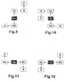
- FIG. 9 is a circuit diagram shown, in which the shift position R for engaging a reverse gear and the shift position D for the engagement of a forward gear with respect to the basic position X are arranged point-symmetrical. Next, the in FIG. 9 shown circuit diagram a switching position P for the insertion of a parking brake. Overall, this results in a staircase-shaped course of the individual switching positions.
- FIG. 10 shown circuit diagram is with the exception of the arrangement of the switching position P mirror symmetry to that in FIG. 9 shown circuit diagram.
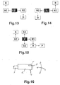
- FIGS. 11 and 12 Schematics shown are also mirror-symmetrical to each other and differ from the in FIG. 9 and FIG. 10 shown schematics, inter alia, that in the FIGS. 9 and 10 the shift position R is arranged with respect to the home position X of the selecting device in the forward direction of a vehicle in which the signal generator according to the invention is mounted, and the shift position D with respect to the basic position X of the selector in the reverse direction of the vehicle is arranged, whereas FIGS. 11 and 12 the shift position R with respect to the basic position X of the selector in the reverse direction and the shift position D with respect to the basic position X of the selector in the forward direction of travel of the vehicle is arranged.
- FIGS. 11 and 12 of the FIGS. 9 and 10 differ in that in the FIGS. 11 and 12 no switching position P is provided.
- FIGS. 9 and 10 the insertion of a drive gear D, R by deflecting the selection device is transverse to the vehicle direction.
- FIGS. 13 and 14 correspond to the FIGS. 11 and 12 wherein the arrangement of the shift position R for the engagement of a reverse gear and the shift position D for the engagement of a forward gear is respectively reversed.
- FIG. 15 shows a signal generator with a deflectable in four directions selection device, which is designed so that by means of the selection device in addition to setting the operating conditions of the automatic switching device of the gear change further devices are controllable, so that the selection device can be designed as a multi-functional element.
- the circuit diagram for setting the operating states of the automatic switching device of the gear change transmission corresponds to the in FIG. 11 shown circuit diagram, in addition, a switching position P is provided for the insertion of a parking brake.
- the additional shift positions S1 and S2 serve to select additional functions of the transmission or other devices (e.g., navigation device, radio, etc.).
- the selection device of the signal generator according to the invention can be designed for example in the form of a shift lever and mounted on a center console of a vehicle (not shown).
- the selector is as in FIG. 16 shown, executed in the form of a steering column lever 1 and pivotally connected to a (not shown) steering column of a vehicle, so that the selection device can be moved in one or more steering wheel planes and in these planes perpendicular.
- the steering column lever 1 has an actuating knob 2, which at the end of a Steering rod lever rod 3 is mounted on, wherein the steering column lever rod 3 is pivotally mounted with its end, not shown, on a steering column, also not shown, of a motor vehicle.
- the steering column lever 1 serves as a selector of the signal generator according to the invention and has for this purpose at the end of the steering column lever rod 3, not shown, on electrical contacts.
- steering column lever 1 By closing the contacts in deflection of the steering column lever 1 switching commands are passed to an evaluation circuit, not shown, which controls the automatic switching device of the gear change transmission and optionally other devices.
- the steering column lever 1 is hinged to the steering column, that he according to the diagrams of the FIGS. 1 to 15 can be deflected and moves automatically after a deflection back to its normal position.
- the in FIG. 16 shown steering column lever 1 a button 4, which is used in circuit diagrams that do not have their own shift position for the insertion of a parking brake, to give a command for inserting a parking brake.
- the steering column lever 1 has a reverse lock button 5, wherein the steering column lever 1 is deflected only when the reverse lock button 5 in a shift position R for engaging a reverse gear.
- the signal generator according to the invention may also be connected to a display device, not shown, which indicates the respectively activated operating state of the automatic switching device of the gear change transmission.
- FIGS. 17-31 a selection of different circuit diagrams is shown, as they can be realized with the signal generator according to the invention.
- the fields highlighted in white designate unstable positions of the selection device, ie positions in which the selection direction only lingers as long as it is held there.
- the white filed fields are marked with the letters R, N, N1, N2, D, P, S1, S2.
- R stands for a shift position for the engagement of a reverse gear
- N, N1, N2 for shift positions for the interruption of the torque transmission in the gear change
- D for a shift position for the engagement of a forward gear
- P for a shift position for the engagement of a parking brake
- S1, S2 for switching positions for first and second additional functions.
- the fields highlighted in black and marked X symbolize the respective stable basic position of the selection device, ie the respective position in one Circuit diagram in which the selection device remains when it is not deflected or to which the selection device returns after it has been deflected into an unstable position.
- the arrows in the FIGS. 17-31 indicate the directions in which the selector can be deflected from a respective position.
- FIGS. 17-22 show circuit diagrams, as can be realized with a signal generator, the selector is deflected in only three directions
- Particularly advantageous to signalers with deflectable in three directions selection device is in addition to the simple structure of the selector of the small footprint of the feasible circuit diagrams.
- FIG. 17 shows a possible circuit diagram according to a first preferred embodiment of a switch according to the invention, in which the selection means for selecting the switching position N for the interruption of the torque transmission in the gear change transmission starting from the basic position X is deflected in a first direction, and for selecting the switching position R for the insertion a reverse gear starting from the switching position N is first deflected in a second direction, wherein the second direction is not opposite to the first direction and different from the first direction, and after deflection in the second direction is deflected back into the first direction.
- the selection device for selecting the shift position R for the engagement of a reverse gear starting from the shift position N overall a step-shaped course of the deflection movement.
- the first direction shown may be, for example, a direction toward an operator of the selection device (driver side), and in the second direction, a forward travel direction of a vehicle in which the signal generator according to the invention is mounted.
- the selector For selecting the shift position D for engagement of a forward gear, the selector is first deflected from the shift position N into a third direction which is a direction different from the first of the second direction and not a direction opposite to the first direction, and after deflection in the third direction again deflected in the first direction.
- a third direction which is a direction different from the first of the second direction and not a direction opposite to the first direction
- the selection device for Selecting the shift position D for the engagement of a forward gear starting from the shift position N in turn, an overall step-shaped course of the deflection movement.
- FIG. 17 shown circuit diagram is in the third direction to the opposite direction of the second direction and thus oriented in the reverse direction of the vehicle direction.
- the deflection of the selection device between the individual switching positions N and R or N and D is preferably carried out without a break by a single continuous step-shaped deflection movement of the selection device.
- FIG. 17 shown circuit diagram A particularly preferred embodiment of the in FIG. 17 shown circuit diagram is in FIG. 18 shown.
- FIG. 18 differs from FIG. 17 in that, by means of the selection device of the signal generator according to the invention, in addition to setting the operating states of the automatic shifting device of the gear change transmission, further devices can be controlled or additional functions can be selected.
- the selection device additionally a first switching position S1 for a first additional function and a second switching position S2 for a second additional function selectable, wherein the selection means for selecting the switching position S1 starting from the basic position X is deflected in a direction equal to the second Direction of FIG. 17 and thus equal to the forward direction of travel of the vehicle.
- the selection device is deflected starting from the basic position X in a direction which is equal to the third direction of FIG. 17 and thus equal to the reverse direction.
- the shift positions S1 and S2 can be used, for example, for manually switching the gear change transmission, but also for operating a navigation system, a chassis control, an air conditioner or control of any other device.
- FIG. 17 alternative embodiment is in FIG. 19 shown.
- FIG. 19 The diagram shown differs from that in FIG. 17 shown circuit diagram basically in that two switching positions N1, N2 for the Interruption of torque transmission are provided in the gear change transmission.
- the selection device can be deflected starting from the basic position X in a first or second direction, the first direction being unequal to the second direction.
- the second direction is the opposite direction to the first direction.
- the selection device is initially deflectable starting from the switching position N1 in a third direction, which is different from the first and second directions and no opposite direction to the first and second directions, and after deflection in the third direction again into the first or second direction second direction deflectable.
- the selection device For selecting the shift position D, the selection device is initially deflectable starting from the shift position N2 in a direction which is likewise equal to the third direction, and can be deflected back into the first or second direction after deflection in the third direction.
- the selection device for selecting the shift position D for the engagement of a forward gear, starting from the shift position N2 there is again an overall step-shaped course of the deflection movement.
- FIG. 20 a schematic diagram is shown that differs from the one in FIG. 17 distinguished switching diagram characterized in that by means of the selection device additionally a shift position P is selected for the insertion of a parking brake, wherein the selection means for selecting the shift position P starting from the shift position R first in the second direction of FIG. 17 and thus in the forward direction of travel of the vehicle is deflectable, and deflected after deflection in the second direction in a direction which is equal to the first direction of FIG. 17 and is thus oriented towards an operator of the selection device (driver side).
- the selection device for selecting the shift position P for the insertion of a parking brake starting from the shift position R overall a step-shaped course of the deflection movement.
- FIG. 21 shows a modification of the in FIG. 19 Shown diagram, the analog to
- FIG. 20 has a shift position P for the insertion of a parking brake.
- FIG. 22 is shown a circuit diagram, starting from the basic position X by deflecting the selector in a direction associated with FIG. 19 has been referred to as "third direction", directly permitting selection of the shift position P.
- third direction directly permitting selection of the shift position P.
- FIGS. 23-31 show circuit diagrams, as they can be realized with a signal generator according to the invention, the selector is deflected in four directions. This allows a significant increase in the number of feasible circuit diagrams.
- FIG. 23 The diagram shows the related diagram FIG. 17 and differs therefrom in that the selection device for selecting the switching position P can be deflected starting from the basic position X in a fourth direction, which differs from that in connection with FIG FIG. 17 described first, second and third directions is different.
- the fourth direction corresponds to deflecting the selector away from an operator of the selector and thus towards the passenger side.
- FIG. 24 is that related to FIG. 19 described circuit diagram picked up again, the in FIG. 24 shown circuit diagram analogous to FIG. 23 additionally one from the. Basic position X directly accessible switching position P for inserting a parking brake.
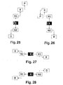
- FIG. 25 is a circuit diagram shown, in which the shift position R for engaging a reverse gear and the shift position D for the engagement of a forward gear with respect to the basic position X are arranged point-symmetrical. Next, the in FIG. 25 shown circuit diagram a switching position P for the insertion of a parking brake. Overall, this results in a stepped arrangement of the individual switching positions of the selection device.
- FIG. 26 shown circuit diagram is with the exception of the arrangement of the switching position P mirror symmetry to that in FIG. 25 shown circuit diagram.
- FIGS. 27 and 28 Schematics shown are also mirror-symmetrical to each other and differ from the in FIG. 25 and FIG. 26 shown schematics, inter alia, that in the FIGS. 25 and 26 the shift position R is arranged with respect to the home position X of the selecting device in the forward direction of a vehicle in which the signal generator according to the invention is mounted, and the shift position D with respect to the basic position X of the selector in the reverse direction of the vehicle is arranged, whereas FIGS. 27 and 28 the shift position R with respect to the basic position X of the selector in the reverse direction and the shift position D with respect to the basic position X of the selector in the forward direction of travel of the vehicle is arranged.
- FIGS. 27 and 28 of the FIGS. 25 and 26 differ in that in the FIGS. 27 and 28 no switching position P is provided.
- the basic deflection direction of the selection device between the individual switching positions N1, N2, R, P, D is not the same as in FIGS FIGS. 25 and 26 in the vehicle longitudinal direction, but is oriented in the vehicle transverse direction.
- FIGS. 29 and 30 correspond to the FIGS. 27 and 28 wherein the arrangement of the shift position R for the engagement of a reverse gear and the shift position D for the engagement of a forward gear is respectively reversed.
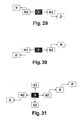
- FIG. 31 shows a signal generator with a deflectable in four directions selection device, which is designed so that by means of the selection device in addition to setting the operating conditions of the automatic switching device of the gear change further devices are controllable, so that the selection device can be designed as a multi-functional element.
- the circuit diagram for setting the operating states of the automatic switching device of the gear change transmission corresponds to the in FIG. 27 shown circuit diagram, in addition, a switching position P is provided for the insertion of a parking brake.
- the additional shift positions S1 and S2 serve to select additional functions of the transmission or to operate other devices (e.g., navigation device, radio, etc.).
- the selection device of the signal generator according to the invention can for example be designed in the form of a shift lever and attached to a center console of a vehicle.
- the selection device is designed in the form of a steering column lever and articulated to a steering column of a vehicle, so that the selection device can be moved in one or more steering wheel planes and in planes perpendicular thereto.
- the steering column lever has an operating knob which is attached to one end of a steering column lever rod, wherein the steering column lever rod is pivotally attached at its other end to the steering column of the motor vehicle.
- the steering column lever serves as a selector of the signal generator according to the invention and has for this purpose at its end connected to the steering column end of the steering column lever rod electrical contacts. By closing the contacts upon deflection of the steering column lever switching commands are passed to an evaluation circuit that controls the automatic switching device of the gear change transmission and optionally other devices.
- the steering column lever is hinged to the steering column, that he according to the circuit diagrams of the FIGS. 17 to 31 can be deflected and moves automatically after a deflection back to its normal position.
- the steering column lever preferably has a button which, in the case of circuit diagrams which do not have their own shift position for the engagement of a parking brake, serves to issue a command for engaging a parking brake.
- the steering column lever preferably has a reverse lock button, wherein the steering column lever is deflected only with the reverse lock button pressed in a shift position R for engaging a reverse gear.
- the signal generator according to the invention may also be connected to a display device which indicates the respectively activated operating state of the automatic switching device of the gear change transmission.
Abstract
Claims (34)
- Emetteur de signal pour régler les états de fonctionnement d'un dispositif de changement automatique d'une boîte de vitesses, présentant un dispositif de sélection (1) qui peut dévier dans au moins trois directions et revenant au moins pour certaines positions de changement automatiquement dans une position de base (X), au moyen duquel on peut choisir la au moins une position de changement (R) pour passer une marche arrière, une position de changement (N) pour interrompre la transmission du couple de torsion dans la boîte de vitesses et une position de changement (D) pour passer une marche avant, dans lequel :le dispositif de sélection (1) peut, pour sélectionner la position de changement (N ; N1, N2) afin d'interrompre la transmission du couple de torsion dans la boîte de vitesses, être dévié de la position de base (X) dans une première direction et le dispositif de sélection (1) peut, pour sélectionner l'une des autres positions de changement (R, D) à partir de la position de changement (N ; N1, N2) afin d'interrompre la transmission du couple de torsion dans la boîte de vitesses, être dévié respectivement dans une autre direction différente de la première direction, qui n'est pas la direction opposée à la première direction, caractérisé en ce que le dispositif de sélection (1) est amené de la position de base stable (X) d'abord par déviation dans la première direction dans la position de changement instable (N ; N1, N2) pour interrompre la transmission du couple de torsion dans la boîte de vitesses, puis par déviation dans l'autre direction différente de la première direction dans l'autre position de changement instable (RD).
- Emetteur de signal selon la revendication 1,
caractérisé en ce que
le dispositif de sélection (1) peut, pour sélectionner la position de changement (R) pour passer une marche arrière à partir de la position de changement (N) pour interrompre la transmission du couple de torsion dans la boîte de vitesses, être dévié dans une deuxième direction, qui n'est pas la direction opposée à la première direction et qui est différente de la première direction, et le dispositif de sélection (1) peut, pour sélectionner la position de changement (D) pour passer une marche avant à partir de la position de changement (N) pour interrompre la transmission du couple de torsion dans la boîte de vitesses, être dévié dans une troisième direction, qui est différente des première et deuxième directions et qui n'est pas la direction opposée à la première direction. - Emetteur de signal selon la revendication 1 ou 2,
caractérisé en ce que
l'émetteur de signal est réalisé de sorte qu'au moyen du dispositif de sélection (1), d'autres dispositifs puissent être commandés en plus pour le réglage des états de fonctionnement du dispositif de changement automatique de la boîte de vitesses. - Emetteur de signal selon les revendications 3 et 2,
caractérisé en ce que
une position de changement (S1) pour une première fonction supplémentaire et une position de changement (S2) pour une deuxième fonction supplémentaire peuvent encore être sélectionnées au moyen du dispositif de sélection (1), en ce que le dispositif de sélection (1) peut, pour sélectionner la position de changement (S1) pour une première fonction supplémentaire à partir de la position de base (X), être dévié dans une direction qui est identique à la deuxième direction et en ce que le dispositif de sélection (1) peut, pour sélectionner la position de changement (S2) pour une deuxième fonction supplémentaire à partir de la position de base (X), être dévié dans une direction qui est identique à la troisième direction. - Emetteur de signal selon la revendication 1,
caractérisé en ce que
il est prévu une première et une deuxième positions de changement (N1, N2) pour interrompre la transmission du couple de torsion dans la boîte de vitesses, le dispositif de sélection (1) peut, pour sélectionner la première ou la deuxième position de changement (N1, N2) pour interrompre la transmission du couple de torsion dans la boîte de vitesses, à partir de la position de base (X), être dévié dans la première ou la deuxième direction, la première direction n'étant pas identique à la deuxième direction, le dispositif de sélection (1) peut, pour sélectionner la position de changement (R) pour passer une marche arrière à partir de la première position de changement (N1) pour interrompre la transmission du couple de torsion dans la boîte de vitesses, être dévié dans une troisième direction qui est différente des première et deuxième directions et qui n'est pas la direction opposée aux première et deuxième directions et le dispositif de sélection (1) peut, pour sélectionner la position de changement (D) pour passer une marche avant à partir de la deuxième position de changement (N2) pour interrompre la transmission du couple de torsion dans la boîte de vitesses, être dévié dans une direction qui est identique à la troisième direction. - Emetteur de signal selon l'une quelconque des revendications précédentes,
caractérisé en ce que
une position de changement (P) pour appliquer un frein de stationnement peut encore être sélectionnée au moyen du dispositif de sélection (1). - Emetteur de signal selon la revendication 6,
caractérisé en ce que,
pour sélectionner la position de changement (P) pour appliquer un frein de stationnement, le dispositif de sélection (1) peut, à partir de la position de changement (R) pour passer une marche arrière, être dévié dans une direction qui est identique à la première direction. - Emetteur de signal selon les revendications 6 et 5 caractérisé en ce que,
pour sélectionner la position de changement (P) pour appliquer un frein de stationnement, le dispositif de sélection (1) peut, à partir de la position de base (X), être dévié dans une direction qui est identique à la troisième direction. - Emetteur de signal selon l'une quelconque des revendications précédentes,
caractérisé en ce que
le dispositif de sélection (1) peut être dévié dans quatre directions. - Emetteur de signal selon les revendications 9 et 2 ou 5,
caractérisé en ce que,
pour sélectionner la position de changement (P) pour appliquer un frein de stationnement, le dispositif de sélection (1) peut, à partir de la position de base (X), être dévié dans une quatrième direction qui est différente des première, deuxième et troisième directions. - Emetteur de signal selon la revendication 9,
caractérisé en ce que
il est prévu une première et une deuxième position de changement (N1, N2) pour interrompre la transmission du couple de torsion dans la boîte de vitesses, le dispositif de sélection (1) peut, pour sélectionner les première et deuxième positions de changement (N1, N2) pour interrompre la transmission du couple de torsion dans la boîte de vitesses, à partir de la position de base (X), être dévié dans une première ou une deuxième direction, la première direction n'étant pas identique à la deuxième direction, le dispositif de sélection (1) peut, pour sélectionner la position de changement (R) pour passer une marche arrière à partir de la première position de changement (N1) pour interrompre la transmission du couple de torsion dans la boîte de vitesses, être dévié dans une troisième direction qui est différente des première et deuxième directions et qui n'est pas la direction opposée aux première et deuxième directions et le dispositif de sélection (1) peut, pour sélectionner la position de changement (D) pour passer une marche avant à partir de la deuxième position de changement (N2) pour interrompre la transmission de couple dans la boîte de vitesses, être dévié dans une quatrième direction qui est différente des première, deuxième et troisième directions et qui n'est pas la direction opposée aux première et deuxième directions. - Emetteur de signal selon la revendication 11,
caractérisé en ce que,
pour sélectionner la position de changement (P) pour appliquer un frein de stationnement, le dispositif de sélection (1) peut, à partir de la position de changement (R) pour passer une marche arrière, être dévié dans une direction qui est identique à la première ou à la deuxième direction. - Emetteur de signal selon la revendication 11,
caractérisé en ce que
une position de changement (S1) pour une première fonction supplémentaire et une position de changement (S2) pour une deuxième fonction supplémentaire peuvent encore être sélectionnées au moyen du dispositif de sélection (1) et, pour sélectionner la position de changement (S1) pour une première fonction supplémentaire, le dispositif de sélection (1) peut être dévié de la position de base (X) dans une direction qui est identique à la troisième direction et, pour sélectionner la position de changement (S2) pour une deuxième fonction supplémentaire, le dispositif de sélection (1) peut être dévié de la position de base (X) dans une direction qui est identique à la quatrième direction. - Emetteur de signal selon l'une quelconque des revendications précédentes,
caractérisé en ce que
l'émetteur de signal présente en outre une touche de stationnement (4) et un frein de stationnement peut être appliqué par pression de la touche de stationnement (4). - Emetteur de signal selon la revendication 14,
caractérisé en ce que
la touche de stationnement (4) est aménagée sur le dispositif de sélection (1). - Emetteur de signal selon l'une quelconque des revendications précédentes,
caractérisé en ce que
l'émetteur de signal présente en outre une touche d'arrêt de recul (5) et le dispositif de sélection (1) ne peut, pour sélectionner la position de changement (R) pour passer une marche arrière, être dévié que lorsque la touche d'arrêt de recul (5) est enfoncée. - Emetteur de signal selon la revendication 16,
caractérisé en ce que
la touche d'arrêt de recul (5) est aménagée sur le dispositif de sélection (1). - Emetteur de signal selon l'une quelconque des revendications précédentes,
caractérisé en ce que
l'émetteur de signal est monté dans un véhicule. - Emetteur de signal selon la revendication 18,
caractérisé en ce que
la position de changement (R) pour passer une marche arrière, par rapport à la position de base (X) du dispositif de sélection (1), est aménagée dans la direction de marche avant du véhicule et la position de changement (D) pour passer une marche avant, par rapport à la position de base (X) du dispositif de sélection (1), est aménagée dans la direction de marche arrière du véhicule. - Emetteur de signal selon la revendication 18,
caractérisé en ce que
la position de changement (R) pour passer une marche arrière, par rapport à la position de base (X) du dispositif de sélection (1), est aménagée dans la direction de marche arrière du véhicule et la position de changement (D) pour passer une marche avant, par rapport à la position de base (X) du dispositif de sélection (1), est aménagée dans la direction de marche avant du véhicule. - Emetteur de signal selon l'une quelconque des revendications 18 à 20, caractérisé en ce que
la position de changement (R) pour passer une marche arrière et la position de changement (D) pour passer une marche avant sont aménagées en symétrie ponctuelle par rapport à la position de base (X) du dispositif de sélection (1). - Emetteur de signal selon l'une quelconque des revendications 18 à 21, caractérisé en ce que
le dispositif de sélection (1) se présente sous la forme d'un levier de direction aménagé sur une colonne de direction du véhicule. - Emetteur de signal selon l'une quelconque des revendications 18 à à 21,
caractérisé en ce que
le dispositif de sélection (1) se présente sous la forme d'un levier de commande aménagé sur une console centrale du véhicule. - Emetteur de signal
caractérisé en ce que
le dispositif de sélection (1) peut, pour sélectionner la position de changement (N ; N1, N2) pour interrompre la transmission du couple de torsion dans la boîte de vitesses, être dévié de la position de base (X) dans une première direction et le dispositif de sélection (1) peut, pour sélectionner l'une des autres positions de changement (R, D), être dévié de la position de changement (N ; N1, N2) pour interrompre la transmission du couple de torsion dans la boîte de vitesses, d'abord respectivement dans l'autre direction différente de la première direction, qui n'est pas la direction opposée à la première direction, et, après avoir été dévié dans l'autre direction respective, peut être dévié à nouveau dans la première direction. - Emetteur de signal selon la revendication 24,
caractérisé en ce que
le dispositif de sélection (1) peut, pour sélectionner de la position de changement (R) pour passer une marche arrière, être dévié de la position de changement (N) pour interrompre la transmission du couple de torsion dans le boîte de vitesses dans une deuxième direction, qui n'est pas la direction opposée à la première direction et qui est différente de la première direction et, après avoir été dévié dans la deuxième direction, peut être dévié à nouveau dans la première direction et le dispositif de sélection (1) peut, pour sélectionner la position de changement (D) pour passer une marche avant, être dévié de la position de changement (N) pour interrompre la transmission du couple de torsion dans la boîte de vitesses dans une troisième direction, qui est une direction différente des première et deuxième directions et qui n'est pas la direction opposée à la première direction et, après avoir été dévié dans la troisième direction, peut être dévié à nouveau dans la première direction. - Emetteur de signal selon la revendication 24 ou 25,
caractérisé en ce que
l'émetteur de signal est réalisé de sorte qu'au moyen du dispositif de sélection (1), d'autres dispositifs puissent être commandés en plus pour le réglage des états de fonctionnement du dispositif de changement automatique de la boîte de vitesses. - Emetteur de signal selon les revendications 26 et 25,
caractérisé en ce que
une position de changement (S1) pour une première fonction supplémentaire et une position de changement (S2) pour une deuxième fonction supplémentaire peuvent encore être sélectionnées au moyen du dispositif de sélection (1), le dispositif de sélection (1) peut, pour sélectionner la position de changement (S1) pour une première fonction supplémentaire, être dévié de la position de base (X) dans une direction qui est identique à la deuxième direction et le dispositif de sélection (1) peut, pour sélectionner la position de changement (S2) pour une deuxième fonction supplémentaire, être dévié de la position de base (X) dans une direction qui est identique à la troisième direction. - Emetteur de signal selon la revendication 24,
caractérisé en ce que
il est prévu une première et une deuxième position de changement (N1, N2) pour interrompre la transmission du couple de torsion dans la boîte de vitesses, le dispositif de sélection (1) peut, pour sélectionner les première ou deuxième positions de changement (N1, N2) pour interrompre la transmission du couple de torsion dans la boîte de vitesses, être dévié de la position de base (X) dans la première ou la deuxième direction, la première direction n'étant pas identique à la deuxième direction, le dispositif de sélection (1) peut, pour sélectionner la position de changement (R) pour passer une marche arrière, être d'abord dévié de la première position de changement (N1) pour interrompre la transmission du couple de torsion dans la boîte de vitesses dans une troisième direction qui est différente des première et deuxième directions et qui n'est pas la direction opposée aux première et deuxième directions et, après avoir été dévié dans la troisième direction, peut être dévié à nouveau dans la première ou la deuxième direction et le dispositif de sélection (1) peut, pour sélectionner la position de changement (D) pour passer une marche avant, être d'abord dévié de la deuxième position de changement (N2) pour interrompre la transmission du couple de torsion dans la boîte de vitesses dans une direction qui est identique à la troisième direction et, après avoir été dévié dans la troisième direction, peut être dévié à nouveau dans la première ou la deuxième direction. - Emetteur de signal selon l'une quelconque des revendications précédentes 24 à 28,
caractérisé en ce que
une position de changement (P) pour appliquer un frein de stationnement peut encore être sélectionnée au moyen du dispositif de sélection (1). - Emetteur de signal selon la revendication 29,
caractérisé en ce que,
pour sélectionner la position de changement (P) pour appliquer un frein de stationnement, le dispositif de sélection (1) peut être dévié de la position de changement (R) pour passer une marche arrière d'abord dans l'autre direction respective et, après avoir été dévié dans l'autre direction respective, peut être dévié dans une direction qui est identique à la première direction ou à une direction opposée à la première direction. - Emetteur de signal selon l'une quelconque des revendications précédentes 24 à 30,
caractérisé en ce que
le dispositif de sélection (1) peut être dévié dans quatre directions. - Emetteur de signal selon la revendication 31,
caractérisé en ce que
il est prévu une première et une deuxième position de changement (N1, N2) pour interrompre la transmission du couple de torsion dans la boîte de vitesses, le dispositif de sélection (1) peut, pour sélectionner la première ou la deuxième position de changement (N1, N2) pour interrompre la transmission du couple de torsion dans la boîte de vitesses, être dévié de la position de base (X) dans la première direction ou dans une deuxième direction, la première direction n'étant pas identique à la deuxième direction, le dispositif de sélection (1) peut, pour sélectionner la position de changement (R) pour passer une marche arrière, être d'abord dévié de la première position de changement (N1) pour interrompre la transmission du couple de torsion dans la boîte de vitesses dans une troisième direction qui est différente des première et deuxième directions et qui n'est pas une direction opposée aux première et deuxième directions et, après avoir été dévié dans la troisième direction, peut être dévié à nouveau dans la première ou la deuxième direction et le dispositif de sélection (1) peut, pour sélectionner la position de changement (D) pour passer une marche avant, être d'abord dévié de la deuxième position de changement (N2) pour interrompre la transmission du couple de torsion dans la boîte de vitesses dans une quatrième direction, qui est différente des première, deuxième et troisième directions et qui n'est pas une direction opposée aux première et deuxième directions, et, après avoir été dévié dans la quatrième direction, peut être dévié à nouveau dans la première ou la deuxième direction. - Emetteur de signal selon la revendication 32,
caractérisé en ce que,
pour sélectionner la position de changement (P) pour appliquer un frein de stationnement, le dispositif de sélection (1) peut d'abord être dévié de la position de changement (R) pour passer une marche arrière d'abord dans la troisième ou la quatrième direction et, après avoir été dévié dans la troisième ou la quatrième direction, peut être dévié dans une direction qui est identique à la première ou à la deuxième direction. - Emetteur de signal selon la revendication 32,
caractérisé en ce que
une position de changement (S1) pour une première fonction supplémentaire et une position de changement (S2) pour une deuxième fonction supplémentaire peuvent encore être sélectionnées au moyen du dispositif de sélection (1) et, pour sélectionner la position de changement (S1) pour une première fonction supplémentaire, le dispositif de sélection (1) peut être dévié de la position de base (X) dans une direction qui est identique à la troisième direction et, pour sélectionner la position de changement (S2) pour une deuxième fonction supplémentaire, le dispositif de sélection (1) peut être dévié de la position de base (X) dans une direction qui est identique à la quatrième direction.
Applications Claiming Priority (5)
| Application Number | Priority Date | Filing Date | Title |
|---|---|---|---|
| DE2001149264 DE10149264A1 (de) | 2001-11-16 | 2001-10-05 | Signalgeber zum Einstellen der Betriebszustände einer selbsttätigen Schaltvorrichtung |
| DE10149264 | 2001-10-05 | ||
| DE10156091 | 2001-11-16 | ||
| DE10156091A DE10156091A1 (de) | 2001-10-05 | 2001-11-16 | Signalgeber zum Einstellen der Betriebszustände einer selbsttätigen Schaltvorrichtung |
| PCT/DE2002/003678 WO2003031845A1 (fr) | 2001-10-05 | 2002-09-27 | Emetteur de signaux concu pour regler les etats de fonctionnement d'un dispositif de commutation automatique |
Publications (2)
| Publication Number | Publication Date |
|---|---|
| EP1432934A1 EP1432934A1 (fr) | 2004-06-30 |
| EP1432934B1 true EP1432934B1 (fr) | 2010-08-11 |
Family
ID=26010308
Family Applications (1)
| Application Number | Title | Priority Date | Filing Date |
|---|---|---|---|
| EP02776737A Expired - Lifetime EP1432934B1 (fr) | 2001-10-05 | 2002-09-27 | Emetteur de signaux concu pour regler les etats de fonctionnement d'un dispositif de commutation automatique |
Country Status (5)
| Country | Link |
|---|---|
| US (1) | US6904822B2 (fr) |
| EP (1) | EP1432934B1 (fr) |
| JP (1) | JP4373212B2 (fr) |
| DE (1) | DE10156091A1 (fr) |
| WO (1) | WO2003031845A1 (fr) |
Families Citing this family (21)
| Publication number | Priority date | Publication date | Assignee | Title |
|---|---|---|---|---|
| DE10206985B4 (de) | 2002-02-20 | 2012-07-26 | Bayerische Motoren Werke Aktiengesellschaft | Getriebeschalteinrichtung |
| DE102004054264B4 (de) * | 2004-11-09 | 2007-08-09 | Zf Friedrichshafen Ag | Betätigungseinrichtung mit Drehschalter |
| JP4723918B2 (ja) * | 2005-06-03 | 2011-07-13 | トヨタ自動車株式会社 | 車両用シフトレバー装置 |
| DE102005062298A1 (de) * | 2005-12-24 | 2007-06-28 | Dr.Ing.H.C. F. Porsche Ag | Schaltvorrichtung für ein Getriebe |
| DE102006059992A1 (de) * | 2006-12-19 | 2008-06-26 | Daimler Ag | Schaltungsbedienelement für ein Getriebe eines Kraftfahrzeugs mit elektronisch gesteuerter Schaltung |
| JP4844749B2 (ja) * | 2007-03-16 | 2011-12-28 | スズキ株式会社 | シフトバイワイヤ式変速制御装置 |
| JP4500327B2 (ja) * | 2007-06-07 | 2010-07-14 | 本田技研工業株式会社 | シフト装置 |
| DE102007037707A1 (de) * | 2007-08-09 | 2009-02-19 | Zf Friedrichshafen Ag | Betätigungseinrichtung mit Gangwahlelement und zusätzlicher Parksperrenbetätigung |
| DE102007047120B4 (de) * | 2007-10-02 | 2013-01-10 | Audi Ag | Schalteinheit für ein insbesondere elektronisch geschaltetes Getriebe eines Kraftfahrzeugs |
| US9068649B2 (en) * | 2008-05-30 | 2015-06-30 | GM Global Technology Operations LLC | Gear and mode selection for transmissions using a single input device |
| DE102010013169B4 (de) * | 2010-03-27 | 2013-06-20 | Audi Ag | Bedienvorrichtung für ein Kraftfahrzeug |
| JP5963857B2 (ja) * | 2012-06-08 | 2016-08-03 | 本田技研工業株式会社 | 車両用シフト装置 |
| JP6026800B2 (ja) * | 2012-07-11 | 2016-11-16 | 株式会社東海理化電機製作所 | シフト装置 |
| KR101393973B1 (ko) * | 2012-12-06 | 2014-05-12 | 현대자동차주식회사 | Dct 차량의 변속조작장치 및 그 제어방법 |
| US9169923B2 (en) | 2013-09-05 | 2015-10-27 | Honda Motor Co., Ltd. | Methods and systems for shifting a transmission gear |
| JP6167779B2 (ja) * | 2013-09-10 | 2017-07-26 | マツダ株式会社 | 車両用シフト装置 |
| JP6156301B2 (ja) | 2014-09-18 | 2017-07-05 | マツダ株式会社 | 車両用シフタ装置 |
| EP3106715A1 (fr) | 2015-06-19 | 2016-12-21 | Fico Triad, S.A. | Changement de vitesse monostable par dispositif de changement de vitesse à fil |
| WO2018006955A1 (fr) * | 2016-07-06 | 2018-01-11 | Kongsberg Automotive Ab | Ensemble de changement de vitesse pour transmission de véhicule automatique |
| JP6212614B2 (ja) * | 2016-09-07 | 2017-10-11 | 株式会社東海理化電機製作所 | シフト装置 |
| CN113202922A (zh) * | 2021-05-19 | 2021-08-03 | 东风汽车集团股份有限公司 | 一种车辆摇杆式电子换档器的档位切换控制方法 |
Family Cites Families (25)
| Publication number | Priority date | Publication date | Assignee | Title |
|---|---|---|---|---|
| US3068717A (en) * | 1959-09-24 | 1962-12-18 | Atwood Vacuum Machine Co | Push-button transmission selector |
| DE2050395A1 (de) * | 1970-10-14 | 1972-04-20 | Dr.Ing.H.C. F. Porsche Kg, 7000 Stuttgart | Schaltvorrichtung für automatische Geschwindigkeitswechselgetriebe von Fahrzeugen |
| JP2917628B2 (ja) | 1991-10-22 | 1999-07-12 | トヨタ自動車株式会社 | 自動変速機の操作装置 |
| FR2694525B1 (fr) | 1992-08-06 | 1994-11-04 | Peugeot | Dispositif de commande d'une boîte de vitesses automatique. |
| DE4305903A1 (de) * | 1993-02-26 | 1994-09-01 | Bayerische Motoren Werke Ag | Schaltvorrichtung für ein automatisch schaltendes Kraftfahrzeuggetriebe |
| US5462146A (en) * | 1993-07-06 | 1995-10-31 | Dura Mechanical Components, Inc. | Common shifter and parking brake mounting |
| GB9504681D0 (en) | 1995-03-08 | 1995-04-26 | Eaton Corp | Improvements in vehicle control |
| US6082213A (en) * | 1995-06-27 | 2000-07-04 | Scandmec Ab | Control device for the transmission of a vehicle |
| US5809835A (en) * | 1997-01-21 | 1998-09-22 | Ford Global Technologies, Inc. | Manual transmission shift lever |
| DE19714495A1 (de) * | 1997-04-08 | 1998-10-15 | Bayerische Motoren Werke Ag | Wähleinrichtung mit einer Anzeigeeinrichtung |
| DE19821361B4 (de) * | 1997-05-22 | 2006-07-06 | Volkswagen Ag | Getriebeschalteinrichtung und Getriebesteuerungsverfahren |
| DE19728064B4 (de) | 1997-07-01 | 2006-10-05 | Teleflex Automotive Germany Gmbh | Wählvorrichtung zum Einstellen von Kraftfahrzeug-Automatikgetrieben |
| DE19737296C2 (de) | 1997-08-27 | 1999-11-18 | Daimler Chrysler Ag | Selbsttätige Schaltvorrichtung eines Gangwechselgetriebes mit einem Handwählorgan |
| US6000296A (en) * | 1998-03-30 | 1999-12-14 | Chrysler Corporation | Gated selector lever and controls for automatic transmission and transfer case |
| SE513585C2 (sv) * | 1998-06-12 | 2000-10-02 | Kongsberg Automotive Ab | Manöveranordning innefattande en manöverspak och en manöverkonsol |
| EP0978670A3 (fr) | 1998-08-03 | 2002-07-17 | Toyota Jidosha Kabushiki Kaisha | Dispositif de propulsion véhiculaire avec dispositif pour éviter des erreurs de changement de vitesse, et dispositif de détermination de position de levier de vitesses |
| DE19916924A1 (de) * | 1999-04-14 | 2000-10-19 | Bayerische Motoren Werke Ag | Kraftfahrzeug mit einer Wähleinrichtung |
| FR2795150B1 (fr) * | 1999-06-17 | 2001-09-07 | Sc2N Sa | Dispositif de commande sans contact, notamment pour la commande de boite de vitesse automatisee |
| DE10059279B4 (de) | 1999-12-08 | 2013-07-25 | Schaeffler Technologies AG & Co. KG | Kraftfahrzeug mit Getriebe |
| DE10059277B4 (de) | 1999-12-08 | 2010-03-25 | Luk Lamellen Und Kupplungsbau Beteiligungs Kg | Kraftfahrzeug und Verfahren zum Betreiben eines Kraftfahrzeuges |
| JP2001277893A (ja) * | 2000-04-04 | 2001-10-10 | Tokai Rika Co Ltd | 車両用のスイッチ装置 |
| JP4456721B2 (ja) | 2000-04-27 | 2010-04-28 | 本田技研工業株式会社 | 自動変速機の制御装置 |
| US6588290B2 (en) * | 2001-02-02 | 2003-07-08 | International Truck Intellectual Property Company, Llc | Transmission shift control |
| DE10209104A1 (de) * | 2001-03-01 | 2002-09-26 | Tokai Rika Co Ltd | Schaltvorrichtung und zugehörige Umschaltvorrichtung für Fahrzeuge |
| DE10206985B4 (de) * | 2002-02-20 | 2012-07-26 | Bayerische Motoren Werke Aktiengesellschaft | Getriebeschalteinrichtung |
-
2001
- 2001-11-16 DE DE10156091A patent/DE10156091A1/de not_active Ceased
-
2002
- 2002-09-27 EP EP02776737A patent/EP1432934B1/fr not_active Expired - Lifetime
- 2002-09-27 WO PCT/DE2002/003678 patent/WO2003031845A1/fr active Application Filing
- 2002-09-27 US US10/433,911 patent/US6904822B2/en not_active Expired - Lifetime
- 2002-09-27 JP JP2003534788A patent/JP4373212B2/ja not_active Expired - Lifetime
Also Published As
| Publication number | Publication date |
|---|---|
| EP1432934A1 (fr) | 2004-06-30 |
| US20040025613A1 (en) | 2004-02-12 |
| WO2003031845A1 (fr) | 2003-04-17 |
| JP4373212B2 (ja) | 2009-11-25 |
| DE10156091A1 (de) | 2003-07-10 |
| US6904822B2 (en) | 2005-06-14 |
| JP2005504685A (ja) | 2005-02-17 |
Similar Documents
| Publication | Publication Date | Title |
|---|---|---|
| EP1432934B1 (fr) | Emetteur de signaux concu pour regler les etats de fonctionnement d'un dispositif de commutation automatique | |
| DE10206985B4 (de) | Getriebeschalteinrichtung | |
| EP0444250B1 (fr) | Dispositif de changement de vitesse pour transmission automatique | |
| EP1045172B1 (fr) | Dispositif de commande pour une boíte de vitesses automatique de véhicule automobile | |
| DE102005063444B4 (de) | Gangschaltungsvorrichtung für ein Handschaltgetriebe und Verfahren zum Steuern derselben | |
| DE102009039113B4 (de) | Schalteinheit für ein insbesondere elektronisch geschaltetes Getriebe eines Kraftfahrzeugs | |
| DE10042557B4 (de) | Eingabevorrichtung zur Verwendung in Fahrzeugen zum Eingeben von Einstellungen betreffend einer Absicht des Fahrers zur Beschleunigung und Verzögerung | |
| EP1801463B1 (fr) | Dispositif pour changer la vitesse pour une boîte de vitesses | |
| EP0416227B1 (fr) | Transmission pour véhicule automobile | |
| EP0107761A2 (fr) | Changement de vitesse pour transmission à commande par force séparée | |
| WO2008074375A1 (fr) | Elément de commande de commutation pour une boîte de vitesses d'un véhicule automobile avec commutation à commande électronique | |
| DE10217614B4 (de) | Bedienelement zum Anwählen von Betriebszuständen eines Getriebes | |
| EP0999383A2 (fr) | Dispositif de changement de vitesse pour une transmission automatique d'une véhicule automobile | |
| EP1728146A1 (fr) | Dispositif d'affichage et de commande | |
| DE102005048875B4 (de) | Schalteinheit für ein elektronisch geschaltetes Getriebe eines Kraftfahrzeugs | |
| DE102006007008B4 (de) | Kraftfahrzeug mit wenigstens einem Fahrerassistenzsystem | |
| DE4305903A1 (de) | Schaltvorrichtung für ein automatisch schaltendes Kraftfahrzeuggetriebe | |
| DE102015120300B4 (de) | Schalteinrichtung | |
| DE3924318A1 (de) | Schaltung fuer ein kraftfahrzeuggetriebe | |
| EP1380773B1 (fr) | Dispositif et procédé pour commander une boîte automatique d'un véhicule automobile | |
| DE19849076A1 (de) | Wähleinrichtung für ein automatisch geschaltetes Getriebe eines Kraftfahrzeugs | |
| EP1081414B1 (fr) | Dispositif de changement de vitesses pour commander une transmission automatique de véhicule automobile | |
| DE10105491B4 (de) | Schaltvorrichtung für ein Getriebe | |
| DE10149264A1 (de) | Signalgeber zum Einstellen der Betriebszustände einer selbsttätigen Schaltvorrichtung | |
| EP1213510B1 (fr) | Sélecteur des vitesses et appareil de commande pour moteur à combustion dans un véhicule |
Legal Events
| Date | Code | Title | Description |
|---|---|---|---|
| PUAI | Public reference made under article 153(3) epc to a published international application that has entered the european phase |
Free format text: ORIGINAL CODE: 0009012 |
|
| 17P | Request for examination filed |
Effective date: 20030425 |
|
| AK | Designated contracting states |
Kind code of ref document: A1 Designated state(s): AT BE BG CH CY CZ DE DK EE ES FI FR GB GR IE IT LI LU MC NL PT SE SK TR |
|
| R17P | Request for examination filed (corrected) |
Effective date: 20030425 |
|
| 17Q | First examination report despatched |
Effective date: 20090511 |
|
| GRAP | Despatch of communication of intention to grant a patent |
Free format text: ORIGINAL CODE: EPIDOSNIGR1 |
|
| GRAS | Grant fee paid |
Free format text: ORIGINAL CODE: EPIDOSNIGR3 |
|
| GRAA | (expected) grant |
Free format text: ORIGINAL CODE: 0009210 |
|
| AK | Designated contracting states |
Kind code of ref document: B1 Designated state(s): DE ES FR GB IT SE |
|
| REG | Reference to a national code |
Ref country code: GB Ref legal event code: FG4D Free format text: NOT ENGLISH |
|
| REF | Corresponds to: |
Ref document number: 50214585 Country of ref document: DE Date of ref document: 20100923 Kind code of ref document: P |
|
| REG | Reference to a national code |
Ref country code: SE Ref legal event code: TRGR |
|
| RAP2 | Party data changed (patent owner data changed or rights of a patent transferred) |
Owner name: ZF LEMFOERDER GMBH |
|
| PLBI | Opposition filed |
Free format text: ORIGINAL CODE: 0009260 |
|
| PLAX | Notice of opposition and request to file observation + time limit sent |
Free format text: ORIGINAL CODE: EPIDOSNOBS2 |
|
| 26 | Opposition filed |
Opponent name: RENAULT S.A.S Effective date: 20110511 |
|
| REG | Reference to a national code |
Ref country code: DE Ref legal event code: R026 Ref document number: 50214585 Country of ref document: DE Effective date: 20110511 |
|
| REG | Reference to a national code |
Ref country code: DE Ref legal event code: R081 Ref document number: 50214585 Country of ref document: DE Owner name: ZF FRIEDRICHSHAFEN AG, DE Free format text: FORMER OWNER: ZF LEMFOERDER METALLWAREN AG, 49448 LEMFOERDE, DE Effective date: 20110715 |
|
| PLAF | Information modified related to communication of a notice of opposition and request to file observations + time limit |
Free format text: ORIGINAL CODE: EPIDOSCOBS2 |
|
| PLBB | Reply of patent proprietor to notice(s) of opposition received |
Free format text: ORIGINAL CODE: EPIDOSNOBS3 |
|
| RAP2 | Party data changed (patent owner data changed or rights of a patent transferred) |
Owner name: ZF FRIEDRICHSHAFEN AG |
|
| REG | Reference to a national code |
Ref country code: DE Ref legal event code: R081 Ref document number: 50214585 Country of ref document: DE Owner name: ZF FRIEDRICHSHAFEN AG, DE Free format text: FORMER OWNER: ZF LEMFOERDER GMBH, 49448 LEMFOERDE, DE Effective date: 20120626 |
|
| PLAB | Opposition data, opponent's data or that of the opponent's representative modified |
Free format text: ORIGINAL CODE: 0009299OPPO |
|
| R26 | Opposition filed (corrected) |
Opponent name: RENAULT S.A.S Effective date: 20110511 |
|
| PLCK | Communication despatched that opposition was rejected |
Free format text: ORIGINAL CODE: EPIDOSNREJ1 |
|
| APAH | Appeal reference modified |
Free format text: ORIGINAL CODE: EPIDOSCREFNO |
|
| APBM | Appeal reference recorded |
Free format text: ORIGINAL CODE: EPIDOSNREFNO |
|
| APBP | Date of receipt of notice of appeal recorded |
Free format text: ORIGINAL CODE: EPIDOSNNOA2O |
|
| APBQ | Date of receipt of statement of grounds of appeal recorded |
Free format text: ORIGINAL CODE: EPIDOSNNOA3O |
|
| REG | Reference to a national code |
Ref country code: FR Ref legal event code: PLFP Year of fee payment: 15 |
|
| REG | Reference to a national code |
Ref country code: DE Ref legal event code: R100 Ref document number: 50214585 Country of ref document: DE |
|
| APBU | Appeal procedure closed |
Free format text: ORIGINAL CODE: EPIDOSNNOA9O |
|
| PLBN | Opposition rejected |
Free format text: ORIGINAL CODE: 0009273 |
|
| STAA | Information on the status of an ep patent application or granted ep patent |
Free format text: STATUS: OPPOSITION REJECTED |
|
| 27O | Opposition rejected |
Effective date: 20170216 |
|
| REG | Reference to a national code |
Ref country code: FR Ref legal event code: PLFP Year of fee payment: 16 |
|
| REG | Reference to a national code |
Ref country code: FR Ref legal event code: PLFP Year of fee payment: 17 |
|
| PGFP | Annual fee paid to national office [announced via postgrant information from national office to epo] |
Ref country code: FR Payment date: 20210812 Year of fee payment: 20 Ref country code: IT Payment date: 20210811 Year of fee payment: 20 |
|
| PGFP | Annual fee paid to national office [announced via postgrant information from national office to epo] |
Ref country code: GB Payment date: 20210818 Year of fee payment: 20 Ref country code: SE Payment date: 20210910 Year of fee payment: 20 Ref country code: DE Payment date: 20210818 Year of fee payment: 20 |
|
| PGFP | Annual fee paid to national office [announced via postgrant information from national office to epo] |
Ref country code: ES Payment date: 20211006 Year of fee payment: 20 |
|
| REG | Reference to a national code |
Ref country code: DE Ref legal event code: R071 Ref document number: 50214585 Country of ref document: DE |
|
| REG | Reference to a national code |
Ref country code: ES Ref legal event code: FD2A Effective date: 20221004 |
|
| REG | Reference to a national code |
Ref country code: GB Ref legal event code: PE20 Expiry date: 20220926 |
|
| PG25 | Lapsed in a contracting state [announced via postgrant information from national office to epo] |
Ref country code: GB Free format text: LAPSE BECAUSE OF EXPIRATION OF PROTECTION Effective date: 20220926 Ref country code: ES Free format text: LAPSE BECAUSE OF EXPIRATION OF PROTECTION Effective date: 20220928 |