EP1432934B1 - Signal transmitter for setting the operating states of an automatic shifting device - Google Patents
Signal transmitter for setting the operating states of an automatic shifting device Download PDFInfo
- Publication number
- EP1432934B1 EP1432934B1 EP02776737A EP02776737A EP1432934B1 EP 1432934 B1 EP1432934 B1 EP 1432934B1 EP 02776737 A EP02776737 A EP 02776737A EP 02776737 A EP02776737 A EP 02776737A EP 1432934 B1 EP1432934 B1 EP 1432934B1
- Authority
- EP
- European Patent Office
- Prior art keywords
- shift position
- deflected
- selection means
- starting
- signal transmitter
- Prior art date
- Legal status (The legal status is an assumption and is not a legal conclusion. Google has not performed a legal analysis and makes no representation as to the accuracy of the status listed.)
- Expired - Lifetime
Links
Images


Classifications
-
- F—MECHANICAL ENGINEERING; LIGHTING; HEATING; WEAPONS; BLASTING
- F16—ENGINEERING ELEMENTS AND UNITS; GENERAL MEASURES FOR PRODUCING AND MAINTAINING EFFECTIVE FUNCTIONING OF MACHINES OR INSTALLATIONS; THERMAL INSULATION IN GENERAL
- F16H—GEARING
- F16H59/00—Control inputs to control units of change-speed-, or reversing-gearings for conveying rotary motion
- F16H59/02—Selector apparatus
- F16H59/0204—Selector apparatus for automatic transmissions with means for range selection and manual shifting, e.g. range selector with tiptronic
-
- B—PERFORMING OPERATIONS; TRANSPORTING
- B60—VEHICLES IN GENERAL
- B60K—ARRANGEMENT OR MOUNTING OF PROPULSION UNITS OR OF TRANSMISSIONS IN VEHICLES; ARRANGEMENT OR MOUNTING OF PLURAL DIVERSE PRIME-MOVERS IN VEHICLES; AUXILIARY DRIVES FOR VEHICLES; INSTRUMENTATION OR DASHBOARDS FOR VEHICLES; ARRANGEMENTS IN CONNECTION WITH COOLING, AIR INTAKE, GAS EXHAUST OR FUEL SUPPLY OF PROPULSION UNITS IN VEHICLES
- B60K20/00—Arrangement or mounting of change-speed gearing control devices in vehicles
- B60K20/02—Arrangement or mounting of change-speed gearing control devices in vehicles of initiating means
- B60K20/06—Arrangement or mounting of change-speed gearing control devices in vehicles of initiating means mounted on steering column or the like
-
- Y—GENERAL TAGGING OF NEW TECHNOLOGICAL DEVELOPMENTS; GENERAL TAGGING OF CROSS-SECTIONAL TECHNOLOGIES SPANNING OVER SEVERAL SECTIONS OF THE IPC; TECHNICAL SUBJECTS COVERED BY FORMER USPC CROSS-REFERENCE ART COLLECTIONS [XRACs] AND DIGESTS
- Y10—TECHNICAL SUBJECTS COVERED BY FORMER USPC
- Y10T—TECHNICAL SUBJECTS COVERED BY FORMER US CLASSIFICATION
- Y10T74/00—Machine element or mechanism
- Y10T74/19—Gearing
- Y10T74/19219—Interchangeably locked
- Y10T74/19251—Control mechanism
-
- Y—GENERAL TAGGING OF NEW TECHNOLOGICAL DEVELOPMENTS; GENERAL TAGGING OF CROSS-SECTIONAL TECHNOLOGIES SPANNING OVER SEVERAL SECTIONS OF THE IPC; TECHNICAL SUBJECTS COVERED BY FORMER USPC CROSS-REFERENCE ART COLLECTIONS [XRACs] AND DIGESTS
- Y10—TECHNICAL SUBJECTS COVERED BY FORMER USPC
- Y10T—TECHNICAL SUBJECTS COVERED BY FORMER US CLASSIFICATION
- Y10T74/00—Machine element or mechanism
- Y10T74/20—Control lever and linkage systems
- Y10T74/20012—Multiple controlled elements
- Y10T74/20018—Transmission control
- Y10T74/20067—Control convertible between automatic and manual operation
-
- Y—GENERAL TAGGING OF NEW TECHNOLOGICAL DEVELOPMENTS; GENERAL TAGGING OF CROSS-SECTIONAL TECHNOLOGIES SPANNING OVER SEVERAL SECTIONS OF THE IPC; TECHNICAL SUBJECTS COVERED BY FORMER USPC CROSS-REFERENCE ART COLLECTIONS [XRACs] AND DIGESTS
- Y10—TECHNICAL SUBJECTS COVERED BY FORMER USPC
- Y10T—TECHNICAL SUBJECTS COVERED BY FORMER US CLASSIFICATION
- Y10T74/00—Machine element or mechanism
- Y10T74/20—Control lever and linkage systems
- Y10T74/20012—Multiple controlled elements
- Y10T74/20018—Transmission control
- Y10T74/2014—Manually operated selector [e.g., remotely controlled device, lever, push button, rotary dial, etc.]
- Y10T74/20159—Control lever movable through plural planes
- Y10T74/20165—Spherical mount [e.g., ball and socket]
- Y10T74/20171—Resiliently biased control lever
Definitions
- the present invention relates to a signal generator for setting the operating states of an automatic switching device of a gear change transmission with a selector device that at least for certain switching positions automatically returns to a basic position.
- Such switching devices usually have an operating state R for the engagement of the at least one reverse gear, an operating state N for the interruption of the torque transmission in the gear change transmission and an operating state D for the engagement of a forward gear.
- an operating state P is additionally provided for inserting a parking brake.
- the automatic shifting device of the gear change transmission selects from the available forward gears as a function of certain vehicle parameters, such as vehicle speed. B. the current speed or acceleration automatically according to one or more predetermined switching programs from the most appropriate appearing forward gear and controls the gear change accordingly.
- vehicle speed such as vehicle speed
- the driver of the vehicle can select his own shift programs for summer and winter and / or sporty driving and economical driving.
- switching devices are controlled via signal generator. Whereas control by the signal generator used to be effected mechanically by means of cables, electronic transmission of the signals is preferred today, since this allows a more flexible arrangement of the signal generator.
- such a signal generator has a switching lever usually provided on a center console of the vehicle.
- the functions of the shift lever corresponding to the individual operating conditions are generally arranged linearly in the longitudinal direction of the vehicle and can be selected by a movement of the shift lever in the longitudinal direction of the vehicle.
- a function is only selected as long as the shift lever is located at the position indicating the respective function.
- a corresponding signal generator is in the DE 197 37 296 C2 described.
- This known signal generator also has the ability to leave the predetermined for the insertion of the forward gears automatic shift program and manually shift the gears by tapping the shift lever up and / or down. In this case, the respective switching operation is triggered by giving a pulse, so that the shift lever does not need to remain at the respective position, but can automatically return to its original position.
- the automatic switching device of the gear change transmission is designed in the form of an electronic control unit, and the switching lever of the signal generator emits a respective control signal to the electronic control unit via associated electrical contacts.
- a signal generator with such a selector lever is in the DE 199 16 924 A1 described.
- the selector lever By deflecting the selector lever, the operating states of the automatic switching device of the automatically connected transmission can be selected, wherein the Selector lever along a shift gate for preselecting individual functions RNDP is movable in at least two Auslenkraumen and automatically returns from the two deflection directions in always the same starting position.
- Each deflection of the selector lever in the shift gate for preselecting individual functions RNDP in automatic mode is in each case assigned the same operating state of the automatic switching device of the automatic transmission, wherein two different functions can be selected in at least one deflection of the selector lever by the selector lever to select a first function a first distance is moved to a first stop in the direction of deflection and the selector lever is moved to select a second function a second greater distance to a second stop in the same direction of deflection, wherein the first stop is suppressed.
- the individual functions are thus arranged along a linear trajectory.
- the control of the automatic switching device of the automatically switched transmission via pulses, which emits the signal generator according to the movement of the selector lever, so that the selector lever can return to its original position after selecting a function.
- a disadvantage of the known signal generator for setting the operating states of an automatic switching device of a gear change with a self-resetting at least for certain switching positions selection device is that, for example, by unintentional tearing a first position (or the initial position) of the selector accidentally unintentional operating condition can be selected.
- an actuator with a selector lever which is arranged in a circuit diagram with a plurality of trajectories.
- the trajectories are divided into frequent and less frequently used.
- the frequently used trajectories include frequently used shift positions, of which certain shift positions are directly connected to each other via certain trajectories.
- a signal generator for setting the operating states of an automatic shift device of a gear change a deflectable in at least three directions, at least for certain shift positions automatically returning to a basic position selection means, by means of at least one shift position for engaging a reverse gear a shift position for interrupting torque transmission in the speed change gear and a shift position for engaging a forward gear is selectable, wherein the selection means for selecting the shift position for the interruption of the torque transmission in the gear change transmission from the basic position is deflected in a first direction and the selection device for selecting one of the other switching positions starting from the switching position for the interruption of the torque transmission in the gear change gear in each case in a further direction different from the first direction is deflected, which is not a reverse direction of the first direction.
- the further deflection direction must not be an opposite direction to the first deflection direction, since otherwise the basic position would be reached again.
- the selection means for selecting the shift position for the engagement of a reverse gear from the shift position for the interruption of the torque transmission in the gear change transmission is deflectable in a second direction, which is not opposite to the first direction and from the first direction, and
- the selecting means for selecting the shift position for engaging a forward gear from the torque-transmission interrupting shift position in the speed change gear is deflectable in a third direction which is a direction different from the first and second directions and not an opposite direction to the first direction.
- This shift pattern allows, inter alia, a linear arrangement of the shift positions for engaging a reverse gear, for the interruption of torque transmission in the gear change transmission and for engaging a forward gear and thus a space-saving design of the selector of the signal generator.
- the signal generator is designed so that by means of the selection device in addition to setting the operating states of the automatic switching device of the gear change mechanism further devices are controllable.
- the selection device of the signal generator as a multi-functional switching element and additionally make, for example, settings of a suspension control system, an air conditioning system, a navigation system or radios. In this way, the number of required for the operation of the respective devices selection means can be reduced.
- the selection device additionally a shift position for a first additional function and a shift position for a second additional function can be selected, wherein the selection device for selecting the shift position for a first additional function can be deflected from the basic position in one direction , which is equal to the second direction, and the selecting means for selecting the switching position for a second additional function is deflectable from the home position in a direction equal to the third direction.
- a first and a second shift position for the interruption of the torque transmission in the speed change gear are provided, wherein the selecting means for selecting the - first or the second switching position for the interruption of the torque transmission in the gear change transmission starting from the basic position into a first and second Direction is deflected, wherein the first direction is different from the second direction, and the selection means for selecting the shift position for the engagement of a reverse gear starting from the first switching position for the interruption of the torque transmission in the gear change transmission in a third direction, unlike the first deflected and the second direction and not the opposite direction to the first and second directions, and is the selecting means for selecting the shift position for engaging a forward gear from the second one Shift position for the interruption of the torque transmission in the gear change transmission in a direction deflectable, which is equal to the third direction.
- the selecting means for selecting the shift position for engaging a parking brake is deflectable from the shift position for engagement of a reverse gear in a direction equal to the first direction.
- the selecting means for selecting the shift position for engaging a parking brake may be deflected from the home position in a direction equal to the third direction.
- the selection device is deflectable in four directions.
- the selection device for selecting the shift position for engaging a parking brake is preferably deflectable starting from the basic position in a fourth direction, which is different from the first, second and third directions described in the preceding.
- a first and a second shift position for the interruption of torque transmission are provided in the gear change transmission, wherein the selection means for selecting the first or the second shift position for the interruption of torque transmission in the gear change transmission starting from the basic position in a first or second Direction is deflected, wherein the first direction is different from the second direction, and the selection means for selecting the shift position for the engagement of a reverse gear starting from the first switching position for the interruption of the torque transmission in the speed change gearbox in a third direction, unlike the is the first and second direction and no opposite direction to the first and second directions, and is the selection means for selecting the shift position for engaging a forward gear starting from v on the second shift position for the interruption of the torque transmission in the gear change transmission in a fourth direction, which is different from the first,
- circuit arrangements can be realized in which the shift position for engaging a reverse gear and the shift position for engaging a forward gear with respect to the basic position of the selector are arranged point-symmetrically and are thus opposite, creating an intuitive operation of the selector of the signal generator according to the invention is additionally facilitated.
- a shift position for the engagement of a parking brake is selectable, wherein for selecting the shift position for the insertion of a parking brake, the selection device is deflected starting from the shift position for engaging a reverse gear in a direction equal to the aforementioned first or second Direction is.
- a switching position for a first additional function and a switching position for a second additional function can additionally be selected, and the selection device for selecting the switching position for a first additional function starting from the basic position is deflectable in a direction which is equal to the third direction, and the selection means for selecting the switching position for a second additional function is deflected starting from the basic position in a direction which is equal to the fourth direction, so that by means of the selection device of the signal generator according to the invention additional devices are controllable.
- the signal generator according to the invention additionally has a parking key, wherein a parking brake can be inserted by pressing the parking key.
- the parking key By providing a parking key, it is not necessary to form a separate switching position for the insertion of the parking brake for the selector, whereby the circuit diagram the selector can be simplified. Further, by providing a separate parking key, the accidental insertion of the parking brake can be prevented.
- the parking key is arranged on the selection device.
- the signal generator additionally has a reverse lock button and the selection device for selecting the shift position for engaging a reverse gear only while holding backward Lock button is deflectable.
- the reverse lock key is preferably arranged on the selection device.
- the signal generator according to the invention is mounted in a vehicle.
- the shift position for engaging a reverse gear is arranged with respect to the basic position of the selection device in the forward direction of travel of the vehicle, and the shift position for engaging a forward gear with respect to the basic position of the selection device is arranged in the reverse direction of the vehicle, since this corresponds to the conventional arrangement of the corresponding shift positions in a conventional shift lever of an automatic transmission.
- the selection device is designed in the form of a steering column lever attached to a steering column of a vehicle, since this allows operation of the selection device without a driver having to take his hands off the steering wheel.
- the selection device in the form of a switching lever arranged on the center console of the vehicle.
- a signal generator for setting the operating states of an automatic shifting device of a gear change a deflectable in at least three directions, at least for certain switching positions automatically returning to a basic position selection means, by means of at least one shift position for engaging a reverse gear, a shift position for the interruption of torque transmission in the speed change gear and a shift position for engaging a forward gear is selectable, wherein the selection means for selecting the shift position for the interruption of the torque transmission in the gear change gear from the basic position is deflected in a first direction and the selection means for selecting a the other switching positions starting from the switching position for the interruption of torque transmission in Gear change gear initially in each case in a further direction different from the first direction is deflected, which is not a reverse direction of the first direction, and after deflection in the respective further direction is deflected back into the first direction.
- the deflection direction of the selection device must first always be changed be switched so that switching of the signal generator according to the invention by a substantially step-shaped deflection movement of the selector between two successive switching positions.
- the basic deflection direction of the selection device for selecting adjacently arranged switching positions is preferably the same. Consequently, it is possible with the signal generator according to the invention to deflect the selector always up to a stop of a switching position, so that an unintentional "switching through" the individual switching positions effectively avoided and intuitive switching is possible.
- the selection means for selecting the shift position for engagement of a reverse gear starting from the shift position for the interruption of torque transmission in the gear change transmission is first deflectable in a second direction, which is not opposite to the first direction and from the first direction, and after deflection in the second direction again deflectable in the first direction, and the selector is further for selecting the shift position for the engagement of a forward gear starting from the switching position for the interruption of the torque transmission in the gear change first in a third direction deflected, one of the first direction and the second direction is different direction and no opposite direction to the first direction, and after deflection in the third direction again deflected in the first direction.
- this circuit diagram allows a space-saving design of the selector device of the signal generator.
- the signal generator is designed so that by means of the selection device in addition to setting the operating states of the automatic switching device of the gear change mechanism further devices are controllable.
- the selection device of the signal generator as a multi-functional switching element and additionally make, for example, settings of a suspension control system, an air conditioning system, a navigation system or radios. In this way, the number of required for the operation of the respective devices selection means can be reduced.
- the selection device additionally a shift position for a first additional function and a shift position for a second additional function can be selected, wherein the selection device for selecting the shift position for a first additional function can be deflected from the basic position in one direction , which is equal to the second direction, and the selecting means for selecting the switching position for a second additional function is deflectable from the home position in a direction equal to the third direction.
- a first and a second shift position for interrupting torque transmission are provided in the speed change gear, wherein the selecting means for selecting the first or the second shift position for the interruption of the torque transmission in the speed change gear starting from the basic position in a first and second direction deflected is, wherein the first direction is different from the second direction, and
- the selection means for selecting the shift position for the engagement of a reverse gear starting from the first shift position for the interruption of the torque transmission in the gear change transmission is first deflectable in a third direction, which is different from the first and second direction and no opposite direction to the first and second direction, and deflected in the third direction again in the first or second direction after deflection, and the selection means for selecting the shift position for the engagement of a forward gear starting from the second switching position for the interruption of the torque transmission in the change gear initially in a direction deflectable, the same third direction, and after deflection in the third direction again deflected in the first or second direction.
- the selection means for selecting the shift position for the engagement of a parking brake starting from the shift position for engaging a reverse gear initially in the respective further direction deflectable, and deflected after deflection in the respective further direction in a direction equal to the first direction or a Counter direction to the first direction is.
- the selection device is deflectable in four directions.
- a first and a second shift position for the interruption of torque transmission are provided in the gear change transmission, wherein the selection means for selecting the first or the second shift position for the interruption of torque transmission in the gear change transmission starting from the basic position in a first or second Direction is deflectable, wherein the first direction is different from the second direction, and the selection means for selecting the shift position for the engagement of a reverse gear starting from the first switching position for the interruption of the torque transmission in the change gear first in a third direction can be deflected, which is different from the is first and second direction and no opposite direction to the first and second directions, and after deflection in the third direction again deflected in the first or second direction, and is di e selecting means for selecting the shift position for the engagement of a forward gear starting from the second shift position for the interruption of the torque transmission in the change gear first in a fourth direction deflectable, which is different from the first, second and third direction and no opposite direction to the first and second directions, and after deflection in the fourth direction
- circuit arrangements can be realized in which the shift position for engaging a reverse gear and the shift position for engaging a forward gear with respect to the basic position of the selector are arranged point-symmetrically and are thus opposite, creating an intuitive operation of the selector of the signal generator according to the invention is additionally facilitated.
- a shift position for the insertion of a parking brake is selectable, wherein for selecting the shift position for the insertion of a parking brake, the selector is initially deflected from the shift position for engaging a reverse gear in the third or fourth direction, and after deflection in the third or fourth direction is deflected in a direction which is equal to the first or second direction.
- a switching position for a first additional function and a switching position for a second additional function can additionally be selected, and the selection device for selecting the switching position for a first additional function starting from the basic position is deflectable in a direction which is equal to the third direction, and the selection means for selecting the switching position for a second additional function is deflected starting from the basic position in a direction which is equal to the fourth direction, so that by means of the selection device of the signal generator according to the invention additional devices are controllable.
- the white fields indicate unstable positions of the selection device, d. H. Positions where the selection direction lasts only as long as it is held there.
- the white filed fields are marked with the letters R, N, N1, N2, D, P, S1, S2.
- R stands for a shift position for the engagement of a reverse gear
- N, N1, N2 for shift positions for the interruption of the torque transmission in the gear change
- D for a shift position for the engagement of a forward gear
- P for a shift position for the engagement of a parking brake
- S1, S2 for switching positions for first and second additional functions.
- the fields highlighted in black and marked X symbolize the respective stable basic position of the selection device, d. H. the respective position in a circuit diagram, at which the selection device remains when it is not deflected, or to which the selection device returns after it has been deflected into an unstable position.
- FIGS 1-6 show circuit diagrams, as can be realized with a signal generator, the selector is deflected in only three directions. Particularly advantageous to signalers with deflectable in three directions selection device is in addition to the simple design of the selector of the small footprint of the feasible circuit diagrams.
- FIG. 1 shows a possible circuit diagram according to a first preferred embodiment of a switch according to the invention, in which the selection means for selecting the switching position N for the interruption of the torque transmission in the gear change transmission starting from the basic position X is deflected in a first direction, and for selecting the switching position R for the insertion a reverse gear, starting from the shift position N in a second direction is deflectable, wherein the second direction is not opposite to the first direction and from the first direction.
- first direction may be, for example a direction towards an operator of the selector (driver side), and in the second direction about a forward direction of travel of a vehicle in which the signal generator according to the invention is mounted act.
- the selector is deflectable from the shift position N to a third direction which is a direction different from the first one of the second direction and not a reverse direction to the first direction.
- a third direction which is a direction different from the first one of the second direction and not a reverse direction to the first direction.
- circuit diagram is in the third direction to the opposite direction of the second direction and thus oriented in the reverse direction of the vehicle direction.
- FIG. 2 A particularly preferred embodiment of the in FIG. 1 shown circuit diagram is in FIG. 2 shown.
- FIG. 2 differs from FIG. 1 in that, by means of the selection device of the signal generator according to the invention, in addition to setting the operating states of the automatic shifting device of the gear change transmission, further devices can be controlled or additional functions can be selected.
- the selection device additionally a first switching position S1 for a first additional function and a second switching position S2 for a second additional function selectable, wherein the selection means for selecting the switching position S1 starting from the basic position X is deflected in a direction equal to the second Direction of FIG. 1 and thus equal to the forward direction of travel of the vehicle.
- the selection device is deflected starting from the basic position X in a direction which is equal to the third direction of FIG. 1 and thus equal to the reverse direction.
- the shift positions S1 and S2 can be used, for example, for manually switching the gear change transmission, but also for operating a navigation system, a chassis control, an air conditioner or control of any other device.
- FIG. 1 alternative embodiment is in FIG. 3 shown.
- FIG. 3 The diagram shown differs from that in FIG. 1 shown circuit diagram basically in that two switching positions N1, N2 for the Interruption of torque transmission are provided in the gear change transmission.
- the selection device can be deflected starting from the basic position X in a first or second direction, the first direction being unequal to the second direction.
- the second direction is the opposite direction to the first direction.
- the selector is deflectable from the shift position N1 in a third direction, which is different from the first and second directions and no opposite direction to the first and second directions.
- the selector is deflected from the shift position N2 in a direction which is also equal to the third direction.
- FIG. 4 a schematic diagram is shown that differs from the one in FIG. 1 distinguished circuit diagram characterized in that by means of the selection device additionally a shift position P is selected for the insertion of a parking brake, wherein the selection means for selecting the shift position P starting from the shift position R is deflected in a direction equal to the first direction of FIG. 1 and is thus oriented towards an operator of the selection device (driver side).
- FIG. 5 shows a modification of the in FIG. 3 Shown circuit diagram the analog to
- FIG. 4 has a shift position P for the insertion of a parking brake.
- FIG. 6 is shown a circuit diagram, starting from the basic position X by deflecting the selector in a direction associated with FIG. 3 has been referred to as "third direction", directly permitting selection of the shift position P.
- third direction directly permitting selection of the shift position P.
- FIGS. 7-15 show circuit diagrams, as they can be realized with a signal generator according to the invention, the selector is deflected in four directions. This allows a further increase in the number of feasible circuit diagrams.
- FIG. 7 The diagram shows the related diagram FIG. 1 and differs therefrom in that the selection device for selecting the switching position P can be deflected starting from the basic position X in a fourth direction, which differs from that in connection with FIG FIG. 1 described first, second and third directions is different.
- the fourth direction corresponds to deflecting the selector away from an operator of the selector and thus towards the passenger side.
- FIG. 8 is that related to FIG. 3 described circuit diagram picked up again, the in FIG. 8 shown circuit diagram analogous to FIG. 7 shows a shift position P for the insertion of a parking brake.
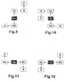
- FIG. 9 is a circuit diagram shown, in which the shift position R for engaging a reverse gear and the shift position D for the engagement of a forward gear with respect to the basic position X are arranged point-symmetrical. Next, the in FIG. 9 shown circuit diagram a switching position P for the insertion of a parking brake. Overall, this results in a staircase-shaped course of the individual switching positions.
- FIG. 10 shown circuit diagram is with the exception of the arrangement of the switching position P mirror symmetry to that in FIG. 9 shown circuit diagram.
- FIGS. 11 and 12 Schematics shown are also mirror-symmetrical to each other and differ from the in FIG. 9 and FIG. 10 shown schematics, inter alia, that in the FIGS. 9 and 10 the shift position R is arranged with respect to the home position X of the selecting device in the forward direction of a vehicle in which the signal generator according to the invention is mounted, and the shift position D with respect to the basic position X of the selector in the reverse direction of the vehicle is arranged, whereas FIGS. 11 and 12 the shift position R with respect to the basic position X of the selector in the reverse direction and the shift position D with respect to the basic position X of the selector in the forward direction of travel of the vehicle is arranged.
- FIGS. 11 and 12 of the FIGS. 9 and 10 differ in that in the FIGS. 11 and 12 no switching position P is provided.
- FIGS. 9 and 10 the insertion of a drive gear D, R by deflecting the selection device is transverse to the vehicle direction.
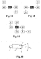
- FIGS. 13 and 14 correspond to the FIGS. 11 and 12 wherein the arrangement of the shift position R for the engagement of a reverse gear and the shift position D for the engagement of a forward gear is respectively reversed.
- FIG. 15 shows a signal generator with a deflectable in four directions selection device, which is designed so that by means of the selection device in addition to setting the operating conditions of the automatic switching device of the gear change further devices are controllable, so that the selection device can be designed as a multi-functional element.
- the circuit diagram for setting the operating states of the automatic switching device of the gear change transmission corresponds to the in FIG. 11 shown circuit diagram, in addition, a switching position P is provided for the insertion of a parking brake.
- the additional shift positions S1 and S2 serve to select additional functions of the transmission or other devices (e.g., navigation device, radio, etc.).
- the selection device of the signal generator according to the invention can be designed for example in the form of a shift lever and mounted on a center console of a vehicle (not shown).
- the selector is as in FIG. 16 shown, executed in the form of a steering column lever 1 and pivotally connected to a (not shown) steering column of a vehicle, so that the selection device can be moved in one or more steering wheel planes and in these planes perpendicular.
- the steering column lever 1 has an actuating knob 2, which at the end of a Steering rod lever rod 3 is mounted on, wherein the steering column lever rod 3 is pivotally mounted with its end, not shown, on a steering column, also not shown, of a motor vehicle.
- the steering column lever 1 serves as a selector of the signal generator according to the invention and has for this purpose at the end of the steering column lever rod 3, not shown, on electrical contacts.
- steering column lever 1 By closing the contacts in deflection of the steering column lever 1 switching commands are passed to an evaluation circuit, not shown, which controls the automatic switching device of the gear change transmission and optionally other devices.
- the steering column lever 1 is hinged to the steering column, that he according to the diagrams of the FIGS. 1 to 15 can be deflected and moves automatically after a deflection back to its normal position.
- the in FIG. 16 shown steering column lever 1 a button 4, which is used in circuit diagrams that do not have their own shift position for the insertion of a parking brake, to give a command for inserting a parking brake.
- the steering column lever 1 has a reverse lock button 5, wherein the steering column lever 1 is deflected only when the reverse lock button 5 in a shift position R for engaging a reverse gear.
- the signal generator according to the invention may also be connected to a display device, not shown, which indicates the respectively activated operating state of the automatic switching device of the gear change transmission.
- FIGS. 17-31 a selection of different circuit diagrams is shown, as they can be realized with the signal generator according to the invention.
- the fields highlighted in white designate unstable positions of the selection device, ie positions in which the selection direction only lingers as long as it is held there.
- the white filed fields are marked with the letters R, N, N1, N2, D, P, S1, S2.
- R stands for a shift position for the engagement of a reverse gear
- N, N1, N2 for shift positions for the interruption of the torque transmission in the gear change
- D for a shift position for the engagement of a forward gear
- P for a shift position for the engagement of a parking brake
- S1, S2 for switching positions for first and second additional functions.
- the fields highlighted in black and marked X symbolize the respective stable basic position of the selection device, ie the respective position in one Circuit diagram in which the selection device remains when it is not deflected or to which the selection device returns after it has been deflected into an unstable position.
- the arrows in the FIGS. 17-31 indicate the directions in which the selector can be deflected from a respective position.
- FIGS. 17-22 show circuit diagrams, as can be realized with a signal generator, the selector is deflected in only three directions
- Particularly advantageous to signalers with deflectable in three directions selection device is in addition to the simple structure of the selector of the small footprint of the feasible circuit diagrams.
- FIG. 17 shows a possible circuit diagram according to a first preferred embodiment of a switch according to the invention, in which the selection means for selecting the switching position N for the interruption of the torque transmission in the gear change transmission starting from the basic position X is deflected in a first direction, and for selecting the switching position R for the insertion a reverse gear starting from the switching position N is first deflected in a second direction, wherein the second direction is not opposite to the first direction and different from the first direction, and after deflection in the second direction is deflected back into the first direction.
- the selection device for selecting the shift position R for the engagement of a reverse gear starting from the shift position N overall a step-shaped course of the deflection movement.
- the first direction shown may be, for example, a direction toward an operator of the selection device (driver side), and in the second direction, a forward travel direction of a vehicle in which the signal generator according to the invention is mounted.
- the selector For selecting the shift position D for engagement of a forward gear, the selector is first deflected from the shift position N into a third direction which is a direction different from the first of the second direction and not a direction opposite to the first direction, and after deflection in the third direction again deflected in the first direction.
- a third direction which is a direction different from the first of the second direction and not a direction opposite to the first direction
- the selection device for Selecting the shift position D for the engagement of a forward gear starting from the shift position N in turn, an overall step-shaped course of the deflection movement.
- FIG. 17 shown circuit diagram is in the third direction to the opposite direction of the second direction and thus oriented in the reverse direction of the vehicle direction.
- the deflection of the selection device between the individual switching positions N and R or N and D is preferably carried out without a break by a single continuous step-shaped deflection movement of the selection device.
- FIG. 17 shown circuit diagram A particularly preferred embodiment of the in FIG. 17 shown circuit diagram is in FIG. 18 shown.
- FIG. 18 differs from FIG. 17 in that, by means of the selection device of the signal generator according to the invention, in addition to setting the operating states of the automatic shifting device of the gear change transmission, further devices can be controlled or additional functions can be selected.
- the selection device additionally a first switching position S1 for a first additional function and a second switching position S2 for a second additional function selectable, wherein the selection means for selecting the switching position S1 starting from the basic position X is deflected in a direction equal to the second Direction of FIG. 17 and thus equal to the forward direction of travel of the vehicle.
- the selection device is deflected starting from the basic position X in a direction which is equal to the third direction of FIG. 17 and thus equal to the reverse direction.
- the shift positions S1 and S2 can be used, for example, for manually switching the gear change transmission, but also for operating a navigation system, a chassis control, an air conditioner or control of any other device.
- FIG. 17 alternative embodiment is in FIG. 19 shown.
- FIG. 19 The diagram shown differs from that in FIG. 17 shown circuit diagram basically in that two switching positions N1, N2 for the Interruption of torque transmission are provided in the gear change transmission.
- the selection device can be deflected starting from the basic position X in a first or second direction, the first direction being unequal to the second direction.
- the second direction is the opposite direction to the first direction.
- the selection device is initially deflectable starting from the switching position N1 in a third direction, which is different from the first and second directions and no opposite direction to the first and second directions, and after deflection in the third direction again into the first or second direction second direction deflectable.
- the selection device For selecting the shift position D, the selection device is initially deflectable starting from the shift position N2 in a direction which is likewise equal to the third direction, and can be deflected back into the first or second direction after deflection in the third direction.
- the selection device for selecting the shift position D for the engagement of a forward gear, starting from the shift position N2 there is again an overall step-shaped course of the deflection movement.
- FIG. 20 a schematic diagram is shown that differs from the one in FIG. 17 distinguished switching diagram characterized in that by means of the selection device additionally a shift position P is selected for the insertion of a parking brake, wherein the selection means for selecting the shift position P starting from the shift position R first in the second direction of FIG. 17 and thus in the forward direction of travel of the vehicle is deflectable, and deflected after deflection in the second direction in a direction which is equal to the first direction of FIG. 17 and is thus oriented towards an operator of the selection device (driver side).
- the selection device for selecting the shift position P for the insertion of a parking brake starting from the shift position R overall a step-shaped course of the deflection movement.
- FIG. 21 shows a modification of the in FIG. 19 Shown diagram, the analog to
- FIG. 20 has a shift position P for the insertion of a parking brake.
- FIG. 22 is shown a circuit diagram, starting from the basic position X by deflecting the selector in a direction associated with FIG. 19 has been referred to as "third direction", directly permitting selection of the shift position P.
- third direction directly permitting selection of the shift position P.
- FIGS. 23-31 show circuit diagrams, as they can be realized with a signal generator according to the invention, the selector is deflected in four directions. This allows a significant increase in the number of feasible circuit diagrams.
- FIG. 23 The diagram shows the related diagram FIG. 17 and differs therefrom in that the selection device for selecting the switching position P can be deflected starting from the basic position X in a fourth direction, which differs from that in connection with FIG FIG. 17 described first, second and third directions is different.
- the fourth direction corresponds to deflecting the selector away from an operator of the selector and thus towards the passenger side.
- FIG. 24 is that related to FIG. 19 described circuit diagram picked up again, the in FIG. 24 shown circuit diagram analogous to FIG. 23 additionally one from the. Basic position X directly accessible switching position P for inserting a parking brake.
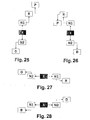
- FIG. 25 is a circuit diagram shown, in which the shift position R for engaging a reverse gear and the shift position D for the engagement of a forward gear with respect to the basic position X are arranged point-symmetrical. Next, the in FIG. 25 shown circuit diagram a switching position P for the insertion of a parking brake. Overall, this results in a stepped arrangement of the individual switching positions of the selection device.
- FIG. 26 shown circuit diagram is with the exception of the arrangement of the switching position P mirror symmetry to that in FIG. 25 shown circuit diagram.
- FIGS. 27 and 28 Schematics shown are also mirror-symmetrical to each other and differ from the in FIG. 25 and FIG. 26 shown schematics, inter alia, that in the FIGS. 25 and 26 the shift position R is arranged with respect to the home position X of the selecting device in the forward direction of a vehicle in which the signal generator according to the invention is mounted, and the shift position D with respect to the basic position X of the selector in the reverse direction of the vehicle is arranged, whereas FIGS. 27 and 28 the shift position R with respect to the basic position X of the selector in the reverse direction and the shift position D with respect to the basic position X of the selector in the forward direction of travel of the vehicle is arranged.
- FIGS. 27 and 28 of the FIGS. 25 and 26 differ in that in the FIGS. 27 and 28 no switching position P is provided.
- the basic deflection direction of the selection device between the individual switching positions N1, N2, R, P, D is not the same as in FIGS FIGS. 25 and 26 in the vehicle longitudinal direction, but is oriented in the vehicle transverse direction.
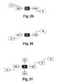
- FIGS. 29 and 30 correspond to the FIGS. 27 and 28 wherein the arrangement of the shift position R for the engagement of a reverse gear and the shift position D for the engagement of a forward gear is respectively reversed.
- FIG. 31 shows a signal generator with a deflectable in four directions selection device, which is designed so that by means of the selection device in addition to setting the operating conditions of the automatic switching device of the gear change further devices are controllable, so that the selection device can be designed as a multi-functional element.
- the circuit diagram for setting the operating states of the automatic switching device of the gear change transmission corresponds to the in FIG. 27 shown circuit diagram, in addition, a switching position P is provided for the insertion of a parking brake.
- the additional shift positions S1 and S2 serve to select additional functions of the transmission or to operate other devices (e.g., navigation device, radio, etc.).
- the selection device of the signal generator according to the invention can for example be designed in the form of a shift lever and attached to a center console of a vehicle.
- the selection device is designed in the form of a steering column lever and articulated to a steering column of a vehicle, so that the selection device can be moved in one or more steering wheel planes and in planes perpendicular thereto.
- the steering column lever has an operating knob which is attached to one end of a steering column lever rod, wherein the steering column lever rod is pivotally attached at its other end to the steering column of the motor vehicle.
- the steering column lever serves as a selector of the signal generator according to the invention and has for this purpose at its end connected to the steering column end of the steering column lever rod electrical contacts. By closing the contacts upon deflection of the steering column lever switching commands are passed to an evaluation circuit that controls the automatic switching device of the gear change transmission and optionally other devices.
- the steering column lever is hinged to the steering column, that he according to the circuit diagrams of the FIGS. 17 to 31 can be deflected and moves automatically after a deflection back to its normal position.
- the steering column lever preferably has a button which, in the case of circuit diagrams which do not have their own shift position for the engagement of a parking brake, serves to issue a command for engaging a parking brake.
- the steering column lever preferably has a reverse lock button, wherein the steering column lever is deflected only with the reverse lock button pressed in a shift position R for engaging a reverse gear.
- the signal generator according to the invention may also be connected to a display device which indicates the respectively activated operating state of the automatic switching device of the gear change transmission.
Abstract
Description
Die vorliegende Erfindung betrifft einen Signalgeber zum Einstellen der Betriebszustände einer selbsttätigen Schaltvorrichtung eines Gangwechselgetriebes mit einer sich mindestens für bestimmte Schaltpositionen selbständig in eine Grundstellung zurückstellenden Auswahleinrichtung.The present invention relates to a signal generator for setting the operating states of an automatic switching device of a gear change transmission with a selector device that at least for certain switching positions automatically returns to a basic position.
Insbesondere im Kraftfahrzeugbau finden Gangwechselgetriebe mit selbsttätiger Schaltvorrichtung in hohem Maße Verwendung. Derartige Schaltvorrichtungen weisen üblicherweise einen Betriebszustand R für das Einlegen des wenigstens einen Rückwärtsganges, einen Betriebszustand N für die Unterbrechung der Drehmomentübertragung im Gangwechselgetriebe und einen Betriebszustand D für das Einlegen eines Vorwärtsganges auf. Häufig ist zusätzlich einen Betriebszustand P für das Einlegen einer Parkbremse vorgesehen.In particular, in the automotive industry find change gear with automatic switching device in a high degree of use. Such switching devices usually have an operating state R for the engagement of the at least one reverse gear, an operating state N for the interruption of the torque transmission in the gear change transmission and an operating state D for the engagement of a forward gear. Frequently, an operating state P is additionally provided for inserting a parking brake.
Ist beispielsweise der Betriebszustand D für das Einlegen eines Vorwärtsganges aktiviert, so wählt die selbsttätige Schaltvorrichtung des Gangwechselgetriebes aus den zur Verfügung stehenden Vorwärtsgängen in Abhängigkeit von bestimmten Fahrzeugparametern wie z. B. der momentanen Geschwindigkeit oder der Beschleunigung automatisch entsprechend einem oder mehreren vorgegebenen Schaltprogrammen den am geeignetsten erscheinenden Vorwärtsgang aus und steuert das Gangwechselgetriebe entsprechend. Häufig sind durch den Fahrer des Fahrzeugs für Sommer und Winter und / oder sportliches Fahren und sparsames Fahren eigene Schaltprogramme auswählbar. Gesteuert werden derartige Schaltvorrichtungen über Signalgeber. Während die Steuerung durch den Signalgeber früher mechanisch über Seilzüge erfolgte, wird heute eine elektronische Übertragung der Signale bevorzugt, da dies eine flexiblere Anordnung des Signalgebers erlaubt. Zur Auswahl des jeweiligen Betriebszustandes R N D P der selbsttätigen Schaltvorrichtung weist ein solcher Signalgeber einen üblicherweise an einer Mittelkonsole des Fahrzeugs vorgesehenen Schalthebel auf. Die den einzelnen Betriebszuständen entsprechenden Funktionen des Schalthebels sind in der Regel in Längsrichtung des Fahrzeugs linear angeordnet und können durch eine Bewegung des Schalthebels in Längsrichtung des Fahrzeugs ausgewählt werden. Bei konventionellen Signalgebern gilt eine Funktion nur so lange als ausgewählt, so lange sich der Schalthebel an der die jeweilige Funktion bezeichnenden Position befindet.If, for example, the operating state D is activated for the engagement of a forward gear, then the automatic shifting device of the gear change transmission selects from the available forward gears as a function of certain vehicle parameters, such as vehicle speed. B. the current speed or acceleration automatically according to one or more predetermined switching programs from the most appropriate appearing forward gear and controls the gear change accordingly. Frequently, the driver of the vehicle can select his own shift programs for summer and winter and / or sporty driving and economical driving. Such switching devices are controlled via signal generator. Whereas control by the signal generator used to be effected mechanically by means of cables, electronic transmission of the signals is preferred today, since this allows a more flexible arrangement of the signal generator. For selecting the respective operating state RNDP of the automatic switching device, such a signal generator has a switching lever usually provided on a center console of the vehicle. The functions of the shift lever corresponding to the individual operating conditions are generally arranged linearly in the longitudinal direction of the vehicle and can be selected by a movement of the shift lever in the longitudinal direction of the vehicle. In conventional signalers, a function is only selected as long as the shift lever is located at the position indicating the respective function.
Ein entsprechender Signalgeber ist in der
Dazu ist erforderlich, dass die selbsttätige Schaltvorrichtung des Gangwechselgetriebes in Form eines elektronischen Steuergerätes ausgebildet ist, und der Schalthebel des Signalgebers über zugeordnete elektrische Kontakte ein jeweiliges Steuersignal an das elektronische Steuergerät abgibt.For this purpose, it is necessary that the automatic switching device of the gear change transmission is designed in the form of an electronic control unit, and the switching lever of the signal generator emits a respective control signal to the electronic control unit via associated electrical contacts.
In den letzten Jahren gibt es zudem Bestrebungen, den an der Mittelkonsole angeordneten Schalthebel des Signalgebers durch einen an der Lenksäule befestigten Wählhebel zu ersetzen, um beispielsweise eine größere Freiheit bei der Innenraumgestaltung des Fahrzeugs zu erlangen.In recent years, there are also efforts to replace the arranged on the center console shifter of the signal generator by a mounted on the steering column selector lever, for example, to gain greater freedom in the interior design of the vehicle.
Ein Signalgeber mit einem solchen Wählhebel ist in der
Auch hier erfolgt die Steuerung der selbsttätigen Schaltvorrichtung des automatisch geschalteten Getriebes über Impulse, die der Signalgeber entsprechend der Bewegung des Wählhebels abgibt, so dass der Wählhebel nach Auswahl einer Funktion in seine Ausgangslage zurückkehren kann.Again, the control of the automatic switching device of the automatically switched transmission via pulses, which emits the signal generator according to the movement of the selector lever, so that the selector lever can return to its original position after selecting a function.
Nachteilig an den bekannten Signalgebern zum Einstellen der Betriebszustände einer selbsttätigen Schaltvorrichtung eines Gangwechselgetriebes mit einer sich mindestens für bestimmte Schaltpositionen selbständig in eine Grundstellung zurückstellenden Auswahleinrichtung ist, dass beispielsweise durch unbeabsichtigtes Überreißen einer ersten Position (bzw. der Ausgangslage) der Auswahleinrichtung versehentlich ein nicht beabsichtigter Betriebszustand ausgewählt werden kann.A disadvantage of the known signal generator for setting the operating states of an automatic switching device of a gear change with a self-resetting at least for certain switching positions selection device is that, for example, by unintentional tearing a first position (or the initial position) of the selector accidentally unintentional operating condition can be selected.
Weiterhin ist aus der gattungsgemaßen
Es ist Aufgabe der vorliegenden Erfindung, einen Signalgeber zum Einstellen der Betriebszustände einer selbsttätigen Schaltvorrichtung eines Gangwechselgetriebes zur Verfügung zu stellen, der eine unbeabsichtigte Auswahl eines Betriebszuständes wirkungsvoll vermeidet und dem Fahrer ein intuitives Schalten ermöglicht.It is an object of the present invention to provide a signal generator for adjusting the operating states of an automatic shifting device of a gear change transmission, which effectively avoids an unintentional selection of an operating state and allows the driver an intuitive shifting.
Die Aufgabe wird gemäß dem Hauptanspruch der Erfindung gelöst.The object is achieved according to the main claim of the invention.
Die Erfindung wird in ihren Unteransprüchen weitergebildet.The invention is further developed in its subclaims.
Gemäß einem ersten bevorzugten Ausführungsbeispiel der vorliegenden Erfindung weist ein Signalgeber zum Einstellen der Betriebszustände einer selbsttätigen Schaltvorrichtung eines Gangwechselgetriebes eine in wenigstens drei Richtungen auslenkbare, sich mindestens für bestimmte Schaltpositionen selbsttätig in eine Grundstellung zurückstellende Auswahleinrichtung auf, mittels der zumindest eine Schaltposition für das Einlegen eines Rückwärtsganges, eine Schaltposition für die Unterbrechung der Drehmomentübertragung im Gangwechselgetriebe und eine Schaltposition für das Einlegen eines Vorwärtsganges auswählbar ist, wobei die Auswahleinrichtung zum Auswählen der Schaltposition für die Unterbrechung der Drehmomentübertragung im Gangwechselgetriebe ausgehend von der Grundstellung in eine erste Richtung auslenkbar ist und die Auswahleinrichtung zum Auswählen einer der weiteren Schaltpositionen ausgehend von der Schaltposition für die Unterbrechung der Drehmomentübertragung im Gangwechselgetriebe jeweils in eine weitere von der ersten Richtung verschiedene Richtung auslenkbar ist, die keine Gegenrichtung der ersten Richtung ist.According to a first preferred embodiment of the present invention, a signal generator for setting the operating states of an automatic shift device of a gear change a deflectable in at least three directions, at least for certain shift positions automatically returning to a basic position selection means, by means of at least one shift position for engaging a reverse gear a shift position for interrupting torque transmission in the speed change gear and a shift position for engaging a forward gear is selectable, wherein the selection means for selecting the shift position for the interruption of the torque transmission in the gear change transmission from the basic position is deflected in a first direction and the selection device for selecting one of the other switching positions starting from the switching position for the interruption of the torque transmission in the gear change gear in each case in a further direction different from the first direction is deflected, which is not a reverse direction of the first direction.
Zum Auswählen der antriebsübertragenden Betriebszustände der selbsttätigen Schaltvorrichtung des Gangwechselgetriebes ist es somit erforderlich, die Auswahleinrichtung aus einer stabilen Grundstellung zunächst durch Auslenken in eine erste Auslenkrichtung in eine instabile Schaltposition für die Unterbrechung der Drehmomentübertragung im Gangwechselgetriebe zu bringen, und anschließend durch Auslenken in eine weitere, von der ersten Auslenkrichtung verschiedenen Richtung in eine weitere instabile Schaltposition (z.B. zum Einlegen eines Vorwärtsganges) zu bringen.To select the drive-transmitting operating states of the automatic shift device of the gear change transmission, it is thus necessary to first bring the selection device from a stable basic position by deflecting in a first deflection direction into an unstable shift position for the interruption of the torque transmission in the gear change transmission, and then by deflecting in another, to bring from the first direction of deflection different direction in another unstable switching position (eg to engage a forward gear).
Dabei darf die weitere Auslenkrichtung keine Gegenrichtung zur ersten Auslenkrichtung sein, da sonst wiederum die Grundstellung erreicht würde. Somit muß beim Schalten des erfindungsgemäßen Signalgebers zwischen einzelnen Schaltpositionen immer die Auslenkrichtung der Auswahleinrichtung geändert werden, so dass ein unbeabsichtigtes "Durchschalten" der einzelnen Schaltpositionen wirkungsvoll vermieden und intuitives Schalten möglich wird.The further deflection direction must not be an opposite direction to the first deflection direction, since otherwise the basic position would be reached again. Thus, when switching the signal generator according to the invention between individual switching positions always the deflection of the selector must be changed so that an unintentional "switching through" the individual switching positions effectively avoided and intuitive switching is possible.
Da die antriebsübertragenden Betriebszustände zudem immer über die Schaltposition für die Unterbrechung der Drehmomentübertragung im Gangwechselgetriebe (Leerlauf) geschaltet werden, wird die Gefahr einer Beschädigung des Gangwechselgetriebes durch Fehlbedienung der Auswahleinrichtung unabhängig von einer ggf. zusätzlich vorhandenen elektronischen Sicherungsschaltung weiter verringert.In addition, since the drive-transmitting operating states are always switched via the shift position for the interruption of the torque transmission in the gear change transmission (idling), the risk of damage to the gear change transmission by incorrect operation of the selection device is further reduced regardless of an optionally present electronic fuse circuit.
Nach dem Auslenken der Auswahleinrichtung kehrt diese selbsttätig in ihre Grundstellung zurück, so dass die Bedienung der Auswahleinrichtung von dem aktivierten Betriebszustand der selbsttätigen Schaltvorrichtung des Gangwechselgetriebes entkoppelt ist.After deflecting the selection device, this automatically returns to its normal position, so that the operation of the selection device is decoupled from the activated operating state of the automatic shifting device of the gear change transmission.
In einer ersten bevorzugten Ausführungsform ist die Auswahleinrichtung zum Auswählen der Schaltposition für das Einlegen eines Rückwärtsganges ausgehend von der Schaltposition für die Unterbrechung der Drehmomentübertragung im Gangwechselgetriebe in eine zweite Richtung auslenkbar, die keine Gegenrichtung zu der ersten Richtung und von der ersten Richtung verschieden ist, und ist die Auswahleinrichtung zum Auswählen der Schaltposition für das Einlegen eines Vorwärtsganges ausgehend von der Schaltposition für die Unterbrechung der Drehmomentübertragung im Gangwechselgetriebe in eine dritte Richtung auslenkbar, die eine von der ersten und der zweiten Richtung verschiedene Richtung und keine Gegenrichtung zu der ersten Richtung ist.In a first preferred embodiment, the selection means for selecting the shift position for the engagement of a reverse gear from the shift position for the interruption of the torque transmission in the gear change transmission is deflectable in a second direction, which is not opposite to the first direction and from the first direction, and For example, the selecting means for selecting the shift position for engaging a forward gear from the torque-transmission interrupting shift position in the speed change gear is deflectable in a third direction which is a direction different from the first and second directions and not an opposite direction to the first direction.
Dieses Schaltschema erlaubt unter anderem eine lineare Anordnung der Schaltpositionen für das Einlegen eines Rückwärtsganges, für die Unterbrechung der Drehmomentübertragung im Gangwechselgetriebe und für das Einlegen eines Vorwärtsganges und somit einen platzsparenden Aufbau der Auswahleinrichtung des Signalgebers.This shift pattern allows, inter alia, a linear arrangement of the shift positions for engaging a reverse gear, for the interruption of torque transmission in the gear change transmission and for engaging a forward gear and thus a space-saving design of the selector of the signal generator.
Vorzugsweise ist der Signalgeber so ausgebildet, dass mittels der Auswahleinrichtung zusätzlich zum Einstellen der Betriebszustände der selbsttätigen Schaltvorrichtung des Gangwechselgetriebes weitere Vorrichtungen steuerbar sind.Preferably, the signal generator is designed so that by means of the selection device in addition to setting the operating states of the automatic switching device of the gear change mechanism further devices are controllable.
Dadurch ist es erfindungsgemäß möglich, die Auswahleinrichtung des Signalgebers als Multifunktionsschaltelement auszuführen und zusätzlich beispielsweise Einstellungen einer Fahrwerksregelung, einer Klimaanlage, eines Navigationssystems oder Radios vorzunehmen. Hierdurch kann die Anzahl der für die Bedienung der jeweiligen Vorrichtungen benötigten Auswahleinrichtungen reduziert werden.This makes it possible according to the invention to carry out the selection device of the signal generator as a multi-functional switching element and additionally make, for example, settings of a suspension control system, an air conditioning system, a navigation system or radios. In this way, the number of required for the operation of the respective devices selection means can be reduced.
Erfindungsgemäß ist es besonders vorteilhaft, wenn mittels der Auswahleinrichtung zusätzlich eine Schaltposition für eine erste zusätzliche Funktion und eine Schaltposition für eine zweite zusätzliche Funktion auswählbar ist, wobei die Auswahleinrichtung zum Auswählen der Schaltposition für eine erste zusätzliche Funktion ausgehend von der Grundstellung in eine Richtung auslenkbar ist, die gleich der zweiten Richtung ist, und die Auswahleinrichtung zum Auswählen der Schaltposition für eine zweite zusätzliche Funktion ausgehend von der Grundstellung in eine Richtung auslenkbar ist, die gleich der dritten Richtung ist.According to the invention, it is particularly advantageous if, by means of the selection device, additionally a shift position for a first additional function and a shift position for a second additional function can be selected, wherein the selection device for selecting the shift position for a first additional function can be deflected from the basic position in one direction , which is equal to the second direction, and the selecting means for selecting the switching position for a second additional function is deflectable from the home position in a direction equal to the third direction.
Dies erlaubt eine direkte Steuerung der weiteren Vorrichtungen eines Fahrzeugs, wobei ein unbeabsichtigtes Auswählen der Betriebszustände der selbsttätigen Schaltvorrichtung des Gangwechselgetriebes weiterhin verhindert wird.This allows a direct control of the other devices of a vehicle, wherein an unintentional selection of the operating conditions of the automatic switching device of the gear change transmission is further prevented.
Gemäß einer zweiten bevorzugten Ausführungsform sind eine erste und eine zweite Schaltposition für die Unterbrechung der Drehmomentübertragung im Gangwechselgetriebe vorgesehen, wobei die Auswahleinrichtung zum Auswählen der - ersten oder-der zweiten Schaltposition für die Unterbrechung der Drehmomentübertragung im Gangwechselgetriebe ausgehend von der Grundstellung in eine erste und zweite Richtung auslenkbar ist, wobei die erste Richtung ungleich der zweiten Richtung ist, und ist die Auswahleinrichtung zum Auswählen der Schaltposition für das Einlegen eines Rückwärtsganges ausgehend von der ersten Schaltposition für die Unterbrechung der Drehmomentübertragung im Gangwechselgetriebe in eine dritte Richtung auslenkbar, die verschieden von der ersten und zweiten Richtung und keine Gegenrichtung zu der ersten und zweiten Richtung ist, und ist die Auswahleinrichtung zum Auswählen der Schaltposition für das Einlegen eines Vorwärtsganges ausgehend von der zweiten Schaltposition für die Unterbrechung der Drehmomentübertragung im Gangwechselgetriebe in eine Richtung auslenkbar, die gleich der dritten Richtung ist.According to a second preferred embodiment, a first and a second shift position for the interruption of the torque transmission in the speed change gear are provided, wherein the selecting means for selecting the - first or the second switching position for the interruption of the torque transmission in the gear change transmission starting from the basic position into a first and second Direction is deflected, wherein the first direction is different from the second direction, and the selection means for selecting the shift position for the engagement of a reverse gear starting from the first switching position for the interruption of the torque transmission in the gear change transmission in a third direction, unlike the first deflected and the second direction and not the opposite direction to the first and second directions, and is the selecting means for selecting the shift position for engaging a forward gear from the second one Shift position for the interruption of the torque transmission in the gear change transmission in a direction deflectable, which is equal to the third direction.
Durch das Vorsehen von zwei Schaltpositionen für die Unterbrechung der Drehmomentübertragung im Gangwechselgetriebe ist es möglich, die Anzahl der mit dem erfindungsgemäßen Signalgeber realisierbaren Schaltbilder erheblich zu erhöhen. Weiter kann das Risiko von Fehlbedienungen weiter reduziert werden, da ein Benutzer bereits vor der Auswahl einer Schaltposition für die Unterbrechung der Drehmomentübertragung im Gangwechselgetriebe entscheiden muß, ob er eine Schaltposition zum Einlegen einer Vorwärts oder Rückwärtsganges erreichen möchte.By providing two switching positions for the interruption of the torque transmission in the gear change transmission, it is possible to increase the number of realizable with the signal generator according to the invention circuit diagrams considerably. Further, the risk of erroneous operations can be further reduced because a user must decide before selecting a shift position for the interruption of torque transmission in the gear change transmission, whether he wants to achieve a shift position for engaging a forward or reverse gear.
Besonders vorteilhaft ist es, wenn mittels der Auswahlrichtung zusätzlich eine Schaltposition für das Einlegen einer Parkbremse auswählbar ist, da so mittels der Auswahleinrichtungen alle typischen Betriebszustände einer selbsttätigen Schaltvorrichtung eines Gangwechselgetriebes ausgewählt werden können.It is particularly advantageous if, by means of the selection direction, a shift position for the engagement of a parking brake can also be selected, since in this way all typical operating states of an automatic shift device of a gear change transmission can be selected by means of the selection devices.
Vorzugsweise ist die Auswahleinrichtung zum Auswählen der Schaltposition für das Einlegen einer Parkbremse ausgehend von der Schaltposition für das Einlegen eines Rückwärtsganges in eine Richtung auslenkbar, die gleich der ersten Richtung ist.Preferably, the selecting means for selecting the shift position for engaging a parking brake is deflectable from the shift position for engagement of a reverse gear in a direction equal to the first direction.
Dadurch ist es zum einen gewährleistet, dass zum Einlegen einer Parkbremse ausgehend vom der Schaltposition für das Einlegen des Rückwärtsganges eine weitere Änderung der Auslenkrichtung der Auswahleinrichtung erforderlich ist, wodurch ein unbeabsichtigtes Einlegen der Parkbremse vermieden werden kann. Zum anderen ist es so möglich, die bei traditionellen Auswahleinrichtungen für den Betriebszustand eines Automatikgetriebes gebräuchliche Reihenfolge der Schaltpositionen, bei der die Schaltposition für das Einlegen einer Parkbremse und die Schaltposition für das Einlegen eines Rückwärtsganges benachbart sind, beizubehalten.This ensures on the one hand that for inserting a parking brake, starting from the shift position for engagement of the reverse gear, a further change of the deflection of the selection device is required, whereby an accidental insertion of the parking brake can be avoided. On the other hand, it is thus possible to maintain the order of shift positions commonly used in traditional automatic transmission selector devices in which the shift position for the parking brake and the shift position for the reverse gear shift are adjacent.
Alternativ kann die Auswahleinrichtung zum Auswählen der Schaltposition für das Einlegen einer Parkbremse ausgehend von der Grundstellung in einer Richtung auslenkbar sein, die gleich der dritten Richtung ist.Alternatively, the selecting means for selecting the shift position for engaging a parking brake may be deflected from the home position in a direction equal to the third direction.
Dies erlaubt ein direktes Einlegen der Parkbremse ausgehend von der Grundeinstellung.This allows a direct engagement of the parking brake starting from the default setting.
Gemäß einem zweiten bevorzugten Ausführungsbeispiel ist die Auswahleinrichtung in vier Richtungen auslenkbar.According to a second preferred embodiment, the selection device is deflectable in four directions.
Dies erlaubt eine weitere Erhöhung der Zahl der mit dem erfindungsgemäßen Signalgeber realisierbaren Schaltbilder der Auswahleinrichtung.This allows a further increase in the number of circuit diagrams of the selection device that can be realized with the signal generator according to the invention.
In diesem zweiten Ausführungsbeispiel ist die Auswahleinrichtung zum Auswählen der Schaltposition für das Einlegen einer Parkbremse vorzugsweise ausgehend von der Grundstellung in eine vierte Richtung auslenkbar, die verschieden von der im vorangegangenen beschriebenen ersten, zweiten und dritten Richtung ist.In this second exemplary embodiment, the selection device for selecting the shift position for engaging a parking brake is preferably deflectable starting from the basic position in a fourth direction, which is different from the first, second and third directions described in the preceding.
Somit ist es wiederum möglich, die Schaltposition für das Einlegen einer Parkbremse ausgehend von der Grundstellung direkt zu erreichen.Thus, it is again possible to reach the switching position for the insertion of a parking brake starting from the basic position directly.
Gemäß einer bevorzugten Ausführungsform des zweiten Ausführungsbeispiels sind eine erste und eine zweite Schaltposition für die Unterbrechung der Drehmomentübertragung im Gangwechselgetriebe vorgesehen, wobei die Auswahleinrichtung zum Auswählen der ersten oder der zweiten Schaltposition für die Unterbrechung der Drehmomentübertragung im Gangwechselgetriebe ausgehend von der Grundstellung in eine erste oder zweite Richtung auslenkbar ist, wobei die erste Richtung-ungleich der zweiten Richtung ist, und ist die Auswahleinrichtung zum Auswählen der Schaltposition für das Einlegen eines Rückwärtsganges ausgehend von der ersten Schaltposition für die Unterbrechung der Drehmomentübertragung im Gangwechselgetriebe in eine dritte Richtung auslenkbar, die verschieden von der ersten und zweiten Richtung und keine Gegenrichtung zu der ersten und zweiten Richtung ist, und ist die Auswahleinrichtung zum Auswählen der Schaltposition für das Einlegen eines Vorwärtsganges ausgehend von der zweiten Schaltposition für die Unterbrechung der Drehmomentübertragung im Gangwechselgetriebe in eine vierte Richtung auslenkbar, die verschieden von der ersten,According to a preferred embodiment of the second embodiment, a first and a second shift position for the interruption of torque transmission are provided in the gear change transmission, wherein the selection means for selecting the first or the second shift position for the interruption of torque transmission in the gear change transmission starting from the basic position in a first or second Direction is deflected, wherein the first direction is different from the second direction, and the selection means for selecting the shift position for the engagement of a reverse gear starting from the first switching position for the interruption of the torque transmission in the speed change gearbox in a third direction, unlike the is the first and second direction and no opposite direction to the first and second directions, and is the selection means for selecting the shift position for engaging a forward gear starting from v on the second shift position for the interruption of the torque transmission in the gear change transmission in a fourth direction, which is different from the first,
zweiten und dritten Richtung und keine Gegenrichtung zur ersten und zweiten Richtung ist.second and third direction and no opposite direction to the first and second directions.
Auf diese Weise lassen sich Schaltungsanordnungen realisieren, bei denen die Schaltposition für das Einlegen eines Rückwärtsganges und die Schaltposition für das Einlegen eines Vorwärtsganges in Bezug auf die Grundstellung der Auswahleinrichtung punktsymmetrisch angeordnet sind und sich somit gegenüber liegen, wodurch eine intuitive Bedienung der Auswahleinrichtung des erfindungsgemäßen Signalgebers zusätzlich erleichtert wird.In this way, circuit arrangements can be realized in which the shift position for engaging a reverse gear and the shift position for engaging a forward gear with respect to the basic position of the selector are arranged point-symmetrically and are thus opposite, creating an intuitive operation of the selector of the signal generator according to the invention is additionally facilitated.
Vorzugsweise ist auch gemäß dem zweiten Ausführungsbeispiel eine Schaltposition für das Einlegen einer Parkbremse auswählbar, wobei zum Auswählen der Schaltposition für das Einlegen einer Parkbremse die Auswahleinrichtung ausgehend von der Schaltposition für das Einlegen eines Rückwärtsganges in eine Richtung auslenkbar ist, die gleich der vorgenannten ersten oder zweiten Richtung ist.Preferably, according to the second embodiment, a shift position for the engagement of a parking brake is selectable, wherein for selecting the shift position for the insertion of a parking brake, the selection device is deflected starting from the shift position for engaging a reverse gear in a direction equal to the aforementioned first or second Direction is.
Weiter ist es auch gemäß dem zweiten Ausführungsbeispiel besonders vorteilhaft, wenn mittels der Auswahleinrichtung zusätzlich eine Schaltposition für eine erste zusätzliche Funktion und eine Schaltposition für eine zweite zusätzliche Funktion auswählbar ist, und die Auswahleinrichtung zum Auswählen der Schaltposition für eine erste zusätzliche Funktion ausgehend von der Grundstellung in eine Richtung auslenkbar ist, die gleich der dritten Richtung ist, und die Auswahleinrichtung zum Auswählen der Schaltposition für eine zweite zusätzliche Funktion ausgehend von der Grundstellung in eine Richtung auslenkbar ist, die gleich der vierten Richtung ist, so dass mittels der Auswahleinrichtung des erfindungsgemäßen Signalgebers zusätzliche Vorrichtungen steuerbar sind.Furthermore, according to the second exemplary embodiment, it is also particularly advantageous if, by means of the selection device, a switching position for a first additional function and a switching position for a second additional function can additionally be selected, and the selection device for selecting the switching position for a first additional function starting from the basic position is deflectable in a direction which is equal to the third direction, and the selection means for selecting the switching position for a second additional function is deflected starting from the basic position in a direction which is equal to the fourth direction, so that by means of the selection device of the signal generator according to the invention additional devices are controllable.
In einer alternativen Ausführungsform weist der erfindungsgemäße Signalgeber zusätzlich eine Parktaste auf, wobei durch Drücken der Parktaste eine Parkbremse einlegbar ist.In an alternative embodiment, the signal generator according to the invention additionally has a parking key, wherein a parking brake can be inserted by pressing the parking key.
Durch das Vorsehen einer Parktaste ist es nicht nötig, eine eigene Schaltposition für das Einlegen der Parkbremse für die Auswahleinrichtung auszubilden, wodurch das Schaltbild der Auswahleinrichtung vereinfacht werden kann. Weiter kann durch das Vorsehen einer separaten Parktaste das versehentliche Einlegen der Parkbremse verhindert werden. Vorzugsweise ist die Parktaste an der Auswahleinrichtung angeordnet.By providing a parking key, it is not necessary to form a separate switching position for the insertion of the parking brake for the selector, whereby the circuit diagram the selector can be simplified. Further, by providing a separate parking key, the accidental insertion of the parking brake can be prevented. Preferably, the parking key is arranged on the selection device.
Um das versehentliche Einlegen der Schaltposition für das Einlegen eines Rückwärtsganges beim Auslenken der Auswahleinrichtung weiter zu verhindern, ist es von Vorteil, wenn der Signalgeber zusätzlich eine Rückfahr-Sperrtaste aufweist und die Auswahleinrichtung zum Auswählen der Schaltposition für das Einlegen eines Rückwärtsganges nur bei gedrückter Rückfahr-Sperrtaste auslenkbar ist.In order to further prevent the accidental insertion of the shift position for engaging a reverse gear when deflecting the selection device, it is advantageous if the signal generator additionally has a reverse lock button and the selection device for selecting the shift position for engaging a reverse gear only while holding backward Lock button is deflectable.
Dabei ist die Rückfahr-Sperrtaste vorzugsweise an der Auswahleinrichtung angeordnet.In this case, the reverse lock key is preferably arranged on the selection device.
Bevorzugt ist der erfindungsgemäße Signalgeber in einem Fahrzeug montiert.Preferably, the signal generator according to the invention is mounted in a vehicle.
Dabei ist es von Vorteil, wenn die Schaltposition für das Einlegen eines Rückwärtsganges in Bezug auf die Grundstellung der Auswahleinrichtung in Vorwärtsfahrtrichtung des Fahrzeuges angeordnet ist, und die Schaltposition für das Einlegen eines Vorwärtsganges in Bezug auf die Grundstellung der Auswahleinrichtung in Rückwärtsfahrtrichtung des Fahrzeugs angeordnet ist, da dies der konventionellen Anordnung der entsprechenden Schaltpositionen bei einem konventionellen Schalthebel eines Automatikgetriebes entspricht.It is advantageous if the shift position for engaging a reverse gear is arranged with respect to the basic position of the selection device in the forward direction of travel of the vehicle, and the shift position for engaging a forward gear with respect to the basic position of the selection device is arranged in the reverse direction of the vehicle, since this corresponds to the conventional arrangement of the corresponding shift positions in a conventional shift lever of an automatic transmission.
Selbstverständlich ist es gemäß der vorliegenden Erfindung auch möglich, diese Anordnung zu vertauschen, so dass die Schaltposition für das Einlegen eines Rückwärtsganges in Bezug auf die Grundstellung der Auswahleinrichtung in Rückwärtsfahrtrichtung des Fahrzeuges angeordnet ist, und die Schaltposition für das Einlegen eines Vorwärtsganges in Bezug auf die Grundstellung der Auswahleinrichtung in Vorwärtsfahrtrichtung des Fahrzeuges angeordnet ist, wie es der tatsächlichen Funktionsweise der jeweiligen Schaltposition besser gerecht wird.Of course, it is also possible according to the present invention to interchange this arrangement, so that the shift position for engaging a reverse gear with respect to the basic position of the selector is arranged in the reverse direction of the vehicle, and the shift position for engaging a forward gear with respect to the Basic position of the selection device is arranged in the forward direction of travel of the vehicle, as it better meet the actual operation of the respective shift position.
Vorzugsweise ist die Auswahleinrichtung in Form eines an einer Lenksäule eines Fahrzeugs befestigten Lenkstockhebels ausgeführt, da dies eine Bedienung der Auswahleinrichtung erlaubt, ohne dass ein Fahrer die Hände vom Lenkrad nehmen muß.Preferably, the selection device is designed in the form of a steering column lever attached to a steering column of a vehicle, since this allows operation of the selection device without a driver having to take his hands off the steering wheel.
Alternativ ist es auch möglich, die Auswahleinrichtung in Form eines an der Mittelkonsole des Fahrzeugs angeordneten Schalthebels auszuführen.Alternatively, it is also possible to carry out the selection device in the form of a switching lever arranged on the center console of the vehicle.
Gemäß einem bevorzugten Ausführungsbeispiel der vorliegenden Erfindung weist ein Signalgeber zum Einstellen der Betriebszustände einer selbsttätigen Schaltvorrichtung eines Gangwechselgetriebes eine in wenigstens drei Richtungen auslenkbare, sich mindestens für bestimmte Schaltpositionen selbsttätig in eine Grundstellung zurückstellende Auswahleinrichtung auf, mittels der zumindest eine Schaltposition für das Einlegen eines Rückwärtsganges, eine Schaltposition für die Unterbrechung der Drehmomentübertragung im Gangwechselgetriebe und eine Schaltposition für das Einlegen eines Vorwärtsganges auswählbar ist, wobei die Auswahleinrichtung zum Auswählen der Schaltposition für die Unterbrechung der Drehmomentübertragung im Gangwechselgetriebe ausgehend von der Grundstellung in eine erste Richtung auslenkbar ist und die Auswahleinrichtung zum Auswählen einer der weiteren Schaltpositionen ausgehend von der Schaltposition für die Unterbrechung der Drehmomentübertragung im Gangwechselgetriebe zunächst jeweils in eine weitere von der ersten Richtung verschiedene Richtung auslenkbar ist, die keine Gegenrichtung der ersten Richtung ist, und nach Auslenkung in die jeweils weitere Richtung wieder in die erste Richtung auslenkbar ist.According to a preferred embodiment of the present invention, a signal generator for setting the operating states of an automatic shifting device of a gear change a deflectable in at least three directions, at least for certain switching positions automatically returning to a basic position selection means, by means of at least one shift position for engaging a reverse gear, a shift position for the interruption of torque transmission in the speed change gear and a shift position for engaging a forward gear is selectable, wherein the selection means for selecting the shift position for the interruption of the torque transmission in the gear change gear from the basic position is deflected in a first direction and the selection means for selecting a the other switching positions starting from the switching position for the interruption of torque transmission in Gear change gear initially in each case in a further direction different from the first direction is deflected, which is not a reverse direction of the first direction, and after deflection in the respective further direction is deflected back into the first direction.
Zum Auswählen der antriebsübertragenden Betriebszustände der selbsttätigen Schaltvorrichtung des Gangwechselgetriebes ist es somit erforderlich, die Auswahleinrichtung aus einer stabilen Grundstellung zunächst durch Auslenken in eine erste Auslenkrichtung in eine instabile Schaltposition für die Unterbrechung der Drehmomentübertragung im Gangwechselgetriebe zu bringen, und anschließend zunächst durch Auslenken in eine weitere, von der ersten Auslenkrichtung verschiedene Richtung und anschließend durch Auslenken in die erste Richtung in eine weitere instabile Schaltposition (z.B. zum Einlegen eines Vorwärtsganges) zu bringen. Dabei darf die weitere Auslenkrichtung keine Gegenrichtung zur ersten Auslenkrichtung sein, da sonst wiederum die Grundstellung erreicht würde.To select the drive-transmitting operating states of the automatic shifting device of the gear change transmission, it is thus necessary to first bring the selection device from a stable initial position by deflecting in a first deflection in an unstable shift position for the interruption of torque transmission in the gear change transmission, and then first by deflecting in another to bring the direction different from the first deflection direction and then to a further unstable shift position (eg to engage a forward gear) by deflecting in the first direction. The further deflection direction must not be an opposite direction to the first deflection direction, since otherwise the basic position would be reached again.
Somit muss bei einer Auslenkung der Auswahleinrichtung zwischen einzelnen Schaltpositionen zunächst immer die Auslenkrichtung der Auswahleinrichtung geändert werden, so dass ein Schalten des erfindungsgemäßen Signalgebers durch eine im wesentlichen stufenförmige Auslenkbewegung der Auswahleinrichtung zwischen zwei aufeinanderfolgenden Schaltpositionen erfolgt. Weiter ist die grundsätzliche Auslenkrichtung der Auswahleinrichtung zur Auswahl benachbart angeordneter Schaltpositionen vorzugsweise gleich. Folglich ist es mit dem erfindungsgemäßen Signalgeber möglich, die Auswahleinrichtung immer bis zu einem Anschlag einer Schaltposition auszulenken, so dass ein unbeabsichtigtes "Durchschalten" der einzelnen Schaltpositionen wirkungsvoll vermieden und intuitives Schalten möglich wird.Thus, in the case of a deflection of the selection device between individual switching positions, the deflection direction of the selection device must first always be changed be switched so that switching of the signal generator according to the invention by a substantially step-shaped deflection movement of the selector between two successive switching positions. Furthermore, the basic deflection direction of the selection device for selecting adjacently arranged switching positions is preferably the same. Consequently, it is possible with the signal generator according to the invention to deflect the selector always up to a stop of a switching position, so that an unintentional "switching through" the individual switching positions effectively avoided and intuitive switching is possible.
Da die antriebsübertragenden Betriebszustände zudem immer über die Schaltposition für die Unterbrechung der Drehmomentübertragung im Gangwechselgetriebe (Leerlauf) geschaltet werden, wird die Gefahr einer Beschädigung des Gangwechselgetriebes durch Fehlbedienung der Auswahleinrichtung unabhängig von einer ggf. zusätzlich vorhandenen elektronischen Sicherungsschaltung weiter verringert.In addition, since the drive-transmitting operating states are always switched via the shift position for the interruption of the torque transmission in the gear change transmission (idling), the risk of damage to the gear change transmission by incorrect operation of the selection device is further reduced regardless of an optionally present electronic fuse circuit.
Nach dem Auslenken der Auswahleinrichtung kehrt diese selbsttätig in ihre Grundstellung zurück, so dass die Bedienung der Auswahleinrichtung von dem aktivierten Betriebszustand der selbsttätigen Schaltvorrichtung des Gangwechselgetriebes entkoppelt ist.After deflecting the selection device, this automatically returns to its normal position, so that the operation of the selection device is decoupled from the activated operating state of the automatic shifting device of the gear change transmission.
In einer ersten bevorzugten Ausführungsform ist die Auswahleinrichtung zum Auswählen der Schaltposition für das Einlegen eines Rückwärtsganges ausgehend von der Schaltposition für die Unterbrechung der Drehmomentübertragung im Gangwechselgetriebe zunächst in eine zweite Richtung auslenkbar, die keine Gegenrichtung zu der ersten Richtung und von der ersten Richtung verschieden ist, und nach Auslenkung in die zweite Richtung wieder in die erste Richtung auslenkbar, und ist die Auswahleinrichtung ferner zum Auswählen der Schaltposition für das Einlegen eines Vorwärtsganges ausgehend von der Schaltposition für die Unterbrechung der Drehmomentübertragung im Gangwechselgetriebe zunächst in eine dritte Richtung auslenkbar, die eine von der ersten und der zweiten Richtung verschiedene Richtung und keine Gegenrichtung zu der ersten Richtung ist, und nach Auslenkung in die dritte Richtung wieder in die erste Richtung auslenkbar.In a first preferred embodiment, the selection means for selecting the shift position for engagement of a reverse gear starting from the shift position for the interruption of torque transmission in the gear change transmission is first deflectable in a second direction, which is not opposite to the first direction and from the first direction, and after deflection in the second direction again deflectable in the first direction, and the selector is further for selecting the shift position for the engagement of a forward gear starting from the switching position for the interruption of the torque transmission in the gear change first in a third direction deflected, one of the first direction and the second direction is different direction and no opposite direction to the first direction, and after deflection in the third direction again deflected in the first direction.
Dieses Schaltschema erlaubt unter anderem einen platzsparenden Aufbau der Auswahleinrichtung des Signalgebers.Among other things, this circuit diagram allows a space-saving design of the selector device of the signal generator.
Vorzugsweise ist der Signalgeber so ausgebildet, dass mittels der Auswahleinrichtung zusätzlich zum Einstellen der Betriebszustände der selbsttätigen Schaltvorrichtung des Gangwechselgetriebes weitere Vorrichtungen steuerbar sind.Preferably, the signal generator is designed so that by means of the selection device in addition to setting the operating states of the automatic switching device of the gear change mechanism further devices are controllable.
Dadurch ist es erfindungsgemäß möglich, die Auswahleinrichtung des Signalgebers als Multifunktionsschaltelement auszuführen und zusätzlich beispielsweise Einstellungen einer Fahrwerksregelung, einer Klimaanlage, eines Navigationssystems oder Radios vorzunehmen. Hierdurch kann die Anzahl der für die Bedienung der jeweiligen Vorrichtungen benötigten Auswahleinrichtungen reduziert werden.This makes it possible according to the invention to carry out the selection device of the signal generator as a multi-functional switching element and additionally make, for example, settings of a suspension control system, an air conditioning system, a navigation system or radios. In this way, the number of required for the operation of the respective devices selection means can be reduced.
Erfindungsgemäß ist es besonders vorteilhaft, wenn mittels der Auswahleinrichtung zusätzlich eine Schaltposition für eine erste zusätzliche Funktion und eine Schaltposition für eine zweite zusätzliche Funktion auswählbar ist, wobei die Auswahleinrichtung zum Auswählen der Schaltposition für eine erste zusätzliche Funktion ausgehend von der Grundstellung in eine Richtung auslenkbar ist, die gleich der zweiten Richtung ist, und die Auswahleinrichtung zum Auswählen der Schaltposition für eine zweite zusätzliche Funktion ausgehend von der Grundstellung in eine Richtung auslenkbar ist, die gleich der dritten Richtung ist.According to the invention, it is particularly advantageous if, by means of the selection device, additionally a shift position for a first additional function and a shift position for a second additional function can be selected, wherein the selection device for selecting the shift position for a first additional function can be deflected from the basic position in one direction , which is equal to the second direction, and the selecting means for selecting the switching position for a second additional function is deflectable from the home position in a direction equal to the third direction.
Dies erlaubt eine direkte Steuerung der weiteren Vorrichtungen eines Fahrzeugs, wobei ein unbeabsichtigtes Auswählen der Betriebszustände der selbsttätigen Schaltvorrichtung des Gangwechselgetriebes weiterhin verhindert wird.This allows a direct control of the other devices of a vehicle, wherein an unintentional selection of the operating conditions of the automatic switching device of the gear change transmission is further prevented.
Gemäß einer zweiten bevorzugten Ausführungsform sind eine erste und eine zweite Schaltposition für die Unterbrechung der Drehmomentübertragung im Gangwechselgetriebe vorgesehen, wobei die Auswahleinrichtung zum Auswählen der ersten oder der zweiten Schaltposition für die Unterbrechung der Drehmomentübertragung im Gangwechselgetriebe ausgehend von der Grundstellung in eine erste und zweite Richtung auslenkbar ist, wobei die erste Richtung ungleich der zweiten Richtung ist, undAccording to a second preferred embodiment, a first and a second shift position for interrupting torque transmission are provided in the speed change gear, wherein the selecting means for selecting the first or the second shift position for the interruption of the torque transmission in the speed change gear starting from the basic position in a first and second direction deflected is, wherein the first direction is different from the second direction, and
ist die Auswahleinrichtung zum Auswählen der Schaltposition für das Einlegen eines Rückwärtsganges ausgehend von der ersten Schaltposition für die Unterbrechung der Drehmomentübertragung im Gangwechselgetriebe zunächst in eine dritte Richtung auslenkbar, die verschieden von der ersten und zweiten Richtung und keine Gegenrichtung zu der ersten und zweiten Richtung ist, und nach Auslenkung in die dritte Richtung wieder in die erste oder zweite Richtung auslenkbar, und ist die Auswahleinrichtung zum Auswählen der Schaltposition für das Einlegen eines Vorwärtsganges ausgehend von der zweiten Schaltposition für die Unterbrechung der Drehmomentübertragung im Gangwechselgetriebe zunächst in eine Richtung auslenkbar, die gleich der dritten Richtung ist, und nach Auslenkung in die dritte Richtung wieder in die erste oder zweite Richtung auslenkbar.the selection means for selecting the shift position for the engagement of a reverse gear starting from the first shift position for the interruption of the torque transmission in the gear change transmission is first deflectable in a third direction, which is different from the first and second direction and no opposite direction to the first and second direction, and deflected in the third direction again in the first or second direction after deflection, and the selection means for selecting the shift position for the engagement of a forward gear starting from the second switching position for the interruption of the torque transmission in the change gear initially in a direction deflectable, the same third direction, and after deflection in the third direction again deflected in the first or second direction.
Durch das Vorsehen von zwei Schaltpositionen für die Unterbrechung der Drehmomentübertragung im Gangwechselgetriebe ist es möglich, die Anzahl der mit dem erfindungsgemäßen Signalgeber realisierbaren Schaltbilder erheblich zu erhöhen. Weiter kann das Risiko von Fehlbedienungen weiter reduziert werden, da ein Benutzer bereits vor der Auswahl der ersten bzw. zweiten Schaltposition für die Unterbrechung der Drehmomentübertragung im Gangwechselgetriebe entscheiden muss, ob er eine Schaltposition zum Einlegen einer Vorwärts oder Rückwärtsganges erreichen möchte.By providing two switching positions for the interruption of the torque transmission in the gear change transmission, it is possible to increase the number of realizable with the signal generator according to the invention circuit diagrams considerably. Further, the risk of erroneous operations can be further reduced because a user must decide before the selection of the first or second shift position for the interruption of the torque transmission in the gear change transmission, whether he wants to achieve a shift position for engaging a forward or reverse gear.
Besonders vorteilhaft ist es, wenn mittels der Auswahlrichtung zusätzlich eine Schaltposition für das Einlegen einer Parkbremse auswählbar ist, da so mittels der Auswahleinrichtungen alle typischen Betriebszustände einer selbsttätigen Schaltvorrichtung eines Gangwechselgetriebes ausgewählt werden können.It is particularly advantageous if, by means of the selection direction, a shift position for the engagement of a parking brake can also be selected, since in this way all typical operating states of an automatic shift device of a gear change transmission can be selected by means of the selection devices.
Vorzugsweise ist die Auswahleinrichtung zum Auswählen der Schaltposition für das Einlegen einer Parkbremse ausgehend von der Schaltposition für das Einlegen eines Rückwärtsganges zunächst in die jeweils weitere Richtung auslenkbar, und nach Auslenkung in die jeweils weitere Richtung in eine Richtung auslenkbar, die gleich der ersten Richtung oder einer Gegenrichtung zur ersten Richtung ist.Preferably, the selection means for selecting the shift position for the engagement of a parking brake starting from the shift position for engaging a reverse gear initially in the respective further direction deflectable, and deflected after deflection in the respective further direction in a direction equal to the first direction or a Counter direction to the first direction is.
Dadurch ist es zum einen gewährleistet, dass zum Einlegen einer Parkbremse ausgehend vom der Schaltposition für das Einlegen des Rückwärtsganges bei Beibehaltung der grundsätzlichen Auslenkrichtung der Auswahleinrichtung zunächst eine Änderung der Auslenkrichtung der Auswahleinrichtung erforderlich ist, wodurch ein unbeabsichtigtes Einlegen der Parkbremse vermieden werden kann. Zum anderen ist es so möglich, die bei traditionellen Auswahleinrichtungen für den Betriebszustand eines Automatikgetriebes gebräuchliche Reihenfolge der Schaltpositionen, bei der die Schaltposition für das Einlegen einer Parkbremse und die Schaltposition für das Einlegen eines Rückwärtsganges benachbart sind, beizubehalten.As a result, it is on the one hand ensures that to insert a parking brake, starting from the shift position for engaging the reverse gear while maintaining the In principle deflection of the selector initially a change in the deflection of the selector is required, whereby accidental insertion of the parking brake can be avoided. On the other hand, it is thus possible to maintain the order of shift positions commonly used in traditional automatic transmission selector devices in which the shift position for the parking brake and the shift position for the reverse gear shift are adjacent.
Gemäß einem zweiten bevorzugten Ausführungsbeispiel ist die Auswahleinrichtung in vier Richtungen auslenkbar.According to a second preferred embodiment, the selection device is deflectable in four directions.
Dies erlaubt eine weitere Erhöhung der Zahl der mit dem erfindungsgemäßen Signalgeber realisierbaren Schaltbilder der Auswahleinrichtung.This allows a further increase in the number of circuit diagrams of the selection device that can be realized with the signal generator according to the invention.
Gemäß einer bevorzugten Ausführungsform des zweiten Ausführungsbeispiels sind eine erste und eine zweite Schaltposition für die Unterbrechung der Drehmomentübertragung im Gangwechselgetriebe vorgesehen, wobei die Auswahleinrichtung zum Auswählen der ersten oder der zweiten Schaltposition für die Unterbrechung der Drehmomentübertragung im Gangwechselgetriebe ausgehend von der Grundstellung in eine erste oder zweite Richtung auslenkbar ist, wobei die erste Richtung ungleich der zweiten Richtung ist, und ist die Auswahleinrichtung zum Auswählen der Schaltposition für das Einlegen eines Rückwärtsganges ausgehend von der ersten Schaltposition für die Unterbrechung der Drehmomentübertragung im Gangwechselgetriebe zunächst in eine dritte Richtung auslenkbar, die verschieden von der ersten und zweiten Richtung und keine Gegenrichtung zu der ersten und zweiten Richtung ist, und nach Auslenkung in die dritte Richtung wieder in die erste oder zweite Richtung auslenkbar, und ist die Auswahleinrichtung zum Auswählen der Schaltposition für das Einlegen eines Vorwärtsganges ausgehend von der zweiten Schaltposition für die Unterbrechung der Drehmomentübertragung im Gangwechselgetriebe zunächst in eine vierte Richtung auslenkbar, die verschieden von der ersten, zweiten und dritten Richtung und keine Gegenrichtung zur ersten und zweiten Richtung ist, und nach Auslenkung in die vierte Richtung wieder in die erste oder zweite Richtung auslenkbar.According to a preferred embodiment of the second embodiment, a first and a second shift position for the interruption of torque transmission are provided in the gear change transmission, wherein the selection means for selecting the first or the second shift position for the interruption of torque transmission in the gear change transmission starting from the basic position in a first or second Direction is deflectable, wherein the first direction is different from the second direction, and the selection means for selecting the shift position for the engagement of a reverse gear starting from the first switching position for the interruption of the torque transmission in the change gear first in a third direction can be deflected, which is different from the is first and second direction and no opposite direction to the first and second directions, and after deflection in the third direction again deflected in the first or second direction, and is di e selecting means for selecting the shift position for the engagement of a forward gear starting from the second shift position for the interruption of the torque transmission in the change gear first in a fourth direction deflectable, which is different from the first, second and third direction and no opposite direction to the first and second directions, and after deflection in the fourth direction again in the first or second direction deflectable.
Auf diese Weise lassen sich Schaltungsanordnungen realisieren, bei denen die Schaltposition für das Einlegen eines Rückwärtsganges und die Schaltposition für das Einlegen eines Vorwärtsganges in Bezug auf die Grundstellung der Auswahleinrichtung punktsymmetrisch angeordnet sind und sich somit gegenüber liegen, wodurch eine intuitive Bedienung der Auswahleinrichtung des erfindungsgemäßen Signalgebers zusätzlich erleichtert wird.In this way, circuit arrangements can be realized in which the shift position for engaging a reverse gear and the shift position for engaging a forward gear with respect to the basic position of the selector are arranged point-symmetrically and are thus opposite, creating an intuitive operation of the selector of the signal generator according to the invention is additionally facilitated.
Vorzugsweise ist auch gemäß dem zweiten Ausführungsbeispiel eine Schaltposition für das Einlegen einer Parkbremse auswählbar, wobei zum Auswählen der Schaltposition für das Einlegen einer Parkbremse die Auswahleinrichtung ausgehend von der Schaltposition für das Einlegen eines Rückwärtsganges zunächst in die dritte oder vierte Richtung auslenkbar ist, und nach Auslenkung in die dritte oder vierte Richtung in eine Richtung auslenkbar ist, die gleich der ersten oder zweiten Richtung ist.Preferably, according to the second embodiment, a shift position for the insertion of a parking brake is selectable, wherein for selecting the shift position for the insertion of a parking brake, the selector is initially deflected from the shift position for engaging a reverse gear in the third or fourth direction, and after deflection in the third or fourth direction is deflected in a direction which is equal to the first or second direction.
Weiter ist es auch gemäß dem zweiten Ausführungsbeispiel besonders vorteilhaft, wenn mittels der Auswahleinrichtung zusätzlich eine Schaltposition für eine erste zusätzliche Funktion und eine Schaltposition für eine zweite zusätzliche Funktion auswählbar ist, und die Auswahleinrichtung zum Auswählen der Schaltposition für eine erste zusätzliche Funktion ausgehend von der Grundstellung in eine Richtung auslenkbar ist, die gleich der dritten Richtung ist, und die Auswahleinrichtung zum Auswählen der Schaltposition für eine zweite zusätzliche Funktion ausgehend von der Grundstellung in eine Richtung auslenkbar ist, die gleich der vierten Richtung ist, so dass mittels der Auswahleinrichtung des erfindungsgemäßen Signalgebers zusätzliche Vorrichtungen steuerbar sind.Furthermore, according to the second exemplary embodiment, it is also particularly advantageous if, by means of the selection device, a switching position for a first additional function and a switching position for a second additional function can additionally be selected, and the selection device for selecting the switching position for a first additional function starting from the basic position is deflectable in a direction which is equal to the third direction, and the selection means for selecting the switching position for a second additional function is deflected starting from the basic position in a direction which is equal to the fourth direction, so that by means of the selection device of the signal generator according to the invention additional devices are controllable.
Die vorliegende Erfindung wird im Folgenden anhand von Figuren näher erläutert. Dabei zeigt
Figur 1- ein Schaltbild einer in drei Richtungen auslenkbaren Auswahleinrichtung eines erfindungsgemäßen Signalgebers;
Figur 2- ein Schaltbild der Auswahleinrichtung eines erfindungsgemäßen Signalgebers, der die Steuerung weiterer Vorrichtungen erlaubt;
Figur 3- ein Schaltbild einer in drei Richtungen auslenkbaren Auswahleinrichtung eines erfindungsgemäßen Signalgebers, bei dem eine erste und eine zweite Schaltposition für die Unterbrechung der Drehmomentübertragung im Gangwechselgetriebe vorgesehen ist;
Figur 4- ein Schaltbild einer in drei Richtungen auslenkbaren Auswahleinrichtung eines erfindungsgemäßen Signalgebers, der zusätzlich eine Schaltposition für das Einlegen einer Parkbremse aufweist;
Figur 5- ein Schaltbild einer in drei Richtungen auslenkbaren Auswahleinrichtung eines erfindungsgemäßen Signalgebers, bei dem eine erste und eine zweite Schaltposition für die Unterbrechung der Drehmomentübertragung im Gangwechselgetriebe vorgesehen ist, und der zusätzlich eine Schaltposition für das Einlegen einer Parkbremse aufweist;
- Figur 6
- eine alternative Ausführungsform zu dem in
Figur 5 - Figur 7
- eine alternative Ausführungsform zu dem in
Figur 4 - Figur 8
- eine alternative Ausführungsform zu dem in
Figur 6 gezeigten Schaltbild unter Verwendung einer in vier Richtungen auslenkbaren Auswahleinrichtung eines erfindungsgemäßen Signalgebers ; - Figuren 9, 10
- alternative Ausführungsformen zu dem in
Figur 5 - Figuren 11, 12, 13, 14
- alternative Ausführungsformen zu dem in
Figur 3 - Figur 15
- ein Schaltbild einer in vier Richtungen auslenkbaren Auswahleinrichtung eines erfindungsgemäßen Signalgebers, bei dem eine erste und eine zweite Schaltposition für die Unterbrechung der Drehmomentübertragung im Gangwechselgetriebe vorgesehen ist, wobei der Signalgeber die Steuerung weiterer Vorrichtungen erlaubt, und zusätzlich eine Schaltposition für das Einlegen einer Parkbremse aufweist;
- Figur 16
- einen Lenkstockhebel, wie er als Auswahleinrichtung des erfindungsgemäßen Signalgebers verwendet werden kann;
- Figur 17
- ein Schaltbild einer in drei Richtungen auslenkbaren Auswahleinrichtung eines erfindungsgemäßen Signalgebers;
- Figur 18
- ein Schaltbild der Auswahleinrichtung eines erfindungsgemäßen Signalgebers, der die Steuerung weiterer Vorrichtungen erlaubt;
- Figur 19
- ein Schaltbild einer in drei Richtungen auslenkbaren Auswahleinrichtung eines erfindungsgemäßen Signalgebers, bei dem eine erste und eine zweite Schaltposition für die Unterbrechung der Drehmomentübertragung im Gangwechselgetriebe vorgesehen ist;
Figur 20- ein Schaltbild einer in drei Richtungen auslenkbaren Auswahleinrichtung eines erfindungsgemäßen Signalgebers, der zusätzlich eine Schaltposition für das Einlegen einer Parkbremse aufweist;
- Figur 21
- ein Schaltbild einer in drei Richtungen auslenkbaren Auswahleinrichtung eines erfindungsgemäßen Signalgebers, bei dem eine erste und eine zweite Schaltposition für die Unterbrechung der Drehmomentübertragung im Gangwechselgetriebe vorgesehen ist, und der zusätzlich eine Schaltposition für das Einlegen einer Parkbremse aufweist;
- Figur 22
- eine alternative Ausführungsform zu dem in
Figur 21 gezeigten Schaltbild; - Figur 23
- eine alternative Ausführungsform zu dem in
Figur 20 - Figur 24
- eine alternative Ausführungsform zu dem in
Figur 22 gezeigten Schaltbild unter Verwendung einer in vier Richtungen auslenkbaren Auswahleinrichtung eines erfindungsgemäßen Signalgebers ; - Figuren 25, 26
- alternative Ausführungsformen zu dem in
Figur 21 gezeigten Schaltbild unter Verwendung einer in vier Richtungen auslenkbaren Auswahleinrichtung eines erfindungsgemäßen Signalgebers ; - Figuren 27- 30
- alternative Ausführungsformen zu dem in
Figur 19 gezeigten Schaltbild unter Verwendung einer in vier Richtungen auslenkbaren Auswahleinrichtung eines erfindungsgemäßen Signalgebers; und - Figur 31
- ein Schaltbild einer in vier Richtungen auslenkbaren Auswahleinrichtung eines erfindungsgemäßen Signalgebers, bei dem eine erste und eine zweite Schaltposition für die Unterbrechung der Drehmomentübertra- gung im Gangwechselgetriebe vorgesehen ist, wobei der Signalgeber die Steuerung weiterer Vorrichtungen erlaubt, und zusätzlich eine Schaltposition für das Einlegen einer Parkbremse aufweist.
- FIG. 1
- a circuit diagram of a deflectable in three directions selection device of a signal generator according to the invention;
- FIG. 2
- a circuit diagram of the selection device of a signal generator according to the invention, which allows the control of other devices;
- FIG. 3
- a circuit diagram of a deflectable in three directions selection means of a signal generator according to the invention, in which a first and a second switching position for the interruption of the torque transmission is provided in the gear change transmission;
- FIG. 4
- a circuit diagram of a deflectable in three directions selection device of a signal generator according to the invention, which additionally has a switching position for the insertion of a parking brake;
- FIG. 5
- a circuit diagram of a deflectable in three directions selection means of a signal generator according to the invention, in which a first and a second switching position for the interruption of torque transmission is provided in the gear change transmission, and additionally having a shift position for the insertion of a parking brake;
- FIG. 6
- an alternative embodiment to that in
FIG. 5 shown circuit diagram; - FIG. 7
- an alternative embodiment to that in
FIG. 4 shown circuit diagram using a deflectable in four directions selection device of a signal generator according to the invention; - FIG. 8
- an alternative embodiment to that in
FIG. 6 shown circuit diagram using a deflectable in four directions selection device of a signal generator according to the invention; - FIGS. 9, 10
- alternative embodiments to the in
FIG. 5 shown circuit diagram using a deflectable in four directions selection device of a signal generator according to the invention; - FIGS. 11, 12, 13, 14
- alternative embodiments to the in
FIG. 3 shown circuit diagram using a deflectable in four directions selection device of a signal generator according to the invention; - FIG. 15
- a circuit diagram of a deflectable in four directions selection device of a signal generator according to the invention, in which a first and a second switching position for the interruption of torque transmission is provided in the gear change transmission, the signal generator allows the control of other devices, and additionally has a switching position for the insertion of a parking brake;
- FIG. 16
- a steering column lever, as it can be used as a selector of the signal generator according to the invention;
- FIG. 17
- a circuit diagram of a deflectable in three directions selection device of a signal generator according to the invention;
- FIG. 18
- a circuit diagram of the selection device of a signal generator according to the invention, which allows the control of other devices;
- FIG. 19
- a circuit diagram of a deflectable in three directions selection means of a signal generator according to the invention, in which a first and a second switching position for the interruption of the torque transmission is provided in the gear change transmission;
- FIG. 20
- a circuit diagram of a deflectable in three directions selection device of a signal generator according to the invention, which additionally has a switching position for the insertion of a parking brake;
- FIG. 21
- a circuit diagram of a deflectable in three directions selection means of a signal generator according to the invention, in which a first and a second switching position for the interruption of torque transmission is provided in the gear change transmission, and additionally having a shift position for the insertion of a parking brake;
- FIG. 22
- an alternative embodiment to that in
FIG. 21 shown circuit diagram; - FIG. 23
- an alternative embodiment to that in
FIG. 20 shown circuit diagram using a deflectable in four directions selection device of a signal generator according to the invention; - FIG. 24
- an alternative embodiment to that in
FIG. 22 shown circuit diagram using a deflectable in four directions selection device of a signal generator according to the invention; - FIGS. 25, 26
- alternative embodiments to the in
FIG. 21 shown circuit diagram using a deflectable in four directions selection device of a signal generator according to the invention; - FIGS. 27-30
- alternative embodiments to the in
FIG. 19 shown circuit diagram using a deflectable in four directions selection device of a signal generator according to the invention; and - FIG. 31
- a circuit diagram of a deflectable in four directions selection device of a signal generator according to the invention, in which a first and a second switching position for the interruption of Drehmomentübertra- tion is provided in the gear change transmission, the signal generator allows the control of other devices, and additionally a switching position for the insertion of a parking brake having.
In den
Dabei bezeichnen die weiß hinterlegten Felder instabile Positionen der Auswahleinrichtung, d. h. Positionen, an denen die Auswahlrichtung nur so lange verweilt, so lange sie dort gehalten wird. Die weiß hinterlegten Felder sind mit den Buchstaben R, N, N1, N2, D, P, S1, S2 bezeichnet. R steht dabei für eine Schaltposition für das Einlegen eines Rückwärtsganges, N, N1, N2 für Schaltpositionen für die Unterbrechung der Drehmomentübertragung im Gangwechselgetriebe, D für eine Schaltposition für das Einlegen eines Vorwärtsganges, P für eine Schaltposition für das Einlegen einer Parkbremse und S1, S2 für Schaltpositionen für erste und zweite zusätzliche Funktionen. Die schwarz hinterlegten und mit X bezeichneten Felder symbolisieren die jeweilige stabile Grundstellung der Auswahleinrichtung, d. h. die jeweilige Position in einem Schaltbild, an der die Auswahleinrichtung verharrt, wenn sie nicht ausgelenkt wird, bzw. zu der die Auswahleinrichtung zurückkehrt, nachdem sie in eine instabile Position ausgelenkt worden ist.In this case, the white fields indicate unstable positions of the selection device, d. H. Positions where the selection direction lasts only as long as it is held there. The white filed fields are marked with the letters R, N, N1, N2, D, P, S1, S2. R stands for a shift position for the engagement of a reverse gear, N, N1, N2 for shift positions for the interruption of the torque transmission in the gear change, D for a shift position for the engagement of a forward gear, P for a shift position for the engagement of a parking brake and S1, S2 for switching positions for first and second additional functions. The fields highlighted in black and marked X symbolize the respective stable basic position of the selection device, d. H. the respective position in a circuit diagram, at which the selection device remains when it is not deflected, or to which the selection device returns after it has been deflected into an unstable position.
Die Pfeile in den
Die
Zum Auswählen der Schaltposition D für das Einlegen eines Vorwärtsganges ist die Auswahleinrichtung ausgehend von der Schaltposition N in eine dritte Richtung auslenkbar, die eine von der ersten der zweiten Richtung verschiedene Richtung und keine Gegenrichtung zur ersten Richtung ist. In dem in
Eine besonders bevorzugte Ausführungsform des in
Die Schaltpositionen S1 und S2 können beispielsweise zum manuellen Schalten des Gangwechselgetriebes, aber auch zur Bedienung eines Navigationssystems, einer Fahrwerksregelung, einer Klimaanlage oder Steuerung einer sonstigen Vorrichtung verwendet werden.The shift positions S1 and S2 can be used, for example, for manually switching the gear change transmission, but also for operating a navigation system, a chassis control, an air conditioner or control of any other device.
Eine zu
Das in
In
In
Die
Das in
In
In
Das in
Die in
Weiter unterscheiden sich die
Ferner erfolgt in den
Die
Das Schaltbild zur Einstellung der Betriebszustände der selbsttätigen Schaltvorrichtung des Gangwechselgetriebes entspricht dabei dem in
Die zusätzlichen Schaltpositionen S1 und S2 dienen zum Auswählen zusätzlicher Funktionen des Getriebes oder von weiteren Vorrichtungen (z.B. Navigationsgerät, Radio, etc.).The additional shift positions S1 and S2 serve to select additional functions of the transmission or other devices (e.g., navigation device, radio, etc.).
Die Auswahleinrichtung des erfindungsgemäßen Signalgebers kann beispielsweise in Form eines Schalthebels ausgeführt und an einer Mittelkonsole eines Fahrzeugs angebracht sein (nicht abgebildet).The selection device of the signal generator according to the invention can be designed for example in the form of a shift lever and mounted on a center console of a vehicle (not shown).
Vorzugsweise ist die Auswahleinrichtung jedoch, wie in
Der erfindungsgemäße Signalgeber kann ferner mit einer nicht gezeigten Anzeigeeinrichtung verbunden sein, die den jeweils aktivierten Betriebszustand der selbsttätigen Schaltvorrichtung des Gangwechselgetriebes anzeigt.The signal generator according to the invention may also be connected to a display device, not shown, which indicates the respectively activated operating state of the automatic switching device of the gear change transmission.
In den
Dabei bezeichnen die weiß hinterlegten Felder instabile Positionen der Auswahleinrichtung, d. h. Positionen, an denen die Auswahlrichtung nur so lange verweilt, so lange sie dort gehalten wird. Die weiß hinterlegten Felder sind mit den Buchstaben R, N, N1, N2, D, P, S1, S2 bezeichnet. R steht dabei für eine Schaltposition für das Einlegen eines Rückwärtsganges, N, N1, N2 für Schaltpositionen für die Unterbrechung der Drehmomentübertragung im Gangwechselgetriebe, D für eine Schaltposition für das Einlegen eines Vorwärtsganges, P für eine Schaltposition für das Einlegen einer Parkbremse und S1, S2 für Schaltpositionen für erste und zweite zusätzliche Funktionen. Die schwarz hinterlegten und mit X bezeichneten Felder symbolisieren die jeweilige stabile Grundstellung der Auswahleinrichtung, d. h. die jeweilige Position in einem Schaltbild, an der die Auswahleinrichtung verharrt, wenn sie nicht ausgelenkt wird, bzw. zu der die Auswahleinrichtung zurückkehrt, nachdem sie in eine instabile Position ausgelenkt worden ist.In this case, the fields highlighted in white designate unstable positions of the selection device, ie positions in which the selection direction only lingers as long as it is held there. The white filed fields are marked with the letters R, N, N1, N2, D, P, S1, S2. R stands for a shift position for the engagement of a reverse gear, N, N1, N2 for shift positions for the interruption of the torque transmission in the gear change, D for a shift position for the engagement of a forward gear, P for a shift position for the engagement of a parking brake and S1, S2 for switching positions for first and second additional functions. The fields highlighted in black and marked X symbolize the respective stable basic position of the selection device, ie the respective position in one Circuit diagram in which the selection device remains when it is not deflected or to which the selection device returns after it has been deflected into an unstable position.
Die Pfeile in den
Die
Bei der in
Zum Auswählen der Schaltposition D für das Einlegen eines Vorwärtsganges ist die Auswahleinrichtung ausgehend von der Schaltposition N zunächst in eine dritte Richtung auslenkbar, die eine von der ersten der zweiten Richtung verschiedene Richtung und keine Gegenrichtung zur ersten Richtung ist, und nach Auslenkung in die dritte Richtung wieder in die erste Richtung auslenkbar. Somit ergibt sich für die Auswahleinrichtung zum Auswählen der Schaltposition D für das Einlegen eines Vorwärtsganges ausgehend von der Schaltposition N wiederum ein insgesamt stufenförmiger Verlauf der Auslenkbewegung. In dem in
Die Auslenkung der Auswahleinrichtung zwischen den einzelnen Schaltpositionen N und R bzw. N und D erfolgt dabei vorzugsweise ohne Pause durch eine einzige durchgehende stufenförmige Auslenkbewegung der Auswahleinrichtung.The deflection of the selection device between the individual switching positions N and R or N and D is preferably carried out without a break by a single continuous step-shaped deflection movement of the selection device.
Eine besonders bevorzugte Ausführungsform des in
Die Schaltpositionen S1 und S2 können beispielsweise zum manuellen Schalten des Gangwechselgetriebes, aber auch zur Bedienung eines Navigationssystems, einer Fahrwerksregelung, einer Klimaanlage oder Steuerung einer sonstigen Vorrichtung verwendet werden.The shift positions S1 and S2 can be used, for example, for manually switching the gear change transmission, but also for operating a navigation system, a chassis control, an air conditioner or control of any other device.
Eine zu
Das in
Zum Auswählen der Schaltposition D ist die Auswahleinrichtung ausgehend von der Schaltposition N2 zunächst in eine Richtung auslenkbar, die ebenfalls gleich der dritten Richtung ist, und nach Auslenkung in die dritte Richtung wieder in die erste bzw. zweite Richtung auslenkbar. Somit ergibt sich für die Auswahleinrichtung zum Auswählen der Schaltposition D für das Einlegen eines Vorwärtsganges ausgehend von der Schaltposition N2 wiederum ein insgesamt stufenförmiger Verlauf der Auslenkbewegung.For selecting the shift position D, the selection device is initially deflectable starting from the shift position N2 in a direction which is likewise equal to the third direction, and can be deflected back into the first or second direction after deflection in the third direction. Thus, for the selection device for selecting the shift position D for the engagement of a forward gear, starting from the shift position N2, there is again an overall step-shaped course of the deflection movement.
In
In
Die
Das in
In
In
Das in
Durch die Umkehr der grundsätzlichen Auslenkrichtung der Auswahleinrichtung zum Auswählen der Schaltposition P wird ein versehentliches Einlegen der Parkbremse zusätzlich erschwert.By reversing the basic deflection of the selection device for selecting the switching position P accidental insertion of the parking brake is further complicated.
Die in
Weiter unterscheiden sich die
Ferner ist die grundsätzliche Auslenkrichtung der Auswahleinrichtung zwischen den einzelnen Schaltpositionen N1, N2, R, P, D nicht wie in den
Die
Das Schaltbild zur Einstellung der Betriebszustände der selbsttätigen Schaltvorrichtung des Gangwechselgetriebes entspricht dabei dem in
Die zusätzlichen Schaltpositionen S1 und S2 dienen zum Auswählen zusätzlicher Funktionen des Getriebes oder zum Bedienen von weiteren Vorrichtungen (z.B. Navigationsgerät, Radio, etc.).The additional shift positions S1 and S2 serve to select additional functions of the transmission or to operate other devices (e.g., navigation device, radio, etc.).
Die Auswahleinrichtung des erfindungsgemäßen Signalgebers kann beispielsweise in Form eines Schalthebels ausgeführt und an einer Mittelkonsole eines Fahrzeugs angebracht sein.The selection device of the signal generator according to the invention can for example be designed in the form of a shift lever and attached to a center console of a vehicle.
Vorzugsweise ist die Auswahleinrichtung jedoch in Form eines Lenkstockhebels ausgeführt und mit einer Lenksäule eines Fahrzeuges gelenkig verbunden, so dass die Auswahleinrichtung in einer oder mehreren Lenkradebenen und in zu diesen senkrechten Ebenen bewegt werden kann. Der Lenkstockhebel weist einem Betätigungsknauf, der an einem Ende einer Lenkstockhebelstange angebracht ist, auf, wobei die Lenkstockhebelstange mit ihrem anderen Ende an der Lenksäule des Kraftfahrzeugs schwenkbar befestigt ist. Der Lenkstockhebel dient als Auswahleinrichtung des erfindungsgemäßen Signalgebers und weist hierfür an seinem mit der Lenksäule verbundenen Ende der Lenkstockhebelstange elektrische Kontakte auf. Durch Schließung der Kontakte bei Auslenkung des Lenkstockhebels werden Schaltbefehle an eine Auswertschaltung weitergegeben, die die selbsttätige Schaltvorrichtung des Gangwechselgetriebes sowie gegebenenfalls weitere Vorrichtungen steuert. Der Lenkstockhebel ist so an der Lenksäule angelenkt, dass er entsprechend den Schaltbildern der
Der erfindungsgemäße Signalgeber kann ferner mit einer Anzeigeeinrichtung verbunden sein, die den jeweils aktivierten Betriebszustand der selbsttätigen Schaltvorrichtung des Gangwechselgetriebes anzeigt.The signal generator according to the invention may also be connected to a display device which indicates the respectively activated operating state of the automatic switching device of the gear change transmission.
Claims (34)
- Signal transmitter for setting the operating states of an automatic shifting device of a gear change mechanism, having a selection means (1), which can be deflected in at least three directions, automatically returns into a normal position (X) at least for certain shift positions, and by means of which at least one shift position (R) for engaging a reverse gear, a shift position (N) for the interruption of the torque transmission in the gear change mechanism and a shift position (D) for engaging a forward gear can be selected, wherein
the selection means (1) can be deflected in a first direction for selecting the shift position (N; N1, N2) for the interruption of the torque transmission in the gear change mechanism starting from the normal position (X), and wherein the selection means (1) can be deflected for selecting one of the additional shift positions (R, D) starting from the shift position (N; N1, N2) for the interruption of the torque transmission in the gear change mechanism in another direction that is different from the first direction and is not the opposite direction to the first direction,
characterized in that
the selection means (1) is brought from the stable normal position (X) first into the unstable shift position (N; N1, N2) for the interruption of the torque transmission in the gear change mechanism by deflection in the first direction, and is subsequently brought into the other unstable shift position (R, D) by deflection in the other direction which is different from the first direction. - Signal transmitter according to claim 1,
characterized in that
the selection means (1) can be deflected for selecting the shift position (R) for engaging a reverse gear starting from the shift position (N) for the interruption of the torque transmission in the gear change mechanism in a second direction, which is not the opposite direction to the first direction and is different from the first direction, and in that the selection means (1) can be deflected for selecting the shift position (D) for engaging a forward gear starting from the shift position (N) for the interruption of the torque transmission in the gear change mechanism in a third direction that is different from the first and second directions and is not the opposite direction to the first direction. - Signal transmitter according to claim 1 or 2, characterized in that
the signal transmitter is designed such that additional devices can be controlled by means of the selection means (1) in addition to the setting of the operating states of the automatic shifting device of the gear change mechanism. - Signal transmitter according to claims 3 and 2, characterized in that
a shift position (S1) for a first additional function and a shift position (S2) for a second additional function can be additionally selected by means of the selection means (1), and in that the selection means (1) can be deflected in a direction that is the same as the second direction starting from the normal position (X) for selecting the shift position (S1) for a first additional function, and in that the selection means (1) can be deflected in a direction that is the same as the third direction starting from the normal position (X) for selecting the shift position (S2) for a second additional function. - Signal transmitter according to claim 1,
characterized in that
a first and a second shift position (N1, N2) are provided for the interruption of the torque transmission in the gear change mechanism, the selection means (1) can be deflected for selecting the first and second shift position (N1, N2) for the interruption of the torque transmission in the gear change mechanism starting from the normal position (X) in the first or a second direction, wherein the first direction is not the same as the second direction, the selection means (1) can be deflected for selecting the shift position (R) for engaging a reverse gear starting from the first shift position (N1) for the interruption of the torque transmission in the gear change mechanism in a third direction that is different from the first and second directions and is not the opposite direction to the first and second directions, and the selection means (1) can be deflected for selecting the shift position (D) for engaging a forward gear starting from the second shift position (N2) for the interruption of the torque transmission in the gear change mechanism in a direction that is the same as the third direction. - Signal transmitter according to one of the preceding claims,
characterized in that
a shift position (P) for engaging a parking brake can be additionally selected by means of the selection means (1). - Signal transmitter according to claim 6,
characterized in that
to select the shift position (P) for engaging a parking brake, the selection means (1) can be deflected starting from the shift position (R) for engaging a reverse gear in a direction that is the same as the first direction. - Signal transmitter according to claim 6 and 5, characterized in that
to select the shift position (P) for engaging a parking brake, the selection means (1) can be deflected starting from the normal position (X) in a direction that is the same as the third direction. - Signal transmitter according to one of the preceding claims,
characterized in that
the selection means (1) can be deflected in four directions. - Signal transmitter according to claim 9, and 2 or 5, characterized in that
to select the shift position (P) for engaging a parking brake, the selection means (1) can be deflected starting from the normal position (X) in a fourth direction that is different from the first, second and third directions. - Signal transmitter according to claim 9, characterized in that
a first and a second shift position (N1, N2) are provided for the interruption of the torque transmission in the gear change mechanism, in that the selection means (1) can be deflected for selecting the first or second shift position (N1, N2) for the interruption of the torque transmission in the gear change mechanism starting from the normal position (X) in a first or second direction, wherein the first direction is not the same as the second direction, in that the selection means (1) can be deflected for selecting the shift position (R) for engaging a reverse gear starting from the first shift position (N1) for the interruption of the torque transmission in the gear change mechanism in a third direction, which is different from the first and second directions and is not the opposite direction to the first and second directions, and in that the selection means (1) can be deflected for selecting the shift position (D) for engaging a forward gear starting from the second shift position (N2) for the interruption of the torque transmission in the gear change mechanism in a fourth direction, which is different from the first, second and third directions and is not the opposite direction to the first and second directions. - Signal transmitter according to claim 11, characterized in that
to select the shift position (P) for engaging a parking brake, the selection means (1) can be deflected starting from the shift position (R) for engaging a reverse gear in a direction that is the same as the first or second direction. - Signal transmitter according to claim 11, characterized in that
a shift position (S1) for a first additional function and a shift position (S2) for a second additional function can be additionally selected by means of the selection means (1), and in that the selection means (1) can be deflected for selecting the shift position (S1) for a first additional function starting from the normal position (X) in a direction that is the same as the third direction, and in that the selection means (1) can be deflected for selecting the shift position (S2) for a second additional function starting from the normal position (X) in a direction that is the same as the fourth direction. - Signal transmitter according to one of the preceding claims,
characterized in that
the signal transmitter additionally has a park button (4), and in that a parking brake can be engaged by pressing said park button (4). - Signal transmitter according to claim 14, characterized in that
the park button (4) is disposed on the selection means (1). - Signal transmitter according to one of the preceding claims,
characterized in that
the signal transmitter additionally has a reverse lock button (5), and in that the selection means (1) can be deflected for selecting the shift position (R) for engaging a reverse gear only when said reverse lock button (5) is pressed. - Signal transmitter according to claim 16, characterized in that
the reverse lock button (5) is disposed on the selection means (1). - Signal transmitter according to one of the preceding claims,
characterized in that
the signal transmitter is mounted in a vehicle. - Signal transmitter according to claim 18, characterized in that
the shift position (R) for engaging a reverse gear is arranged in the forward travel direction of the vehicle in relation to the normal position (X) of the selection means (1), and in that the shift position (D) for engaging a forward gear is arranged in the reverse travel direction of the vehicle in relation to the normal position (X) of the selection means (1). - Signal transmitter according to claim 18, characterized in that
the shift position (R) for engaging a reverse gear is arranged in the reverse travel direction of the vehicle in relation to the normal position (X) of the selection means (1), and in that the shift position (D) for engaging a forward gear is arranged in the forward travel direction of the vehicle in relation to the normal position (X) of the selection means (1). - Signal transmitter according to one of claims 18 to 20, characterized in that
the shift position (R) for engaging a reverse gear and the shift position (D) for engaging a forward gear are arranged point-symmetrically in relation to the normal position (X) of the selection means (1). - Signal transmitter according to one of claims 18 to 21, characterized in that
the selection means (1) is designed in the form of a steering column arm disposed on a steering column of the vehicle. - Signal transmitter according to one of claims 18 to 21, characterized in that
the selection means (1) is designed in the form of a gearshift lever disposed on a central console of the vehicle. - Signal transmitter according to claim 1,
characterized in that
the selection means (1) can be deflected in the first direction for selecting the shift position (N; N1, N2) for the interruption of the torque transmission in the gear change mechanism starting from the normal position (X), and in that the selection means (1) can be deflected in the other direction that is different from the first direction and is not the opposite direction to the first direction for selecting one of the additional shift positions (R, D) starting from the shift position (N; N1, N2) for the interruption of the torque transmission in the gear change mechanism, and can again be deflected in the first direction after the deflection in the respective other direction. - Signal transmitter according to claim 24, characterized in that
the selection means (1) can be deflected for selecting the shift position (R) for engaging a reverse gear starting from the shift position (N) for the interruption of the torque transmission in the gear change mechanism first in a second direction, which is not the opposite direction to the first direction and is different from the first direction, and can again be deflected in the first direction after the deflection in the second direction, and in that the selection means (1) can be deflected for selecting the shift position (D) for engaging a forward gear starting from the shift position (N) for the interruption of the torque transmission in the gear change mechanism first in a third direction, which is a direction different from the first and second directions and is not the opposite direction to the first direction, and can again be deflected in the first direction after the deflection in the third direction. - Signal transmitter according to claim 24 or 25, characterized in that
the signal transmitter is designed such that additional devices can be controlled by means of the selection means (1) in addition to the setting of the operating states of the automatic shifting device of the gear change mechanism. - Signal transmitter according to claim 26 and 25, characterized in that
a shift position (S1) for a first additional function and a shift position (S2) for a second additional function can be additionally selected by means of the selection means (1), and in that the selection means (1) can be deflected in a direction that is the same as the second direction starting from the normal position (X) for selecting the shift position (S1) for a first additional function, and in that the selection means (1) can be deflected in a direction that is the same as the third direction starting from the normal position (X) for selecting the shift position (S2) for a second additional function. - Signal transmitter according to claim 24, characterized in that
first and second shift positions (N1, N2) are provided for the interruption of the torque transmission in the gear change mechanism, in that the selection means (1) can be deflected for selecting the first or second shift position (N1, N2) for the interruption of the torque transmission in the gear change mechanism starting from the normal position (X) in the first or second direction, wherein the first direction is not the same as the second direction, in that the selection means (1) can be deflected for selecting the shift position (R) for engaging a reverse gear starting from the first shift position (N1) for the interruption of the torque transmission in the gear change mechanism first in a third direction, which is different from the first and second directions and is not the opposite direction to the first and second directions, and can again be deflected in the first or second direction after the deflection in the third direction, and in that the selection means (1) can be deflected for selecting the shift position (D) for engaging a forward gear starting from the second shift position (N2) for the interruption of the torque transmission in the gear change mechanism first in a direction that is the same as the third direction, and can again be deflected in the first or second direction after the deflection in the third direction. - Signal transmitter according to one of the preceding claims 24 to 28,
characterized in that
a shift position (P) for engaging a parking brake can be selected by means of the selection means (1). - Signal transmitter according to claim 29, characterized in that
to select the shift position (P) for engaging a parking brake, the selection means (1) can be deflected starting from the shift position (R) for engaging a reverse gear first in the respective other direction, and, after the deflection in the respective other direction, can be deflected in a direction that is the same as the first direction or is the opposite direction to the first direction. - Signal transmitter according to one of the preceding claims 24 to 30,
characterized in that
the selection means (1) can be deflected in four directions. - Signal transmitter according to claim 31, characterized in that
a first and a second shift position (N1, N2) are provided for the interruption of the torque transmission in the gear change mechanism, in that the selection means (1) can be deflected for selecting the first or second shift position (N1, N2) for the interruption of the torque transmission in the gear change mechanism starting from the normal position (X) in the first or a second direction, wherein the first direction is not the same as the second direction, in that the selection means (1) can be deflected for selecting the shift position (R) for engaging a reverse gear starting from the first shift position (N1) for the interruption of the torque transmission in the gear change mechanism first in a third direction, which is different from the first and second directions and is not the opposite direction to the first and second directions, and can again be deflected in the first or second direction after the deflection in the third direction, and in that the selection means (1) can be deflected for selecting the shift position (D) for engaging a forward gear starting from the second shift position (N2) for the interruption of the torque transmission in the gear change mechanism first in a fourth direction, which is different from the first, second and third directions and is not the opposite direction to the first and second directions, and can again be deflected in the first or second direction after the deflection in the fourth direction. - Signal transmitter according to claim 32, characterized in that
to select the shift position (P) for engaging a parking brake, the selection means (1) can be deflected first in the third or fourth direction starting from the shift position (R) for engaging a reverse gear, and can be deflected in a direction that is the same as the first or second direction after the deflection in the third or fourth direction. - Signal transmitter according to claim 32, characterized in that
a shift position (S1) for a first additional function and a shift position (S2) for a second additional function can be additionally selected by means of the selection means (1), and in that the selection means (1) can be deflected in a direction that is the same as the third direction starting from the normal position (X) for selecting the shift position (S1) for a first additional function, and in that the selection means (1) can be deflected in a direction that is the same as the fourth direction starting from the normal position (X) for selecting the shift position (S2) for a second additional function.
Applications Claiming Priority (5)
| Application Number | Priority Date | Filing Date | Title |
|---|---|---|---|
| DE10149264 | 2001-10-05 | ||
| DE2001149264 DE10149264A1 (en) | 2001-11-16 | 2001-10-05 | Signal transmitter for setting operating states for discrete gearbox automatic shifting device has device moved in first direction to select neutral, in further direction to select other positions |
| DE10156091A DE10156091A1 (en) | 2001-10-05 | 2001-11-16 | Signal generator for setting the operating states of an automatic switching device |
| DE10156091 | 2001-11-16 | ||
| PCT/DE2002/003678 WO2003031845A1 (en) | 2001-10-05 | 2002-09-27 | Signal transmitter for setting the operating states of an automatic shifting device |
Publications (2)
| Publication Number | Publication Date |
|---|---|
| EP1432934A1 EP1432934A1 (en) | 2004-06-30 |
| EP1432934B1 true EP1432934B1 (en) | 2010-08-11 |
Family
ID=26010308
Family Applications (1)
| Application Number | Title | Priority Date | Filing Date |
|---|---|---|---|
| EP02776737A Expired - Lifetime EP1432934B1 (en) | 2001-10-05 | 2002-09-27 | Signal transmitter for setting the operating states of an automatic shifting device |
Country Status (5)
| Country | Link |
|---|---|
| US (1) | US6904822B2 (en) |
| EP (1) | EP1432934B1 (en) |
| JP (1) | JP4373212B2 (en) |
| DE (1) | DE10156091A1 (en) |
| WO (1) | WO2003031845A1 (en) |
Families Citing this family (21)
| Publication number | Priority date | Publication date | Assignee | Title |
|---|---|---|---|---|
| DE10206985B4 (en) | 2002-02-20 | 2012-07-26 | Bayerische Motoren Werke Aktiengesellschaft | Transmission shifter |
| DE102004054264B4 (en) * | 2004-11-09 | 2007-08-09 | Zf Friedrichshafen Ag | Actuation device with rotary switch |
| JP4723918B2 (en) * | 2005-06-03 | 2011-07-13 | トヨタ自動車株式会社 | Shift lever device for vehicle |
| DE102005062298A1 (en) * | 2005-12-24 | 2007-06-28 | Dr.Ing.H.C. F. Porsche Ag | Switching device for a transmission |
| DE102006059992A1 (en) * | 2006-12-19 | 2008-06-26 | Daimler Ag | Circuit operating element for a transmission of a motor vehicle with electronically controlled circuit |
| JP4844749B2 (en) * | 2007-03-16 | 2011-12-28 | スズキ株式会社 | Shift-by-wire shift control device |
| JP4500327B2 (en) * | 2007-06-07 | 2010-07-14 | 本田技研工業株式会社 | Shift device |
| DE102007037707A1 (en) * | 2007-08-09 | 2009-02-19 | Zf Friedrichshafen Ag | Actuator with gear selector and additional parking lock operation |
| DE102007047120B4 (en) * | 2007-10-02 | 2013-01-10 | Audi Ag | Switching unit for a particular electronically shifted transmission of a motor vehicle |
| US9068649B2 (en) * | 2008-05-30 | 2015-06-30 | GM Global Technology Operations LLC | Gear and mode selection for transmissions using a single input device |
| DE102010013169B4 (en) * | 2010-03-27 | 2013-06-20 | Audi Ag | Operating device for a motor vehicle |
| JP5963857B2 (en) * | 2012-06-08 | 2016-08-03 | 本田技研工業株式会社 | Vehicle shift device |
| JP6026800B2 (en) * | 2012-07-11 | 2016-11-16 | 株式会社東海理化電機製作所 | Shift device |
| KR101393973B1 (en) * | 2012-12-06 | 2014-05-12 | 현대자동차주식회사 | Shifting apparatus for vehicle with dct and control method thereof |
| US9169923B2 (en) | 2013-09-05 | 2015-10-27 | Honda Motor Co., Ltd. | Methods and systems for shifting a transmission gear |
| JP6167779B2 (en) * | 2013-09-10 | 2017-07-26 | マツダ株式会社 | Vehicle shift device |
| JP6156301B2 (en) | 2014-09-18 | 2017-07-05 | マツダ株式会社 | Vehicle shifter device |
| EP3106715A1 (en) | 2015-06-19 | 2016-12-21 | Fico Triad, S.A. | Monostable shift by wire gearshift device |
| WO2018006955A1 (en) * | 2016-07-06 | 2018-01-11 | Kongsberg Automotive Ab | Shifter assembly for an automatic vehicle transmission |
| JP6212614B2 (en) * | 2016-09-07 | 2017-10-11 | 株式会社東海理化電機製作所 | Shift device |
| CN113202922A (en) * | 2021-05-19 | 2021-08-03 | 东风汽车集团股份有限公司 | Gear switching control method of vehicle rocker type electronic gear shifter |
Family Cites Families (25)
| Publication number | Priority date | Publication date | Assignee | Title |
|---|---|---|---|---|
| US3068717A (en) * | 1959-09-24 | 1962-12-18 | Atwood Vacuum Machine Co | Push-button transmission selector |
| DE2050395A1 (en) * | 1970-10-14 | 1972-04-20 | Dr.Ing.H.C. F. Porsche Kg, 7000 Stuttgart | Switching device for automatic speed change transmissions of vehicles |
| JP2917628B2 (en) | 1991-10-22 | 1999-07-12 | トヨタ自動車株式会社 | Operating device for automatic transmission |
| FR2694525B1 (en) | 1992-08-06 | 1994-11-04 | Peugeot | Automatic gearbox control device. |
| DE4305903A1 (en) * | 1993-02-26 | 1994-09-01 | Bayerische Motoren Werke Ag | Gearshift device for a motor vehicle automatic transmission |
| US5462146A (en) * | 1993-07-06 | 1995-10-31 | Dura Mechanical Components, Inc. | Common shifter and parking brake mounting |
| GB9504681D0 (en) | 1995-03-08 | 1995-04-26 | Eaton Corp | Improvements in vehicle control |
| US6082213A (en) * | 1995-06-27 | 2000-07-04 | Scandmec Ab | Control device for the transmission of a vehicle |
| US5809835A (en) * | 1997-01-21 | 1998-09-22 | Ford Global Technologies, Inc. | Manual transmission shift lever |
| DE19714495A1 (en) * | 1997-04-08 | 1998-10-15 | Bayerische Motoren Werke Ag | Dialing device with a display device |
| DE19821361B4 (en) * | 1997-05-22 | 2006-07-06 | Volkswagen Ag | Transmission shifting device and transmission control method |
| DE19728064B4 (en) | 1997-07-01 | 2006-10-05 | Teleflex Automotive Germany Gmbh | Dialing device for setting automatic motor vehicle transmissions |
| DE19737296C2 (en) | 1997-08-27 | 1999-11-18 | Daimler Chrysler Ag | Automatic switching device of a gear change transmission with a manual selector |
| US6000296A (en) * | 1998-03-30 | 1999-12-14 | Chrysler Corporation | Gated selector lever and controls for automatic transmission and transfer case |
| SE513585C2 (en) * | 1998-06-12 | 2000-10-02 | Kongsberg Automotive Ab | Operating device comprising a control lever and a control console |
| EP0978670A3 (en) * | 1998-08-03 | 2002-07-17 | Toyota Jidosha Kabushiki Kaisha | Vehicle drive system adapted to prevent erroneous shifting of transmission, and shift lever position detecting device |
| DE19916924A1 (en) * | 1999-04-14 | 2000-10-19 | Bayerische Motoren Werke Ag | Motor vehicle with a selection device |
| FR2795150B1 (en) * | 1999-06-17 | 2001-09-07 | Sc2N Sa | CONTACTLESS CONTROL DEVICE, PARTICULARLY FOR AUTOMATED TRANSMISSION CONTROL |
| DE10059277B4 (en) | 1999-12-08 | 2010-03-25 | Luk Lamellen Und Kupplungsbau Beteiligungs Kg | Motor vehicle and method for operating a motor vehicle |
| DE10059279B4 (en) * | 1999-12-08 | 2013-07-25 | Schaeffler Technologies AG & Co. KG | Motor vehicle with gearbox |
| JP2001277893A (en) * | 2000-04-04 | 2001-10-10 | Tokai Rika Co Ltd | Switch device for vehicle |
| JP4456721B2 (en) * | 2000-04-27 | 2010-04-28 | 本田技研工業株式会社 | Control device for automatic transmission |
| US6588290B2 (en) * | 2001-02-02 | 2003-07-08 | International Truck Intellectual Property Company, Llc | Transmission shift control |
| US6848332B2 (en) * | 2001-03-01 | 2005-02-01 | Kabushiki Kaisha Tokai Rika Denki Seisakusho | Shift device and switch device thereof for vehicle |
| DE10206985B4 (en) * | 2002-02-20 | 2012-07-26 | Bayerische Motoren Werke Aktiengesellschaft | Transmission shifter |
-
2001
- 2001-11-16 DE DE10156091A patent/DE10156091A1/en not_active Ceased
-
2002
- 2002-09-27 JP JP2003534788A patent/JP4373212B2/en not_active Expired - Lifetime
- 2002-09-27 WO PCT/DE2002/003678 patent/WO2003031845A1/en active Application Filing
- 2002-09-27 US US10/433,911 patent/US6904822B2/en not_active Expired - Lifetime
- 2002-09-27 EP EP02776737A patent/EP1432934B1/en not_active Expired - Lifetime
Also Published As
| Publication number | Publication date |
|---|---|
| US20040025613A1 (en) | 2004-02-12 |
| EP1432934A1 (en) | 2004-06-30 |
| US6904822B2 (en) | 2005-06-14 |
| JP4373212B2 (en) | 2009-11-25 |
| DE10156091A1 (en) | 2003-07-10 |
| WO2003031845A1 (en) | 2003-04-17 |
| JP2005504685A (en) | 2005-02-17 |
Similar Documents
| Publication | Publication Date | Title |
|---|---|---|
| EP1432934B1 (en) | Signal transmitter for setting the operating states of an automatic shifting device | |
| DE10206985B4 (en) | Transmission shifter | |
| EP0444250B1 (en) | Shift device for automatic transmission | |
| EP1045172B1 (en) | Control device for an automatic transmission of a motor vehicle | |
| DE102005063444B4 (en) | Gear shift apparatus for a manual transmission and method for controlling the same | |
| DE102009039113B4 (en) | Switching unit for a particular electronically shifted transmission of a motor vehicle | |
| DE10042557B4 (en) | An input device for use in vehicles for inputting settings concerning a driver's intention to accelerate and decelerate | |
| EP1801463B1 (en) | Changing device for a transmission | |
| EP0416227B1 (en) | Motor vehicle transmission | |
| EP0107761A2 (en) | Speed shifting for a power assisted transmission | |
| WO2008074375A1 (en) | Gear change operating element for a motor vehicle gearbox with electronically controlled gear change | |
| DE10217614B4 (en) | Operating element for selecting operating states of a transmission | |
| EP0999383A2 (en) | Gear-shift device for an automatic gearbox of a motor vehicle | |
| EP1728146A1 (en) | Display and control device | |
| DE102005048875B4 (en) | Switching unit for an electronically shifted transmission of a motor vehicle | |
| DE102006007008B4 (en) | Motor vehicle with at least one driver assistance system | |
| DE4305903A1 (en) | Gearshift device for a motor vehicle automatic transmission | |
| DE102015120300B4 (en) | Switching device | |
| DE3924318A1 (en) | Motor vehicle gear change with separate actuating levers - including one of steering column which overrides floor-mounted counterpart e.g. for overtaking or economy driving | |
| EP1380773B1 (en) | Device and method for controlling an automatic transmission of a motor vehicle | |
| DE19849076A1 (en) | Selector for automatically changed vehicle gearbox moves selection lever from selection gate for stepwise gear changing in manual mode into preselecting gate when engine is turned off | |
| DE10105491B4 (en) | Switching device for a transmission | |
| EP1081414B1 (en) | Selector mechanism for controlling an automatic transmission of a motor vehicle | |
| DE10149264A1 (en) | Signal transmitter for setting operating states for discrete gearbox automatic shifting device has device moved in first direction to select neutral, in further direction to select other positions | |
| EP1213510B1 (en) | Selector lever control device for vehicle engine and gearbox |
Legal Events
| Date | Code | Title | Description |
|---|---|---|---|
| PUAI | Public reference made under article 153(3) epc to a published international application that has entered the european phase |
Free format text: ORIGINAL CODE: 0009012 |
|
| 17P | Request for examination filed |
Effective date: 20030425 |
|
| AK | Designated contracting states |
Kind code of ref document: A1 Designated state(s): AT BE BG CH CY CZ DE DK EE ES FI FR GB GR IE IT LI LU MC NL PT SE SK TR |
|
| R17P | Request for examination filed (corrected) |
Effective date: 20030425 |
|
| 17Q | First examination report despatched |
Effective date: 20090511 |
|
| GRAP | Despatch of communication of intention to grant a patent |
Free format text: ORIGINAL CODE: EPIDOSNIGR1 |
|
| GRAS | Grant fee paid |
Free format text: ORIGINAL CODE: EPIDOSNIGR3 |
|
| GRAA | (expected) grant |
Free format text: ORIGINAL CODE: 0009210 |
|
| AK | Designated contracting states |
Kind code of ref document: B1 Designated state(s): DE ES FR GB IT SE |
|
| REG | Reference to a national code |
Ref country code: GB Ref legal event code: FG4D Free format text: NOT ENGLISH |
|
| REF | Corresponds to: |
Ref document number: 50214585 Country of ref document: DE Date of ref document: 20100923 Kind code of ref document: P |
|
| REG | Reference to a national code |
Ref country code: SE Ref legal event code: TRGR |
|
| RAP2 | Party data changed (patent owner data changed or rights of a patent transferred) |
Owner name: ZF LEMFOERDER GMBH |
|
| PLBI | Opposition filed |
Free format text: ORIGINAL CODE: 0009260 |
|
| PLAX | Notice of opposition and request to file observation + time limit sent |
Free format text: ORIGINAL CODE: EPIDOSNOBS2 |
|
| 26 | Opposition filed |
Opponent name: RENAULT S.A.S Effective date: 20110511 |
|
| REG | Reference to a national code |
Ref country code: DE Ref legal event code: R026 Ref document number: 50214585 Country of ref document: DE Effective date: 20110511 |
|
| REG | Reference to a national code |
Ref country code: DE Ref legal event code: R081 Ref document number: 50214585 Country of ref document: DE Owner name: ZF FRIEDRICHSHAFEN AG, DE Free format text: FORMER OWNER: ZF LEMFOERDER METALLWAREN AG, 49448 LEMFOERDE, DE Effective date: 20110715 |
|
| PLAF | Information modified related to communication of a notice of opposition and request to file observations + time limit |
Free format text: ORIGINAL CODE: EPIDOSCOBS2 |
|
| PLBB | Reply of patent proprietor to notice(s) of opposition received |
Free format text: ORIGINAL CODE: EPIDOSNOBS3 |
|
| RAP2 | Party data changed (patent owner data changed or rights of a patent transferred) |
Owner name: ZF FRIEDRICHSHAFEN AG |
|
| REG | Reference to a national code |
Ref country code: DE Ref legal event code: R081 Ref document number: 50214585 Country of ref document: DE Owner name: ZF FRIEDRICHSHAFEN AG, DE Free format text: FORMER OWNER: ZF LEMFOERDER GMBH, 49448 LEMFOERDE, DE Effective date: 20120626 |
|
| PLAB | Opposition data, opponent's data or that of the opponent's representative modified |
Free format text: ORIGINAL CODE: 0009299OPPO |
|
| R26 | Opposition filed (corrected) |
Opponent name: RENAULT S.A.S Effective date: 20110511 |
|
| PLCK | Communication despatched that opposition was rejected |
Free format text: ORIGINAL CODE: EPIDOSNREJ1 |
|
| APAH | Appeal reference modified |
Free format text: ORIGINAL CODE: EPIDOSCREFNO |
|
| APBM | Appeal reference recorded |
Free format text: ORIGINAL CODE: EPIDOSNREFNO |
|
| APBP | Date of receipt of notice of appeal recorded |
Free format text: ORIGINAL CODE: EPIDOSNNOA2O |
|
| APBQ | Date of receipt of statement of grounds of appeal recorded |
Free format text: ORIGINAL CODE: EPIDOSNNOA3O |
|
| REG | Reference to a national code |
Ref country code: FR Ref legal event code: PLFP Year of fee payment: 15 |
|
| REG | Reference to a national code |
Ref country code: DE Ref legal event code: R100 Ref document number: 50214585 Country of ref document: DE |
|
| APBU | Appeal procedure closed |
Free format text: ORIGINAL CODE: EPIDOSNNOA9O |
|
| PLBN | Opposition rejected |
Free format text: ORIGINAL CODE: 0009273 |
|
| STAA | Information on the status of an ep patent application or granted ep patent |
Free format text: STATUS: OPPOSITION REJECTED |
|
| 27O | Opposition rejected |
Effective date: 20170216 |
|
| REG | Reference to a national code |
Ref country code: FR Ref legal event code: PLFP Year of fee payment: 16 |
|
| REG | Reference to a national code |
Ref country code: FR Ref legal event code: PLFP Year of fee payment: 17 |
|
| PGFP | Annual fee paid to national office [announced via postgrant information from national office to epo] |
Ref country code: FR Payment date: 20210812 Year of fee payment: 20 Ref country code: IT Payment date: 20210811 Year of fee payment: 20 |
|
| PGFP | Annual fee paid to national office [announced via postgrant information from national office to epo] |
Ref country code: GB Payment date: 20210818 Year of fee payment: 20 Ref country code: SE Payment date: 20210910 Year of fee payment: 20 Ref country code: DE Payment date: 20210818 Year of fee payment: 20 |
|
| PGFP | Annual fee paid to national office [announced via postgrant information from national office to epo] |
Ref country code: ES Payment date: 20211006 Year of fee payment: 20 |
|
| REG | Reference to a national code |
Ref country code: DE Ref legal event code: R071 Ref document number: 50214585 Country of ref document: DE |
|
| REG | Reference to a national code |
Ref country code: ES Ref legal event code: FD2A Effective date: 20221004 |
|
| REG | Reference to a national code |
Ref country code: GB Ref legal event code: PE20 Expiry date: 20220926 |
|
| PG25 | Lapsed in a contracting state [announced via postgrant information from national office to epo] |
Ref country code: GB Free format text: LAPSE BECAUSE OF EXPIRATION OF PROTECTION Effective date: 20220926 Ref country code: ES Free format text: LAPSE BECAUSE OF EXPIRATION OF PROTECTION Effective date: 20220928 |