EP1432115A2 - Eolienne à vitesse variable - Google Patents
Eolienne à vitesse variable Download PDFInfo
- Publication number
- EP1432115A2 EP1432115A2 EP04006943A EP04006943A EP1432115A2 EP 1432115 A2 EP1432115 A2 EP 1432115A2 EP 04006943 A EP04006943 A EP 04006943A EP 04006943 A EP04006943 A EP 04006943A EP 1432115 A2 EP1432115 A2 EP 1432115A2
- Authority
- EP
- European Patent Office
- Prior art keywords
- stator
- rotor
- torque
- generator
- wind turbine
- Prior art date
- Legal status (The legal status is an assumption and is not a legal conclusion. Google has not performed a legal analysis and makes no representation as to the accuracy of the status listed.)
- Withdrawn
Links
- 230000004907 flux Effects 0.000 claims description 70
- 239000013598 vector Substances 0.000 claims description 39
- 238000000034 method Methods 0.000 claims description 24
- 238000006243 chemical reaction Methods 0.000 claims description 12
- 230000009466 transformation Effects 0.000 claims description 9
- 230000005611 electricity Effects 0.000 claims description 8
- 238000006880 cross-coupling reaction Methods 0.000 claims description 3
- 238000012544 monitoring process Methods 0.000 claims description 3
- 230000001131 transforming effect Effects 0.000 claims description 3
- 238000004804 winding Methods 0.000 claims description 3
- 238000010586 diagram Methods 0.000 description 16
- 238000004364 calculation method Methods 0.000 description 7
- 230000006698 induction Effects 0.000 description 7
- 238000004590 computer program Methods 0.000 description 6
- 230000005540 biological transmission Effects 0.000 description 3
- 230000008878 coupling Effects 0.000 description 3
- 238000010168 coupling process Methods 0.000 description 3
- 238000005859 coupling reaction Methods 0.000 description 3
- 230000014509 gene expression Effects 0.000 description 3
- 230000004044 response Effects 0.000 description 3
- 230000001360 synchronised effect Effects 0.000 description 3
- 239000003990 capacitor Substances 0.000 description 2
- 230000000295 complement effect Effects 0.000 description 2
- 238000012937 correction Methods 0.000 description 2
- 230000000694 effects Effects 0.000 description 2
- 238000004146 energy storage Methods 0.000 description 2
- 239000011159 matrix material Substances 0.000 description 2
- 230000003287 optical effect Effects 0.000 description 2
- 230000010355 oscillation Effects 0.000 description 2
- 238000011084 recovery Methods 0.000 description 2
- XUIMIQQOPSSXEZ-UHFFFAOYSA-N Silicon Chemical compound [Si] XUIMIQQOPSSXEZ-UHFFFAOYSA-N 0.000 description 1
- 238000013459 approach Methods 0.000 description 1
- 230000008859 change Effects 0.000 description 1
- 230000005669 field effect Effects 0.000 description 1
- 238000005259 measurement Methods 0.000 description 1
- 230000000737 periodic effect Effects 0.000 description 1
- 229910052710 silicon Inorganic materials 0.000 description 1
- 239000010703 silicon Substances 0.000 description 1
- 230000003068 static effect Effects 0.000 description 1
- 238000000844 transformation Methods 0.000 description 1
- 230000003313 weakening effect Effects 0.000 description 1
Images


Classifications
-
- F—MECHANICAL ENGINEERING; LIGHTING; HEATING; WEAPONS; BLASTING
- F03—MACHINES OR ENGINES FOR LIQUIDS; WIND, SPRING, OR WEIGHT MOTORS; PRODUCING MECHANICAL POWER OR A REACTIVE PROPULSIVE THRUST, NOT OTHERWISE PROVIDED FOR
- F03D—WIND MOTORS
- F03D7/00—Controlling wind motors
- F03D7/02—Controlling wind motors the wind motors having rotation axis substantially parallel to the air flow entering the rotor
- F03D7/0272—Controlling wind motors the wind motors having rotation axis substantially parallel to the air flow entering the rotor by measures acting on the electrical generator
-
- F—MECHANICAL ENGINEERING; LIGHTING; HEATING; WEAPONS; BLASTING
- F03—MACHINES OR ENGINES FOR LIQUIDS; WIND, SPRING, OR WEIGHT MOTORS; PRODUCING MECHANICAL POWER OR A REACTIVE PROPULSIVE THRUST, NOT OTHERWISE PROVIDED FOR
- F03D—WIND MOTORS
- F03D7/00—Controlling wind motors
- F03D7/02—Controlling wind motors the wind motors having rotation axis substantially parallel to the air flow entering the rotor
- F03D7/0276—Controlling wind motors the wind motors having rotation axis substantially parallel to the air flow entering the rotor controlling rotor speed, e.g. variable speed
-
- F—MECHANICAL ENGINEERING; LIGHTING; HEATING; WEAPONS; BLASTING
- F03—MACHINES OR ENGINES FOR LIQUIDS; WIND, SPRING, OR WEIGHT MOTORS; PRODUCING MECHANICAL POWER OR A REACTIVE PROPULSIVE THRUST, NOT OTHERWISE PROVIDED FOR
- F03D—WIND MOTORS
- F03D7/00—Controlling wind motors
- F03D7/02—Controlling wind motors the wind motors having rotation axis substantially parallel to the air flow entering the rotor
- F03D7/04—Automatic control; Regulation
- F03D7/042—Automatic control; Regulation by means of an electrical or electronic controller
-
- F—MECHANICAL ENGINEERING; LIGHTING; HEATING; WEAPONS; BLASTING
- F03—MACHINES OR ENGINES FOR LIQUIDS; WIND, SPRING, OR WEIGHT MOTORS; PRODUCING MECHANICAL POWER OR A REACTIVE PROPULSIVE THRUST, NOT OTHERWISE PROVIDED FOR
- F03D—WIND MOTORS
- F03D9/00—Adaptations of wind motors for special use; Combinations of wind motors with apparatus driven thereby; Wind motors specially adapted for installation in particular locations
- F03D9/20—Wind motors characterised by the driven apparatus
- F03D9/25—Wind motors characterised by the driven apparatus the apparatus being an electrical generator
- F03D9/255—Wind motors characterised by the driven apparatus the apparatus being an electrical generator connected to electrical distribution networks; Arrangements therefor
-
- H—ELECTRICITY
- H02—GENERATION; CONVERSION OR DISTRIBUTION OF ELECTRIC POWER
- H02J—CIRCUIT ARRANGEMENTS OR SYSTEMS FOR SUPPLYING OR DISTRIBUTING ELECTRIC POWER; SYSTEMS FOR STORING ELECTRIC ENERGY
- H02J3/00—Circuit arrangements for ac mains or ac distribution networks
- H02J3/18—Arrangements for adjusting, eliminating or compensating reactive power in networks
- H02J3/1821—Arrangements for adjusting, eliminating or compensating reactive power in networks using shunt compensators
- H02J3/1835—Arrangements for adjusting, eliminating or compensating reactive power in networks using shunt compensators with stepless control
- H02J3/1842—Arrangements for adjusting, eliminating or compensating reactive power in networks using shunt compensators with stepless control wherein at least one reactive element is actively controlled by a bridge converter, e.g. active filters
-
- H—ELECTRICITY
- H02—GENERATION; CONVERSION OR DISTRIBUTION OF ELECTRIC POWER
- H02J—CIRCUIT ARRANGEMENTS OR SYSTEMS FOR SUPPLYING OR DISTRIBUTING ELECTRIC POWER; SYSTEMS FOR STORING ELECTRIC ENERGY
- H02J3/00—Circuit arrangements for ac mains or ac distribution networks
- H02J3/18—Arrangements for adjusting, eliminating or compensating reactive power in networks
- H02J3/1892—Arrangements for adjusting, eliminating or compensating reactive power in networks the arrangements being an integral part of the load, e.g. a motor, or of its control circuit
-
- H—ELECTRICITY
- H02—GENERATION; CONVERSION OR DISTRIBUTION OF ELECTRIC POWER
- H02J—CIRCUIT ARRANGEMENTS OR SYSTEMS FOR SUPPLYING OR DISTRIBUTING ELECTRIC POWER; SYSTEMS FOR STORING ELECTRIC ENERGY
- H02J3/00—Circuit arrangements for ac mains or ac distribution networks
- H02J3/38—Arrangements for parallely feeding a single network by two or more generators, converters or transformers
- H02J3/381—Dispersed generators
-
- H—ELECTRICITY
- H02—GENERATION; CONVERSION OR DISTRIBUTION OF ELECTRIC POWER
- H02M—APPARATUS FOR CONVERSION BETWEEN AC AND AC, BETWEEN AC AND DC, OR BETWEEN DC AND DC, AND FOR USE WITH MAINS OR SIMILAR POWER SUPPLY SYSTEMS; CONVERSION OF DC OR AC INPUT POWER INTO SURGE OUTPUT POWER; CONTROL OR REGULATION THEREOF
- H02M7/00—Conversion of ac power input into dc power output; Conversion of dc power input into ac power output
- H02M7/42—Conversion of dc power input into ac power output without possibility of reversal
- H02M7/44—Conversion of dc power input into ac power output without possibility of reversal by static converters
- H02M7/48—Conversion of dc power input into ac power output without possibility of reversal by static converters using discharge tubes with control electrode or semiconductor devices with control electrode
- H02M7/53—Conversion of dc power input into ac power output without possibility of reversal by static converters using discharge tubes with control electrode or semiconductor devices with control electrode using devices of a triode or transistor type requiring continuous application of a control signal
- H02M7/537—Conversion of dc power input into ac power output without possibility of reversal by static converters using discharge tubes with control electrode or semiconductor devices with control electrode using devices of a triode or transistor type requiring continuous application of a control signal using semiconductor devices only, e.g. single switched pulse inverters
- H02M7/5387—Conversion of dc power input into ac power output without possibility of reversal by static converters using discharge tubes with control electrode or semiconductor devices with control electrode using devices of a triode or transistor type requiring continuous application of a control signal using semiconductor devices only, e.g. single switched pulse inverters in a bridge configuration
- H02M7/53871—Conversion of dc power input into ac power output without possibility of reversal by static converters using discharge tubes with control electrode or semiconductor devices with control electrode using devices of a triode or transistor type requiring continuous application of a control signal using semiconductor devices only, e.g. single switched pulse inverters in a bridge configuration with automatic control of output voltage or current
- H02M7/53875—Conversion of dc power input into ac power output without possibility of reversal by static converters using discharge tubes with control electrode or semiconductor devices with control electrode using devices of a triode or transistor type requiring continuous application of a control signal using semiconductor devices only, e.g. single switched pulse inverters in a bridge configuration with automatic control of output voltage or current with analogue control of three-phase output
- H02M7/53876—Conversion of dc power input into ac power output without possibility of reversal by static converters using discharge tubes with control electrode or semiconductor devices with control electrode using devices of a triode or transistor type requiring continuous application of a control signal using semiconductor devices only, e.g. single switched pulse inverters in a bridge configuration with automatic control of output voltage or current with analogue control of three-phase output based on synthesising a desired voltage vector via the selection of appropriate fundamental voltage vectors, and corresponding dwelling times
-
- H—ELECTRICITY
- H02—GENERATION; CONVERSION OR DISTRIBUTION OF ELECTRIC POWER
- H02P—CONTROL OR REGULATION OF ELECTRIC MOTORS, ELECTRIC GENERATORS OR DYNAMO-ELECTRIC CONVERTERS; CONTROLLING TRANSFORMERS, REACTORS OR CHOKE COILS
- H02P21/00—Arrangements or methods for the control of electric machines by vector control, e.g. by control of field orientation
- H02P21/06—Rotor flux based control involving the use of rotor position or rotor speed sensors
-
- H—ELECTRICITY
- H02—GENERATION; CONVERSION OR DISTRIBUTION OF ELECTRIC POWER
- H02P—CONTROL OR REGULATION OF ELECTRIC MOTORS, ELECTRIC GENERATORS OR DYNAMO-ELECTRIC CONVERTERS; CONTROLLING TRANSFORMERS, REACTORS OR CHOKE COILS
- H02P9/00—Arrangements for controlling electric generators for the purpose of obtaining a desired output
- H02P9/04—Control effected upon non-electric prime mover and dependent upon electric output value of the generator
-
- H—ELECTRICITY
- H02—GENERATION; CONVERSION OR DISTRIBUTION OF ELECTRIC POWER
- H02P—CONTROL OR REGULATION OF ELECTRIC MOTORS, ELECTRIC GENERATORS OR DYNAMO-ELECTRIC CONVERTERS; CONTROLLING TRANSFORMERS, REACTORS OR CHOKE COILS
- H02P9/00—Arrangements for controlling electric generators for the purpose of obtaining a desired output
- H02P9/42—Arrangements for controlling electric generators for the purpose of obtaining a desired output to obtain desired frequency without varying speed of the generator
-
- H—ELECTRICITY
- H02—GENERATION; CONVERSION OR DISTRIBUTION OF ELECTRIC POWER
- H02P—CONTROL OR REGULATION OF ELECTRIC MOTORS, ELECTRIC GENERATORS OR DYNAMO-ELECTRIC CONVERTERS; CONTROLLING TRANSFORMERS, REACTORS OR CHOKE COILS
- H02P9/00—Arrangements for controlling electric generators for the purpose of obtaining a desired output
- H02P9/48—Arrangements for obtaining a constant output value at varying speed of the generator, e.g. on vehicle
-
- F—MECHANICAL ENGINEERING; LIGHTING; HEATING; WEAPONS; BLASTING
- F05—INDEXING SCHEMES RELATING TO ENGINES OR PUMPS IN VARIOUS SUBCLASSES OF CLASSES F01-F04
- F05B—INDEXING SCHEME RELATING TO WIND, SPRING, WEIGHT, INERTIA OR LIKE MOTORS, TO MACHINES OR ENGINES FOR LIQUIDS COVERED BY SUBCLASSES F03B, F03D AND F03G
- F05B2220/00—Application
- F05B2220/70—Application in combination with
- F05B2220/706—Application in combination with an electrical generator
- F05B2220/7064—Application in combination with an electrical generator of the alternating current (A.C.) type
-
- F—MECHANICAL ENGINEERING; LIGHTING; HEATING; WEAPONS; BLASTING
- F05—INDEXING SCHEMES RELATING TO ENGINES OR PUMPS IN VARIOUS SUBCLASSES OF CLASSES F01-F04
- F05B—INDEXING SCHEME RELATING TO WIND, SPRING, WEIGHT, INERTIA OR LIKE MOTORS, TO MACHINES OR ENGINES FOR LIQUIDS COVERED BY SUBCLASSES F03B, F03D AND F03G
- F05B2270/00—Control
- F05B2270/10—Purpose of the control system
- F05B2270/1016—Purpose of the control system in variable speed operation
-
- F—MECHANICAL ENGINEERING; LIGHTING; HEATING; WEAPONS; BLASTING
- F05—INDEXING SCHEMES RELATING TO ENGINES OR PUMPS IN VARIOUS SUBCLASSES OF CLASSES F01-F04
- F05B—INDEXING SCHEME RELATING TO WIND, SPRING, WEIGHT, INERTIA OR LIKE MOTORS, TO MACHINES OR ENGINES FOR LIQUIDS COVERED BY SUBCLASSES F03B, F03D AND F03G
- F05B2270/00—Control
- F05B2270/10—Purpose of the control system
- F05B2270/103—Purpose of the control system to affect the output of the engine
- F05B2270/1032—Torque
-
- F—MECHANICAL ENGINEERING; LIGHTING; HEATING; WEAPONS; BLASTING
- F05—INDEXING SCHEMES RELATING TO ENGINES OR PUMPS IN VARIOUS SUBCLASSES OF CLASSES F01-F04
- F05B—INDEXING SCHEME RELATING TO WIND, SPRING, WEIGHT, INERTIA OR LIKE MOTORS, TO MACHINES OR ENGINES FOR LIQUIDS COVERED BY SUBCLASSES F03B, F03D AND F03G
- F05B2270/00—Control
- F05B2270/10—Purpose of the control system
- F05B2270/104—Purpose of the control system to match engine to driven device
-
- F—MECHANICAL ENGINEERING; LIGHTING; HEATING; WEAPONS; BLASTING
- F05—INDEXING SCHEMES RELATING TO ENGINES OR PUMPS IN VARIOUS SUBCLASSES OF CLASSES F01-F04
- F05B—INDEXING SCHEME RELATING TO WIND, SPRING, WEIGHT, INERTIA OR LIKE MOTORS, TO MACHINES OR ENGINES FOR LIQUIDS COVERED BY SUBCLASSES F03B, F03D AND F03G
- F05B2270/00—Control
- F05B2270/10—Purpose of the control system
- F05B2270/20—Purpose of the control system to optimise the performance of a machine
-
- F—MECHANICAL ENGINEERING; LIGHTING; HEATING; WEAPONS; BLASTING
- F05—INDEXING SCHEMES RELATING TO ENGINES OR PUMPS IN VARIOUS SUBCLASSES OF CLASSES F01-F04
- F05B—INDEXING SCHEME RELATING TO WIND, SPRING, WEIGHT, INERTIA OR LIKE MOTORS, TO MACHINES OR ENGINES FOR LIQUIDS COVERED BY SUBCLASSES F03B, F03D AND F03G
- F05B2270/00—Control
- F05B2270/30—Control parameters, e.g. input parameters
- F05B2270/327—Rotor or generator speeds
-
- F—MECHANICAL ENGINEERING; LIGHTING; HEATING; WEAPONS; BLASTING
- F05—INDEXING SCHEMES RELATING TO ENGINES OR PUMPS IN VARIOUS SUBCLASSES OF CLASSES F01-F04
- F05B—INDEXING SCHEME RELATING TO WIND, SPRING, WEIGHT, INERTIA OR LIKE MOTORS, TO MACHINES OR ENGINES FOR LIQUIDS COVERED BY SUBCLASSES F03B, F03D AND F03G
- F05B2270/00—Control
- F05B2270/30—Control parameters, e.g. input parameters
- F05B2270/328—Blade pitch angle
-
- F—MECHANICAL ENGINEERING; LIGHTING; HEATING; WEAPONS; BLASTING
- F05—INDEXING SCHEMES RELATING TO ENGINES OR PUMPS IN VARIOUS SUBCLASSES OF CLASSES F01-F04
- F05B—INDEXING SCHEME RELATING TO WIND, SPRING, WEIGHT, INERTIA OR LIKE MOTORS, TO MACHINES OR ENGINES FOR LIQUIDS COVERED BY SUBCLASSES F03B, F03D AND F03G
- F05B2270/00—Control
- F05B2270/30—Control parameters, e.g. input parameters
- F05B2270/335—Output power or torque
-
- H—ELECTRICITY
- H02—GENERATION; CONVERSION OR DISTRIBUTION OF ELECTRIC POWER
- H02J—CIRCUIT ARRANGEMENTS OR SYSTEMS FOR SUPPLYING OR DISTRIBUTING ELECTRIC POWER; SYSTEMS FOR STORING ELECTRIC ENERGY
- H02J2300/00—Systems for supplying or distributing electric power characterised by decentralized, dispersed, or local generation
- H02J2300/20—The dispersed energy generation being of renewable origin
- H02J2300/28—The renewable source being wind energy
-
- H—ELECTRICITY
- H02—GENERATION; CONVERSION OR DISTRIBUTION OF ELECTRIC POWER
- H02J—CIRCUIT ARRANGEMENTS OR SYSTEMS FOR SUPPLYING OR DISTRIBUTING ELECTRIC POWER; SYSTEMS FOR STORING ELECTRIC ENERGY
- H02J3/00—Circuit arrangements for ac mains or ac distribution networks
- H02J3/38—Arrangements for parallely feeding a single network by two or more generators, converters or transformers
- H02J3/40—Synchronising a generator for connection to a network or to another generator
-
- H—ELECTRICITY
- H02—GENERATION; CONVERSION OR DISTRIBUTION OF ELECTRIC POWER
- H02P—CONTROL OR REGULATION OF ELECTRIC MOTORS, ELECTRIC GENERATORS OR DYNAMO-ELECTRIC CONVERTERS; CONTROLLING TRANSFORMERS, REACTORS OR CHOKE COILS
- H02P2101/00—Special adaptation of control arrangements for generators
- H02P2101/15—Special adaptation of control arrangements for generators for wind-driven turbines
-
- Y—GENERAL TAGGING OF NEW TECHNOLOGICAL DEVELOPMENTS; GENERAL TAGGING OF CROSS-SECTIONAL TECHNOLOGIES SPANNING OVER SEVERAL SECTIONS OF THE IPC; TECHNICAL SUBJECTS COVERED BY FORMER USPC CROSS-REFERENCE ART COLLECTIONS [XRACs] AND DIGESTS
- Y02—TECHNOLOGIES OR APPLICATIONS FOR MITIGATION OR ADAPTATION AGAINST CLIMATE CHANGE
- Y02E—REDUCTION OF GREENHOUSE GAS [GHG] EMISSIONS, RELATED TO ENERGY GENERATION, TRANSMISSION OR DISTRIBUTION
- Y02E10/00—Energy generation through renewable energy sources
- Y02E10/50—Photovoltaic [PV] energy
- Y02E10/56—Power conversion systems, e.g. maximum power point trackers
-
- Y—GENERAL TAGGING OF NEW TECHNOLOGICAL DEVELOPMENTS; GENERAL TAGGING OF CROSS-SECTIONAL TECHNOLOGIES SPANNING OVER SEVERAL SECTIONS OF THE IPC; TECHNICAL SUBJECTS COVERED BY FORMER USPC CROSS-REFERENCE ART COLLECTIONS [XRACs] AND DIGESTS
- Y02—TECHNOLOGIES OR APPLICATIONS FOR MITIGATION OR ADAPTATION AGAINST CLIMATE CHANGE
- Y02E—REDUCTION OF GREENHOUSE GAS [GHG] EMISSIONS, RELATED TO ENERGY GENERATION, TRANSMISSION OR DISTRIBUTION
- Y02E10/00—Energy generation through renewable energy sources
- Y02E10/70—Wind energy
- Y02E10/72—Wind turbines with rotation axis in wind direction
-
- Y—GENERAL TAGGING OF NEW TECHNOLOGICAL DEVELOPMENTS; GENERAL TAGGING OF CROSS-SECTIONAL TECHNOLOGIES SPANNING OVER SEVERAL SECTIONS OF THE IPC; TECHNICAL SUBJECTS COVERED BY FORMER USPC CROSS-REFERENCE ART COLLECTIONS [XRACs] AND DIGESTS
- Y02—TECHNOLOGIES OR APPLICATIONS FOR MITIGATION OR ADAPTATION AGAINST CLIMATE CHANGE
- Y02E—REDUCTION OF GREENHOUSE GAS [GHG] EMISSIONS, RELATED TO ENERGY GENERATION, TRANSMISSION OR DISTRIBUTION
- Y02E10/00—Energy generation through renewable energy sources
- Y02E10/70—Wind energy
- Y02E10/76—Power conversion electric or electronic aspects
-
- Y—GENERAL TAGGING OF NEW TECHNOLOGICAL DEVELOPMENTS; GENERAL TAGGING OF CROSS-SECTIONAL TECHNOLOGIES SPANNING OVER SEVERAL SECTIONS OF THE IPC; TECHNICAL SUBJECTS COVERED BY FORMER USPC CROSS-REFERENCE ART COLLECTIONS [XRACs] AND DIGESTS
- Y02—TECHNOLOGIES OR APPLICATIONS FOR MITIGATION OR ADAPTATION AGAINST CLIMATE CHANGE
- Y02E—REDUCTION OF GREENHOUSE GAS [GHG] EMISSIONS, RELATED TO ENERGY GENERATION, TRANSMISSION OR DISTRIBUTION
- Y02E40/00—Technologies for an efficient electrical power generation, transmission or distribution
- Y02E40/20—Active power filtering [APF]
Definitions
- This invention relates generally to wind turbines that operate at variable speed under varying wind conditions, and relates more particularly to a power converter for converting wind energy into AC electrical power at a controlled power factor and for controlling the torque generated by the wind turbine.
- Wind turbines provide a primary source of energy that can be converted into electricity and supplied to utility power grids. Conversion of wind energy to electrical energy is accomplished in a wind turbine by driving an electrical generator, commonly an AC induction generator. If the electrical power generated by a wind turbine is to be supplied to a utility power grid, then it is required to have a constant frequency, e.g., 60 Hertz, that is synchronized to the utility line frequency. This can be accomplished by driving the generator at a constant rotational speed, which, unless a variable speed transmission is used, requires that the wind turbine rotate at a constant speed. Unfortunately, constant speed operation of a wind turbine limits its energy conversion efficiency due to variable wind conditions. Turbine rotor speed needs to be proportional to wind speed for optimal energy recovery.
- an electrical generator commonly an AC induction generator.
- Variable speed wind turbines have been proposed as a way of increasing the energy conversion efficiencies of constant speed wind turbines.
- improved energy recovery can be achieved over a range of wind speed.
- the peak mechanical stresses caused by wind gusts can be reduced by limiting the torque reacted on the wind turbine by the generator and allowing the wind turbine to speed up in response to wind gusts.
- the increased kinetic energy of the rotor caused by wind gusts serves as a short term energy storage medium to further improve energy conversion.
- Such operation requires a responsive torque control system.
- variable speed wind turbines are advantageous from the perspective of increased energy conversion and reduced stresses, the electrical generation system is more complicated than that of a constant speed wind turbine. Since a generator is usually coupled to a variable speed rotor through a fixed-ratio gear transmission, the electrical power produced by the generator will have a variable frequency. This requires a conversion from the variable frequency AC output by the generator to a constant frequency AC for supplying the utility power grid. The conversion can be accomplished either directly by a frequency converter or through an intermediate conversion to DC by a rectifier and reconversion to fixed-frequency AC by an inverter.
- variable speed wind turbine comprising:
- a method for controlling torque in a wind turbine having a generator coupled to a power converter with active switches, wherein the active switches establish a rotating flux field in the generator rotor comprising of the steps of:
- FIGS 1 through 15 of the drawings disclose various embodiments of the present invention for purposes of illustration only.
- One skilled in the art will readily recognize from the following discussion that alternative embodiments of the structures and methods illustrated herein may be employed without departing from the principles of the invention as claimed.
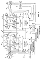
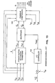
- the preferred embodiment of the present invention is a variable speed wind turbine with a power converter that supplies constant frequency, high quality power at an adjustable power factor to a utility grid.
- the wind turbine 10 includes a variable pitch turbine rotor 12 that is mechanically coupled through a gear box 14 to two 3-phase AC induction generators 16 and 18.
- the gear box 14 includes a fixed-ratio, step-up transmission, so that the generator rotors rotate at a fixed multiple of the speed of the turbine rotor.
- the generators 16 and 18 produce 3-phase AC electricity at a variable frequency that is proportional to the speed of the turbine rotor.
- each generator 16 and 18 is converted from variable frequency AC to fixed frequency AC by power converters that comprise active rectifiers 20 and 22, DC voltage links 24 and 26, inverters 28 and 30, and filters 32 and 34.
- the outputs of the filters 32 and 34 are combined at a transformer 36, the output of which is supplied to the utility grid.
- the two generators both of which rotate at all times whenever the turbine rotor rotates, are preferred over one generator in this embodiment in order to build a high capacity wind turbine while using readily available generators.
- the invention can, of course, be implemented in a wind turbine with only one generator or more than two generators.
- Each of the generators 16 and 18 is controlled separately by generator controllers 38 and 40, which, as explained below, control the torque reacted by the generators by controlling the stator currents or voltages.
- Shaft speed sensors d? and 44 monitor the rotor speed of the two generators, respectively, and supply rotor speed information to the generator controllers 38 and 40 and to a torque command device 46.
- the inverters 28 and 30 are controlled separately by inverter controllers 50 and 52.
- a power factor controller 54 directs the inverter controllers 50 and 52 to provide power factor correction by shifting the output current with respect to the output voltage.
- the torque command device 46 monitors wind turbine performance parameters and generates torque control signals to the generator controllers 38 and 40 and pitch angle control signals to a pitch control unit 48.
- Stored within the torque command device 46 is a table of optimal values of torque, pitch angle, and rotor speed for various operating conditions. These values are given as a function of an estimated wind speed, which is determined by an aerodynamic model of the wind turbine having inputs of rotor speed from the speed sensors 42 and 44, measured pitch angle from the pitch control unit 48, and measured torque from the generator controllers 38 and 40.
- a speed control signal is used to adjust the optimal values of pitch angle and torque found from the table.
- the speed control signal is proportional to the difference between the optimal desired speed from the table and the measured speed from the speed sensors 42 and 44.
- the torque command device 46 thus determines desired values of torque and pitch angle based on the sensed operating conditions and supplies torque and pitch angle control signals to the generator controllers 38, 40 and pitch control unit 48, respectively.
- the power converter for each generator includes an active rectifier, a DC voltage link, an inverter, filters, and associated controls. Both power converters are identical; only one will be explained. More particularly, as illustrated in Figure 2, the active rectifier 20 includes three pairs of active switching devices 60 arranged in a bridge circuit between a +DC rail 68 and a -DC rail 70 of the DC voltage link 24 and each of three stator power taps 72-74 of the generator 16. Each pair of switching devices is coupled between the DC rails 68 and 70, and connected at an intermediate point to one of the stator power taps. Commutation signals that cause the active switching devices to switch on and off originate in a generator control unit 76, which supplies the signals to the switching devices through a drive circuit 78.
- the generator control unit 76 and drive circuit 78 are isolated from the rectifier 20 by optical isolators to minimize interference.
- the commutation signals are complementary for each pair of switching devices, causing one switching device of each pair to switch on and the other switching device of the pair to switch off, as appropriate to achieve the desired stator currents or voltages.
- the switching devices 60 of the rectifier 20 control the stator currents and voltages in the three phase stator windings.
- the switching devices 60 of the rectifier can be any of a number of different types of active switches, including insulated gate bipolar transistors (IGBT), bipolar junction transistors, field effect transistors, Darlington transistors, gate turn-off thyristors, or silicon controlled rectifiers.
- IGBT insulated gate bipolar transistors
- the switching devices 60 of the rectifier are IGBTs, with two IGBTs connected in parallel for each one shown in Figure 2, for a total of twelve devices in the rectifier 20.
- the generator control unit 76 which is part of the generator controller 38, receives sensor inputs of the stator currents i s1 , i s2 , i s3 , and rotor speed ⁇ r , receives a torque reference value T ref from the torque command device 46 ( Figure 1), and generates pulse width modulated (PWM) commutation signals that it supplies to the rectifier switches 60 through the drive circuit 78.
- PWM pulse width modulated
- the DC voltage link 24 consists simply of the two rails 68 and 70, plus an energy storage capacitor 80 connected between the two rails.
- the capacitance of the capacitor 80 is about 15,000 microfarads, and the nominal voltage of the DC link is about 750 volts.
- the inverter 28 also includes three pairs of active switching devices 82 arranged in a bridge circuit between the +DC rail 68 and -DC rail 70 of the DC voltage link 24.
- the intermediate points of the pairs of active switching devices 82 form three output taps 84-86 from which 3-phase electricity flows through the filters 32 and transformer 36 to the utility grid.
- Commutation signals for the active switching devices 82 originate in an inverter control unit 88, which supplies the signals to the switching devices through a drive circuit 90.
- the inverter control unit 88 and drive circuit 90 are isolated from the inverter 28 by optical isolators.
- the commutation signals are complementary for each pair of switching devices, causing one switching device of each pair to switch on and the other switching device of the pair to switch off at any given time.
- the switching devices 82 of the inverter 28 consist of twelve IGBTs arranged in parallel pairs, like the switching devices 60 of the rectifier.
- the inverter control unit 88 which is part of the inverter controller 50, receives sensor inputs of the inverter currents i o1 , i o2 , i o3 , inverter voltages v o1 , v o2 , v o3 , and DC link voltage v dc .
- the inverter currents are sensed at the output taps, while the inverter voltages are sensed at the output of the filters 32 and are isolated through potential transformers 92.
- the inverter control unit 88 also receives, from the power factor controller 54, a power factor signal, a reactive power signal, and an operation mode signal, which define the desired power factor.
- the inverter control unit 88 In response, as will be explained in further detail below, the inverter control unit 88 generates pulse width modulated commutation signals and supplies them to the inverter switches 82 through the drive circuit 90. In addition, the inverter control unit 88 also supplies a feedback signal, Q fb , to the power factor controller 54 that indicates the reactive power being supplied by the inverter 50.
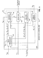
- the control structure of the wind turbine is illustrated in Figure 3 for one of the generators 16.
- the generator control unit 76 includes a field orientation converter 94 that converts the torque reference, T ref , and the rotor speed, ⁇ r , into field oriented control currents, i * / sd and i * / sq, and a rotor flux angle, ⁇ * / s.
- These control variables which are identified as control variables by the * superscript, are used by a PWM controller 95 along with the sensed 3-phase stator currents, i s1 , i s2 , i s3 , to generate the PWM commutation signals, D 1 , D 1 , D 2 , D 2 , D 3 , D 3 .
- the notation D n and D n refers to the base drive signals for the upper (D n ) and lower ( D n ) devices of one pair of rectifier switches 60.
- the PWM controller 95 controls stator electrical quantities, either the stator currents or the stator voltages, depending on the rotor monitor 97 monitors the stator currents, generates a signal indicative of actual torque, T fb , and feeds it back to the torque command device 46.
- Controlling the generator currents and voltages in terms of field coordinates is a key element of the present invention.
- the electric torque of an AC induction machine can be expressed in terms of the stator and rotor currents, but such an expression is difficult to use in a torque control system since the rotor currents of a squirrel-cage induction generator cannot be directly measured.
- Field orientation control eliminates that difficulty.
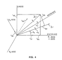
- the rotor flux of an induction machine can be represented by a radial vector ⁇ r with magnitude ⁇ r and angle ⁇ s.
- the field orientation principle defines the stator current in terms of a rotating d,q coordinate system, where a direct (d) axis is aligned with the instantaneous rotor flux vector ⁇ r at angle ⁇ s and a quadrature (q) axis is perpendicular to the rotor flux vector. This is illustrated in Figure 4.
- the stator current vector, i s can be degenerated into a component, i sd , that is parallel to the rotor flux ⁇ r vector and a component, i sq , that is perpendicular to the rotor flux vector.
- the currents i sd and i sq at angle ⁇ s, are the field coordinate representation of the stator current vector.
- Figure 4 also illustrates that ⁇ r is defined as the rotor angular speed and ⁇ s is defined as the angular speed of the rotor flux vector.
- the machine slip speed, ⁇ sl which is the speed of the stator current vector with respect to the rotor, is the difference between ⁇ s , and ⁇ r .
- the d,q coordinate system isolates or decouples a current that creates the rotor flux field, i sd , on the direct axis, from a current that creates torque, i sq , on the quadrature axis. Defining the generator currents in field orientation coordinates permits the generator control unit 76 to convert the torque control commands directly into a desired quadrature axis current, i * / sq, which is then used by the PWM controller 95 to carry out the torque commands of the torque command device 46.
- the stator currents in a balanced, 3-phase coordinate system as represented by the currents on the three stator power taps 72-74 ( Figure 2), can be designated by the variables i s1 , i s2 , and i s3 .
- the balanced, 3-phase stator currents are equivalent to 2-phase stator currents, i s ⁇ and i s ⁇ , defined by the following matrix equation:
- the 2-phase stator currents, i s ⁇ , and i s ⁇ can be converted into the field coordinate currents, i sd and i sq , as a function of the rotor flux angle, ⁇ s , by the following transformation: Transformation from field coordinates to 2-phase coordinates is accomplished by inverting equation (2), which results in the following: Transformation from 2-phase to balanced 3-phase coordinates is found by inverting equation (1): Representations of the stator current vector in the rotating d,q field coordinate system, in the stationary 2-phase ⁇ , ⁇ coordinate system, and in the stationary balanced 3-phase coordinate system are shown in Figure 4.
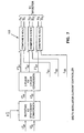
- the structure of the generator control unit 76 is shown in block diagram form in Figure 5.
- the generator control unit is preferably implemented in a digital signal processor ("DSP"), a Texas Instruments model TMS320C25.
- DSP digital signal processor
- TMS320C25 Texas Instruments model
- the generator control unit 76 includes the field orientation converter 94, the torque monitor 97, and the PWM controller 95.
- the PWM controller 95 includes a current controller 96, a voltage controller 98, and a selector circuit 100. These components will be explained in more detail below, but generally, the field orientation converter 94 generates control parameters based on the rotor speed and torque reference signals, the current controller 96 or the voltage controller 98 generates PWM commutation signals for the active switching devices 60, and the selector circuit 100 chooses which of the PWM commutation signals to output to the drive circuit 78.
- the torque monitor 97 senses the actual stator currents, i s1 , i s2 , i s3 , converts them to field coordinate values using equations (1) and (2), and calculates a torque signal, T fb , using equation (8) (see below) for feedback to the torque command device 46.
- the torque monitor 97 thus infers generator torque from the measured currents.
- the computations performed within the DSP of the generator control unit 76 are digital, which requires A/D conversion of the external signals.
- the field orientation converter 94 converts the torque control and rotor flux signals into field coordinates. Using a desired direct axis current, i * / sd, the field orientation converter 94 computes the desired magnitude of the rotor flux, ⁇ * / r.
- the desired flux-producing direct axis current, i * / sd is a function of the particular generator used, and can be predetermined and stored in the DSP. In the preferred embodiment, i * / sd is assumed to be constant. Alternatively, i * / sd can be varied to provide field weakening control, if desired.
- the notation * designates a desired value generated by the control system as opposed to an actual value.
- the desired rotor flux angle, ⁇ * / s, at a particular instant of time can be found.
- ⁇ * / sl desired machine slip speed
- ⁇ * / s desired rotor flux speed
- ⁇ r actual rotor speed
- ⁇ * / s desired instantaneous rotor flux angle.
- Machine slip speed, ⁇ * / sl is found from the calculated values of desired rotor flux, ⁇ * / r, and desired quadrature axis current, i * / sq, using equation (10).
- the measured rotor speed, ⁇ r is then added to the machine slip speed, ⁇ * / sl, to find the desired rotor flux speed, ⁇ * / s, according to equation (11).
- the desired rotor flux speed, ⁇ * / s is then integrated modulo 2 ⁇ to find the desired instantaneous rotor flux angle, ⁇ * / s.
- the computed values for desired field oriented currents, i * / sd and i * / sq, rotor flux, ⁇ * / r, rotor flux speed, ⁇ * / s, and rotor flux angle, ⁇ * / s, are available to the current and voltage controllers 96 and 98 ( Figure 5) for determination of the PWM commutation signals. Transformation of the desired stator currents from field coordinates into stationary 2-phase ⁇ , ⁇ coordinates or balanced 3-phase coordinates, if required by the PWM controller, can be accomplished either in the field orientation converter or in the PWM controller. Here, it is assumed that the transformations occur outside of the field orientation converter 94.
- either the current controller 96 or the voltage controller 98 determines switch states for the active switching devices ( Figure 5).
- the current controller 96 generates PWM commutation signals by choosing a switch state that causes stator currents to approximate the desired currents defined by the field orientation converter.
- the voltage controller 98 generates PWM commutation signals by converting the desired field oriented currents into desired field oriented voltages, transforming them into stator coordinates, and then selecting the appropriate switch state to obtain the desired stator voltages.
- a delta modulator current controller converts the desired field oriented currents into stationary 2-phase stator coordinates, and then to 3-phase stator coordinates to generate desired 3-phase stator currents, i * / s1, i * / s2, i * / s3.
- the desired stator currents are then transformed into 3-phase coordinates using equation (4).
- the delta modulator current controller After converting the desired stator currents from field coordinates into 3-phase coordinates, the delta modulator current controller then periodically compares each desired stator current i * / s1, i * / s2, i * / s3, with the corresponding actual stator current i s1 , i s2 , i s3 , using compare and hold devices 102. If the desired stator current for a phase is greater than the actual stator current, then the upper switching device is switched on and the lower switching device is switched off, otherwise, the upper device is switched on and the lower device is switched off.
- the compare and hold devices 102 set the PWM commutation signals, D 1 , D 1 , D 2 , D 2 , D 3 , D 3 to accomplish the desired switching.
- the switch state so selected remains in effect until the next sample period occurs, at which time the comparisons are performed with updated actual and desired values.
- FIG. 8-10 Another method of current control, one that minimizes a distortion index, is illustrated in Figures 8-10.
- This method generates PWM signals by periodically minimizing a distortion index related directly to total harmonic distortion (THD).
- THD total harmonic distortion
- this method is preferable due to lower THD at comparable frequencies, while requiring fewer switching events and, consequently, less power loss due to switching.
- Minimizing the distortion index, J involves determining which of eight possible switch states of the rectifier switches will produce actual stator currents nearest in value to the desired stator currents.
- One way to accomplish this is shown in Figure 8.
- Switching decisions are made periodically, based on the most recently measured stator currents.
- the distortion index, J can be computed by equations (15) or (16) for each possible switch state.
- the switch state that yields the minimum value of J is output to the selector 100.
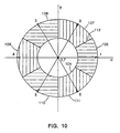
- the desired ⁇ and ⁇ axis voltages, v * / s ⁇ and v * / s ⁇ are compared to the limited number of voltage vectors that could result from the eight possible switch states.
- These voltage vectors, shown in Figure 10 have a magnitude of either zero or the DC link voltage, v dc , and are aligned with the s 1 , s 2 , and s 3 axes.
- the voltage vectors are defined according to the following table: State Switch Setting (v s ⁇ , v s ⁇ ) 0 [ D 1 , D 2 , D 3 ] v dc (0, 0) 1 [D 1 , D 2 , D 3 ] v dc (1, 0) 2 [D 1 , D 2 , D 3 ] v dc (1 /2, 3 /2) 3 [ D 1 , D 2 , D 3 ] v dc (-1/2, 3 /2) 4 [ D 1 , D 2 , D 3 ] v dc (-1,0) 5 [ D 1 , D 2 , D 3 ] v dc (-1/2,- 3 /2) 6 [D 1 , D 2 , D 3 ] v dc (1/2,- 3 /2) 7 [D 1 , D 2 , D 3 ] v dc (0, 0) Since states 0 and 7 define the same zero voltage, there are seven possible stator voltage
- the ⁇ , ⁇ coordinate space can be divided into seven regions: an inner circle 104 of radius v dc /2, plus six 60° sectors 106-111 of outer radius v dc surrounding the inner circle, each sector having a switch state centered at the outer radius thereof.
- Determining the closest voltage vector is a matter of finding into which region the desired voltage vector falls. To do so, the magnitude of the desired voltage vector is first compared to v dc /2 to determine whether the desired voltage vector falls within the inner circle 104. If the magnitude of the desired voltage vector is less than one-half of v dc , then state ⁇ or state 7 is the desired switch state. Choosing between state ⁇ and state 7 is accomplished by selecting the state that requires the fewest number of switches to change state from the previous switch setting.
- operation with the current controller 96 generating the PWM commutation signals occurs at relatively low speeds, where the DC voltage link offers substantial ceiling voltage.
- the current controller 96 keeps the stator currents in close agreement with the desired stator current values. This operation effectively results in current sources for the stator windings, which allows the current controller to ignore the stator voltages.
- the voltage controller 98 takes the stator voltages into consideration.
- the selector 100 senses the rotor speed, ⁇ r , and selects the voltage controller 98 instead of the current controller 96 when the rotor speed exceeds a predetermined value.
- This value can be determined empirically by observing the distortion of the current waveform during operation of the current controller at various speeds.
- the switching point is about 1780 rpm.
- some hysteresis is built into the switching point of the selector 100 so that small oscillations of the rotor speed about the switching point do not cause repeated switching between current control and voltage control.
- the DC link voltage and the generator emf can be monitored to determine at which point to switch between current control and voltage control. Monitoring the DC link voltage is not necessary in the preferred embodiment because the inverter control unit 88 maintains that voltage at a fairly constant value.
- the voltage controller 98 periodically generates a set of PWM commutation signals for switching on and off the active switches of the rectifier.
- the voltage controller monitors the desired and actual torque and flux, as defined by the field oriented currents, i * / sd and i * / sq, compensates for the stator voltages, and generates field oriented control voltages, v * / sd and v * / sq, which are used to generate the commutation signals.
- ⁇ total or global leakage factor
- L s stator inductance
- R s stator resistance.
- the operation of the voltage controller 98 is shown in Figure 11.
- the actual 3-phase stator currents, i s1 , i s2 , i s3 are converted into field oriented coordinates by equations (1) and (2).
- the desired voltage on the quadrature axis, v * / sq is generated by first subtracting the actual quadrature current, i sq , from the desired quadrature current, i * / sq, and then running the resultant through a proportional-integral (PI) controller 114 to generate v ' / sq, which is a measure of quadrature axis current error.
- PI proportional-integral
- the value of v' sq is then compensated by adding a decoupling factor consisting of the two voltage coupling terms on the right side of equation (29), which results in v * / sq as follows:
- v * sq v ' sq + (1- ⁇ ) L s ⁇ * s ⁇ * r R s L o + ⁇ L s ⁇ * s i sd R s
- the desired voltage on the direct axis is generated by first subtracting the rotor flux divided by the mutual inductance, ⁇ * / r/L o , from the desired direct axis current, i * / sd.
- the resultant is then input to another PI controller 116, which generates v' sd as a measurement of direct axis current error.
- PI controller 116 is similar to the PI controller 114 for the quadrature component.
- v * sd v ' sd + (1- ⁇ ) L s ⁇ * r R s L o - ⁇ L s ⁇ * s i sq R s
- the desired field coordinate voltages, v * / sd and v * / sq, have been generated, they are transformed into 3-phase stator voltages by equations (3) and (4), resulting in v * / s1, v * / s2, and v * / s3.
- These reference voltages are modulated by a triangular carrier wave to generate the PWM commutation signals, D 1 , D 1 , D 2 , D 2 , D 3 , and D 3 that are sent to the selector 100 ( Figure 5).
- the triangular carrier wave has a frequency of about 8 kHz, while the comparisons between the reference voltages and the carrier wave are performed continuously or at a rate much higher than 8 kHz.
- Figure 12 illustrates how a computer program is structured for execution in the digital signal processor of the generator control unit.
- the program consists primarily of a main loop and an interrupt service routine.
- the main loop initializes the necessary variables, and then loops until it is interrupted, which occurs periodically, at about 8 kHZ in the preferred embodiment.
- the interrupt service routine performs the calculations necessary for generating the PWM commutation signals, and then updates the control variables.
- the interrupt service routine first reads the stator currents, and then executes the code of either the current controller or the voltage controller to generate and output the appropriate switch states.
- the interrupt routine then reads a value for the torque reference, T ref , and updates the corresponding value of the desired quadrature axis current, i * / sq.
- the routine then reads the speed sensor and computes a new value for the rotor speed, ⁇ r .
- the routine updates the value for desired rotor flux, ⁇ * / r, and the desired instantaneous rotor flux angle, ⁇ * / s.
- the interrupt routine then returns to the main loop, which waits until the next periodic interrupt, at which time the updated values will be used to compute the switch states. All constants used in the calculations are computed in advance, and the expressions are arranged to avoid division, which executes relatively slowly in a DSP.
- the steps performed in the computer program can be executed in different order than is shown in Figure 12, but it is important to calculate and output the switch states as soon as possible after reading the actual stator currents.
- the inverter control unit 88 is preferably implemented with a digital signal processor, a Texas Instruments model TMS320C25. Computer code for implementing the inverter control function in a DSP is disclosed in the microfiche appendix.
- the inverter control unit controls the inverter switch matrix to supply to the utility grid power with adjustable power factor and low THD.
- the inverter and its control unit can supply or absorb reactive power as needed by adjusting the phase difference between the output voltage and current. Low harmonic distortion is achieved in the same way as in the current controller of the generator control unit, by periodically minimizing a distortion index.
- the inverter control unit also controls the voltage of the DC voltage link, to maintain it at a desired value.
- the inverter control unit uses the output voltage as a sinusoidal waveform reference, rotates the reference waveform by a certain phase angle to generate a rotated reference waveform, or "template”, then multiplies the template waveform by a factor, I ref , derived from the DC link voltage, v dc , to generate a desired current waveform.
- I ref a factor derived from the DC link voltage, v dc
- the actual currents are compared to the desired currents to generate the PWM commutation signals for the inverter switches. All of the calculations of the inverter control unit are performed periodically. In the preferred embodiment, the DSP cycles through its calculations every 125 microseconds, equal to a rate of 8 kHz.
- the multiplication factor, I ref is calculated as follows.
- the measured DC link voltage, v dc is subtracted from a desired value of the DC link voltage, v * / dc, to generate an error, which is then input to a PI controller 130.
- the rotational transformation of the reference waveform can be accomplished in either 3-phase or 2-phase coordinates.
- the template values that result from the rotational transformation, v t ⁇ and v t ⁇ are then multiplied by the value of I ref to generate the desired 2-phase output currents, i * / o ⁇ and i * / o ⁇ .
- the desired output currents are input into a current controller 132, which compares them to the actual currents and generates the appropriate PWM commutation signals for the inverter switches.
- the current controller 132 of the inverter control unit can be implemented in the several ways described above for the current controller 96 of the generator control unit, including the delta modulator. Preferably, however, the current controller 132 generates switch states that minimize the distortion index, J, in a manner similar to that described above with respect to Figures 9 and 10.
- the desired output voltages, v * / o ⁇ and v * / o ⁇ , are then compared to the seven available voltage vectors, and the switch state associated with the nearest voltage vector is selected and output to the inverter switches. Determining the nearest voltage vector is accomplished in the same manner as explained above with respect to the generator current controller of Figures 9 & 10.
- a computer program directs the operation of the digital signal processor of the inverter control unit to perform the calculations described above.
- the computer program is structured like that of the generator control unit in that a main loop executes until periodically interrupted, and then an interrupt service routine updates the sensed inputs, PWM switch state, and calculated variables.
- the interrupt service routine running on the inverter control unit DSP first reads the output currents, output voltages and DC link voltage. Then it calculates the optimal switch state, which it outputs to the inverter switches. Then the interrupt routine performs calculations necessary for the next calculation of switch state by rotating the voltage reference to define the template waveform, computing the multiplication factor I ref , and multiplying the template waveform by I ref to compute the desired currents for the next interrupt. Then control passes to the main loop, where it waits until interrupted again. In the preferred embodiment, interruptions occur at a rate of about 8 kHz.
- the power factor controller 54 can control either the power factor angle, ⁇ , or the magnitude of reactive power to supply VARs (Volt-Ampere-Reactive) to the utility.
- the type of power factor control is specified by the operation mode signal that is input into the power factor controller. If the power factor angle is controlled, the power factor controller 54 outputs to the inverter control unit 88 a constant value of ⁇ that is defined by the power factor input signal. If the reactive power is controlled, the power factor controller monitors the reactive power feedback signal, Q fb , compares it to a desired reactive power level defined by the reactive power input signal, and adjusts the power factor angle, o, to obtain the desired reactive power.
- the power factor correction facility of the inverter control unit can be utilized even when the wind turbine is not operating, by operating in a static VAR mode. To do so, the power factor controller 54 sets the power factor angle ⁇ equal to 90°. After the DC link is charged up by the utility through the inverter, the inverter control unit operates as described above to rotate the output current to lead the voltage by 90°. This supplies reactive power to the utility to counteract reactive loads drawing power from the utility grid.
- the invention disclosed herein provides a novel and advantageous variable speed wind turbine.
- the foregoing discussion discloses and describes merely exemplary methods and embodiments of the present invention.
- the invention may be embodied in other specific forms without departing from essential characteristics thereof.
- some aspects of the current controller can be performed in various ways equivalent to those disclosed herein, including using hysteresis control or forced oscillation with triangular intersection.
- the generator need not be a 3-phase squirrel-cage induction generator, but may be any multiphase generator, including a synchronous generator. Certain aspects of the generator control could be performed open-loop, instead of the closed loop control disclosed herein.
- the power converter could have a DC current link, or could be a cyclo-converter instead of a DC voltage link.
- the torque monitor could directly measure torque with a transducer, instead of inferring torque from the measured stator currents. Accordingly, the disclosure of the present invention is intended to be illustrative, but not limiting, of the scope of the invention, which is set forth in the following claims.
Applications Claiming Priority (4)
| Application Number | Priority Date | Filing Date | Title |
|---|---|---|---|
| US649567 | 1991-02-01 | ||
| US07649567 US5083039B1 (en) | 1991-02-01 | 1991-02-01 | Variable speed wind turbine |
| EP98111304A EP0884833B1 (fr) | 1991-02-01 | 1992-01-31 | Eolienne à vitesse variable |
| EP92908256A EP0569556B1 (fr) | 1991-02-01 | 1992-01-31 | Turbine eolienne a vitesse variable |
Related Parent Applications (1)
| Application Number | Title | Priority Date | Filing Date |
|---|---|---|---|
| EP98111304A Division EP0884833B1 (fr) | 1991-02-01 | 1992-01-31 | Eolienne à vitesse variable |
Publications (2)
| Publication Number | Publication Date |
|---|---|
| EP1432115A2 true EP1432115A2 (fr) | 2004-06-23 |
| EP1432115A3 EP1432115A3 (fr) | 2006-04-26 |
Family
ID=24605356
Family Applications (3)
| Application Number | Title | Priority Date | Filing Date |
|---|---|---|---|
| EP98111304A Revoked EP0884833B1 (fr) | 1991-02-01 | 1992-01-31 | Eolienne à vitesse variable |
| EP04006943A Withdrawn EP1432115A3 (fr) | 1991-02-01 | 1992-01-31 | Eolienne à vitesse variable |
| EP92908256A Revoked EP0569556B1 (fr) | 1991-02-01 | 1992-01-31 | Turbine eolienne a vitesse variable |
Family Applications Before (1)
| Application Number | Title | Priority Date | Filing Date |
|---|---|---|---|
| EP98111304A Revoked EP0884833B1 (fr) | 1991-02-01 | 1992-01-31 | Eolienne à vitesse variable |
Family Applications After (1)
| Application Number | Title | Priority Date | Filing Date |
|---|---|---|---|
| EP92908256A Revoked EP0569556B1 (fr) | 1991-02-01 | 1992-01-31 | Turbine eolienne a vitesse variable |
Country Status (9)
| Country | Link |
|---|---|
| US (2) | US5083039B1 (fr) |
| EP (3) | EP0884833B1 (fr) |
| JP (1) | JP3435474B2 (fr) |
| AU (1) | AU1554292A (fr) |
| CA (1) | CA2100672C (fr) |
| DE (3) | DE9219171U1 (fr) |
| DK (2) | DK0884833T3 (fr) |
| ES (2) | ES2219807T3 (fr) |
| WO (1) | WO1992014298A1 (fr) |
Cited By (3)
| Publication number | Priority date | Publication date | Assignee | Title |
|---|---|---|---|---|
| EP1796254A2 (fr) | 2005-11-30 | 2007-06-13 | General Electric Company | Procédé et système de transformation électrique |
| US7279802B2 (en) | 2004-08-11 | 2007-10-09 | Abb Oy | Method in a wind power plant |
| CN101915209A (zh) * | 2010-07-26 | 2010-12-15 | 三一重工股份有限公司 | 风力发电机组及其变桨距控制系统 |
Families Citing this family (467)
| Publication number | Priority date | Publication date | Assignee | Title |
|---|---|---|---|---|
| US5483435A (en) * | 1989-05-15 | 1996-01-09 | Kabushiki Kaisha Toshiba | Power generation system having induction generator and controlled bridge rectifier |
| US5083039B1 (en) * | 1991-02-01 | 1999-11-16 | Zond Energy Systems Inc | Variable speed wind turbine |
| US5155375A (en) * | 1991-09-19 | 1992-10-13 | U.S. Windpower, Inc. | Speed control system for a variable speed wind turbine |
| AU3148893A (en) * | 1991-11-27 | 1993-06-28 | U.S. Windpower, Inc. | Variable speed wind turbine with reduced power fluctuation and a static var mode of operation |
| AU5016493A (en) * | 1992-08-18 | 1994-03-15 | Four Winds Energy Corporation | Wind turbine particularly suited for high-wind conditions |
| US5289042A (en) * | 1992-12-11 | 1994-02-22 | Edward Lis | Wind operated generator |
| JPH06261454A (ja) * | 1993-03-09 | 1994-09-16 | Hitachi Ltd | 発電設備の始動装置 |
| EP0652633B1 (fr) * | 1993-11-09 | 1999-10-13 | Kabushiki Kaisha Toshiba | Système de conversion de puissance et dispositif de commande pour celui-ci |
| US5663631A (en) * | 1994-07-19 | 1997-09-02 | Nippondenso Co., Ltd. | Generator with circuitry for controlling power generation based on rotational speed |
| JPH0835712A (ja) * | 1994-07-26 | 1996-02-06 | Fujitsu General Ltd | 空気調和機の制御装置 |
| US5900722A (en) * | 1994-09-14 | 1999-05-04 | Coleman Powermate, Inc. | Multimode power converter |
| FR2725852B1 (fr) * | 1994-10-14 | 1997-01-03 | Europ Gas Turbines Sa | Generatrice d'energie electrique munie de dispositifs d'adaptation de la frequence |
| DE69530828T2 (de) * | 1994-12-16 | 2004-01-22 | Delphi Technologies, Inc., Troy | Drehmoment- und Ausgang-Steuerung einer Brennkraftslichtmaschine |
| US5663600A (en) * | 1995-03-03 | 1997-09-02 | General Electric Company | Variable speed wind turbine with radially oriented gear drive |
| GB9508051D0 (en) * | 1995-04-20 | 1995-06-07 | Switched Reluctance Drives Ltd | Compensation for input voltage variation in an electric motor drive |
| JP3675014B2 (ja) * | 1995-06-08 | 2005-07-27 | 株式会社デンソー | インバータ制御装置 |
| WO1997004521A1 (fr) * | 1995-07-18 | 1997-02-06 | Midwest Research Institute | Aerogenerateur a vitesse variable dote d'un filtre homopolaire |
| GB2304208B (en) * | 1995-08-07 | 1999-06-23 | Baylis Generators Ltd | Generator |
| US5726560A (en) * | 1995-09-01 | 1998-03-10 | Barber-Colman Company | Switched reluctance generator |
| JPH0984400A (ja) * | 1995-09-14 | 1997-03-28 | Fanuc Ltd | サーボモータの電流制御方法 |
| US5899411A (en) * | 1996-01-22 | 1999-05-04 | Sundstrand Corporation | Aircraft electrical system providing emergency power and electric starting of propulsion engines |
| DE19635960C2 (de) * | 1996-09-05 | 2003-04-10 | Aerodyn Eng Gmbh | Verfahren zum Zuschalten einer Windkraftanlage an das Netz |
| US6177735B1 (en) | 1996-10-30 | 2001-01-23 | Jamie C. Chapman | Integrated rotor-generator |
| DK174291B1 (da) * | 1997-06-26 | 2002-11-18 | Mita Teknik As | Fremgangsmåde til indkobling af en asynkron generator på et vekselspændingsnet, og en elektrisk kobling til brug ved denne fremgangsmåde |
| US6137187A (en) * | 1997-08-08 | 2000-10-24 | Zond Energy Systems, Inc. | Variable speed wind turbine generator |
| US6600240B2 (en) * | 1997-08-08 | 2003-07-29 | General Electric Company | Variable speed wind turbine generator |
| AU774980B2 (en) * | 1997-08-08 | 2004-07-15 | General Electric Company | Variable speed wind turbine generator |
| AU2004220762B2 (en) * | 1997-08-08 | 2007-11-22 | General Electric Company | Variable speed wind turbine generator |
| US6420795B1 (en) * | 1998-08-08 | 2002-07-16 | Zond Energy Systems, Inc. | Variable speed wind turbine generator |
| IES970724A2 (en) * | 1997-10-07 | 1998-02-25 | Gineadoiri Gaoithe Teicneolaio | A wind energy system |
| DE19756777B4 (de) | 1997-12-19 | 2005-07-21 | Wobben, Aloys, Dipl.-Ing. | Verfahren zum Betreiben einer Windenergieanlage sowie Windenergieanlage |
| US6300689B1 (en) * | 1998-05-04 | 2001-10-09 | Ocean Power Technologies, Inc | Electric power generating system |
| NL1009543C2 (nl) * | 1998-07-02 | 2000-01-07 | Lagerwey Windturbine B V | Inrichting voor het omzetten van windenergie in elektrische energie. |
| US6072302A (en) * | 1998-08-26 | 2000-06-06 | Northrop Grumman Corporation | Integrated control system and method for controlling mode, synchronization, power factor, and utility outage ride-through for micropower generation systems |
| US6128204A (en) * | 1998-08-26 | 2000-10-03 | Northrop Grumman Corporation | Line power unit for micropower generation |
| DE19844050A1 (de) * | 1998-09-25 | 2000-03-30 | Abb Daimler Benz Transp | Verfahren zum Steuern und Regeln eines elektrischen Antriebes sowie Vorrichtung zur Durchführung des Verfahrens |
| US6617705B1 (en) * | 1998-10-28 | 2003-09-09 | Ocean Power Technologies, Inc. | Protection arrangement for natural energy power generation systems |
| US6448669B1 (en) | 1998-12-01 | 2002-09-10 | Dillyn M. Elder | Water power generation system |
| US6191496B1 (en) | 1998-12-01 | 2001-02-20 | Dillyn M. Elder | Wind turbine system |
| JP3578930B2 (ja) * | 1999-01-13 | 2004-10-20 | 本田技研工業株式会社 | 発電機および発電機装置 |
| CA2387113C (fr) * | 1999-09-13 | 2003-10-14 | Aloys Wobben | Procede pour reguler la puissance reactive et dispositif pour produire de l'energie electrique dans un reseau electrique |
| DE10020635A1 (de) * | 1999-09-13 | 2001-03-15 | Aloys Wobben | Verfahren zur Blindleistungsregelung sowie Vorrichtung zur Erzeugung elektrischer Energie in einem elektrischen Netz |
| DK199901436A (da) * | 1999-10-07 | 2001-04-08 | Vestas Wind System As | Vindenergianlæg |
| US6362540B1 (en) | 1999-10-20 | 2002-03-26 | Pinnacle West Capital Corporation | Expandable hybrid electric generator and method therefor |
| DE19953238A1 (de) * | 1999-11-04 | 2001-05-17 | Gunther Duensing | Verfahren zur Energieversorgung und Energieversorgungssystem |
| GB9928843D0 (en) * | 1999-12-06 | 2000-02-02 | Lucas Industries Ltd | Switched reluctance generator and a method of controlling such a generator |
| FR2804254B1 (fr) * | 2000-01-26 | 2002-05-31 | Air Liquide | Procede perfectionne de fourniture d'energie electrique au reseau a l'aide d'un generateur de courant alternatif associe a une turbine |
| CN100407547C (zh) * | 2000-01-28 | 2008-07-30 | 康明斯发电机技术有限公司 | 交流发电系统 |
| JP3352662B2 (ja) * | 2000-02-03 | 2002-12-03 | 関西電力株式会社 | 二次電池システムを用いた電力系統安定化装置および電力系統安定化方法 |
| DE20001864U1 (de) * | 2000-02-03 | 2000-04-20 | Siemens Ag | Windradgruppe mit zumindest zwei Windrädern |
| EP1126163A1 (fr) * | 2000-02-16 | 2001-08-22 | Turbowinds N.V./S.A. | Dispositif de réglage du pas de l'hélice pour turbine éolienne |
| DE10011393A1 (de) * | 2000-03-09 | 2001-09-13 | Tacke Windenergie Gmbh | Regelungssystem für eine Windkraftanlage |
| DE10011929B4 (de) * | 2000-03-11 | 2004-07-01 | Wobben, Aloys, Dipl.-Ing. | Synchrongenerator |
| DE10016912C1 (de) * | 2000-04-05 | 2001-12-13 | Aerodyn Eng Gmbh | Turmeigenfrequenzabhängige Betriebsführung von Offshore-Windenergieanlagen |
| SE0001611L (sv) * | 2000-05-03 | 2001-11-04 | Abb Ab | Kraftanläggning samt förfarande för drift därav |
| DE10022974C2 (de) * | 2000-05-11 | 2003-10-23 | Aloys Wobben | Verfahren zum Betreiben einer Windenergieanlage sowie Windenergieanlage |
| EP1284045A1 (fr) * | 2000-05-23 | 2003-02-19 | Vestas Wind System A/S | Eolienne a vitesse variable pourvue d'un convertisseur de matrice |
| ES2165324B2 (es) * | 2000-06-02 | 2004-01-16 | Internat Electronics S A | Sistema de potencia y control para mejorar el rendimiento y calidad de energia producida en aerogeneradores. |
| US6518736B2 (en) * | 2000-06-26 | 2003-02-11 | Toyota Jidosha Kabushiki Kaisha | Mechanical power outputting apparatus and inverter apparatus |
| DE10033183C2 (de) * | 2000-07-07 | 2002-08-08 | Max Planck Gesellschaft | Verfahren und Vorrichtung zur Verarbeitung und Vorhersage von Strömungsparametern turbulenter Medien |
| US6653744B2 (en) * | 2000-08-01 | 2003-11-25 | Clipper Wind Technology, Inc. | Distributed generation drivetrain (DGD) controller for application to wind turbine and ocean current turbine generators |
| US6731019B2 (en) * | 2000-08-07 | 2004-05-04 | Ocean Power Technologies, Inc. | Apparatus and method for optimizing the power transfer produced by a wave energy converter (WEC) |
| DE10040273A1 (de) * | 2000-08-14 | 2002-02-28 | Aloys Wobben | Windenergieanlage |
| US20020024828A1 (en) * | 2000-08-31 | 2002-02-28 | Hidetake Hayashi | Inverter suitable for use with portable AC power supply unit |
| US6239997B1 (en) | 2000-09-01 | 2001-05-29 | Ford Motor Company | System for connecting and synchronizing a supplemental power source to a power grid |
| US20020036430A1 (en) * | 2000-09-28 | 2002-03-28 | Welches Richard S. | Local area grid for distributed power |
| US6608397B2 (en) * | 2000-11-09 | 2003-08-19 | Ntn Corporation | Wind driven electrical power generating apparatus |
| DE10059018C2 (de) * | 2000-11-28 | 2002-10-24 | Aloys Wobben | Windenergieanlage bzw. Windpark bestehend aus einer Vielzahl von Windenergieanlagen |
| DE10063654B4 (de) * | 2000-12-20 | 2008-07-17 | Nucellsys Gmbh | Verfahren und Anordnung zur Erzeugung fahrpedalstellungsabhängiger Stromwerte für die Leistungssteuerung eines oder mehrerer Antriebe in einer mobilen Vorrichtung mit einer Brennstoffzelle für die Energieversorgung |
| US20020084655A1 (en) * | 2000-12-29 | 2002-07-04 | Abb Research Ltd. | System, method and computer program product for enhancing commercial value of electrical power produced from a renewable energy power production facility |
| EP1361639B1 (fr) * | 2001-02-16 | 2008-08-13 | Yanmar Co., Ltd. | Systeme de production d'energie a generateur entraine par moteur |
| FR2821391B1 (fr) * | 2001-02-23 | 2003-06-27 | Jeumont Ind | Procede et dispositif de regulation d'une installation de production d'energie electrique comportant une eolienne |
| JP3873634B2 (ja) * | 2001-02-28 | 2007-01-24 | 株式会社日立製作所 | 風力発電システム |
| DE10109553B4 (de) * | 2001-02-28 | 2006-03-30 | Wobben, Aloys, Dipl.-Ing. | Luftdichteabhängige Leistungsregelung |
| DE10117212A1 (de) * | 2001-04-06 | 2002-10-10 | Dewind Ag | Verfahren zum Betrieb einer Windenergieanlage |
| DK2811158T3 (en) * | 2001-04-20 | 2018-05-22 | Wobben Properties Gmbh | Process for operating a wind power plant |
| DE10119624A1 (de) * | 2001-04-20 | 2002-11-21 | Aloys Wobben | Verfahren zum Betreiben einer Windenergieanlage |
| DE10136974A1 (de) * | 2001-04-24 | 2002-11-21 | Aloys Wobben | Verfahren zum Betreiben einer Windenergieanlage |
| US6670721B2 (en) * | 2001-07-10 | 2003-12-30 | Abb Ab | System, method, rotating machine and computer program product for enhancing electric power produced by renewable facilities |
| DE10134883A1 (de) * | 2001-07-18 | 2003-01-30 | Abb Research Ltd | Verfahren und Vorrichtung zur drehzahlstellbaren leistungselektronischen Regelung einer getriebelosen Windkraftanlage |
| US6492801B1 (en) | 2001-08-21 | 2002-12-10 | Southern Company Services, Inc. | Method, apparatus, and system for real time reactive power output monitoring and predicting |
| US6661113B1 (en) | 2001-08-31 | 2003-12-09 | Walter E. Bonin | Power generator |
| EP2113980B1 (fr) * | 2001-09-28 | 2016-02-24 | Wobben Properties GmbH | Procédé de fonctionnement d'une éolienne |
| US6703718B2 (en) * | 2001-10-12 | 2004-03-09 | David Gregory Calley | Wind turbine controller |
| US6836028B2 (en) * | 2001-10-29 | 2004-12-28 | Frontier Engineer Products | Segmented arc generator |
| DE10153644C2 (de) * | 2001-10-31 | 2003-11-20 | Aloys Wobben | Windenergieanlage mit berührungsloser Energieübertragung auf den Rotor |
| GB0128590D0 (en) * | 2001-11-29 | 2002-01-23 | Engineering Business Ltd | Electricity generators |
| GB0128662D0 (en) * | 2001-11-30 | 2002-01-23 | Rolls Royce Plc | Improvements in or relating to generator arrangements |
| US7773614B1 (en) * | 2001-12-05 | 2010-08-10 | Adaptix, Inc. | Wireless communication subsystem with a digital interface |
| US20040080165A1 (en) * | 2001-12-31 | 2004-04-29 | Capstone Turbine Corporation | Turbogenerator/motor controller with ancillary energy storage/discharge |
| JP4023171B2 (ja) * | 2002-02-05 | 2007-12-19 | トヨタ自動車株式会社 | 負荷駆動装置、負荷駆動装置における電力貯蔵装置の充電制御方法および充電制御をコンピュータに実行させるためのプログラムを記録したコンピュータ読取可能な記録媒体 |
| US7015595B2 (en) * | 2002-02-11 | 2006-03-21 | Vestas Wind Systems A/S | Variable speed wind turbine having a passive grid side rectifier with scalar power control and dependent pitch control |
| JP3970083B2 (ja) * | 2002-04-23 | 2007-09-05 | 住友電気工業株式会社 | レドックスフロー電池システムの運転方法 |
| DK1536507T3 (da) * | 2002-04-23 | 2012-07-23 | Sumitomo Electric Industries | Fremgangsmåde til at designe et redox-flow-batterisystem |
| US6919650B2 (en) * | 2002-05-31 | 2005-07-19 | Ballard Power Systems Corporation | Hybrid synchronization phase angle generation method |
| US7071579B2 (en) * | 2002-06-07 | 2006-07-04 | Global Energyconcepts,Llc | Wind farm electrical system |
| DE10232423A1 (de) * | 2002-07-17 | 2004-01-29 | Ge Wind Energy Gmbh | Verfahren zum Betreiben einer Windenergieanlage und Windenergieanlage zum Ausführen derartiger Verfahren |
| JP4135420B2 (ja) * | 2002-07-19 | 2008-08-20 | 株式会社明電舎 | 風力発電機の出力電力平滑化制御装置 |
| CA2493709A1 (fr) * | 2002-07-24 | 2004-01-29 | Sunpower Co., Ltd. | Eolienne, et procede de realisation |
| JP2005538673A (ja) * | 2002-09-10 | 2005-12-15 | デヴィント ゲエムベーハー | 超同期カスケード接続を備えた風力発電施設の運転方法 |
| US6787259B2 (en) * | 2002-09-12 | 2004-09-07 | Metallic Power, Inc. | Secondary power source for use in a back-up power system |
| AU2002368205A1 (en) * | 2002-09-13 | 2004-04-30 | Abb Ab | Wind power fed network |
| US6879053B1 (en) * | 2002-10-22 | 2005-04-12 | Youtility, Inc. | Transformerless, load adaptive speed controller |
| WO2004038892A2 (fr) * | 2002-10-22 | 2004-05-06 | Youtility, Inc. | Generateur a vitesse variable hybride/convertisseur de courant d'alimentation a alimentation sans interruption |
| ES2392683T3 (es) * | 2002-11-01 | 2012-12-12 | Vestas Wind Systems A/S | Disposición de circuito para su uso en un sistema de turbina eólica de velocidad variable que comprende un generador de inducción de doble alimentación y un convertidor reversible |
| JP4168252B2 (ja) * | 2002-12-27 | 2008-10-22 | 株式会社安川電機 | 発電システムおよびその制御方法 |
| DE10300174B3 (de) * | 2003-01-08 | 2004-12-23 | Nordex Energy Gmbh | Windenergieanlage mit mindestens zwei Komponenten und einem Datennetz |
| US6984897B2 (en) * | 2003-01-23 | 2006-01-10 | Spellman High Voltage Electronics Corporation | Electro-mechanical energy conversion system having a permanent magnet machine with stator, resonant transfer link and energy converter controls |
| US6921985B2 (en) * | 2003-01-24 | 2005-07-26 | General Electric Company | Low voltage ride through for wind turbine generators |
| SE524670C2 (sv) * | 2003-01-30 | 2004-09-14 | Abb Ab | En anordning och ett förfarande för effektbalansering |
| US6888262B2 (en) * | 2003-02-03 | 2005-05-03 | General Electric Company | Method and apparatus for wind turbine rotor load control |
| US7004724B2 (en) * | 2003-02-03 | 2006-02-28 | General Electric Company | Method and apparatus for wind turbine rotor load control based on shaft radial displacement |
| US7160083B2 (en) * | 2003-02-03 | 2007-01-09 | General Electric Company | Method and apparatus for wind turbine rotor load control |
| US7322794B2 (en) * | 2003-02-03 | 2008-01-29 | General Electric Company | Method and apparatus for condition-based monitoring of wind turbine components |
| WO2004083630A2 (fr) * | 2003-03-21 | 2004-09-30 | Vestas Wind Systems A/S | Procedes permettant de deplacer les elements de rotation d'une eolienne durant le transport ou l'immobilisation, procede permettant de commander le deplacement des elements de rotation, nacelle, dispositif auxiliaire, systeme de commande et de surveillance et utilisation de celui-ci |
| WO2004088815A1 (fr) * | 2003-03-31 | 2004-10-14 | Mayekawa Mfg. Co., Ltd. | Systeme d'exploitation de l'energie du charbon par transmission d'alimentation supraconductrice |
| EP1467094B2 (fr) * | 2003-04-08 | 2017-03-01 | GE Energy Power Conversion GmbH | Eolienne et son procédé de fonctionnement |
| US6940185B2 (en) * | 2003-04-10 | 2005-09-06 | Advantek Llc | Advanced aerodynamic control system for a high output wind turbine |
| US7042110B2 (en) * | 2003-05-07 | 2006-05-09 | Clipper Windpower Technology, Inc. | Variable speed distributed drive train wind turbine system |
| FI115874B (fi) * | 2003-05-27 | 2005-07-29 | Abb Oy | Menetelmä kaksoissyöttöisen koneen säätämiseksi |
| DE10327344A1 (de) * | 2003-06-16 | 2005-01-27 | Repower Systems Ag | Windenergieanlage |
| DE10330473A1 (de) * | 2003-07-05 | 2005-01-27 | Alstom Technology Ltd | Frequenzumwandler für Hochgeschwindigkeitsgeneratoren |
| DE10336068B4 (de) * | 2003-08-06 | 2006-04-06 | Siemens Ag | Verfahren zur gesteuerten Einprägung eines Ständerstrom- und eines Drehmoment-Sollwertes für eine stromrichtergespeiste Drehfeldmaschine |
| DE10338127C5 (de) * | 2003-08-15 | 2015-08-06 | Senvion Se | Windenergieanlage mit einem Rotor |
| US6924565B2 (en) * | 2003-08-18 | 2005-08-02 | General Electric Company | Continuous reactive power support for wind turbine generators |
| US8560476B2 (en) * | 2003-08-26 | 2013-10-15 | The Trustees Of Columbia University In The City Of New York | Martingale control of production for optimal profitability of oil and gas fields |
| US7119452B2 (en) * | 2003-09-03 | 2006-10-10 | General Electric Company | Voltage control for wind generators |
| WO2005025026A1 (fr) | 2003-09-03 | 2005-03-17 | Repower Systems Ag | Procede pour faire fonctionner ou reguler une eolienne et procede pour mettre a disposition une puissance de regulation primaire au moyen d'eoliennes |
| DE10341504A1 (de) * | 2003-09-03 | 2005-06-09 | Repower Systems Ag | Verfahren zum Betrieb einer Windenergieanlage, Windenergieanlage und Verfahren zur Bereitstellung von Regelleistung mit Windenergieanlagen |
| US6981839B2 (en) * | 2004-03-09 | 2006-01-03 | Leon Fan | Wind powered turbine in a tunnel |
| CN100379113C (zh) * | 2003-09-11 | 2008-04-02 | 上海交通大学 | 同时实现并网发电和电网无功功率补偿的一体化方法 |
| DE10344392A1 (de) * | 2003-09-25 | 2005-06-02 | Repower Systems Ag | Windenergieanlage mit einem Blindleistungsmodul zur Netzstützung und Verfahren dazu |
| JP4269941B2 (ja) * | 2004-01-08 | 2009-05-27 | 株式会社日立製作所 | 風力発電装置およびその制御方法 |
| JP4155196B2 (ja) * | 2004-01-13 | 2008-09-24 | 株式会社日立製作所 | 回転電機制御装置および発電システム |
| US7265456B2 (en) * | 2004-01-15 | 2007-09-04 | Vrb Bower Systems Inc. | Power generation system incorporating a vanadium redox battery and a direct current wind turbine generator |
| US8277964B2 (en) | 2004-01-15 | 2012-10-02 | Jd Holding Inc. | System and method for optimizing efficiency and power output from a vanadium redox battery energy storage system |
| AU2004316333B2 (en) * | 2004-02-27 | 2010-09-02 | Mitsubishi Heavy Industries, Ltd. | Wind turbine generator, active damping method thereof, and windmill tower |
| CN1926742B (zh) | 2004-03-12 | 2011-05-25 | 通用电气公司 | 用于操作发电机变频器的方法以及具有根据这种方法操作的发电机的风能涡轮机 |
| DE102004013131A1 (de) * | 2004-03-17 | 2005-10-06 | Siemens Ag | Windkraftanlage |
| ITMI20040778A1 (it) * | 2004-04-21 | 2004-07-21 | Trimmer S A | Generatore eolico a doppia utenza |
| US7038330B2 (en) * | 2004-04-23 | 2006-05-02 | Rwe Piller Gmbh | Protection for wind power station |
| US7148652B2 (en) * | 2004-04-30 | 2006-12-12 | Ace-Tronics Company, Inc. | Method and apparatus for determining and handling brake failures in open loop variable frequency drive motors |
| US7248946B2 (en) * | 2004-05-11 | 2007-07-24 | Advanced Energy Conversion, Llc | Inverter control methodology for distributed generation sources connected to a utility grid |
| DE102004024563B4 (de) * | 2004-05-18 | 2008-01-10 | Nordex Energy Gmbh | Verfahren zur Erzeugung von Notstrom für eine Windenergieanlage mit einem Hilfsgenerator |
| CA2573079A1 (fr) * | 2004-06-23 | 2006-01-05 | Trailblazer Production Company, Llc | Procede et systeme de generation d'energie |
| US7095129B2 (en) * | 2004-06-30 | 2006-08-22 | General Electric Company | Methods and apparatus for rotor load control in wind turbines |
| US7175389B2 (en) * | 2004-06-30 | 2007-02-13 | General Electric Company | Methods and apparatus for reducing peak wind turbine loads |
| JP3918837B2 (ja) | 2004-08-06 | 2007-05-23 | 株式会社日立製作所 | 風力発電装置 |
| US7081696B2 (en) * | 2004-08-12 | 2006-07-25 | Exro Technologies Inc. | Polyphasic multi-coil generator |
| FI119579B (fi) * | 2004-08-13 | 2008-12-31 | Abb Oy | Menetelmä jännitevälipiirillisessä taajuusmuuttajassa ja taajuusmuuttaja |
| KR101070906B1 (ko) * | 2004-10-01 | 2011-10-06 | 설승기 | 분산 발전 시스템 및 그 제어 방법 |
| US7980825B2 (en) * | 2005-10-18 | 2011-07-19 | Robert A. Vanderhye | Savonius rotor blade construction particularly for a three bladed savonius rotor |
| JP4449775B2 (ja) * | 2005-02-17 | 2010-04-14 | 株式会社日立製作所 | 二次励磁用電力変換装置 |
| US7215035B2 (en) * | 2005-02-22 | 2007-05-08 | Xantrex Technology, Inc. | Method and apparatus for converting wind generated electricity to constant frequency electricity for a utility grid |
| US7126236B2 (en) * | 2005-03-15 | 2006-10-24 | General Electric Company | Methods and apparatus for pitch control power conversion |
| KR100704482B1 (ko) * | 2005-04-01 | 2007-04-09 | 엘지전자 주식회사 | 저속 영역과 고속 영역에서의 발전 효율이 개선된 에스알발전기 |
| US7314346B2 (en) * | 2005-11-03 | 2008-01-01 | Vanderhye Robert A | Three bladed Savonius rotor |
| CA2608034C (fr) * | 2005-05-13 | 2015-03-31 | Siemens Aktiengesellschaft | Parc eolien et procede de controle |
| GB0510066D0 (en) | 2005-05-17 | 2005-06-22 | Goodrich Control Sys Ltd | A controller for a permanent magnet generator and a generator in combination with such a controller |
| US8649911B2 (en) * | 2005-06-03 | 2014-02-11 | General Electric Company | System and method for operating a wind farm under high wind speed conditions |
| MX2007016176A (es) * | 2005-07-01 | 2008-04-15 | Vestas Wind Sys As | Turbina eolica de velocidad de rotor variable, plataforma eolica, metodo para transmitir energia electrica y metodo para dar servicio o inspeccionar una turbina eolica de velocidad de rotor variable. |
| US7573160B2 (en) * | 2005-07-20 | 2009-08-11 | General Electric Company | Methods and apparatus for controlling windfarms and windfarms controlled thereby |
| US7476985B2 (en) * | 2005-07-22 | 2009-01-13 | Gamesa Innovation & Technology, S.L. | Method of operating a wind turbine |
| JP4561518B2 (ja) * | 2005-07-27 | 2010-10-13 | 株式会社日立製作所 | 交流励磁同期発電機を用いた発電装置とその制御方法。 |
| US7239036B2 (en) * | 2005-07-29 | 2007-07-03 | General Electric Company | System and method for power control in wind turbines |
| DK1752660T3 (da) * | 2005-08-12 | 2013-06-17 | Gen Electric | Beskyttelsesindretning mod overspænding til en vindmølle |
| US8462889B2 (en) | 2005-10-04 | 2013-06-11 | Hypres, Inc. | Oversampling digital receiver for radio-frequency signals |
| US7923965B2 (en) * | 2005-10-10 | 2011-04-12 | General Electric Company | Methods for coupling an energy storage system to a variable energy supply system |
| US7233079B1 (en) * | 2005-10-18 | 2007-06-19 | Willard Cooper | Renewable energy electric power generating system |
| JP4575272B2 (ja) * | 2005-10-27 | 2010-11-04 | 株式会社日立製作所 | 分散型電源システム及び系統安定化方法 |
| US20070100506A1 (en) * | 2005-10-31 | 2007-05-03 | Ralph Teichmann | System and method for controlling power flow of electric power generation system |
| US7511385B2 (en) * | 2005-11-11 | 2009-03-31 | Converteam Ltd | Power converters |
| GB0523087D0 (en) * | 2005-11-11 | 2005-12-21 | Alstom Power Conversion Ltd | Power converters |
| US7345373B2 (en) * | 2005-11-29 | 2008-03-18 | General Electric Company | System and method for utility and wind turbine control |
| US7319307B2 (en) * | 2005-12-16 | 2008-01-15 | General Electric Company | Power balancing of multiple synchronized generators |
| CN101600882A (zh) * | 2006-01-20 | 2009-12-09 | 西南风力公司 | 风力涡轮机的失速控制器以及触发条件的控制装置 |
| US7423412B2 (en) * | 2006-01-31 | 2008-09-09 | General Electric Company | Method, apparatus and computer program product for injecting current |
| WO2007092621A2 (fr) * | 2006-02-09 | 2007-08-16 | Windera Power Systems, Inc. | Turbine présentant une sortie de tension et de fréquence constantes |
| US7352075B2 (en) * | 2006-03-06 | 2008-04-01 | General Electric Company | Methods and apparatus for controlling rotational speed of a rotor |
| EP1956375B1 (fr) | 2006-03-15 | 2011-01-12 | Siemens Aktiengesellschaft | Éolienne et procédé pour déterminer au moins un paramètre de rotation d'un rotor d'éolienne |
| US7816801B2 (en) | 2006-03-16 | 2010-10-19 | International Components Corporation, Inc. | Speed sensing circuit for a wind turbine generator |
| US7508089B2 (en) * | 2006-03-16 | 2009-03-24 | International Components Corporation | Over speed control circuit for a wind turbine generator which maximizes the power exported from the generator over time |
| US7425771B2 (en) * | 2006-03-17 | 2008-09-16 | Ingeteam S.A. | Variable speed wind turbine having an exciter machine and a power converter not connected to the grid |
| CN101401294B (zh) * | 2006-03-17 | 2013-04-17 | 英捷电力技术有限公司 | 具有激励器设备和不连接至电网的功率变换器的变速风机 |
| US7355294B2 (en) * | 2006-05-22 | 2008-04-08 | General Electric Company | Method and system for wind turbine blade movement |
| US7218012B1 (en) * | 2006-05-31 | 2007-05-15 | General Electric Company | Emergency pitch drive power supply |
| WO2007140466A2 (fr) * | 2006-05-31 | 2007-12-06 | Wisconsin Alumni Research Foundation | Architecture de conditionnement de l'énergie pour une éolienne |
| US7586216B2 (en) * | 2006-06-02 | 2009-09-08 | General Electric Company | Redundant electrical brake and protection system for electric generators |
| JP2009540776A (ja) | 2006-06-08 | 2009-11-19 | エクスロ テクノロジーズ インコーポレイテッド | 多相複数コイル発電機 |
| US7312537B1 (en) * | 2006-06-19 | 2007-12-25 | General Electric Company | Methods and apparatus for supplying and/or absorbing reactive power |
| JP2008011607A (ja) * | 2006-06-28 | 2008-01-17 | Hitachi Ltd | 可変速風力発電システム |
| EP2044326B1 (fr) * | 2006-07-06 | 2018-08-22 | Acciona Windpower, S.A. | Systèmes, procédés et appareils pour un contrôleur de turbine éolienne |
| DE102006040970B4 (de) * | 2006-08-19 | 2009-01-22 | Nordex Energy Gmbh | Verfahren zum Betrieb einer Windenergieanlage |
| US7417332B2 (en) * | 2006-08-24 | 2008-08-26 | General Electric Company | Method and apparatus of monitoring a machine |
| US7617741B1 (en) * | 2006-09-19 | 2009-11-17 | Robert Vanderhye | Wind turbine testing |
| EP1914872A1 (fr) | 2006-10-17 | 2008-04-23 | Siemens Aktiengesellschaft | Parc éolien |
| DK1914419T3 (en) * | 2006-10-19 | 2015-12-21 | Siemens Ag | Wind energy installation and method for controlling the output power from a wind power installation |
| US7629705B2 (en) | 2006-10-20 | 2009-12-08 | General Electric Company | Method and apparatus for operating electrical machines |
| US20080112807A1 (en) * | 2006-10-23 | 2008-05-15 | Ulrich Uphues | Methods and apparatus for operating a wind turbine |
| US7710081B2 (en) | 2006-10-27 | 2010-05-04 | Direct Drive Systems, Inc. | Electromechanical energy conversion systems |
| DE102006051546A1 (de) * | 2006-11-02 | 2008-05-08 | Nordex Energy Gmbh | Verfahren zum Betrieb einer Windenergieanlage mit einem doppelt gespeisten Asynchrongenerator sowie Windenergieanlage mit einem doppelt gespeisten Asynchrongenerator |
| US7642666B2 (en) * | 2006-11-02 | 2010-01-05 | Hitachi, Ltd. | Wind power generation apparatus, wind power generation system and power system control apparatus |
| US7417333B2 (en) * | 2006-11-02 | 2008-08-26 | General Electric Company | Methods and apparatus for controlling current in an electrical machine |
| FI119086B (fi) * | 2006-11-06 | 2008-07-15 | Abb Oy | Menetelmä ja järjestely tuulivoimalan yhteydessä |
| WO2008055503A2 (fr) * | 2006-11-08 | 2008-05-15 | Vestas Wind Systems A/S | Procédé de commande d'un groupe d'éoliennes reliées à un réseau électrique, procédé de planification de la stratégie d'un réseau électrique comprenant un groupe d'éoliennes reliées au réseau électrique et groupes d'& |
| US7569943B2 (en) * | 2006-11-21 | 2009-08-04 | Parker-Hannifin Corporation | Variable speed wind turbine drive and control system |
| GB0625121D0 (en) * | 2006-12-18 | 2007-01-24 | Gendrive Ltd | Electrical energy converter |
| DE102006060323A1 (de) * | 2006-12-20 | 2008-06-26 | Nordex Energy Gmbh | Verfahren zum Betreiben einer Windenergieanlage bei plötzlichen Spannungsänderungen im Netz |
| WO2008077974A1 (fr) * | 2006-12-22 | 2008-07-03 | Wind To Power System, S.L. | Générateur asynchrone à double alimentation |
| EP2128440A4 (fr) * | 2006-12-28 | 2012-03-14 | Wind To Power System S L | Générateur asynchrone avec régulation de la tension appliquée sur le stator |
| US7622815B2 (en) * | 2006-12-29 | 2009-11-24 | Ingeteam Energy, S.A. | Low voltage ride through system for a variable speed wind turbine having an exciter machine and a power converter not connected to the grid |
| GB2446432A (en) * | 2007-02-07 | 2008-08-13 | Semplice Energy Ltd | A generator connection arrangement |
| FI119898B (fi) * | 2007-02-14 | 2009-04-30 | Konecranes Oyj | Generaattorikokoonpano |
| US8368236B2 (en) | 2007-03-27 | 2013-02-05 | Rahamim Ben-David | System and method for generating an alternating current output signal |
| CA2682487A1 (fr) | 2007-03-27 | 2008-10-02 | C.A.P.S. Energy Ltd. | Systeme et procede de generation d'un signal de sortie de courant alternatif |
| DE102007018888A1 (de) | 2007-04-19 | 2008-10-30 | Repower Systems Ag | Windenergieanlage mit Blindleistungsvorgabe |
| WO2008131777A2 (fr) * | 2007-04-30 | 2008-11-06 | Vestas Wind Systems A/S | Turbine éolienne à vitesse variable ayant un générateur d'induction à double alimentation compensé pour faire varier la vitesse du rotor |
| US20090211260A1 (en) * | 2007-05-03 | 2009-08-27 | Brayton Energy, Llc | Multi-Spool Intercooled Recuperated Gas Turbine |
| US8513911B2 (en) * | 2007-05-11 | 2013-08-20 | Converteam Technology Ltd. | Power converters |
| GB2449119B (en) | 2007-05-11 | 2012-02-29 | Converteam Technology Ltd | Power converters |
| GB2449427B (en) * | 2007-05-19 | 2012-09-26 | Converteam Technology Ltd | Control methods for the synchronisation and phase shift of the pulse width modulation (PWM) strategy of power converters |
| WO2008145778A1 (fr) | 2007-06-01 | 2008-12-04 | Acciona Windpower, S.A. | Système et procédé de commande d'une éolienne |
| DE102007026995C5 (de) * | 2007-06-07 | 2017-03-30 | Senvion Gmbh | Drehzahlbestimmung |
| US7525211B2 (en) * | 2007-06-19 | 2009-04-28 | Marvin Russell H | Control system for twin turbine wind power generating system |
| EP2017953A2 (fr) | 2007-07-16 | 2009-01-21 | Gamesa Innovation & Technology, S.L. | Système de commande à vitesse variable |
| GB0714777D0 (en) * | 2007-07-30 | 2007-09-12 | Orbital 2 Ltd | Improvements in and relating to electrical power generation from fluid flow |
| US7847526B2 (en) * | 2007-09-28 | 2010-12-07 | General Electric Company | System and method for controlling torque ripples in synchronous machines |
| US7683568B2 (en) * | 2007-09-28 | 2010-03-23 | Rockwell Automation Technologies, Inc. | Motor drive using flux adjustment to control power factor |
| US7382244B1 (en) | 2007-10-04 | 2008-06-03 | Kd Secure | Video surveillance, storage, and alerting system having network management, hierarchical data storage, video tip processing, and vehicle plate analysis |
| US8013738B2 (en) | 2007-10-04 | 2011-09-06 | Kd Secure, Llc | Hierarchical storage manager (HSM) for intelligent storage of large volumes of data |
| US8183707B2 (en) * | 2007-10-30 | 2012-05-22 | General Electric Company | Method of controlling a wind energy system and wind speed sensor free wind energy system |
| US7884492B2 (en) * | 2007-11-13 | 2011-02-08 | General Electric Company | Methods and systems for wind turbine generators |
| US8987939B2 (en) | 2007-11-30 | 2015-03-24 | Caterpillar Inc. | Hybrid power system with variable speed genset |
| WO2009068036A2 (fr) * | 2007-11-30 | 2009-06-04 | Vestas Wind Systems A/S | Éolienne, procédé pour commander une éolienne et utilisation de celle-ci |
| EP2232063B1 (fr) * | 2007-11-30 | 2017-09-27 | Vestas Wind Systems A/S | Éolienne, procédé pour commander une éolienne et utilisation de celle-ci |
| WO2009073582A2 (fr) * | 2007-11-30 | 2009-06-11 | Fishman Oleg S | Systèmes d'inverseurs de source de courant régulés synchronisés à grille multiphase |
| CN101809856B (zh) * | 2007-12-14 | 2014-02-26 | 三菱重工业株式会社 | 风力发电系统及其运转控制方法 |
| WO2009081205A2 (fr) * | 2007-12-20 | 2009-07-02 | Enecsys Limited | Synchronisation de réseau de distribution |
| ES2430046T3 (es) * | 2007-12-28 | 2013-11-18 | Vestas Wind Systems A/S | Aparato y procedimiento para hacer funcionar una turbina eólica en condiciones de voltaje de red de suministro bajo |
| WO2009083445A1 (fr) † | 2007-12-28 | 2009-07-09 | Vestas Wind Systems A/S | Appareil et procédé pour régler la puissance réactive d'un groupe de turbines éoliennes connectées à un réseau électrique |
| US8805595B2 (en) * | 2008-01-17 | 2014-08-12 | General Electric Company | Wind turbine arranged for independent operation of its components and related method and computer program |
| DE102008007448A1 (de) * | 2008-02-01 | 2009-08-13 | Woodward Seg Gmbh & Co. Kg | Verfahren zum Betreiben einer Windenergieanlage |
| WO2009102842A2 (fr) * | 2008-02-12 | 2009-08-20 | Enphase Energy, Inc. | Procédé et appareil pour compensation de var distribué |
| DE102008011139A1 (de) * | 2008-02-26 | 2009-08-27 | Nordex Energy Gmbh | Regler für einen Blatteinstellwinkel mindestens eines Rotorblatts einer Windenergieanlage |
| EP2096732B1 (fr) * | 2008-02-27 | 2010-09-01 | ABB Schweiz AG | Système d'énergie comprenant une éolienne ou une turbine hydraulique |
| CA2753879A1 (fr) * | 2008-02-29 | 2009-09-03 | Efficient Drivetrains, Inc. | Systemes d'eolienne ameliores utilisant des transmissions et des commandes variables de facon ininterrompue |
| US7952232B2 (en) * | 2008-03-13 | 2011-05-31 | General Electric Company | Wind turbine energy storage and frequency control |
| US8004100B2 (en) * | 2008-03-14 | 2011-08-23 | General Electric Company | Model based wind turbine drive train vibration damper |
| ES2327486B1 (es) * | 2008-03-14 | 2010-07-14 | Ingeteam Energy, S.A. | Metodo de operacion de una turbina eolica para garantizar regulacion primaria o secundaria en una red electrica. |
| WO2009117742A1 (fr) * | 2008-03-21 | 2009-09-24 | The Trustees Of Columbia University In The City Of New York | Procédés et systèmes de détermination de l’efficacité de projets d’amélioration du capital |
| WO2009117741A1 (fr) * | 2008-03-21 | 2009-09-24 | The Trustees Of Columbia University In The City Of New York | Centres de contrôle d'aide à la décision |
| DE102008017715A1 (de) * | 2008-04-02 | 2009-10-15 | Nordex Energy Gmbh | Verfahren zum Betreiben einer Windenergieanlage mit einer doppelt gespeisten Asynchronmaschine sowie Windenergieanlage mit einer doppelt gespeisten Asynchronmaschine |
| US7944184B2 (en) * | 2008-04-07 | 2011-05-17 | Korea Electric Power Corporation | Static compensator apparatus for HVDC system |
| JP4759587B2 (ja) | 2008-04-15 | 2011-08-31 | 株式会社日立エンジニアリング・アンド・サービス | 風力発電所 |
| US8311679B2 (en) * | 2008-04-21 | 2012-11-13 | Paluszek Michael A | Matrix converters for wind energy conversion systems |
| US20090273192A1 (en) * | 2008-04-30 | 2009-11-05 | Guven Mustafa K | Doubly fed axial flux induction generator |
| US20090295231A1 (en) * | 2008-05-30 | 2009-12-03 | Gaffney Shawn J | Intelligent Power Collection Network |
| ES2333393B1 (es) * | 2008-06-06 | 2011-01-07 | Accioona Windpower, S.A | Sistema y metodo de control de un aerogenerador. |
| ES2345645B1 (es) | 2008-06-09 | 2011-07-13 | GAMESA INNOVATION & TECHNOLOGY, S.L. | Instalacion de energia eolica y procedimiento de modificacion del paso de pala en una instalacion de energia eolica. |
| WO2009155467A2 (fr) * | 2008-06-18 | 2009-12-23 | Duffey Christopher K | Générateur synchrone à vitesse variable |
| BRPI0915433A2 (pt) * | 2008-06-19 | 2019-09-24 | Tennant Co | método, e, dispositivo. |
| DE102008028809B3 (de) * | 2008-06-19 | 2010-04-01 | Repower Systems Ag | Ansteuerschaltung und -verfahren für Wechselrichter von Windenergieanlagen |
| WO2009153614A2 (fr) * | 2008-06-20 | 2009-12-23 | Clipper Windpower Technology, Inc. | Moyens et procédé de commande d'éolienne pour acquisition de puissance maximale |
| US8624422B2 (en) * | 2008-07-22 | 2014-01-07 | Vestas Wind Systems A/S | Method of controlling a variable speed wind turbine |
| US8179009B2 (en) | 2008-07-28 | 2012-05-15 | Direct Drive Systems, Inc. | Rotor for an electric machine |
| US8030791B2 (en) * | 2008-07-31 | 2011-10-04 | Rockwell Automation Technologies, Inc. | Current source converter-based wind energy system |
| BRPI0822978A2 (pt) * | 2008-08-01 | 2015-06-23 | Petra Solar Inc | Sistema e método de geração de energia solar distribuída, e, controlador de fluxo de energia solar distribuída. |
| US8368238B2 (en) * | 2008-08-14 | 2013-02-05 | Mitsubishi Heavy Industries, Ltd. | Wind turbine generator system |
| EP2159910A1 (fr) | 2008-08-29 | 2010-03-03 | Vestas Wind Systems A/S | Puissance directe et contrôle de vecteur de flux de stator pour un générateur de système de conversion d'énergie éolienne |
| CN102197583B (zh) * | 2008-08-29 | 2014-07-30 | 维斯塔斯风力系统集团公司 | 用于控制ac发电机的方法和控制设备 |
| US7679208B1 (en) * | 2008-09-18 | 2010-03-16 | Samsung Heavy Ind. Co., Ltd. | Apparatus and system for pitch angle control of wind turbine |
| DE102008042352A1 (de) * | 2008-09-25 | 2010-04-08 | Robert Bosch Gmbh | Ansteuerung eines Synchrongleichrichters |
| US9496717B2 (en) | 2008-10-28 | 2016-11-15 | Technical University Of Denmark | System and method for connecting a converter to a utility grid |
| ES2433415T3 (es) * | 2008-11-18 | 2013-12-10 | Vestas Wind Systems A/S | Un procedimiento para controlar el funcionamiento de una turbina eólica |
| US20100133852A1 (en) * | 2008-11-21 | 2010-06-03 | Preus Robert W | Vertical axis wind turbine with variable area |
| US8274169B2 (en) * | 2008-11-25 | 2012-09-25 | Schopf William K | Wind powered generator for a vehicle |
| US8352091B2 (en) | 2009-01-02 | 2013-01-08 | International Business Machines Corporation | Distributed grid-interactive photovoltaic-based power dispatching |
| JP5010619B2 (ja) * | 2009-01-06 | 2012-08-29 | 三菱重工業株式会社 | 風力発電装置および風力発電装置の制御方法 |
| CN101904084B (zh) * | 2009-01-07 | 2013-03-13 | 三菱重工业株式会社 | 风力发电装置及其输出控制方法 |
| US9065329B2 (en) * | 2009-01-12 | 2015-06-23 | Vestas Wind Systems A/S | Reconfigurable power converter module |
| TWM357517U (en) * | 2009-01-14 | 2009-05-21 | Sunyen Co Ltd | Wind-powered electric generator |
| US20100183443A1 (en) * | 2009-01-16 | 2010-07-22 | Steve Thorne | Integrated wind turbine and solar energy collector |
| CA2748459C (fr) * | 2009-01-30 | 2014-06-03 | Karl-Friedrich Stapelfeldt | Commande de tension adaptative pour eoliennes |
| US8008797B2 (en) * | 2009-02-13 | 2011-08-30 | Bernard Joseph Simon | System for converting wind power to electrcial power with transmission |
| FR2942360B1 (fr) * | 2009-02-18 | 2011-06-03 | Converteam Technology Ltd | Convertisseur electronique de puissance |
| WO2010096783A1 (fr) | 2009-02-20 | 2010-08-26 | The Trustees Of Columbia University In The City Of New York | Système de prévention et d'atténuation de contingence dynamique |
| JP5186039B2 (ja) * | 2009-02-20 | 2013-04-17 | 三菱重工業株式会社 | 風力発電装置及びその制御方法 |
| CN102349229A (zh) * | 2009-03-10 | 2012-02-08 | 沃塞特有限公司 | 发电机电力调节 |
| US7936078B2 (en) * | 2009-03-11 | 2011-05-03 | Pavlak Alexander J | Variable speed wind turbine having a constant speed generator |
| WO2010114771A1 (fr) * | 2009-03-30 | 2010-10-07 | Emmeskay, Inc. | Dispositif à rapport de transmission variable en continu à flux de puissance de chemin primaire optimisé |
| US8499874B2 (en) * | 2009-05-12 | 2013-08-06 | Icr Turbine Engine Corporation | Gas turbine energy storage and conversion system |
| US8725625B2 (en) | 2009-05-28 | 2014-05-13 | The Trustees Of Columbia University In The City Of New York | Capital asset planning system |
| US20100306014A1 (en) * | 2009-06-01 | 2010-12-02 | Consolidated Edison Company | Utility service component reliability and management |
| WO2010138906A1 (fr) * | 2009-05-28 | 2010-12-02 | The Trustees Of Columbia University In The City Of Newyork | Système de planification d'immobilisations |
| KR101148298B1 (ko) * | 2009-06-05 | 2012-05-21 | 미츠비시 쥬고교 가부시키가이샤 | 계통 안정화 방법 및 풍력 발전 시스템 |
| US8655495B2 (en) * | 2009-06-24 | 2014-02-18 | Vestas Wind Systems A/S | Current control of a wind park |
| US8301311B2 (en) * | 2009-07-06 | 2012-10-30 | Siemens Aktiengesellschaft | Frequency-responsive wind turbine output control |
| US8219256B2 (en) * | 2009-07-14 | 2012-07-10 | Siemens Aktiengesellschaft | Bang-bang controller and control method for variable speed wind turbines during abnormal frequency conditions |
| US9151269B2 (en) | 2009-07-20 | 2015-10-06 | Differential Dynamics Corporation | Run-of-the-river or ocean current turbine |
| JP5550283B2 (ja) * | 2009-08-06 | 2014-07-16 | 三菱重工業株式会社 | 風力発電装置、風力発電装置の制御方法、風力発電システム及び風力発電システムの制御方法 |
| US7750490B2 (en) * | 2009-08-28 | 2010-07-06 | General Electric Company | Method and system for extracting inertial energy from a wind turbine |
| US8587160B2 (en) * | 2009-09-04 | 2013-11-19 | Rockwell Automation Technologies, Inc. | Grid fault ride-through for current source converter-based wind energy conversion systems |
| US8328514B2 (en) * | 2009-09-11 | 2012-12-11 | General Electric Company | System and methods for determining a monitor set point limit for a wind turbine |
| IN2012DN02690A (fr) | 2009-09-12 | 2015-09-04 | Fenix International Inc | |
| US11784496B2 (en) | 2009-09-15 | 2023-10-10 | Rajiv Kumar Varma | Utilization of distributed generator inverters as STATCOM |
| CA2768101A1 (fr) * | 2009-09-15 | 2011-03-24 | The University Of Western Ontario | Utilisation d'onduleurs de generateurs distribues comme statcom |
| US8759994B2 (en) * | 2009-09-18 | 2014-06-24 | Vestas Wind Systems A/S | Method of controlling a wind turbine generator and apparatus for controlling electric power generated by a wind turbine generator |
| EP2481139B1 (fr) * | 2009-09-24 | 2016-09-07 | Vestas Wind Systems A/S | Procédé de commande de convertisseur de puissance dans un aérogénérateur |
| US20100277869A1 (en) * | 2009-09-24 | 2010-11-04 | General Electric Company | Systems, Methods, and Apparatus for Cooling a Power Conversion System |
| US8227929B2 (en) * | 2009-09-25 | 2012-07-24 | General Electric Company | Multi-use energy storage for renewable sources |
| US8860236B2 (en) * | 2009-10-19 | 2014-10-14 | Uwm Research Foundation, Inc. | Wind energy power conversion system reducing gearbox stress and improving power stability |
| US8167533B2 (en) * | 2009-10-29 | 2012-05-01 | The Green Electric Company | Wind energy system |
| IT1397013B1 (it) * | 2009-11-03 | 2012-12-20 | Trevi Energy S P A | Sistema di controllo di centrali eoliche con aerogeneratori equipaggiati con convertitori modulari a corrente continua. |
| US9478987B2 (en) * | 2009-11-10 | 2016-10-25 | Siemens Aktiengesellschaft | Power oscillation damping employing a full or partial conversion wind turbine |
| ES2392226B1 (es) * | 2009-12-16 | 2013-10-10 | Gamesa Innovation & Technology, S.L. | Métodos de control de aerogeneradores para mejorar la producción de energía recuperando pérdidas de energía. |
| JP5320311B2 (ja) * | 2010-01-18 | 2013-10-23 | 三菱重工業株式会社 | 可変速発電装置及びその制御方法 |
| PT2355317T (pt) * | 2010-01-28 | 2019-10-14 | Siemens Ag | Dispositivo controlador de corrente e método de controlo de vetor para controlar a conversão de potência |
| EP2539861A4 (fr) | 2010-02-24 | 2013-08-07 | Univ Columbia | Système de surveillance de métriques et de validation financière (m2fvs) pour le suivi des performances du capital, des opérations et des investissements d'entretien dans une infrastructure |
| WO2011109514A1 (fr) * | 2010-03-02 | 2011-09-09 | Icr Turbine Engine Corporatin | Puissance à répartir à partir d'une installation d'énergie renouvelable |
| US20110156392A1 (en) * | 2010-03-15 | 2011-06-30 | Thacker Ii Andrew Carlton | Wind turbine control |
| US8698341B2 (en) * | 2010-05-02 | 2014-04-15 | Iqwind Ltd. | Wind turbine with discretely variable diameter gear box |
| WO2011139975A2 (fr) | 2010-05-07 | 2011-11-10 | Xandex, Inc. | Redresseur hybride |
| GB2480620A (en) * | 2010-05-25 | 2011-11-30 | Energy2Trade Oy | Reactive Power Management |
| DE102010022043A1 (de) * | 2010-05-26 | 2011-12-01 | Siemens Aktiengesellschaft | Energiespeicher im Bereich der Elektroenergieübertragung und -verteilung |
| US8432052B2 (en) * | 2010-05-27 | 2013-04-30 | Rockwell Automation Technologies, Inc. | Wind power converter system with grid side reactive power control |
| WO2011148500A1 (fr) * | 2010-05-28 | 2011-12-01 | 三菱重工業株式会社 | Dispositif et procédé de surveillance/de commande et parc éolien pourvu desdits dispositif et procédé |
| WO2011161692A2 (fr) | 2010-06-21 | 2011-12-29 | Raghunathan V R | Gestion de puissance réactive pour applications d'éolienne |
| US8013461B2 (en) * | 2010-06-22 | 2011-09-06 | General Electric Company | Power conversion system and method for a rotary power generation system |
| EP2403111B1 (fr) | 2010-06-29 | 2017-05-17 | Siemens Aktiengesellschaft | Générateur, éolienne, procédé d'assemblage d'un générateur et utilisation d'un générateur dans une éolienne |
| JP5386444B2 (ja) * | 2010-06-30 | 2014-01-15 | 株式会社日立製作所 | 蓄電池制御装置及び蓄電池の制御方法、及び蓄電池の仕様決定方法 |
| US8984895B2 (en) | 2010-07-09 | 2015-03-24 | Icr Turbine Engine Corporation | Metallic ceramic spool for a gas turbine engine |
| MX2013000577A (es) | 2010-07-16 | 2013-06-05 | Univ Columbia | Aprendizaje de maquina para redes electricas. |
| US9912209B2 (en) | 2010-07-20 | 2018-03-06 | Differential Dynamics Corporation | Renewable energy marine hydrokinetic or wind turbine |
| US9476401B2 (en) | 2010-07-20 | 2016-10-25 | Differential Dynamics Corporation | Marine hydrokinetic turbine |
| US10378506B2 (en) | 2010-07-20 | 2019-08-13 | Differential Dynamics Corporation | Commutator-less and brush-less direct current generator and applications for generating power to an electric power system |
| US7939970B1 (en) * | 2010-07-26 | 2011-05-10 | General Electric Company | Variable frequency wind plant |
| US8688281B2 (en) * | 2010-08-31 | 2014-04-01 | Vestas Wind Systems A/S | Optimization of energy storage device usage in wind energy applications |
| AU2011295668A1 (en) | 2010-09-03 | 2013-05-02 | Icr Turbine Engine Corporation | Gas turbine engine configurations |
| WO2012039034A1 (fr) * | 2010-09-22 | 2012-03-29 | 東芝三菱電機産業システム株式会社 | Dispositif de conversion de puissance |
| EP2434138B1 (fr) * | 2010-09-27 | 2016-08-10 | GE Energy Power Conversion Technology Limited | Procédés de contrôle de puissance |
| WO2012045231A1 (fr) * | 2010-10-04 | 2012-04-12 | City University Of Hong Kong | Circuit de commande électrique et procédé de stabilisation d'une alimentation électrique |
| US9774198B2 (en) * | 2010-11-08 | 2017-09-26 | Brandon Culver | Wind and solar powered heat trace with homeostatic control |
| US8174150B2 (en) * | 2010-12-13 | 2012-05-08 | General Electric Company | System and method for control of a grid connected power generating system |
| EP2466737A3 (fr) * | 2010-12-17 | 2016-04-27 | Vestas Wind Systems A/S | Générateur d'éolienne |
| US8709629B2 (en) | 2010-12-22 | 2014-04-29 | Jd Holding Inc. | Systems and methods for redox flow battery scalable modular reactant storage |
| EP2477301A1 (fr) * | 2011-01-12 | 2012-07-18 | VENPOWER GmbH | Dispositif d'alimentation en énergie électrique d'un réseau d'alimentation en énergie |
| ES2698397T3 (es) * | 2011-02-01 | 2019-02-04 | Siemens Ag | Desincronización activa de convertidores de conmutación |
| DE102011000459B4 (de) * | 2011-02-02 | 2017-11-02 | Universität Kassel | Verfahren zur Lieferung von Blindstrom mit einem Umrichter sowie Umrichteranordnung und Energieversorgungsanlage |
| FR2971648B1 (fr) | 2011-02-16 | 2016-10-14 | Moteurs Leroy-Somer | Ensemble fonctionnant a regime variable, comportant un alternateur synchrone a rotor bobine et un convertisseur |
| DE102011012695A1 (de) * | 2011-03-01 | 2012-09-06 | Adensis Gmbh | Geographisch beeinflusstes Blindleistungsmanagement |
| US10012701B2 (en) * | 2011-03-15 | 2018-07-03 | Vestas Wind Systems A/S | Accurate estimation of the capacity and state of charge of an energy storage system used in wind farms |
| US8569994B2 (en) * | 2011-03-15 | 2013-10-29 | General Electric Company | Charging device, system, and method of supplying power to at least one load |
| US9051873B2 (en) | 2011-05-20 | 2015-06-09 | Icr Turbine Engine Corporation | Ceramic-to-metal turbine shaft attachment |
| EP2528184B1 (fr) * | 2011-05-25 | 2014-09-10 | Siemens Aktiengesellschaft | Procédé et appareil de contrôle d'une liaison de transmission CC |
| US8558405B2 (en) | 2011-05-26 | 2013-10-15 | Siemens Aktiengesellschaft | Method and system for operating and controlling a wind turbine to prevent excitation of subsynchronous oscillations within the wind turbine |
| DE102011105854B4 (de) * | 2011-06-03 | 2013-04-11 | Nordex Energy Gmbh | Verfahren zum Betreiben einer Windenergieanlage bei Auftreten eines Netzfehlers sowie eine solche Windenergieanlage |
| EP2532889B1 (fr) * | 2011-06-06 | 2014-08-13 | Alstom Renovables España, S.L. | Éolienne et son procédé d'exploitation |
| GB201110719D0 (en) * | 2011-06-24 | 2011-08-10 | Rolls Royce Plc | Electrical system architecture and electrical power generation system |
| ITMI20111180A1 (it) | 2011-06-28 | 2012-12-29 | Wilic Sarl | Impianto eolico per la generazione di energia elettrica |
| US8786262B2 (en) * | 2011-07-25 | 2014-07-22 | Rolls-Royce Corporation | Systems and methods for synchronous power generation |
| EP2712475B1 (fr) | 2011-08-22 | 2023-05-24 | Siemens Aktiengesellschaft | Procédé pour commander un convertisseur continu-alternatif d'une éolienne |
| US8185331B2 (en) * | 2011-09-02 | 2012-05-22 | Onsemble LLC | Systems, methods and apparatus for indexing and predicting wind power output from virtual wind farms |
| US8693227B2 (en) | 2011-09-19 | 2014-04-08 | Drs Power & Control Technologies, Inc. | Inverter control when feeding high impedance loads |
| US10103661B2 (en) | 2011-09-28 | 2018-10-16 | Vestas Wind Systems A/S | Wind power plant and a method for operating thereof |
| US10141594B2 (en) | 2011-10-07 | 2018-11-27 | Vrb Energy Inc. | Systems and methods for assembling redox flow battery reactor cells |
| US8693220B2 (en) * | 2011-10-26 | 2014-04-08 | General Electric Company | System for improved wind turbine generator performance |
| US8816625B2 (en) | 2011-10-27 | 2014-08-26 | Rockwell Automation Technologies, Inc. | Integrated regenerative AC drive with solid state precharging |
| JP5887841B2 (ja) * | 2011-11-02 | 2016-03-16 | ソニー株式会社 | 制御システム |
| ES2407955B1 (es) * | 2011-12-12 | 2014-05-08 | Acciona Windpower, S.A. | Procedimiento de control de un aerogenerador |
| EP2605356A1 (fr) * | 2011-12-15 | 2013-06-19 | Siemens Aktiengesellschaft | Procédé et contrôleur pour le fonctionnement stable d'une éolienne de différente résistance de grille |
| EP2605357A1 (fr) | 2011-12-15 | 2013-06-19 | Siemens Aktiengesellschaft | Contrôle de sortie d'alimentation réactive d'un parc éolien |
| US9853454B2 (en) | 2011-12-20 | 2017-12-26 | Jd Holding Inc. | Vanadium redox battery energy storage system |
| US20130181449A1 (en) * | 2012-01-12 | 2013-07-18 | Clipper Windpower, Llc | System and Method for Controlling a Variable Speed Ratio Friction Wheel Drive Train on a Wind Turbine |
| EP2621070A1 (fr) * | 2012-01-26 | 2013-07-31 | Siemens Aktiengesellschaft | Procédé et agencement de fonctionnement d'un convertisseur d'éolienne |
| US8848400B2 (en) | 2012-02-15 | 2014-09-30 | General Electric Company | System and method for reactive power regulation |
| CN103312184B (zh) * | 2012-03-09 | 2015-09-16 | 台达电子工业股份有限公司 | 一种功率电路、变流器结构及其风力发电系统 |
| ES2391015A1 (es) * | 2012-04-11 | 2012-11-20 | Econverter Energia E Innovacion S.L | Autosincronizador |
| JP5626256B2 (ja) * | 2012-04-12 | 2014-11-19 | 株式会社安川電機 | 発電装置 |
| JP5901747B2 (ja) * | 2012-04-16 | 2016-04-13 | 三菱電機株式会社 | ヒートポンプ装置、空気調和機および冷凍機 |
| CN102646993B (zh) * | 2012-04-25 | 2014-07-30 | 东方电气新能源设备(杭州)有限公司 | 一种风电机组低电压穿越系统及其方法 |
| CN102661243B (zh) * | 2012-05-08 | 2014-04-23 | 中国电力科学研究院 | 一种双馈感应风电机组的预报校正变桨控制方法 |
| WO2013178054A1 (fr) * | 2012-06-01 | 2013-12-05 | The University Of Hong Kong | Convertisseurs de puissance bidirectionnels avec commande de tension alternative d'entrée |
| DK2672624T3 (en) * | 2012-06-05 | 2014-12-01 | Siemens Ag | Power regulator and generator system |
| US10094288B2 (en) | 2012-07-24 | 2018-10-09 | Icr Turbine Engine Corporation | Ceramic-to-metal turbine volute attachment for a gas turbine engine |
| US8704393B2 (en) | 2012-08-09 | 2014-04-22 | General Electric Company | System and method for controlling speed and torque of a wind turbine during post-rated wind speed conditions |
| US9371821B2 (en) | 2012-08-31 | 2016-06-21 | General Electric Company | Voltage control for wind turbine generators |
| WO2014067018A1 (fr) | 2012-11-05 | 2014-05-08 | Temporal Power Ltd. | Appareil à volant d'inertie refroidi |
| EP2736159B1 (fr) * | 2012-11-23 | 2018-04-11 | Moog Unna GmbH | Système de convertisseur et installation éolienne ou hydraulique |
| US9438041B2 (en) | 2012-12-19 | 2016-09-06 | Bosch Energy Storage Solutions Llc | System and method for energy distribution |
| US9312698B2 (en) | 2012-12-19 | 2016-04-12 | Robert Bosch Gmbh | System and method for energy distribution |
| US9490724B2 (en) * | 2013-01-07 | 2016-11-08 | Aeg Power Solutions Bv | Methods for controlling electrical inverters and electrical inverters and systems using the same |
| CA2898139A1 (fr) * | 2013-01-14 | 2014-07-17 | The Governors Of The University Of Alberta | Machine a induction connectee au reseau electrique et dont le facteur de puissance peut etre commande |
| GB2511490B (en) * | 2013-02-06 | 2016-02-03 | Control Tech Ltd | Electrical Generator |
| US9490626B2 (en) | 2013-02-14 | 2016-11-08 | Aeg Power Solutions Bv | Methods for anti-islanding in distributed-source electrical power generation and distribution systems and electrical systems and apparatus using same |
| US10374447B2 (en) * | 2013-03-14 | 2019-08-06 | Infineon Technologies Austria Ag | Power converter circuit including at least one battery |
| US8941961B2 (en) | 2013-03-14 | 2015-01-27 | Boulder Wind Power, Inc. | Methods and apparatus for protection in a multi-phase machine |
| KR102015927B1 (ko) * | 2013-03-15 | 2019-08-29 | 두산중공업 주식회사 | 출력 변동 보상 제어부 및 이를 포함하는 풍력발전 시스템 |
| CN103161670B (zh) * | 2013-03-26 | 2015-05-13 | 北京金风科创风电设备有限公司 | 风电场的出力控制系统以及出力控制方法 |
| DK177863B1 (en) * | 2013-03-27 | 2014-10-13 | Electronic As Kk | Intelligent gate drive unit |
| US9083274B2 (en) | 2013-04-08 | 2015-07-14 | Rockwell Automation Technologies, Inc. | Power stage precharging and dynamic braking apparatus for multilevel inverter |
| US8853876B1 (en) * | 2013-04-26 | 2014-10-07 | General Electric Company | Switching-based control for a power converter |
| ITRM20130272A1 (it) * | 2013-05-08 | 2014-11-09 | Consiglio Nazionale Ricerche | Metodo e relativo sistema per la conversione di energia meccanica, proveniente da un generatore comandato da una turbina, in energia elettrica. |
| US20140365269A1 (en) * | 2013-06-10 | 2014-12-11 | Internationl Business Machines Corporation | Failure prediction based preventative maintenance planning on asset network system |
| US9041327B2 (en) | 2013-06-12 | 2015-05-26 | Rockwell Automation Technologies, Inc. | Method and apparatus for overvoltage protection and reverse motor speed control for motor drive power loss events |
| US9347429B2 (en) | 2013-06-20 | 2016-05-24 | Siemens Aktiengesellschaft | Reactive power control during loss of communication |
| FR3009460B1 (fr) * | 2013-07-31 | 2017-07-14 | Schneider Toshiba Inverter Europe Sas | Procede de commande mis en œuvre dans un variateur de vitesse |
| CN104348342B (zh) * | 2013-08-02 | 2019-05-31 | 通用电气公司 | 电能变换系统和方法 |
| EP3036812A4 (fr) * | 2013-08-21 | 2017-06-21 | Schneider Electric IT Corporation | Appareil et procédé permettant d'établir une interface d'alimentation |
| JP6211353B2 (ja) * | 2013-09-03 | 2017-10-11 | Ntn株式会社 | 電気自動車の制御装置 |
| EP2851558B1 (fr) * | 2013-09-18 | 2017-07-19 | Siemens Aktiengesellschaft | Procédé de commande d'une éolienne |
| US9362859B2 (en) * | 2013-09-25 | 2016-06-07 | General Electric Company | System and method for controlling switching elements within a single-phase bridge circuit |
| EP2868913B1 (fr) * | 2013-11-05 | 2017-10-04 | Openhydro IP Limited | Système et procédé de compensation de turbulence pour des générateurs de turbine |
| EP2868919A1 (fr) * | 2013-11-05 | 2015-05-06 | Openhydro IP Limited | Système et procédé de protection de turbulence pour des générateurs de turbine |
| KR101491933B1 (ko) * | 2013-11-19 | 2015-02-09 | 엘에스산전 주식회사 | 병렬 인버터 제어 장치 |
| JP6301240B2 (ja) * | 2014-02-07 | 2018-03-28 | 本田技研工業株式会社 | 車両用バッテリ充電装置 |
| MX362594B (es) * | 2014-02-14 | 2019-01-25 | The Powerwise Group Inc | Medidor/regulador de voltaje con control reactivo de voltios-amperios colocado en instalaciones del cliente. |
| CN103956950A (zh) * | 2014-05-06 | 2014-07-30 | 福建省唐力纵横科技发展有限公司 | 定频稳压器及其控制方法 |
| US9768706B2 (en) * | 2014-09-05 | 2017-09-19 | Delta Electronics, Inc. | Wind power converter device and converter device |
| CN109038639B (zh) * | 2014-09-05 | 2020-10-13 | 台达电子工业股份有限公司 | 风电变流器装置和变流器装置 |
| ES2855175T3 (es) * | 2014-10-16 | 2021-09-23 | Ingeteam Power Tech Sa | Kit para una estación eólica, y método |
| US9787210B2 (en) | 2015-01-14 | 2017-10-10 | Rockwell Automation Technologies, Inc. | Precharging apparatus and power converter |
| WO2016167816A1 (fr) | 2015-04-11 | 2016-10-20 | Siemens Aktiengesellschaft | Dispositif de stockage d'énergie d'éolienne dynamique |
| WO2016177535A1 (fr) * | 2015-05-05 | 2016-11-10 | Abb Schweiz Ag | Procédé de commande hybride pour convertisseur électrique |
| KR20160148216A (ko) * | 2015-06-16 | 2016-12-26 | 현대자동차주식회사 | 얼터네이터의 리플 제어 장치 및 이를 이용한 리플 제어 방법 |
| US10364795B2 (en) * | 2015-07-03 | 2019-07-30 | Darell Allen Williams | Wind turbine for use in high winds |
| EP3116087B1 (fr) * | 2015-07-07 | 2019-06-05 | Siemens Gamesa Renewable Energy A/S | Éolienne connectée à un réseau général par une connexion de puissance haute tension à courant continu avec un contrôleur de passerelle de réseau avec commande de puissance et de tension |
| EP3116086B1 (fr) * | 2015-07-07 | 2019-05-22 | Siemens Gamesa Renewable Energy A/S | Mise en oeuvre d'une éolienne connectée à un réseau électrique à la fois par l'intermédiaire d'une connexion de puissance hvdc et par l'intermédiaire d'un câble ombilical ca avec un contrôleur de passerelle de réseau fournissant une puissance et une commande de tension |
| US9705440B2 (en) * | 2015-07-16 | 2017-07-11 | Hamilton Sundstrand Corporation | Fault tolerant electric power generating system |
| CN104935015B (zh) * | 2015-07-23 | 2016-12-21 | 国家电网公司 | 基于虚拟同步逆变控制的储能系统 |
| CN104989602B (zh) * | 2015-07-28 | 2017-11-03 | 太原理工大学 | 一种风力发电机状态远程监测装置 |
| US10670116B2 (en) | 2015-08-28 | 2020-06-02 | Differential Dynamics Corporation | Control apparatus and method for variable renewable energy |
| US10063089B2 (en) * | 2015-12-11 | 2018-08-28 | National Chung-Shan Institute Of Science & Technology | Wind power charging circuit with three-phase, single-stage and bridgeless framework |
| US10447169B2 (en) | 2016-01-20 | 2019-10-15 | General Electric Company | Independent power factor and frequency control of electrical power generator |
| EP3225837B1 (fr) * | 2016-03-30 | 2022-10-19 | Siemens Gamesa Renewable Energy A/S | Procédé et dispositif d'étalonnage en continu d'une mesure de direction de vent |
| CN107276378B (zh) * | 2016-04-08 | 2019-03-15 | 台达电子企业管理(上海)有限公司 | 预先充电控制方法 |
| US20170317630A1 (en) * | 2016-04-29 | 2017-11-02 | Hamilton Sundstrand Corporation | PMG Based Variable Speed Constant Frequency Generating System |
| CN107231013B (zh) * | 2016-05-24 | 2019-01-15 | 华为技术有限公司 | 一种充电的方法、终端、充电器和系统 |
| EP3309955A1 (fr) * | 2016-10-11 | 2018-04-18 | Siemens Aktiengesellschaft | Fonctionnement d'un convertisseur destiné à coupler une machine électrique conçue pour un fonctionnement en tension alternative à un réseau de tension alternative |
| US10547179B2 (en) * | 2016-12-01 | 2020-01-28 | Calvin Cuong Cao | High efficiency electric power generation and charging system |
| US10707789B2 (en) | 2017-05-12 | 2020-07-07 | General Electric Company | Adaptive current damping module for improved power converter control in wind turbine systems |
| CA3061619C (fr) | 2017-05-23 | 2022-09-06 | Dpm Technologies Inc. | Appareil, procede et systeme temoin de configuration d'une bobine variable |
| US10756658B2 (en) * | 2017-07-06 | 2020-08-25 | General Electric Company | Allocating reactive power production for doubly fed induction generator wind turbine system |
| US10483886B2 (en) * | 2017-09-14 | 2019-11-19 | Hamilton Sundstrand Corportion | Modular electric power generating system with multistage axial flux generator |
| EP3724487B1 (fr) * | 2017-12-15 | 2023-06-07 | Vestas Wind Systems A/S | Commande de couple constant d'une éolienne en utilisant un système de stockage d'énergie |
| US11025052B2 (en) | 2018-01-22 | 2021-06-01 | Rockwell Automation Technologies, Inc. | SCR based AC precharge protection |
| RU2680642C1 (ru) * | 2018-01-29 | 2019-02-25 | федеральное государственное бюджетное образовательное учреждение высшего образования "Ставропольский государственный аграрный университет" | Ветросолнечная установка автономного электроснабжения |
| GB201808798D0 (en) * | 2018-05-30 | 2018-07-11 | Rolls Royce Plc | Angle determination for a generator |
| DE102018115114A1 (de) * | 2018-06-22 | 2019-12-24 | Wobben Properties Gmbh | Verfahren zum Steuern eines Generators einer Windenergieanlage |
| CN108879773B (zh) * | 2018-07-19 | 2021-04-27 | 湖南大学 | 一种六相风力发电机直流并网结构的控制方法 |
| US10947953B2 (en) * | 2018-08-20 | 2021-03-16 | Hydrospark, Inc. | Secondary electric power system and method |
| US10797511B2 (en) * | 2018-09-28 | 2020-10-06 | Johnson Controls Technology Company | Photovoltaic energy system with stationary energy storage control and power factor correction |
| US11300632B2 (en) | 2018-12-18 | 2022-04-12 | Eaton Intelligent Power Limited | Adjustable frequency drive systems and methods of employing power compensation |
| RU2705420C1 (ru) * | 2019-03-18 | 2019-11-07 | Леонид Петрович Гаврилов | Генератор многофазной системы ЭДС с механической коммутацией |
| WO2020215154A1 (fr) | 2019-04-23 | 2020-10-29 | Dpm Technologies Inc. | Machine électrique rotative tolérante aux défaillances |
| US10581247B1 (en) * | 2019-05-06 | 2020-03-03 | General Electric Company | System and method for reactive power control of wind turbines in a wind farm supported with auxiliary reactive power compensation |
| US11146200B2 (en) * | 2020-03-10 | 2021-10-12 | The Boeing Company | Variable frequency independent speed motor control based on flux estimate |
| US11387652B2 (en) | 2020-03-19 | 2022-07-12 | General Electric Company | Systems and methods for enhanced reactive power management in a hybrid environment |
| EP3905472A1 (fr) * | 2020-04-27 | 2021-11-03 | Siemens Gamesa Renewable Energy Innovation & Technology, S.L. | Système de génération d'énergie électrique d'éolienne |
| CN116324160A (zh) * | 2020-06-05 | 2023-06-23 | 风力加速有限责任公司 | 风向系统 |
| EP3937331A1 (fr) * | 2020-07-10 | 2022-01-12 | Vestas Wind Systems A/S | Commande de tension sur un transformateur d'éolienne à enroulements multiples |
| EP3954896A1 (fr) * | 2020-08-14 | 2022-02-16 | Wobben Properties GmbH | Amortissement des balancements dans les éoliennes |
| US11486355B2 (en) * | 2020-12-31 | 2022-11-01 | General Electric Company | Method for operating doubly-fed wind turbine generator as a virtual synchronous machine to provide grid-forming control thereof |
| EP4027508A1 (fr) * | 2021-01-11 | 2022-07-13 | Wobben Properties GmbH | Procédé de chauffage d'un générateur d'une éolienne |
| EP4315556A1 (fr) | 2021-05-04 | 2024-02-07 | Exro Technologies Inc. | Systèmes et procédés de commande de batterie |
| CN114047093A (zh) * | 2021-11-11 | 2022-02-15 | 四川泛华航空仪表电器有限公司 | 一种油量测量变换电路及其工作方法 |
| WO2023147893A1 (fr) | 2022-02-03 | 2023-08-10 | Jitbahadoer Sharma | Éolienne |
| CN115059173A (zh) * | 2022-06-27 | 2022-09-16 | 重庆市聚晟建筑设计有限责任公司 | 一种建筑生态节能系统 |
Family Cites Families (17)
| Publication number | Priority date | Publication date | Assignee | Title |
|---|---|---|---|---|
| US4251736A (en) * | 1979-07-23 | 1981-02-17 | United Technologies Corporation | Method for controlling power flow between an electrochemical cell and a power grid |
| US4251735A (en) * | 1979-07-23 | 1981-02-17 | United Technologies Corporation | Dual speed control circuit for power flow through an inverter |
| JPS56125996A (en) * | 1980-03-06 | 1981-10-02 | Toshiba Corp | Control device for induction motor |
| US4490093A (en) * | 1981-07-13 | 1984-12-25 | U.S. Windpower, Inc. | Windpower system |
| US4525633A (en) * | 1982-09-28 | 1985-06-25 | Grumman Aerospace Corporation | Wind turbine maximum power tracking device |
| GB2133591B (en) * | 1982-12-10 | 1986-04-16 | Gen Electric Plc | Motor control circuit |
| US4426192A (en) * | 1983-02-07 | 1984-01-17 | U.S. Windpower, Inc. | Method and apparatus for controlling windmill blade pitch |
| US4695736A (en) * | 1985-11-18 | 1987-09-22 | United Technologies Corporation | Variable speed wind turbine |
| US4703189A (en) * | 1985-11-18 | 1987-10-27 | United Technologies Corporation | Torque control for a variable speed wind turbine |
| US4700081A (en) * | 1986-04-28 | 1987-10-13 | United Technologies Corporation | Speed avoidance logic for a variable speed wind turbine |
| DE3770332D1 (de) * | 1986-04-30 | 1991-07-04 | Hitachi Ltd | Energiegeneratorsystem vom pumpen-aufschlagstyp mit veraenderlicher geschwindigkeit. |
| JPS641429A (en) * | 1987-06-23 | 1989-01-05 | Toshiba Corp | Reactive power regulator |
| DE3727696C2 (de) * | 1987-08-19 | 1997-07-24 | Siemens Ag | Verfahren und Vorrichtung zum asynchronen motorischen Hochlauf eines Asynchrongenerators |
| US4962339A (en) * | 1987-08-21 | 1990-10-09 | Westinghouse Electric Corp. | Pole-tying current control apparatus |
| US4891744A (en) * | 1987-11-20 | 1990-01-02 | Mitsubishi Denki Kaubshiki Kaisha | Power converter control circuit |
| US4994684A (en) * | 1989-01-30 | 1991-02-19 | The State Of Oregon Acting By And Through The State Board Of Higher Education On Behalf Of Oregon State University | Doubly fed generator variable speed generation control system |
| US5083039B1 (en) * | 1991-02-01 | 1999-11-16 | Zond Energy Systems Inc | Variable speed wind turbine |
-
1991
- 1991-02-01 US US07649567 patent/US5083039B1/en not_active Expired - Lifetime
- 1991-11-27 US US07/799,416 patent/US5225712A/en not_active Expired - Lifetime
-
1992
- 1992-01-31 WO PCT/US1992/000822 patent/WO1992014298A1/fr active IP Right Grant
- 1992-01-31 JP JP50780292A patent/JP3435474B2/ja not_active Expired - Lifetime
- 1992-01-31 DK DK98111304T patent/DK0884833T3/da active
- 1992-01-31 EP EP98111304A patent/EP0884833B1/fr not_active Revoked
- 1992-01-31 CA CA002100672A patent/CA2100672C/fr not_active Expired - Lifetime
- 1992-01-31 EP EP04006943A patent/EP1432115A3/fr not_active Withdrawn
- 1992-01-31 AU AU15542/92A patent/AU1554292A/en not_active Abandoned
- 1992-01-31 DK DK92908256T patent/DK0569556T3/da active
- 1992-01-31 DE DE9219171U patent/DE9219171U1/de not_active Expired - Lifetime
- 1992-01-31 DE DE69228053T patent/DE69228053T2/de not_active Revoked
- 1992-01-31 EP EP92908256A patent/EP0569556B1/fr not_active Revoked
- 1992-01-31 ES ES98111304T patent/ES2219807T3/es not_active Expired - Lifetime
- 1992-01-31 ES ES92908256T patent/ES2127216T3/es not_active Expired - Lifetime
- 1992-01-31 DE DE69233343T patent/DE69233343T2/de not_active Expired - Lifetime
Non-Patent Citations (2)
| Title |
|---|
| H. CHIKARAISHI ET AL: "A variable speed control of the induction generator without speed sensor for wind generation", vol. 110-D, no. 6, 1 January 1990 (1990-01-01), XP055102090 * |
| N SATO ET AL: "A variable speed induction generator system connected to the utility network", 1 January 1988 (1988-01-01), INTERNATIONAL CONFERENCE ON ELECTRICAL MACHINES PISA ITALY 1988, XP055102064 * |
Cited By (5)
| Publication number | Priority date | Publication date | Assignee | Title |
|---|---|---|---|---|
| US7279802B2 (en) | 2004-08-11 | 2007-10-09 | Abb Oy | Method in a wind power plant |
| EP1796254A2 (fr) | 2005-11-30 | 2007-06-13 | General Electric Company | Procédé et système de transformation électrique |
| EP1796254A3 (fr) * | 2005-11-30 | 2009-04-29 | General Electric Company | Procédé et système de transformation électrique |
| CN101915209A (zh) * | 2010-07-26 | 2010-12-15 | 三一重工股份有限公司 | 风力发电机组及其变桨距控制系统 |
| CN101915209B (zh) * | 2010-07-26 | 2012-05-30 | 三一重工股份有限公司 | 风力发电机组及其变桨距控制系统 |
Also Published As
| Publication number | Publication date |
|---|---|
| WO1992014298A1 (fr) | 1992-08-20 |
| EP0569556B1 (fr) | 1998-12-30 |
| ES2219807T3 (es) | 2004-12-01 |
| EP0569556A1 (fr) | 1993-11-18 |
| DK0569556T3 (da) | 1999-08-30 |
| US5225712A (en) | 1993-07-06 |
| EP0884833B1 (fr) | 2004-04-07 |
| JP3435474B2 (ja) | 2003-08-11 |
| DE69233343T2 (de) | 2005-03-17 |
| US5083039A (en) | 1992-01-21 |
| DE69233343D1 (de) | 2004-05-13 |
| CA2100672C (fr) | 2001-12-11 |
| CA2100672A1 (fr) | 1992-08-02 |
| US5083039B1 (en) | 1999-11-16 |
| JPH06505618A (ja) | 1994-06-23 |
| ES2127216T3 (es) | 1999-04-16 |
| DE9219171U1 (de) | 1998-11-19 |
| EP0569556A4 (fr) | 1994-03-30 |
| AU1554292A (en) | 1992-09-07 |
| EP0884833A1 (fr) | 1998-12-16 |
| DK0884833T3 (da) | 2004-07-26 |
| DE69228053T2 (de) | 1999-05-27 |
| EP1432115A3 (fr) | 2006-04-26 |
| DE69228053D1 (de) | 1999-02-11 |
Similar Documents
| Publication | Publication Date | Title |
|---|---|---|
| EP0569556B1 (fr) | Turbine eolienne a vitesse variable | |
| US5585708A (en) | Four quadrant motor controller minimizing distortion index | |
| WO1993011604A1 (fr) | Turbine eolienne a vitesse variable avec fluctuation reduite de la puissance et mode de fonctionnement a var statique | |
| Amrane et al. | Design and implementation of high performance field oriented control for grid-connected doubly fed induction generator via hysteresis rotor current controller | |
| EP2043241B1 (fr) | Commande de moteur utilisant le réglage de flux pour contrôler le facteur de puissance | |
| CN1992496B (zh) | 风力发电用双馈型交直交变流器的控制结构 | |
| JP5191051B2 (ja) | パワーコンバータ | |
| US20040026929A1 (en) | Variable speed wind turbine having a matrix converter | |
| WO1993011479A1 (fr) | Compensateur statique de puissance reactive | |
| Abad et al. | Three-level NPC converter-based predictive direct power control of the doubly fed induction machine at low constant switching frequency | |
| EP3993246A1 (fr) | Système et procédé d'équilibrage du point neutre pour des convertisseurs de source de tension dos à dos | |
| CN111917126A (zh) | 基于无锁相环自同步控制的dfig不平衡电网电压补偿方法 | |
| Boulahia et al. | Direct power control for AC/DC/AC converters in doubly fed induction generators based wind turbine | |
| Mehdi et al. | Direct active and reactive power control of DFIG based wind energy conversion system | |
| Metidji et al. | A new fuzzy direct torque control strategy for induction machine based on indirect matrix converter | |
| Guazzelli et al. | Dual predictive current control of grid connected nine-switch converter applied to induction generator | |
| Abdulelah et al. | Control of a Stand-Alone Variable Speed Wind Turbine with a Permanent Magnet Synchronous Generator | |
| JP3884260B2 (ja) | 風力発電装置 | |
| Srirattanawichaikul et al. | A vector control of a grid-connected 3L-NPC-VSC with DFIG drives | |
| Senani et al. | Vector control and direct power control of wind energy conversion system based on a DFIG | |
| Yaichi et al. | An improved direct power control based on SVM strategy of the doubly fed induction generator | |
| CN117526428B (zh) | 基于朗道-斯图尔特振子的逆变器构网控制方法 | |
| Gao et al. | A voltage modulated direct power control of the doubly fed induction generator | |
| BENAAOUINATE et al. | Design of grid-connected converter control using fuzzy logic for wind energy conversion system | |
| Schmidt et al. | Application of direct controls to variable-speed wind generators |
Legal Events
| Date | Code | Title | Description |
|---|---|---|---|
| PUAI | Public reference made under article 153(3) epc to a published international application that has entered the european phase |
Free format text: ORIGINAL CODE: 0009012 |
|
| 17P | Request for examination filed |
Effective date: 20040323 |
|
| AC | Divisional application: reference to earlier application |
Ref document number: 0884833 Country of ref document: EP Kind code of ref document: P Ref document number: 0569556 Country of ref document: EP Kind code of ref document: P |
|
| AK | Designated contracting states |
Kind code of ref document: A2 Designated state(s): CH DE DK ES FR GB IT LI NL SE |
|
| RIN1 | Information on inventor provided before grant (corrected) |
Inventor name: RICHARDSON, ROBERT D. Inventor name: ERDMAN, WILLIAM L. |
|
| PUAL | Search report despatched |
Free format text: ORIGINAL CODE: 0009013 |
|
| AK | Designated contracting states |
Kind code of ref document: A3 Designated state(s): CH DE DK ES FR GB IT LI NL SE |
|
| RIC1 | Information provided on ipc code assigned before grant |
Ipc: H02P 9/48 20060101ALI20060303BHEP Ipc: H02J 3/18 20060101ALI20060303BHEP Ipc: F03D 7/00 20060101ALI20060303BHEP Ipc: F03D 9/00 20060101ALI20060303BHEP Ipc: H02P 9/00 20060101AFI20060303BHEP Ipc: H02P 9/42 20060101ALI20060303BHEP Ipc: F03D 7/02 20060101ALI20060303BHEP Ipc: H02P 21/00 20060101ALI20060303BHEP |
|
| AKX | Designation fees paid |
Designated state(s): CH DE DK ES FR GB IT LI NL SE |
|
| 17Q | First examination report despatched |
Effective date: 20110613 |
|
| R17C | First examination report despatched (corrected) |
Effective date: 20110617 |
|
| STAA | Information on the status of an ep patent application or granted ep patent |
Free format text: STATUS: THE APPLICATION IS DEEMED TO BE WITHDRAWN |
|
| 18D | Application deemed to be withdrawn |
Effective date: 20140708 |