EP1431709A2 - Capteur de proximité à haute resolution avec flux de gaz - Google Patents
Capteur de proximité à haute resolution avec flux de gaz Download PDFInfo
- Publication number
- EP1431709A2 EP1431709A2 EP03028485A EP03028485A EP1431709A2 EP 1431709 A2 EP1431709 A2 EP 1431709A2 EP 03028485 A EP03028485 A EP 03028485A EP 03028485 A EP03028485 A EP 03028485A EP 1431709 A2 EP1431709 A2 EP 1431709A2
- Authority
- EP
- European Patent Office
- Prior art keywords
- measurement
- gas
- channel
- standoff
- flow
- Prior art date
- Legal status (The legal status is an assumption and is not a legal conclusion. Google has not performed a legal analysis and makes no representation as to the accuracy of the status listed.)
- Withdrawn
Links
Images


Classifications
-
- G—PHYSICS
- G03—PHOTOGRAPHY; CINEMATOGRAPHY; ANALOGOUS TECHNIQUES USING WAVES OTHER THAN OPTICAL WAVES; ELECTROGRAPHY; HOLOGRAPHY
- G03F—PHOTOMECHANICAL PRODUCTION OF TEXTURED OR PATTERNED SURFACES, e.g. FOR PRINTING, FOR PROCESSING OF SEMICONDUCTOR DEVICES; MATERIALS THEREFOR; ORIGINALS THEREFOR; APPARATUS SPECIALLY ADAPTED THEREFOR
- G03F7/00—Photomechanical, e.g. photolithographic, production of textured or patterned surfaces, e.g. printing surfaces; Materials therefor, e.g. comprising photoresists; Apparatus specially adapted therefor
- G03F7/70—Microphotolithographic exposure; Apparatus therefor
- G03F7/708—Construction of apparatus, e.g. environment aspects, hygiene aspects or materials
- G03F7/70858—Environment aspects, e.g. pressure of beam-path gas, temperature
- G03F7/709—Vibration, e.g. vibration detection, compensation, suppression or isolation
-
- G—PHYSICS
- G01—MEASURING; TESTING
- G01B—MEASURING LENGTH, THICKNESS OR SIMILAR LINEAR DIMENSIONS; MEASURING ANGLES; MEASURING AREAS; MEASURING IRREGULARITIES OF SURFACES OR CONTOURS
- G01B13/00—Measuring arrangements characterised by the use of fluids
- G01B13/12—Measuring arrangements characterised by the use of fluids for measuring distance or clearance between spaced objects or spaced apertures
-
- G—PHYSICS
- G03—PHOTOGRAPHY; CINEMATOGRAPHY; ANALOGOUS TECHNIQUES USING WAVES OTHER THAN OPTICAL WAVES; ELECTROGRAPHY; HOLOGRAPHY
- G03F—PHOTOMECHANICAL PRODUCTION OF TEXTURED OR PATTERNED SURFACES, e.g. FOR PRINTING, FOR PROCESSING OF SEMICONDUCTOR DEVICES; MATERIALS THEREFOR; ORIGINALS THEREFOR; APPARATUS SPECIALLY ADAPTED THEREFOR
- G03F7/00—Photomechanical, e.g. photolithographic, production of textured or patterned surfaces, e.g. printing surfaces; Materials therefor, e.g. comprising photoresists; Apparatus specially adapted therefor
- G03F7/70—Microphotolithographic exposure; Apparatus therefor
- G03F7/70216—Mask projection systems
- G03F7/70341—Details of immersion lithography aspects, e.g. exposure media or control of immersion liquid supply
-
- G—PHYSICS
- G03—PHOTOGRAPHY; CINEMATOGRAPHY; ANALOGOUS TECHNIQUES USING WAVES OTHER THAN OPTICAL WAVES; ELECTROGRAPHY; HOLOGRAPHY
- G03F—PHOTOMECHANICAL PRODUCTION OF TEXTURED OR PATTERNED SURFACES, e.g. FOR PRINTING, FOR PROCESSING OF SEMICONDUCTOR DEVICES; MATERIALS THEREFOR; ORIGINALS THEREFOR; APPARATUS SPECIALLY ADAPTED THEREFOR
- G03F7/00—Photomechanical, e.g. photolithographic, production of textured or patterned surfaces, e.g. printing surfaces; Materials therefor, e.g. comprising photoresists; Apparatus specially adapted therefor
- G03F7/70—Microphotolithographic exposure; Apparatus therefor
- G03F7/708—Construction of apparatus, e.g. environment aspects, hygiene aspects or materials
- G03F7/7085—Detection arrangement, e.g. detectors of apparatus alignment possibly mounted on wafers, exposure dose, photo-cleaning flux, stray light, thermal load
-
- G—PHYSICS
- G05—CONTROLLING; REGULATING
- G05D—SYSTEMS FOR CONTROLLING OR REGULATING NON-ELECTRIC VARIABLES
- G05D7/00—Control of flow
- G05D7/01—Control of flow without auxiliary power
- G05D7/0186—Control of flow without auxiliary power without moving parts
-
- B—PERFORMING OPERATIONS; TRANSPORTING
- B82—NANOTECHNOLOGY
- B82Y—SPECIFIC USES OR APPLICATIONS OF NANOSTRUCTURES; MEASUREMENT OR ANALYSIS OF NANOSTRUCTURES; MANUFACTURE OR TREATMENT OF NANOSTRUCTURES
- B82Y35/00—Methods or apparatus for measurement or analysis of nanostructures
Definitions
- the present invention relates to an apparatus and method for detecting very small distances, and more particularly to proximity sensing with gas flow.
- the challenges associated with creating a proximity sensor of such accuracy are significant, particularly in the context of photolithography systems.
- the proximity sensor in addition to being non-intrusive and having the ability to precisely detect very small distances, the proximity sensor can not introduce contaminants or come in contact with the work surface, typically a semiconductor wafer. Occurrence of either situation may significantly degrade or ruin the semiconductor quality.
- proximity sensors include capacitance and optical gauges. These proximity sensors have serious shortcomings when used in photolithography systems because physical properties of materials deposited on wafers may impact the precision of these devices. For example, capacitance gauges, being dependent on the concentration of electric charges, can yield spurious proximity readings in locations where one type of material (e.g., metal) is concentrated. Another class of problems occurs when exotic wafers made of non-conductive and/or photosensitive materials, such as Gallium Arsenide (GaAs) and Indium Phosphide (InP), are used. In these cases, capacitance and optical gauges may provide spurious results.
- GaAs Gallium Arsenide
- InP Indium Phosphide
- U.S. Patents 4,953,388 and 4,550,592 disclose an alternative approach to proximity sensing that uses an air gauge sensor.
- An air gauge sensor is not vulnerable to concentrations of electric charges or electrical, optical and other physical properties of a wafer surface.
- Current semiconductor manufacturing requires that proximity is gauged with high precision on the order of nanometers. What is needed is a more precise gas gauge proximity sensor than those described in the above U.S. patents.
- the present invention provides a high-resolution gas gauge proximity sensor and method that significantly improves on the precision of previous types of proximity sensors.
- the gas gauge proximity sensor determines proximity by detecting a difference in measurement and reference standoffs.
- a standoff is the distance or gap between a nozzle of the proximity sensor and the surface beneath the nozzle.
- a flow of gas with a constant mass flow rate is metered with a mass flow controller and is forced through two channels - a measurement channel and a reference channel.
- porous restrictors are used in the reference channel and measurement channel.
- the porous restrictors introduce no turbulence and reduce pneumatic noise, while performing a resistive function required for proper operation of the sensor.
- a porous snubber is placed within the proximity sensor following the mass flow controller and before the proximity sensor bifurcates into the reference and measurement channel. The porous snubber quiets gas turbulence and reduces possible acoustic noise propagated through the channels, and enhances the proximity sensor's precision.
- Each channel has a probe on the distal end that is positioned above a surface.
- a gas is forced through the channels and emitted through nozzles against respective measurement and reference surfaces.
- a bridge channel between the reference and measurement channels senses mass flow between the two channels that is induced by differences in the gas pressure in the reference and measurement channel.
- the sensed mass flow rate is representative of the difference in reference and measurement standoffs.
- the sensed mass flow across the bridge is representative of any difference between a reference standoff of a reference probe and reference surface in the reference channel and a measurement standoff of a measurement probe and a measurement surface in the measurement channel.
- the gas gauge proximity sensor can provide an indication and invoke a control action based on the sensed mass flow rate.
- nozzle types can be used as measurement and reference probes. These nozzles enable the sensor to be readily adapted for different types of work surfaces.
- a gas gauge proximity sensor can contain a measurement channel connected to a switching device that connects to multiple measurement branches.
- Each of the measurement branches has characteristics that are the same as those of a measurement channel in a device that does not contain measurement branches.
- Multiple measurement branches enhance the ability of a proximity sensor to measure standoffs over a larger region of a measurement surface.
- a method for a gas gauge proximity sensor with a single measurement channel.
- the method includes steps of distributing gas flow into measurement and reference channels, and restricting gas flow evenly across cross-sectional areas of each channel.
- a method for a gas gauge proximity sensor with multiple measurement branches.
- the method includes steps of distributing gas flow into a measurement branch and a reference channel, restricting gas flow evenly across cross-sectional areas of the reference channel or a measurement branch, and switching between measurement branches.
- An additional method describes the use of a gas gauge proximity sensor with multiple measurement branches to map the topography of a measurement surface.
- embodiments of the present invention allow measurement of distances based on gas flow at a high-resolution with nanometer accuracy.
- the present invention is especially advantageous in photolithography systems and tools. In photolithography systems it is increasingly desired to determine a distance between a suitable geometrical reference of a lithography production tool and semiconductor wafers at high-resolution.
- Using a high-resolution gas flow proximity sensing technique further provides independence of wafer proximity measurements from the physical parameters of wafer materials and materials deposited on wafers during semiconductor fabrication at high-resolution performance.
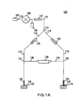
- FIG. 1A is a diagram of a gas gauge proximity sensor, according to an embodiment of the present invention.
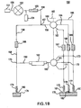
- FIG. 1B is a diagram of a gas gauge proximity sensor with multiple measurement branches, according to an embodiment of the present invention.
- FIG. 2 is a diagram that provides a cross sectional view of a restrictor, according to an embodiment of the present invention.
- FIG. 3A is a diagram that shows the basic characteristics of a nozzle.
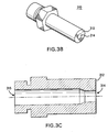
- FIG. 3B is a diagram that shows a perspective view of a nozzle that may be used in a reference probe or a measurement probe, according to an embodiment of the present invention.
- FIG. 3C is a diagram that shows a cross sectional view of the nozzle illustrated in FIG. 3B, according to an embodiment of the present invention.
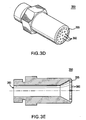
- FIG. 3D is a diagram that shows a perspective view of a shower-head nozzle that may be used in a reference probe or a measurement probe, according to an embodiment of the present invention.
- FIG. 3E is a diagram that shows a cross sectional view of the nozzle illustrated in FIG 3D, according to an embodiment of the present invention.
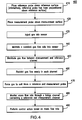
- FIG. 4 is a flowchart diagram that shows a method for using a gas gauge proximity sensor to detect very small distances and perform a control action, according to an embodiment of the present invention.
- FIG. 5 is a sensitivity plot that illustrates test results for nozzles with different dimensions, according to an embodiment of the present invention.
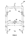
- FIG. 6 is a schematic diagram of a gas gauge proximity sensor in a bridge configuration according to an embodiment of the present invention whose operation is simulated by a one-dimensional model.
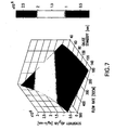
- FIG. 7 is a sensitivity plot that illustrates simulation results as a function of air mass flow rate and gauge nozzle standoff.
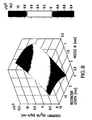
- FIG. 8 is a sensitivity plot that illustrates simulation results as a function of nozzle inner diameter (ID) and length of the porous restrictors.
- FIG. 1A illustrates gas gauge proximity sensor 100, according to an embodiment of the present invention.
- Gas gauge proximity sensor 100 includes mass flow controller 106, central channel 112, measurement channel 116, reference channel 118, measurement channel restrictor 120, reference channel restrictor 122, measurement probe 128, reference probe 130, bridge channel 136 and mass flow sensor 138.
- Gas supply 102 injects gas at a desired pressure into gas gauge proximity sensor 100.
- Central channel 112 connects gas supply 102 to mass flow controller 106 and then terminates at junction 114.
- Mass flow controller 106 maintains a constant flow rate within gas gauge proximity sensor 100. Gas is forced out from mass flow controller 106 through a porous snubber 110, with an accumulator 108 affixed to channel 112. Snubber 110 reduces gas turbulence introduced by the gas supply 102, and its use is optional. Upon exiting snubber 110, gas travels through central channel 112 to junction 114. Central channel 112 terminates at junction 114 and divides into measurement channel 116 and reference channel 118. Mass flow controller 106 injects gas at a sufficiently low rate to provide laminar and incompressible fluid flow throughout the system to minimize the production of undesired pneumatic noise.
- Bridge channel 136 is coupled between measurement channel 116 and reference channel 118. Bridge channel 136 connects to measurement channel 116 at junction 124. Bridge channel 136 connects to reference channel 118 at junction 126. In one example, the distance between junction 114 and junction 124 and the distance between junction 114 and junction 126 are equal.
- Channels 112, 116, 118, and 136 can be made up of conduits (tubes, pipes, etc.) or any other type of structure that can contain and guide gas flow through sensor 100.
- the channels do not have sharp bends, irregularities or unnecessary obstructions that may introduce pneumatic noise, for example, by producing local turbulence or flow instability.
- the overall lengths of measurement channel 116 and reference channel 118 can be equal or in other examples can be unequal.
- Reference channel 118 terminates into reference probe 130.
- measurement channel 116 terminates into measurement probe 128.
- Reference probe 130 is positioned above reference surface 134.
- Measurement probe 128 is positioned above measurement surface 132.
- measurement surface 132 is often a semiconductor wafer or stage supporting a wafer.
- Reference surface 134 can be a flat metal plate, but is not limited to this example.
- Gas injected by gas supply 102 is emitted from each of the probes 128, 130 and impinges upon measurement surface 132 and reference surface 134.
- Nozzles are provided in measurement probe 128 and reference probe 130. Example nozzles are described further below with respect to FIGs. 3A-3E. As stated above, the distance between a nozzle and a corresponding measurement or reference surface is referred to as a standoff.
- reference probe 130 is positioned above a fixed reference surface 134 with a known reference standoff 142.
- Measurement probe 128 is positioned above measurement surface 132 with an unknown measurement standoff 140.
- the known reference standoff 142 is set to a desired constant value representing an optimum standoff.
- the backpressure upstream of the measurement probe 128 is a function of the unknown measurement standoff 140; and the backpressure upstream of the reference probe 130 is a function of the known reference standoff 142. If standoffs 140 and 142 are equal, the configuration is symmetrical and the bridge is balanced. Consequently, there is no gas flow through bridging channel 136.
- the measurement standoff 140 and reference standoff 142 are different, the resulting pressure difference between the measurement channel 116 and the reference channel 118 induces a flow of gas through mass flow sensor 138.
- Mass flow sensor 138 is located along bridge channel 136, preferably at a central point. Mass flow sensor 136 senses gas flows induced by pressure differences between measurement channel 116 and reference channel 118. These pressure differences occur as a result of changes in the vertical positioning of measurement surface 132. For a symmetric bridge, when measurement standoff 140 and reference standoff 142 are equal, the standoff is the same for both of the probes 128, 130 compared to surfaces 132, 134. Mass flow sensor 138 will detect no mass flow, since there will be no pressure difference between the measurement and reference channels. Differences between measurement standoff 140 and reference standoff 142 will lead to different pressures in measurement channel 116 and reference channel 118. Proper offsets can be introduced for an asymmetric arrangement.
- Mass flow sensor 138 senses gas flow induced by a pressure difference or imbalance.
- a pressure difference causes a gas flow, the rate of which is a unique function of the measurement standoff 140.
- the difference between gas pressures in the measurement channel 116 and the reference channel 118 is a function of the difference between the magnitudes of standoffs 140 and 142. If reference standoff 142 is set to a known standoff, the difference between gas pressures in the measurement channel 116 and the reference channel 118 is a function of the size of measurement standoff 140 (that is, the unknown standoff in the z direction between measurement surface 132 and measurement probe 128).
- Mass flow sensor 138 detects gas flow in either direction through bridge channel 136. Because of the bridge configuration, gas flow occurs through bridge channel 136 only when pressure differences between channels 116, 118 occur. When a pressure imbalance exists, mass flow sensor 138 detects a resulting gas flow, and can initiate an appropriate control function. Mass flow sensor 138 can provide an indication of a sensed flow through a visual display or audio indication. Alternatively, in place of a mass flow sensor, a differential pressure sensor may be used. The differential pressure sensor measures the difference in pressure between the two channels, which is a function of the difference between the measurement and reference standoffs.
- the control function may be to calculate the exact gap differences.
- the control function may be to increase or decrease the size of measurement gap 140. This is accomplished by moving the measurement surface 132 relative to measurement probe 128 until the pressure difference is sufficiently close to zero, which occurs when there is no longer a difference between the standoffs from measurement surface 132 and reference surface 134.
- FIG. 1A illustrates at least three elements of the present invention that reduce gas turbulence and other pneumatic noise to enable the present invention to achieve nanometer accuracy.
- These elements, mass flow rate controller 106, snubber 110 and restrictors 120, 122, may all be used within an embodiment of the present invention or in any combination depending on the sensitivity desired. For example, if an application required very precise sensitivity, all elements may be used. Alternatively, if an application required less sensitivity, perhaps only snubber 110 would be needed with porous restrictors 120 and 122 replaced by orifices. As a result, the present invention provides a flexible approach to cost effectively meet a particular application's requirements.
- mass flow rate controller 106 and/or snubber 110 may be used within the systems disclosed in U.S. Patents 4,953,388 and 4,550,592 to significantly enhance their sensitivity.
- FIG. 1B illustrates gas gauge proximity sensor 150, according to an embodiment of the present invention.
- Gas gauge proximity sensor 150 includes many of the same components as gas gauge proximity sensor 100 with similar principles of operation. The difference between the two sensors is that gas gauge proximity sensor 150 has three measurement branches which are comparable to the one measurement channel included within gas gauge proximity sensor 100. Three measurement branches are shown for ease of illustration, and the present invention is not limited to three measurement branches. Any number of measurement branches from two or more may be used.
- Gas gauge proximity sensor 150 includes mass flow controller 153, central channel 156, reference channel 158, reference channel restrictor 166, reference probe 174, bridge channel 190 and mass flow sensor 192.
- gas gauge proximity sensor 150 includes measurement channel 159.
- Measurement channel 159 divides into three measurement branches 163, 164 and 165.
- Measurement branch 163 includes measurement branch restrictor 167 and measurement probe 175.
- Measurement branch 164 includes measurement branch restrictor 168 and measurement probe 176.
- Measurement branch 165 includes measurement branch restrictor 169 and measurement probe 177.
- gas gauge proximity sensor 150 includes measurement channel switching device 160, bridge channel switching device 161, and switching device lever 162.
- Gas supply 151 injects gas at a desired pressure into gas gauge proximity sensor 150.
- Central channel 156 connects gas supply 151 to mass flow controller 153 and then terminates at a junction 157.
- Mass flow controller 153 maintains a constant flow rate within gas gauge proximity sensor 150.
- Mass flow controller 153 injects gas at a sufficiently low rate to provide laminar and incompressible fluid flow throughout the system to minimize the production of undesired pneumatic noise.
- Gas is forced out from mass flow controller 153 through porous snubber 155, with accumulator 154 affixed to channel 156. Snubber 155 reduces gas turbulence introduced by the gas supply 151, and its use is optional.
- gas Upon exiting snubber 155, gas travels through central channel 156 to junction 157.
- Central channel 156 terminates at junction 157 and divides into measurement channel 159 and reference channel 158.
- Measurement channel 159 terminates into measurement channel switching device 160.
- Measurement channel switching device 160 can be a scanning valve or other type of switching device that serves to switch a measurement channel to one of several measurement branches that are also connected to measurement channel switching device 160.
- the physical characteristics of a measurement branch are the same as the physical characteristics of a measurement channel.
- Measurement channel switching device 160 is operated by switching device lever 162. Switching device lever 162 controls which measurement branch 163, 164 or 165 is connected to the measurement channel 159 through measurement channel switching device 160.
- Bridge channel 190 is coupled between reference channel 158 and one of the three measurement branches 163, 164 or 165 through bridge channel switching device 161.
- Bridge channel 190 connects to reference channel 158 at junction 170.
- Bridge channel 190 terminates in bridge channel switching device 161.
- Bridge channel switching device 161 can be a scanning valve or other type of switching device that serves to switch a bridge channel to one of the measurement branches. In one example shown in FIG 1B, three measurement branches 163, 164 and 165 are connected to bridge channel switching device 161 at junctions 171, 172, and 173 respectively.
- Switching device lever 162 controls which measurement branch 163, 164, or 165 is connected to the bridge channel through bridge channel switching device 161. Switching lever 162 controls both measurement channel switching device 160 and bridge channel switching device 161, such that the same measurement branch will be connected to both measurement channel 159 and bridge channel 190. Alternatively, two independent switching levers can be used.
- the distance between junction 157 and junction 170 and the distance between junction 157 and junction 171, 172 or 173 are equal.
- Channels 156, 158, 159, and 190, and branches 163, 164, and 165 can be made up of conduits (tubes, pipes, etc.) or any other type of structure that can contain and guide gas flow through sensor 150.
- the channels and branches do not have sharp bends, irregularities or unnecessary obstructions that may introduce pneumatic noise, for example, by producing local turbulence or flow instability.
- the overall lengths of reference channel 158 and measurement channel 159 plus one of measurement branches 163, 164 or 165 can be equal or in other examples can be unequal.
- Reference channel 158 terminates into reference probe 174.
- measurement branches 163, 164 and 165 terminate into measurement probes 175, 176 and 177 respectively.
- Reference probe 174 is positioned above reference surface 178.
- Measurement probes 175, 176 and 177 are positioned above measurement surface 179.
- measurement surface 179 is often a semiconductor wafer or stage supporting a wafer.
- Reference surface 178 can be a flat metal plate, but is not limited to this example.
- Gas injected by gas supply 151 is emitted from reference probe 174 and impinges upon reference surface 178.
- gas injected by gas supply 151 is emitted from one of the three measurement probes 175, 176 or 177 and impinges on measurement surface 179.
- the position of switching device lever 162 determines from which measurement probe gas is emitted.
- Nozzles are provided in probes 174, 175, 176 and 177. Example nozzles are described further below with respect to FIGs. 3A-3E. As stated above, the distance between a nozzle and a corresponding measurement or reference surface is referred to as a standoff.
- reference probe 174 is positioned above a fixed reference surface 178 with a known reference standoff 180.
- Measurement probes 175, 176 and 177 are positioned above measurement surface 179 with unknown measurement standoffs 181, 182 and 183.
- Measurement standoffs 181, 182 and 183 may be equal or they may be unequal where the topography of a measurement surface varies from region to region.
- the known reference standoff 180 is set to a desired constant value representing an optimum standoff. With such an arrangement, the backpressure upstream from measurement probe 175, 176 or 177 that is in use is a function of the unknown measurement standoff 181, 182 or 183 respectively; and the backpressure upstream of the reference probe 174 is a function of the known reference standoff 180.
- reference standoff 180 and the measurement standoff 181, 182 or 183 that is being used are equal, the configuration is symmetrical and the bridge is balanced. Consequently, there is no gas flow through bridge channel 174.
- the reference standoff 180 and the measurement standoff 181, 182 or 183 corresponding to the measurement branch in use is different, the resulting pressure difference between the reference channel 158 and the measurement branch 163, 164 or 165 that is being used induces a flow of gas through bridge channel 190.
- Mass flow sensor 192 is located along bridge channel 190, preferably at a central point. Mass flow sensor 192 senses gas flows induced by pressure differences between reference channel 158 and the measurement branch 163, 164 or 165 that is being used. These pressure differences occur as a result of changes in the vertical positioning of measurement surface 179. For a symmetric bridge, when reference standoff 180 and a measurement standoff 181, 182 or 183 corresponding to the measurement branch that is being used are equal, mass flow sensor 192 will detect no mass flow, since there will be no pressure difference between the measurement branch in use and the reference channel.
- Mass flow sensor 192 senses gas flow induced by a pressure difference or imbalance.
- a pressure difference causes a gas flow, the rate of which is a unique function of a measurement standoff 181, 182 or 183.
- the difference between gas pressures in a measurement branch 163, 164 or 165 and reference channel 158 is a function of the difference between reference standoff 180 and a measurement standoff 181, 182 or 183 corresponding to the measurement branch that is being used.
- reference standoff 180 is set to a known standoff
- the difference between gas pressures in a measurement branch 163, 164 or 165 that is being used and reference channel 158 is a function of the size of a measurement standoff (that is, the unknown standoff in the z direction between measurement surface 179 and a measurement probe 175, 176 or 177 that is being used).
- Mass flow sensor 192 detects gas flow in either direction through bridge channel 190. Because of the bridge configuration, gas flow occurs through bridge channel 190 only when pressure differences occur between reference channel 158 and a measurement branch 163, 164 or 165 that is being used. When a pressure imbalance exists, mass flow sensor 192 detects a resulting gas flow, and can initiate an appropriate control function. Mass flow sensor 192 can provide an indication of a sensed flow through a visual display or audio indication. Alternatively, in place of a mass flow sensor, a differential pressure sensor may be used. The differential pressure sensor measures the difference in pressure between the reference channel and a measurement branch, which is a function of the difference between a measurement standoff and the reference standoff.
- the control function may be to calculate the exact gap differences.
- the control function may be to increase or decrease the size of a measurement standoff 181, 182 or 183. This is accomplished by moving the measurement surface relative to a measurement probe until the pressure difference is sufficiently close to zero, which occurs when there is no longer a difference between the standoffs from a measurement surface and reference surface 178.
- FIG. 1B illustrates at least three elements of the present invention that reduce gas turbulence and other pneumatic noise to enable the present invention to achieve nanometer accuracy.
- These elements, mass flow rate controller 153, snubber 155 and restrictors 166, 167, 168 and 169 may all be used within an embodiment of the present invention or in any combination depending on the sensitivity desired. For example, if an application required very precise sensitivity, all elements may be used. Alternatively, if an application required less sensitivity, perhaps only snubber 155 would be needed with porous restrictors 166, 167, 168, and 169 replaced by orifices. As a result, the present invention provides a flexible approach to cost effectively meet a particular application's requirements.
- measurement channel 116 and reference channel 118 contain restrictors 120, 122.
- Each restrictor 120, 122 restricts the flow of gas traveling through the respective measurement channel 116 and reference channel 118.
- Measurement channel restrictor 120 is located within measurement channel 116 between junction 114 and junction 124.
- reference channel restrictor 122 is located within reference channel 118 between junction 114 and junction 126.
- the distance from junction 114 to measurement channel restrictor 120 and the distance from junction 114 to reference channel restrictor 122 are equal. In other examples, the distances are not equal. There is no inherent requirement that the sensor be symmetrical, however, the sensor is easier to use if it is geometrically symmetrical.
- each restrictor 120, 122 consists of a porous material, such as polyethylene or sintered stainless steel.
- FIG. 2 provides a cross-sectional image of restrictor 120 having porous material 210 through which a gas flow 200 passes.
- Measurement channel restrictor 120 and reference channel restrictor 122 have substantially the same dimensions and permeability characteristics. Restrictors typically range in length from 2 to 15mm, but are not limited to these lengths. Measurement channel restrictor 120 and reference channel restrictor 122 restrict gas flow evenly across the cross-sectional areas of the channels 116, 118.
- porous material restrictors provide a significant reduction in turbulence and associated pneumatic noise in gas flow compared to the amount of turbulence and noise introduced by restrictors that use a single orifice bored out of a solid, non-porous material.
- porous restrictors 166, 167, 168 and 169 with above mentioned characteristics are also used to achieve these advantages.
- the restrictors serve two key functions. First, they mitigate the pressure and flow disturbances present in gas gauge proximity sensor 100, most notably disturbances generated by mass flow controller 110 or sources of acoustic pick-up. Second, they serve as the required resistive elements within the bridge.
- channel 112 contains snubber 110. Similar to the operation of a restrictor, snubber 110 reduces gas turbulence introduced by gas supply 102 and isolates the mass flow sensor from acoustic pick-up in the upstream part of the gas gauge sensor. Snubber 110 is located within channel 112 between accumulator 108 and junction 114. According to a further feature of the present invention, snubber 110 consists of a porous material, such as polyethylene or sintered stainless steel. The inventors discovered that porous material snubbers provide a significant reduction in turbulence and associated pneumatic noise in gas flow. Snubber 155 used within gas gauge proximity sensor 150 has the same characteristics as Snubber 110 and is used to achieve the same benefits.
- nozzles may be used as reference probe 130 and measurement probe 128 depending on a particular application.
- different types of nozzles may be used in gas gauge proximity sensor 150 for reference probe 174 and measurement probes 181, 182 and 183.
- the choice of nozzle type depends on the footprint (measurement area) that is required.
- the basic configuration of the gas gauge nozzle 300 is characterized by a flat end surface that is parallel to the surface of the measurement surface, as shown in FIG. 3A.
- the geometry of a nozzle is determined by the gauge standoff, h , and the inner diameter, d .
- the dependence of the nozzle pressure drop on the nozzle outer diameter D is weak, if D is sufficiently large.
- the remaining physical parameters are: Q m - mass flow rate of the gas, and ⁇ p - pressure drop across the nozzle.
- the gas is characterized by the density, ⁇ , and dynamic viscosity, ⁇ .
- a relationship is sought between non-dimensional parameters: ⁇ p 1 2 ⁇ u 2 , the Reynolds Number, Re , and h / d , where the radial velocity, u , is taken at the entrance to the cylindrical region between the nozzle face and the wafer surface.
- FIG. 5 plots the data points for these tests.
- Eq. (3) provides a relationship between the two principal variables, ⁇ p and h , as the remaining variables would be typically constant for a practical system. This relationship facilitates the development of nozzle types for different applications, requiring different sensitivities.
- FIGS. 3B and 3C illustrate a nozzle 310 that may be used as a reference probe or measurement probe, according to an embodiment of the present invention.
- Nozzle 310 includes front surface 312, gas bore front opening 314, and gas bore rear opening 315.
- Nozzle 310 is affixed to both measurement channel 116 and reference channel 118. In one embodiment, two identical nozzles 310 serve as measurement probe 128 and reference probe 130. In principle, the nozzles do not need to be identical.
- Nozzle 310 is affixed to measurement channel 116. Front surface 312 should be parallel to measurement surface 132. Gas travelling through measurement channel 116 enters nozzle 310 through gas bore rear opening 315 and exits through gas bore front opening 314. Similarly, nozzle 310 is affixed to reference channel 118. Front surface 312 is parallel to reference surface 134. Gas travelling through reference channel 118 enters nozzle 310 through gas bore rear opening 315 and exits through gas bore front opening 314.
- the diameter of gas bore front opening 314 can vary depending upon a particular application.
- the inner diameter of gas bore front opening 314 is between approximately 0.5 and 2.5 millimeters (mm).
- Example sensitivity analysis results of a gas gauge proximity sensor model having porous flow restrictors and single gas bore nozzles at the probes are described further below with respect to FIGs. 6-8.
- FIGS. 3D and 3E illustrate shower-head nozzle 350 that may be used as the reference and measurement probes, according to an embodiment of the present invention.
- shower-head nozzle 350 includes front surface 355, a plurality of gas bore front openings 360, and a gas bore rear opening 365.
- the multiple gas bore front openings distribute pressure across a wider area of measurement surface 132 than nozzle 310.
- a shower-head nozzle is principally used for lowering spatial resolution to evenly integrate proximity measurements over a wider spatial area.
- An alternative approach would be to use a nozzle that contains a porous filter.
- a shower-head nozzle 350 is affixed to both measurement channel 116 and reference channel 118.
- two identical shower-head nozzles 350 serve as measurement probe 128 and reference probe 130. In principle, the nozzles do not need to be identical.
- shower-head nozzle 350 is affixed to measurement channel 116.
- Front surface 355 is parallel to measurement surface 132. Gas travelling through measurement channel 116 enters shower-head nozzle 350 through gas bore rear opening 365 and exits through a plurality of gas bore front openings 360.
- shower-head nozzle 350 is affixed to reference channel 118.
- Front surface 355 is parallel to reference surface 134.
- Gas travelling through reference channel 122 enters shower-head nozzle 350 through gas bore rear opening 365 and exits through a plurality of gas bore front openings 360.
- the use of nozzles has been explained with reference to gas gauge proximity sensor 100 for ease of illustration.
- Each of the nozzle types may also be used with gas gauge proximity sensor 150, wherein the nozzles would be affixed to each of the measurement branch probes and the reference channel probe.
- method 400 for using gas flow to detect very small distances and perform a control action (steps 410-470).
- method 400 is described with respect to gas gauge proximity sensor 100.
- method 400 is not necessarily limited by the structure of sensor 100, and can be implemented with gas gauge proximity sensor 150 or a sensor with a different structure.
- step 410 an operator or mechanical device places a reference probe above a reference surface.
- a reference surface For example, an operator or mechanical device positions reference probe 130 above reference surface 134 with known reference standoff 142.
- the reference standoff can be arranged within the sensor assembly, that is, internal to the sensor assembly. The reference standoff is pre-adjusted to a particular value, which typically would be maintained constant.
- an operator or mechanical device places a measurement probe above a measurement surface. For example, an operator or mechanical device positions measurement probe 128 above measurement surface 132 to form measurement gap 140.
- step 430 gas is injected into a sensor.
- a measurement gas is injected into gas gauge proximity sensor 100 with a constant mass flow rate.
- step 440 a constant gas flow rate into a sensor is maintained.
- mass flow controller 106 maintains a constant gas flow rate.
- step 450 gas flow is distributed between measurement and reference channels.
- gas gauge proximity sensor 100 causes the flow of the measurement gas to be evenly distributed between measurement channel 116 and reference channel 118.
- step 460 gas flow in the measurement channel and the reference channel is restricted evenly across cross-sectional areas of the channels.
- Measurement channel restrictor 120 and reference channel restrictor 122 restrict the flow of gas to reduce pneumatic noise and serve as a resistive element in gas gauge proximity sensor 100.
- step 470 gas is forced to exit from a reference and measurement probe.
- gas gauge proximity sensor 100 forces gas to exit measurement probe 128 and reference probe 130.
- step 480 a flow of gas is monitored through a bridge channel connecting a reference channel and a measurement channel.
- a control action is performed based on a pressure difference between the reference and measurement channel.
- mass flow sensor 138 monitors mass flow rate between measurement channel 116 and reference channel 118. Based on the mass flow rate, mass flow sensor 138 initiates a control action.
- Such control action may include providing an indication of the sensed mass flow, sending a message indicating a sensed mass flow, or initiating a servo control action to reposition the location of the measurement surface relative to the reference surface until no mass flow or a fixed reference value of mass flow is sensed.
- the above method may be adapted to use with a sensor that has multiple measurement branches, such as gas gauge proximity sensor 150.
- a sensor that has multiple measurement branches, such as gas gauge proximity sensor 150.
- an additional step may be incorporated that includes switching from the use of one measurement branch to another measurement branch.
- a gas gauge proximity sensor 150 can also better facilitate the mapping of the topography of a measurement surface. This mapping may be accomplished through the principles described in the above method, wherein topography measurements are taken over a particular region of a work surface using one of the measurement branches. If a topography mapping is desired of a different region, the flow of gas may be switched to a different measurement branch to map the topography of a different region. Because of limitations that may exist in the ability to move a measurement surface, a proximity sensor with multiple branches can be used in some instances to more readily map the topography of a measurement surface than a proximity sensor with only one measurement channel.
- a method for mapping the topography includes injecting gas into a proximity sensor, such as gas gauge proximity sensor 150, and measuring the topography of a region of a measurement surface by taking a series of measurements using one of the measurement branches. Upon completing the mapping of the region that can be mapped by a particular measurement branch, the proximity sensor would be switched to a different measurement branch to repeat the mapping process for the region reached by that measurement branch. The process would be repeated until the surface for which a topography mapping is desired is completed.
- the measurement surface may be a semiconductor wafer or other measurement surface for which a topography mapping is desired.
- the present invention has been described with respect to FIGs. 1-4 with reference to a gas.
- the gas is air.
- the present invention is not limited to air.
- gases or combinations of gases can be used.
- a gas having a reduced moisture content or an inert gas may be used depending on the surface being measured.
- a low moisture content gas or inert gas is less likely than air to react with the surface being measured.
- FIG. 6 is a schematic diagram of a gas gauge proximity sensor 600 (also referred to as a "bridge” 600) whose operation is described with respect to the one-dimensional model.
- gas gauge 600 includes five legs l1 - l5, two porous flow restrictors 630, 635, measurement nozzle 640, reference nozzle 645, and a mass flow sensor 665.
- Leg l1 extends from junction 114 to junction 124.
- Leg l2 extends from junction 114 to junction 126.
- Leg 13 extends between junctions 124 and 126.
- Leg l4 extends from junction 124 to measurement nozzle 640.
- Leg l5 extends from junction 126 to reference nozzle 645.
- Porous flow restrictor 630 is provided along leg l1.
- Porous flow restrictor 635 is provided along leg l2.
- Measurement nozzle 640 is provided at the end of leg l4.
- Reference nozzle 645 is provided at the end of leg l5.
- Mass flow sensor 665 is provided along leg l3.
- the 1-D model of the gas gauge aids the development process of the gas gauge.
- the model allows for a selection of the gas gauge physical parameters and yields a quick assessment of the gas gauge performance under steady state operation.
- the pressure loss in a porous restrictor is modeled after Darcy's law. See, A. Bejan, Convective Heat Transfer , Chapter 10 John Wiley & Sons, 1984.
- the restrictors 630, 635 are of the length l R and have the same diameter as the tube in legs l1 and l2 that results in the same averaged velocity w i .
- the constants ⁇ and K are the dynamic viscosity of fluid (air) and the permeability of the porous material, correspondingly.
- the pressure drop can be expressed in terms of the mass flow rate Q i .
- the coefficient a was determined experimentally showing good agreement with technical specifications of the mass flow meter.
- the second component of the sum in equation (16) represents a semi-empirical, similarity-based model for the pressure drop across a nozzle.
- Results of the simulation are shown in terms of sensitivity plots as a function of the mass flow rate and the gauge nozzle standoff (FIG. 7) and as a function of the nozzle ID and the length of the porous restrictors (FIG. 8).
- FIG. 7 illustrates a sensitivity plot as a function of the mass flow rate and gauge nozzle standoff for a gauge with a nozzle having a 1.14mm internal diameter (ID) and a restrictor that is 7 mm in length.
- gauge standoffs ranging from 40 to 140mm were used and flow rates ranging from 100 to 500 sccm.
- the plot shows that as the gauge standoff becomes smaller, the sensitivity of the gauge to detect changes in the difference between a reference standoff and a measurement standoff increases.
- the plot shows that the rate of sensitivity increase as the gauge standoff becomes smaller is more pronounced at higher flow rates.
- the sensitivity also increases.
- FIG. 8 illustrates a sensitivity plot as a function of the nozzle ID and restrictor length when the measurement standoff is 100mm and the flow rate is 200 sccm.
- nozzles with IDs ranging from 0.5 to 2.5mm were used and restrictors with lengths ranging from 5 to 15mm were used.
- the plot shows that as the nozzle ID becomes smaller, the sensitivity of the gauge to detect changes in the difference between a reference standoff and a measurement standoff increases.
- the plot further shows that the rate of sensitivity increase as the nozzle ID becomes smaller, remains relatively consistent over the different restrictor lengths.
- the plot illustrates a relatively small dependence of the gauge sensitivity on the length of both restrictors.
- the sensitivity dependence on the flow rate and the standoff is relatively major. It increases (linearly) with the flow rate and decreases with the standoff at a faster than linear rate.
- the sensitivity dependence on the two other parameters (nozzle ID and the restrictor length) is considerably weaker within practical limits of the variability of these parameters. It decreases with the ID of the nozzle and increases with the restrictor length.
- the data show that the increasing the flow rate can be used to improve the gauge sensitivity as long as this would not cause an increase in the aerodynamic noise. Transition to turbulence would certainly be a practical limitation on the maximum flow rate that can be used.
Applications Claiming Priority (2)
| Application Number | Priority Date | Filing Date | Title |
|---|---|---|---|
| US322768 | 1989-03-13 | ||
| US10/322,768 US7010958B2 (en) | 2002-12-19 | 2002-12-19 | High-resolution gas gauge proximity sensor |
Publications (2)
| Publication Number | Publication Date |
|---|---|
| EP1431709A2 true EP1431709A2 (fr) | 2004-06-23 |
| EP1431709A3 EP1431709A3 (fr) | 2004-09-15 |
Family
ID=32393023
Family Applications (2)
| Application Number | Title | Priority Date | Filing Date |
|---|---|---|---|
| EP03028485A Withdrawn EP1431709A3 (fr) | 2002-12-19 | 2003-12-12 | Capteur de proximité à haute resolution avec flux de gaz |
| EP08018579A Withdrawn EP2023080A2 (fr) | 2002-12-19 | 2003-12-16 | Capteur de proximité de flux liquide à utiliser dans une lithographie par immersion |
Family Applications After (1)
| Application Number | Title | Priority Date | Filing Date |
|---|---|---|---|
| EP08018579A Withdrawn EP2023080A2 (fr) | 2002-12-19 | 2003-12-16 | Capteur de proximité de flux liquide à utiliser dans une lithographie par immersion |
Country Status (6)
| Country | Link |
|---|---|
| US (3) | US7010958B2 (fr) |
| EP (2) | EP1431709A3 (fr) |
| JP (1) | JP3975195B2 (fr) |
| KR (1) | KR100754043B1 (fr) |
| CN (1) | CN100427881C (fr) |
| TW (2) | TWI291547B (fr) |
Cited By (5)
| Publication number | Priority date | Publication date | Assignee | Title |
|---|---|---|---|---|
| US7021121B2 (en) * | 2004-05-27 | 2006-04-04 | Asml Holding N.V. | Gas gauge proximity sensor with a modulated gas flow |
| EP2009391A1 (fr) | 2007-06-27 | 2008-12-31 | ASML Holding N.V. | Capteur pneumatique avec sensibilité à la pressure augmenté en utilisant la rugosité de surface de l'orifice |
| WO2009100987A1 (fr) * | 2008-02-14 | 2009-08-20 | Burger Gmbh | Dispositif et procédé de mesure géométrique d'une pièce à usiner |
| WO2012174273A1 (fr) * | 2011-06-15 | 2012-12-20 | Nikon Corporation | Jauges de fluide à faible bruit |
| WO2016202621A1 (fr) * | 2015-06-18 | 2016-12-22 | Asml Holding N.V. | Appareil comprenant une jauge de gaz et procédé de fonctionnement correspondant |
Families Citing this family (141)
| Publication number | Priority date | Publication date | Assignee | Title |
|---|---|---|---|---|
| SG121819A1 (en) * | 2002-11-12 | 2006-05-26 | Asml Netherlands Bv | Lithographic apparatus and device manufacturing method |
| US9482966B2 (en) | 2002-11-12 | 2016-11-01 | Asml Netherlands B.V. | Lithographic apparatus and device manufacturing method |
| US10503084B2 (en) | 2002-11-12 | 2019-12-10 | Asml Netherlands B.V. | Lithographic apparatus and device manufacturing method |
| JP3977324B2 (ja) | 2002-11-12 | 2007-09-19 | エーエスエムエル ネザーランズ ビー.ブイ. | リソグラフィ装置 |
| US7372541B2 (en) * | 2002-11-12 | 2008-05-13 | Asml Netherlands B.V. | Lithographic apparatus and device manufacturing method |
| CN101852993A (zh) * | 2002-12-10 | 2010-10-06 | 株式会社尼康 | 曝光装置和器件制造方法 |
| JP4352874B2 (ja) * | 2002-12-10 | 2009-10-28 | 株式会社ニコン | 露光装置及びデバイス製造方法 |
| US7242455B2 (en) * | 2002-12-10 | 2007-07-10 | Nikon Corporation | Exposure apparatus and method for producing device |
| KR101037057B1 (ko) * | 2002-12-10 | 2011-05-26 | 가부시키가이샤 니콘 | 노광 장치 및 디바이스 제조 방법 |
| AU2003289271A1 (en) * | 2002-12-10 | 2004-06-30 | Nikon Corporation | Exposure apparatus, exposure method and method for manufacturing device |
| US7948604B2 (en) * | 2002-12-10 | 2011-05-24 | Nikon Corporation | Exposure apparatus and method for producing device |
| CN101872135B (zh) * | 2002-12-10 | 2013-07-31 | 株式会社尼康 | 曝光设备和器件制造法 |
| SG107157A1 (en) * | 2002-12-19 | 2004-11-29 | Asml Holding Nv | Liquid flow proximity sensor for use in immersion lithography |
| DE10261775A1 (de) * | 2002-12-20 | 2004-07-01 | Carl Zeiss Smt Ag | Vorrichtung zur optischen Vermessung eines Abbildungssystems |
| EP2945184B1 (fr) * | 2003-02-26 | 2017-06-28 | Nikon Corporation | Appareil d'exposition, procédé d'exposition et procédé de production du dispositif |
| WO2004086470A1 (fr) * | 2003-03-25 | 2004-10-07 | Nikon Corporation | Systeme d'exposition et procede de production de dispositifs |
| JP4902201B2 (ja) * | 2003-04-07 | 2012-03-21 | 株式会社ニコン | 露光装置、露光方法及びデバイス製造方法 |
| KR20110104084A (ko) * | 2003-04-09 | 2011-09-21 | 가부시키가이샤 니콘 | 액침 리소그래피 유체 제어 시스템 |
| EP3062152B1 (fr) | 2003-04-10 | 2017-12-20 | Nikon Corporation | Système environnemental comprenant une zone de transport pour un appareil de lithographie par immersion |
| WO2004090633A2 (fr) * | 2003-04-10 | 2004-10-21 | Nikon Corporation | Systeme environnemental avec un element electro-osmotique pour un appareil lithographique a immersion |
| CN103383527B (zh) | 2003-04-10 | 2015-10-28 | 株式会社尼康 | 包括用于沉浸光刻装置的真空清除的环境系统 |
| EP2921905B1 (fr) | 2003-04-10 | 2017-12-27 | Nikon Corporation | Trajet d'écoulement permettant de recueillir un liquide pour un appareil de lithographie par immersion |
| KR101533206B1 (ko) | 2003-04-11 | 2015-07-01 | 가부시키가이샤 니콘 | 액침 리소그래피 머신에서 웨이퍼 교환동안 투영 렌즈 아래의 갭에서 액침 액체를 유지하는 장치 및 방법 |
| JP4582089B2 (ja) | 2003-04-11 | 2010-11-17 | 株式会社ニコン | 液浸リソグラフィ用の液体噴射回収システム |
| WO2004093130A2 (fr) | 2003-04-11 | 2004-10-28 | Nikon Corporation | Procede de nettoyage pour dispositif optique utilise dans un processus de lithographie par immersion |
| SG152078A1 (en) * | 2003-04-17 | 2009-05-29 | Nikon Corp | Optical arrangement of autofocus elements for use with immersion lithography |
| TWI295414B (en) | 2003-05-13 | 2008-04-01 | Asml Netherlands Bv | Lithographic apparatus and device manufacturing method |
| CN100437358C (zh) * | 2003-05-15 | 2008-11-26 | 株式会社尼康 | 曝光装置及器件制造方法 |
| TW201806001A (zh) * | 2003-05-23 | 2018-02-16 | 尼康股份有限公司 | 曝光裝置及元件製造方法 |
| TW201415536A (zh) | 2003-05-23 | 2014-04-16 | 尼康股份有限公司 | 曝光方法及曝光裝置以及元件製造方法 |
| KR20180122033A (ko) * | 2003-05-28 | 2018-11-09 | 가부시키가이샤 니콘 | 노광 방법, 노광 장치, 및 디바이스 제조 방법 |
| US7213963B2 (en) | 2003-06-09 | 2007-05-08 | Asml Netherlands B.V. | Lithographic apparatus and device manufacturing method |
| EP2261742A3 (fr) | 2003-06-11 | 2011-05-25 | ASML Netherlands BV | Appareil lithographique et méthode de fabrication d'un dispositif |
| US7317504B2 (en) * | 2004-04-08 | 2008-01-08 | Asml Netherlands B.V. | Lithographic apparatus and device manufacturing method |
| TW201445617A (zh) * | 2003-06-13 | 2014-12-01 | 尼康股份有限公司 | 基板載台、曝光裝置 |
| KR101419663B1 (ko) | 2003-06-19 | 2014-07-15 | 가부시키가이샤 니콘 | 노광 장치 및 디바이스 제조방법 |
| US6867844B2 (en) | 2003-06-19 | 2005-03-15 | Asml Holding N.V. | Immersion photolithography system and method using microchannel nozzles |
| EP1491956B1 (fr) | 2003-06-27 | 2006-09-06 | ASML Netherlands B.V. | Appareil lithographique et méthode de fabrication d'un dispositif |
| US6809794B1 (en) * | 2003-06-27 | 2004-10-26 | Asml Holding N.V. | Immersion photolithography system and method using inverted wafer-projection optics interface |
| WO2005006026A2 (fr) * | 2003-07-01 | 2005-01-20 | Nikon Corporation | Utilisation de fluides specifies isotopiquement comme elements optiques |
| EP2466382B1 (fr) * | 2003-07-08 | 2014-11-26 | Nikon Corporation | Table support de tranches pour lithographie en immersion |
| DE602004030247D1 (de) * | 2003-07-09 | 2011-01-05 | Nippon Kogaku Kk | Belichtungsvorrichtung und verfahren zur bauelementherstellung |
| KR101296501B1 (ko) * | 2003-07-09 | 2013-08-13 | 가부시키가이샤 니콘 | 노광 장치 및 디바이스 제조 방법 |
| WO2005006415A1 (fr) * | 2003-07-09 | 2005-01-20 | Nikon Corporation | Appareil d'exposition et procede de fabrication |
| EP1650787A4 (fr) | 2003-07-25 | 2007-09-19 | Nikon Corp | Systeme d'inspection , dispositif d'inspection et procede de production pour systeme de projection optique |
| US7326522B2 (en) * | 2004-02-11 | 2008-02-05 | Asml Netherlands B.V. | Device manufacturing method and a substrate |
| EP1653501B1 (fr) | 2003-07-28 | 2012-09-19 | Nikon Corporation | Appareil d'exposition, procede de production de dispositif, et procede de commande d'appareil d'exposition |
| EP1503244A1 (fr) | 2003-07-28 | 2005-02-02 | ASML Netherlands B.V. | Appareil de projection lithographique et méthode de fabrication d'un dispositif |
| US7175968B2 (en) * | 2003-07-28 | 2007-02-13 | Asml Netherlands B.V. | Lithographic apparatus, device manufacturing method and a substrate |
| US7779781B2 (en) | 2003-07-31 | 2010-08-24 | Asml Netherlands B.V. | Lithographic apparatus and device manufacturing method |
| US7370659B2 (en) * | 2003-08-06 | 2008-05-13 | Micron Technology, Inc. | Photolithographic stepper and/or scanner machines including cleaning devices and methods of cleaning photolithographic stepper and/or scanner machines |
| US20050044963A1 (en) * | 2003-08-25 | 2005-03-03 | Asml Holding N.V. | High-resolution gas gauge proximity sensor |
| TWI263859B (en) | 2003-08-29 | 2006-10-11 | Asml Netherlands Bv | Lithographic apparatus and device manufacturing method |
| CN100407371C (zh) * | 2003-08-29 | 2008-07-30 | 株式会社尼康 | 曝光装置和器件加工方法 |
| EP3223053A1 (fr) * | 2003-09-03 | 2017-09-27 | Nikon Corporation | Appareil et procédé de fourniture de fluide pour lithographie par immersion |
| JP4444920B2 (ja) * | 2003-09-19 | 2010-03-31 | 株式会社ニコン | 露光装置及びデバイス製造方法 |
| KR20170058458A (ko) * | 2003-09-29 | 2017-05-26 | 가부시키가이샤 니콘 | 노광장치, 노광방법 및 디바이스 제조방법 |
| JP2005136364A (ja) * | 2003-10-08 | 2005-05-26 | Zao Nikon Co Ltd | 基板搬送装置、露光装置、並びにデバイス製造方法 |
| JP4335213B2 (ja) | 2003-10-08 | 2009-09-30 | 株式会社蔵王ニコン | 基板搬送装置、露光装置、デバイス製造方法 |
| KR101361892B1 (ko) | 2003-10-08 | 2014-02-12 | 가부시키가이샤 자오 니콘 | 기판 반송 장치 및 기판 반송 방법, 노광 장치 및 노광 방법, 디바이스 제조 방법 |
| TWI598934B (zh) | 2003-10-09 | 2017-09-11 | Nippon Kogaku Kk | Exposure apparatus, exposure method, and device manufacturing method |
| US7411653B2 (en) | 2003-10-28 | 2008-08-12 | Asml Netherlands B.V. | Lithographic apparatus |
| US7352433B2 (en) * | 2003-10-28 | 2008-04-01 | Asml Netherlands B.V. | Lithographic apparatus and device manufacturing method |
| US7528929B2 (en) | 2003-11-14 | 2009-05-05 | Asml Netherlands B.V. | Lithographic apparatus and device manufacturing method |
| EP3139214B1 (fr) * | 2003-12-03 | 2019-01-30 | Nikon Corporation | Appareil d'exposition, procédé d'exposition, et procédé de production de dispositif |
| EP1699073B1 (fr) * | 2003-12-15 | 2010-12-08 | Nikon Corporation | Systeme de platine, appareil d'exposition et procede d'exposition |
| JPWO2005057635A1 (ja) * | 2003-12-15 | 2007-07-05 | 株式会社ニコン | 投影露光装置及びステージ装置、並びに露光方法 |
| US20070081133A1 (en) * | 2004-12-14 | 2007-04-12 | Niikon Corporation | Projection exposure apparatus and stage unit, and exposure method |
| US7394521B2 (en) * | 2003-12-23 | 2008-07-01 | Asml Netherlands B.V. | Lithographic apparatus and device manufacturing method |
| WO2005071491A2 (fr) * | 2004-01-20 | 2005-08-04 | Carl Zeiss Smt Ag | Appareil microlithographique d'insolation par projection et dispositif de mesure pour objectif de projection |
| US7589822B2 (en) | 2004-02-02 | 2009-09-15 | Nikon Corporation | Stage drive method and stage unit, exposure apparatus, and device manufacturing method |
| KR101276392B1 (ko) | 2004-02-03 | 2013-06-19 | 가부시키가이샤 니콘 | 노광 장치 및 디바이스 제조 방법 |
| KR101441777B1 (ko) * | 2004-03-25 | 2014-09-22 | 가부시키가이샤 니콘 | 노광 장치 및 디바이스 제조 방법 |
| US7272976B2 (en) * | 2004-03-30 | 2007-09-25 | Asml Holdings N.V. | Pressure sensor |
| US7898642B2 (en) | 2004-04-14 | 2011-03-01 | Asml Netherlands B.V. | Lithographic apparatus and device manufacturing method |
| US8054448B2 (en) * | 2004-05-04 | 2011-11-08 | Nikon Corporation | Apparatus and method for providing fluid for immersion lithography |
| US7616383B2 (en) | 2004-05-18 | 2009-11-10 | Asml Netherlands B.V. | Lithographic apparatus and device manufacturing method |
| CN101833247B (zh) | 2004-06-04 | 2013-11-06 | 卡尔蔡司Smt有限责任公司 | 微光刻投影曝光系统的投影物镜的光学测量的测量系统 |
| CN103605262B (zh) | 2004-06-09 | 2016-06-29 | 株式会社尼康 | 曝光装置及其维护方法、以及元件制造方法 |
| US7463330B2 (en) | 2004-07-07 | 2008-12-09 | Asml Netherlands B.V. | Lithographic apparatus and device manufacturing method |
| KR101202230B1 (ko) * | 2004-07-12 | 2012-11-16 | 가부시키가이샤 니콘 | 노광 장치 및 디바이스 제조 방법 |
| US7134321B2 (en) * | 2004-07-20 | 2006-11-14 | Asml Holding N.V. | Fluid gauge proximity sensor and method of operating same using a modulated fluid flow |
| WO2006019124A1 (fr) * | 2004-08-18 | 2006-02-23 | Nikon Corporation | Appareil d’exposition et procédé pour la fabrication du dispositif |
| US7701550B2 (en) | 2004-08-19 | 2010-04-20 | Asml Netherlands B.V. | Lithographic apparatus and device manufacturing method |
| US20060044533A1 (en) * | 2004-08-27 | 2006-03-02 | Asmlholding N.V. | System and method for reducing disturbances caused by movement in an immersion lithography system |
| US7128427B2 (en) * | 2004-11-05 | 2006-10-31 | Sematech, Inc. | Method and apparatus for fluid handling in immersion lithography |
| US7397533B2 (en) * | 2004-12-07 | 2008-07-08 | Asml Netherlands B.V. | Lithographic apparatus and device manufacturing method |
| US7017390B1 (en) * | 2004-12-07 | 2006-03-28 | Asml Holding N.V. | Proximity sensor nozzle shroud with flow curtain |
| CN101002303B (zh) * | 2004-12-07 | 2012-05-23 | 尼康股份有限公司 | 曝光装置及元件制造方法 |
| US7880860B2 (en) * | 2004-12-20 | 2011-02-01 | Asml Netherlands B.V. | Lithographic apparatus and device manufacturing method |
| DE602006012746D1 (de) | 2005-01-14 | 2010-04-22 | Asml Netherlands Bv | Lithografische Vorrichtung und Herstellungsverfahren |
| SG124351A1 (en) * | 2005-01-14 | 2006-08-30 | Asml Netherlands Bv | Lithographic apparatus and device manufacturing method |
| KR101513840B1 (ko) * | 2005-01-31 | 2015-04-20 | 가부시키가이샤 니콘 | 노광 장치 및 디바이스 제조 방법 |
| US8692973B2 (en) * | 2005-01-31 | 2014-04-08 | Nikon Corporation | Exposure apparatus and method for producing device |
| US7282701B2 (en) * | 2005-02-28 | 2007-10-16 | Asml Netherlands B.V. | Sensor for use in a lithographic apparatus |
| USRE43576E1 (en) | 2005-04-08 | 2012-08-14 | Asml Netherlands B.V. | Dual stage lithographic apparatus and device manufacturing method |
| US20060232753A1 (en) * | 2005-04-19 | 2006-10-19 | Asml Holding N.V. | Liquid immersion lithography system with tilted liquid flow |
| US7286205B2 (en) * | 2005-04-25 | 2007-10-23 | Infineon Technologies Ag | Closing disk for immersion head |
| US20060250588A1 (en) * | 2005-05-03 | 2006-11-09 | Stefan Brandl | Immersion exposure tool cleaning system and method |
| US7583358B2 (en) * | 2005-07-25 | 2009-09-01 | Micron Technology, Inc. | Systems and methods for retrieving residual liquid during immersion lens photolithography |
| US7369214B2 (en) * | 2005-08-11 | 2008-05-06 | Asml Holding N.V. | Lithographic apparatus and device manufacturing method utilizing a metrology system with sensors |
| US7456928B2 (en) * | 2005-08-29 | 2008-11-25 | Micron Technology, Inc. | Systems and methods for controlling ambient pressure during processing of microfeature workpieces, including during immersion lithography |
| DE102005041111A1 (de) * | 2005-08-30 | 2007-03-01 | BSH Bosch und Siemens Hausgeräte GmbH | Kapazitiver Annäherungsschalter und Haushaltsgerät mit einem solchen |
| US20070058263A1 (en) * | 2005-09-13 | 2007-03-15 | Taiwan Semiconductor Manufacturing Company, Ltd. | Apparatus and methods for immersion lithography |
| US7357768B2 (en) * | 2005-09-22 | 2008-04-15 | William Marshall | Recliner exerciser |
| US7986395B2 (en) * | 2005-10-24 | 2011-07-26 | Taiwan Semiconductor Manufacturing Company, Ltd. | Immersion lithography apparatus and methods |
| US7773195B2 (en) * | 2005-11-29 | 2010-08-10 | Asml Holding N.V. | System and method to increase surface tension and contact angle in immersion lithography |
| US20070124987A1 (en) * | 2005-12-05 | 2007-06-07 | Brown Jeffrey K | Electronic pest control apparatus |
| KR100768849B1 (ko) * | 2005-12-06 | 2007-10-22 | 엘지전자 주식회사 | 계통 연계형 연료전지 시스템의 전원공급장치 및 방법 |
| US20070151327A1 (en) * | 2005-12-29 | 2007-07-05 | Asml Holding N.V. | Gas gauge proximity sensor with internal gas flow control |
| US7649611B2 (en) | 2005-12-30 | 2010-01-19 | Asml Netherlands B.V. | Lithographic apparatus and device manufacturing method |
| US20070151328A1 (en) * | 2005-12-30 | 2007-07-05 | Asml Holding N.V. | Vacuum driven proximity sensor |
| DE102006001740B4 (de) * | 2006-01-13 | 2008-01-17 | Festo Ag & Co. | Abstands-Messeinrichtung |
| US8472004B2 (en) * | 2006-01-18 | 2013-06-25 | Micron Technology, Inc. | Immersion photolithography scanner |
| US20090031793A1 (en) * | 2006-03-03 | 2009-02-05 | Philip Koshy | Assessment of surface roughness of objects |
| DE102006021797A1 (de) | 2006-05-09 | 2007-11-15 | Carl Zeiss Smt Ag | Optische Abbildungseinrichtung mit thermischer Dämpfung |
| KR101501426B1 (ko) * | 2006-06-02 | 2015-03-11 | 어플라이드 머티어리얼스, 인코포레이티드 | 차압 측정들에 의한 가스 유동 제어 |
| US8564759B2 (en) * | 2006-06-29 | 2013-10-22 | Taiwan Semiconductor Manufacturing Company, Ltd. | Apparatus and method for immersion lithography |
| US7443483B2 (en) * | 2006-08-11 | 2008-10-28 | Entegris, Inc. | Systems and methods for fluid flow control in an immersion lithography system |
| KR100805581B1 (ko) * | 2006-08-14 | 2008-02-20 | 삼성에스디아이 주식회사 | 켄트리버 속도 센서를 구비한 연료전지 시스템 |
| US7853067B2 (en) * | 2006-10-27 | 2010-12-14 | Asml Holding N.V. | Systems and methods for lithographic reticle inspection |
| US8654305B2 (en) * | 2007-02-15 | 2014-02-18 | Asml Holding N.V. | Systems and methods for insitu lens cleaning in immersion lithography |
| US8817226B2 (en) | 2007-02-15 | 2014-08-26 | Asml Holding N.V. | Systems and methods for insitu lens cleaning using ozone in immersion lithography |
| US8237911B2 (en) * | 2007-03-15 | 2012-08-07 | Nikon Corporation | Apparatus and methods for keeping immersion fluid adjacent to an optical assembly during wafer exchange in an immersion lithography machine |
| TWI389551B (zh) * | 2007-08-09 | 2013-03-11 | Mstar Semiconductor Inc | 迦瑪校正裝置 |
| US7694549B2 (en) * | 2007-10-23 | 2010-04-13 | Michel Dechape | Pneumatic gauging system A.K.A. air gauging system A.K.A. air electric converter |
| KR101448152B1 (ko) * | 2008-03-26 | 2014-10-07 | 삼성전자주식회사 | 수직 포토게이트를 구비한 거리측정 센서 및 그를 구비한입체 컬러 이미지 센서 |
| JP4910179B2 (ja) * | 2008-05-28 | 2012-04-04 | Smc株式会社 | フローセンサ |
| US9176393B2 (en) * | 2008-05-28 | 2015-11-03 | Asml Netherlands B.V. | Lithographic apparatus and a method of operating the apparatus |
| NL2003266A1 (nl) * | 2008-08-11 | 2010-02-15 | Asml Holding Nv | Multi nozzle proximity sensor employing common sensing and nozzle shaping. |
| JP2010098172A (ja) * | 2008-10-17 | 2010-04-30 | Canon Inc | 液体回収装置、露光装置及びデバイス製造方法 |
| NL2003385A (en) * | 2008-10-23 | 2010-04-26 | Asml Holding Nv | Fluid assisted gas gauge proximity sensor. |
| NL2003389A (en) * | 2008-11-04 | 2010-05-06 | Asml Holding Nv | Reverse flow gas gauge proximity sensor. |
| JP5669841B2 (ja) | 2009-07-31 | 2015-02-18 | エーエスエムエル ホールディング エヌ.ブイ. | 検出装置及び方法、並びにリソグラフィシステム |
| AU2010343143A1 (en) * | 2009-12-28 | 2012-06-28 | Pioneer Hi-Bred International, Inc. | Sorghum fertility restorer genotypes and methods of marker-assisted selection |
| US8717542B2 (en) * | 2009-12-30 | 2014-05-06 | Nikon Corporation | Fluid gauge with multiple reference gaps |
| EP2381310B1 (fr) | 2010-04-22 | 2015-05-06 | ASML Netherlands BV | Structure de manipulation de fluide et appareil lithographique |
| WO2013063104A1 (fr) | 2011-10-25 | 2013-05-02 | Nikon Corporation | Jauges à air avec capteur de pression différentielle à double gamme |
| US10466045B2 (en) * | 2012-01-31 | 2019-11-05 | Nikon Corporation | Fluid gauges comprising multiple differential pressure sensors |
| CN103776399A (zh) * | 2014-01-10 | 2014-05-07 | 西安交通大学 | 基于流体力学原理的三坐标测头系统及三坐标测量方法 |
| WO2020114763A1 (fr) * | 2018-12-06 | 2020-06-11 | Asml Netherlands B.V. | Restriction de débit, ensemble de restriction de débit et appareil lithographique |
Citations (8)
| Publication number | Priority date | Publication date | Assignee | Title |
|---|---|---|---|---|
| US3026714A (en) * | 1956-04-25 | 1962-03-27 | Nat Res Dev | Measurement of linear dimensions |
| US3433408A (en) * | 1967-11-15 | 1969-03-18 | Corning Glass Works | Binary counter |
| GB1399397A (en) * | 1972-10-05 | 1975-07-02 | Pye Ltd | Fluid flow control arrangements |
| US4179919A (en) * | 1978-09-18 | 1979-12-25 | The United States Of America As Represented By The Secretary Of The Navy | Terrain contour tracking system |
| US4953388A (en) * | 1989-01-25 | 1990-09-04 | The Perkin-Elmer Corporation | Air gauge sensor |
| US4971517A (en) * | 1988-12-27 | 1990-11-20 | Allied-Signal Inc. | Turbine blade clearance controller |
| US5317898A (en) * | 1992-09-21 | 1994-06-07 | Scantech Electronics Inc. | Method and apparatus for detecting thickness variation in sheet material |
| US6152162A (en) * | 1998-10-08 | 2000-11-28 | Mott Metallurgical Corporation | Fluid flow controlling |
Family Cites Families (14)
| Publication number | Priority date | Publication date | Assignee | Title |
|---|---|---|---|---|
| US2571557A (en) | 1947-09-04 | 1951-10-16 | Etavex S A | Pneumatic size gauging device |
| US2986924A (en) * | 1955-09-16 | 1961-06-06 | Becker Wilhelm Fritz Kurt | Device for location of surfaces |
| GB1094833A (en) * | 1965-09-24 | 1967-12-13 | Burchell James Gladwyn | Improvements in or relating to gauges |
| US3792609A (en) * | 1971-05-10 | 1974-02-19 | Tylan Corp | Flow splitter |
| US4041584A (en) * | 1976-09-29 | 1977-08-16 | E. I. Du Pont De Nemours And Company | Loading apparatus for crimper rolls |
| US4187715A (en) * | 1978-07-07 | 1980-02-12 | The Bendix Corporation | Method and apparatus for dimensional gaging with fluid pressure |
| JPS57191507A (en) * | 1981-05-22 | 1982-11-25 | Hitachi Ltd | Distance measuring device |
| US4583917A (en) * | 1983-06-17 | 1986-04-22 | Shah Nayan S | Pressure regulating and monitoring device |
| US4550592A (en) * | 1984-05-07 | 1985-11-05 | Dechape Michel L | Pneumatic gauging circuit |
| SU1225634A2 (ru) * | 1984-11-19 | 1986-04-23 | Киевский Институт Автоматики Им.25 Съезда Кпсс | Бесконтактный датчик неплоскостности полосы |
| US5181532A (en) | 1988-09-16 | 1993-01-26 | Lage Brodefors | Flow control |
| US5184503A (en) * | 1991-05-21 | 1993-02-09 | Northern Telecom Limited | Device for measuring change in profile height of articles |
| DE4344264C2 (de) * | 1992-12-28 | 1995-12-21 | Smc Kk | Positionsdetektor |
| US6244121B1 (en) * | 1998-03-06 | 2001-06-12 | Applied Materials, Inc. | Sensor device for non-intrusive diagnosis of a semiconductor processing system |
-
2002
- 2002-12-19 US US10/322,768 patent/US7010958B2/en not_active Expired - Fee Related
-
2003
- 2003-10-14 US US10/683,271 patent/US7021119B2/en not_active Expired - Fee Related
- 2003-12-12 EP EP03028485A patent/EP1431709A3/fr not_active Withdrawn
- 2003-12-16 EP EP08018579A patent/EP2023080A2/fr not_active Withdrawn
- 2003-12-17 TW TW092135861A patent/TWI291547B/zh not_active IP Right Cessation
- 2003-12-17 TW TW092135860A patent/TWI292032B/zh active
- 2003-12-18 KR KR1020030093098A patent/KR100754043B1/ko not_active IP Right Cessation
- 2003-12-18 JP JP2003421214A patent/JP3975195B2/ja not_active Expired - Fee Related
- 2003-12-19 CN CNB2003101232012A patent/CN100427881C/zh not_active Expired - Fee Related
-
2005
- 2005-08-08 US US11/198,278 patent/US7124624B2/en not_active Expired - Fee Related
Patent Citations (8)
| Publication number | Priority date | Publication date | Assignee | Title |
|---|---|---|---|---|
| US3026714A (en) * | 1956-04-25 | 1962-03-27 | Nat Res Dev | Measurement of linear dimensions |
| US3433408A (en) * | 1967-11-15 | 1969-03-18 | Corning Glass Works | Binary counter |
| GB1399397A (en) * | 1972-10-05 | 1975-07-02 | Pye Ltd | Fluid flow control arrangements |
| US4179919A (en) * | 1978-09-18 | 1979-12-25 | The United States Of America As Represented By The Secretary Of The Navy | Terrain contour tracking system |
| US4971517A (en) * | 1988-12-27 | 1990-11-20 | Allied-Signal Inc. | Turbine blade clearance controller |
| US4953388A (en) * | 1989-01-25 | 1990-09-04 | The Perkin-Elmer Corporation | Air gauge sensor |
| US5317898A (en) * | 1992-09-21 | 1994-06-07 | Scantech Electronics Inc. | Method and apparatus for detecting thickness variation in sheet material |
| US6152162A (en) * | 1998-10-08 | 2000-11-28 | Mott Metallurgical Corporation | Fluid flow controlling |
Cited By (9)
| Publication number | Priority date | Publication date | Assignee | Title |
|---|---|---|---|---|
| US7021121B2 (en) * | 2004-05-27 | 2006-04-04 | Asml Holding N.V. | Gas gauge proximity sensor with a modulated gas flow |
| EP2009391A1 (fr) | 2007-06-27 | 2008-12-31 | ASML Holding N.V. | Capteur pneumatique avec sensibilité à la pressure augmenté en utilisant la rugosité de surface de l'orifice |
| US7578168B2 (en) | 2007-06-27 | 2009-08-25 | Asml Holding N.V. | Increasing gas gauge pressure sensitivity using nozzle-face surface roughness |
| TWI385367B (zh) * | 2007-06-27 | 2013-02-11 | Asml Holding Nv | 利用噴嘴面表面粗糙性增加氣體儀表壓力敏感度 |
| WO2009100987A1 (fr) * | 2008-02-14 | 2009-08-20 | Burger Gmbh | Dispositif et procédé de mesure géométrique d'une pièce à usiner |
| WO2012174273A1 (fr) * | 2011-06-15 | 2012-12-20 | Nikon Corporation | Jauges de fluide à faible bruit |
| WO2016202621A1 (fr) * | 2015-06-18 | 2016-12-22 | Asml Holding N.V. | Appareil comprenant une jauge de gaz et procédé de fonctionnement correspondant |
| TWI633394B (zh) * | 2015-06-18 | 2018-08-21 | Asml控股公司 | 包含氣體量規的設備及其操作方法 |
| US10429748B2 (en) | 2015-06-18 | 2019-10-01 | Asml Holding N.V. | Apparatus including a gas gauge and method of operating the same |
Also Published As
| Publication number | Publication date |
|---|---|
| US7021119B2 (en) | 2006-04-04 |
| US20050268698A1 (en) | 2005-12-08 |
| US20040118183A1 (en) | 2004-06-24 |
| TWI291547B (en) | 2007-12-21 |
| TWI292032B (en) | 2008-01-01 |
| EP2023080A2 (fr) | 2009-02-11 |
| TW200422585A (en) | 2004-11-01 |
| JP3975195B2 (ja) | 2007-09-12 |
| TW200502527A (en) | 2005-01-16 |
| JP2004198429A (ja) | 2004-07-15 |
| CN100427881C (zh) | 2008-10-22 |
| EP1431709A3 (fr) | 2004-09-15 |
| US7124624B2 (en) | 2006-10-24 |
| US7010958B2 (en) | 2006-03-14 |
| US20040118184A1 (en) | 2004-06-24 |
| KR20040054567A (ko) | 2004-06-25 |
| CN1510394A (zh) | 2004-07-07 |
| KR100754043B1 (ko) | 2007-08-31 |
Similar Documents
| Publication | Publication Date | Title |
|---|---|---|
| EP1431709A2 (fr) | Capteur de proximité à haute resolution avec flux de gaz | |
| US7472579B2 (en) | Liquid flow proximity sensor for use in immersion lithography | |
| EP0380967B1 (fr) | Capteur pneumatique | |
| KR100560249B1 (ko) | 도관을 통과하는 유체의 유량 계산 방법 및 질량 유량결정 방법 | |
| US20080034888A1 (en) | High-Resolution Gas Gauge Proximity Sensor | |
| US7472580B2 (en) | Pressure sensor | |
| US7140233B2 (en) | Immersion lithography proximity sensor having a nozzle shroud with flow curtain | |
| ES2034600T3 (es) | Caudalometro de gas. | |
| JPH03108613A (ja) | 管渠内の平均流速測定方法 | |
| Papoutsi-Psychoudaki et al. | Shear-layer flow downstream of a horizontal thin-plate weir | |
| JPS58221116A (ja) | 流量検出装置 |
Legal Events
| Date | Code | Title | Description |
|---|---|---|---|
| PUAI | Public reference made under article 153(3) epc to a published international application that has entered the european phase |
Free format text: ORIGINAL CODE: 0009012 |
|
| AK | Designated contracting states |
Kind code of ref document: A2 Designated state(s): AT BE BG CH CY CZ DE DK EE ES FI FR GB GR HU IE IT LI LU MC NL PT RO SE SI SK TR |
|
| AX | Request for extension of the european patent |
Extension state: AL LT LV MK |
|
| PUAL | Search report despatched |
Free format text: ORIGINAL CODE: 0009013 |
|
| AK | Designated contracting states |
Kind code of ref document: A3 Designated state(s): AT BE BG CH CY CZ DE DK EE ES FI FR GB GR HU IE IT LI LU MC NL PT RO SE SI SK TR |
|
| AX | Request for extension of the european patent |
Extension state: AL LT LV MK |
|
| 17P | Request for examination filed |
Effective date: 20041104 |
|
| AKX | Designation fees paid |
Designated state(s): DE FR GB IT NL |
|
| 17Q | First examination report despatched |
Effective date: 20070516 |
|
| STAA | Information on the status of an ep patent application or granted ep patent |
Free format text: STATUS: THE APPLICATION IS DEEMED TO BE WITHDRAWN |
|
| 18D | Application deemed to be withdrawn |
Effective date: 20090701 |