EP1422809A2 - Elektromotor für einen Pumpenantrieb - Google Patents
Elektromotor für einen Pumpenantrieb Download PDFInfo
- Publication number
- EP1422809A2 EP1422809A2 EP03022875A EP03022875A EP1422809A2 EP 1422809 A2 EP1422809 A2 EP 1422809A2 EP 03022875 A EP03022875 A EP 03022875A EP 03022875 A EP03022875 A EP 03022875A EP 1422809 A2 EP1422809 A2 EP 1422809A2
- Authority
- EP
- European Patent Office
- Prior art keywords
- electric motor
- plastic body
- rotor
- stator
- motor according
- Prior art date
- Legal status (The legal status is an assumption and is not a legal conclusion. Google has not performed a legal analysis and makes no representation as to the accuracy of the status listed.)
- Granted
Links
Images



Classifications
-
- H—ELECTRICITY
- H02—GENERATION; CONVERSION OR DISTRIBUTION OF ELECTRIC POWER
- H02K—DYNAMO-ELECTRIC MACHINES
- H02K5/00—Casings; Enclosures; Supports
- H02K5/04—Casings or enclosures characterised by the shape, form or construction thereof
- H02K5/08—Insulating casings
-
- F—MECHANICAL ENGINEERING; LIGHTING; HEATING; WEAPONS; BLASTING
- F04—POSITIVE - DISPLACEMENT MACHINES FOR LIQUIDS; PUMPS FOR LIQUIDS OR ELASTIC FLUIDS
- F04D—NON-POSITIVE-DISPLACEMENT PUMPS
- F04D13/00—Pumping installations or systems
- F04D13/02—Units comprising pumps and their driving means
- F04D13/06—Units comprising pumps and their driving means the pump being electrically driven
- F04D13/0606—Canned motor pumps
- F04D13/0626—Details of the can
-
- H—ELECTRICITY
- H02—GENERATION; CONVERSION OR DISTRIBUTION OF ELECTRIC POWER
- H02K—DYNAMO-ELECTRIC MACHINES
- H02K1/00—Details of the magnetic circuit
- H02K1/06—Details of the magnetic circuit characterised by the shape, form or construction
- H02K1/12—Stationary parts of the magnetic circuit
- H02K1/14—Stator cores with salient poles
- H02K1/146—Stator cores with salient poles consisting of a generally annular yoke with salient poles
- H02K1/148—Sectional cores
-
- H—ELECTRICITY
- H02—GENERATION; CONVERSION OR DISTRIBUTION OF ELECTRIC POWER
- H02K—DYNAMO-ELECTRIC MACHINES
- H02K1/00—Details of the magnetic circuit
- H02K1/06—Details of the magnetic circuit characterised by the shape, form or construction
- H02K1/12—Stationary parts of the magnetic circuit
- H02K1/18—Means for mounting or fastening magnetic stationary parts on to, or to, the stator structures
- H02K1/185—Means for mounting or fastening magnetic stationary parts on to, or to, the stator structures to outer stators
-
- H—ELECTRICITY
- H02—GENERATION; CONVERSION OR DISTRIBUTION OF ELECTRIC POWER
- H02K—DYNAMO-ELECTRIC MACHINES
- H02K11/00—Structural association of dynamo-electric machines with electric components or with devices for shielding, monitoring or protection
- H02K11/30—Structural association with control circuits or drive circuits
- H02K11/33—Drive circuits, e.g. power electronics
-
- H—ELECTRICITY
- H02—GENERATION; CONVERSION OR DISTRIBUTION OF ELECTRIC POWER
- H02K—DYNAMO-ELECTRIC MACHINES
- H02K15/00—Processes or apparatus specially adapted for manufacturing, assembling, maintaining or repairing of dynamo-electric machines
- H02K15/14—Casings; Enclosures; Supports
-
- H—ELECTRICITY
- H02—GENERATION; CONVERSION OR DISTRIBUTION OF ELECTRIC POWER
- H02K—DYNAMO-ELECTRIC MACHINES
- H02K5/00—Casings; Enclosures; Supports
- H02K5/02—Casings or enclosures characterised by the material thereof
-
- H—ELECTRICITY
- H02—GENERATION; CONVERSION OR DISTRIBUTION OF ELECTRIC POWER
- H02K—DYNAMO-ELECTRIC MACHINES
- H02K5/00—Casings; Enclosures; Supports
- H02K5/04—Casings or enclosures characterised by the shape, form or construction thereof
- H02K5/12—Casings or enclosures characterised by the shape, form or construction thereof specially adapted for operating in liquid or gas
- H02K5/128—Casings or enclosures characterised by the shape, form or construction thereof specially adapted for operating in liquid or gas using air-gap sleeves or air-gap discs
-
- H—ELECTRICITY
- H02—GENERATION; CONVERSION OR DISTRIBUTION OF ELECTRIC POWER
- H02K—DYNAMO-ELECTRIC MACHINES
- H02K5/00—Casings; Enclosures; Supports
- H02K5/04—Casings or enclosures characterised by the shape, form or construction thereof
- H02K5/15—Mounting arrangements for bearing-shields or end plates
-
- H—ELECTRICITY
- H02—GENERATION; CONVERSION OR DISTRIBUTION OF ELECTRIC POWER
- H02K—DYNAMO-ELECTRIC MACHINES
- H02K5/00—Casings; Enclosures; Supports
- H02K5/04—Casings or enclosures characterised by the shape, form or construction thereof
- H02K5/16—Means for supporting bearings, e.g. insulating supports or means for fitting bearings in the bearing-shields
- H02K5/173—Means for supporting bearings, e.g. insulating supports or means for fitting bearings in the bearing-shields using bearings with rolling contact, e.g. ball bearings
- H02K5/1732—Means for supporting bearings, e.g. insulating supports or means for fitting bearings in the bearing-shields using bearings with rolling contact, e.g. ball bearings radially supporting the rotary shaft at both ends of the rotor
-
- H—ELECTRICITY
- H02—GENERATION; CONVERSION OR DISTRIBUTION OF ELECTRIC POWER
- H02K—DYNAMO-ELECTRIC MACHINES
- H02K5/00—Casings; Enclosures; Supports
- H02K5/04—Casings or enclosures characterised by the shape, form or construction thereof
- H02K5/22—Auxiliary parts of casings not covered by groups H02K5/06-H02K5/20, e.g. shaped to form connection boxes or terminal boxes
- H02K5/225—Terminal boxes or connection arrangements
-
- H—ELECTRICITY
- H02—GENERATION; CONVERSION OR DISTRIBUTION OF ELECTRIC POWER
- H02K—DYNAMO-ELECTRIC MACHINES
- H02K7/00—Arrangements for handling mechanical energy structurally associated with dynamo-electric machines, e.g. structural association with mechanical driving motors or auxiliary dynamo-electric machines
- H02K7/08—Structural association with bearings
- H02K7/083—Structural association with bearings radially supporting the rotary shaft at both ends of the rotor
Definitions
- the invention relates to an electric motor for a pump drive, with a stator and a rotor for driving an impeller.
- a canned motor is a wet rotor motor, in which the rotor is one-sided enclosed metal pot and is surrounded by the fluid.
- the metal pot protects the stator, the phase windings and possibly contained in the motor housing Motor electronics in front of the medium.
- the containment shell is in the air gap between Rotor and stator arranged.
- the motor shaft is at the open end of the containment can led out and connected with a pump wheel.
- Containment shell motors are e.g. described in DE 38 18 532 A1, DE 44 38 132 A1, DE 199 07 555 A1, DE 41 29 590 A1, EP 0 963 029 A2.
- Electric motors for driving feed pumps are also known in the prior art. which, for example by a sealed bearing and a shaft seal, opposite are completely isolated from the medium.
- the engine is in a closed and sealed housing from which the shaft is led out and with the Pump wheel is connected.
- a roller bearing can be used as a shaft seal, for example serve with an oil seal to isolate the motor from the fluid.
- Such motors have the disadvantage that the seals cause additional friction losses generate and are prone to failure.
- the seal is often one of the main weaknesses of the pump drive, the fluid in the motor being damaged if the seal is damaged can enter and ultimately destroy it.
- Wet rotor motors such as containment shell motors, can can be designed without the shaft seal systems, which are prone to failure.
- the medium circulates not only in the pump but also in a part of the motor, the then in turn must be sealed to the outside.
- the stator is enclosed in a plastic body in order to separate it from the Disconnect the pumped fluid from the pump and protect it from it.
- the stator core and the phase windings are preferably completely enclosed by the plastic body, so that only the phase connections are led out of the plastic body.
- the Plastic body is preferably made by injection molding.
- the invention thus forms a closed, embedded in the plastic body electromagnetic system, wherein the plastic body is preferably formed so that it has a space for receiving the rotor provides which is closed at one end of the rotor. At the other end the rotor is connected to the pump drive.
- the connections for the phase windings are advantageously led out of the plastic body on one side by the space facing away from the rotor. This ensures that there is room for recording of the rotor is actually completely closed and the medium is not can creep possibly existing column.
- the plastic body is preferably designed so that it has further components of the electric motor, for example, can accommodate two bearing seats for supporting the rotor shaft.
- the plastic body can also be designed such that a fastening device for the motor, such as a motor flange or other fastening means, directly on the plastic body is injected.
- a fastening device for the motor such as a motor flange or other fastening means
- the stator is in a plastic body injected, which forms a closed space on one side for receiving the rotor.
- the one-sided closed space is made in one piece in a single casting process.
- task of the plastic body is the drive for the feed pump against the medium seal to the outside and protect the stator from environmental influences. simultaneously the plastic body creates a defined positioning and fixation of the phase connections, which are led out of the plastic body.
- the rotor and motor shaft can be fitted with pre-assembled bearings from the open end forth be pushed into the space formed by the plastic body, the axial Positioning and holding the motor shaft and the rotor with a positive connection a pump housing to which the plastic body can be attached.
- the plastic body forms one on both sides open space for receiving the stator, which at one end through a cover is closed, which is made of the same or a different material.
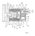
- FIG. 1 shows an electric motor according to a first preferred embodiment of the invention in sectional view.
- the electric motor shown in Fig. 1 is a brushless one DC motor realized, the invention being generally applicable to all electric motors is where the interior should be sealed from the outside and in particular to those that are designed as wet runners.
- a pump housing is generally designated 10.
- the pump housing 10 serves for receiving an impeller (not shown) and has an inlet and an outlet for the pumped medium. Since feed pumps are generally known in the prior art, the pump itself is not described here in further detail.
- the invention Electric motor is generally designated 20. It comprises a rotor 22, which has an iron yoke 24 and has a permanent magnet 26. At the two ends of the iron yoke 24 shaft stubs 28, 30 are connected to the iron yoke 24 in a rotationally fixed manner.
- the shaft ends 28, 30 are preferably hardened steel pins, but can also be made of any other suitable material.
- a continuous shaft (not shown) can be provided on which the iron yoke the rotor is mounted in the usual way.
- the electric motor 20 further includes a stator 32, a stator body 34 and phase windings 36 has.
- the stator body 34 can be constructed as a laminated laminated core his.
- the stator 32 is injected into a plastic material which has a plastic body 38 forms.
- the plastic body 38 forms a space for Recording of the stator 22, which is closed to a first end 40 (on the right in the figure).
- first end 40 on the right in the figure.
- second end 42 is that formed by the plastic body 38 Room open.
- a bearing seat 44 in the plastic body 38 formed, which receives a roller bearing 46, in particular a ball bearing.
- the roller bearing 46 is used to mount the rotor 22 in the plastic body 38.
- a slide bearing for example a, for mounting the rotor 22 hydrodynamic fluid bearing, formed between the stub shaft 30 and a sleeve 48, which is integrated into the stimulating end 40 of the plastic body 38.
- hydrodynamic fluid bearings are known in the prior art and described, for example in the U.S. Patent 4,934,8636. If other types of bearings are selected, so can the shaft is made of a different, softer material.
- a magnetic disk 50 is placed on the end of the rotor 22, which serves as a signal generator for detecting the position and speed of the rotor 22.
- the Magnet disk 50 is opposite, outside the plastic body 38, a sensor board 52 arranged which Hall elements or other sensors for detecting the rotational position and / or Speed of the rotor in connection with the magnetic disc 50 can carry.
- An electronic assembly is also outside the first end 40 of the plastic body 38 arranged, generally designated 54, which for controlling and supplying the Electric motor 20 is used.
- the electronics assembly 54 includes, for example, a buffer capacitor 56, a suppression choke 58, FET power transistors 60 and pins 62 for electrical connection of the motor phases in the form shown in the embodiment shown are made of metal tongues.
- the electronics assembly 54 further includes outside leading pins 64, 64 'for connecting the electric motor 20 to the positive and the negative connection of a power supply, one of the pins 64, as in 1 is connected directly to the interference suppression choke 38.
- the electronic assembly 54 is between the plastic body 38 and a cover 66 included, the cover 66 against the plastic body 38 via an O-ring 68 or another suitable seal is sealed.
- Another O-ring seal 70 is between the plastic body 38 and the pump housing 10 are provided.
- a carrier component 72 is used for the positionally accurate mounting of various components the electronics assembly, such as pins 64, 64 ', capacitors 56 and the like serves.
- the carrier component 72 is against the cover 66 with a further O-ring seal 74 sealed.
- the stator 32 is completely injected into the plastic body 38, the Plastic body is closed at the first end 40. It is preferably one-sided closed plastic body 38 produced in one injection molding process as a one-piece component.
- the plastic body 38 has the function of sealing the entire electromechanical Assembly against the pumped medium of the pump and the protection of the stator assembly 32 against all environmental influences from outside.
- the stator 32, with the stator body 34 and phase winding 36 preferably completely interconnected before it is overmolded, so that only the phase connections, for example three connections in a three-phase motor, however, the individual wires of the windings 36 are not led out of the plastic body 38 are.
- plastic body 38 further functions are preferably integrated in the plastic body 38, such as bearing seats and fasteners for connecting the plastic body 38 with the pump housing 10.
- the plastic body 38 can also be used for positioning and fixing serve the sensor board 52 and the electronics module 54 or parts thereof. It can also be provided in the plastic body 38, in particular on the outside, metal parts to integrate to shield the electric motor from the outside. Metal particles, a metal grid or the like when molding the plastic body 38 directly be injected with.
- the main function of the plastic body 38 is, however, the completely tight separation of the for the medium accessible space for receiving the rotor 22 of all electromechanical Components.
- the plastic body 38 takes over, in which the Stator is embedded, the function of the can and at the same time at least partially load-bearing function of a housing for positioning further components of the electric motor and for fastening the electric motor 20 to the pump housing 10.
- the plastic body protects the stator assembly against external environmental influences.
- the invention is applicable to both internal rotor motors and external rotor motors.
- the plastic body 38 could also do this Replace pump housing 10 or part of it by directing the impeller (not shown) connected to the rotor 22 and received in the plastic body 38.
- a housing for a pump wheel can be attached directly to the plastic body 38 molded or integrally formed with this.
- the iron yoke 24 of the rotor takes over 22 at least partially the function of a shaft, so that preferably hardened steel pins can be used as shaft ends 28, 30.
- Such hardened steel pins are special when forming one or both bearings as plain bearings, as at 48, appropriate. Hardened pins are commercially available as finished components. Alternatively, of course a continuous wave can also be used.
- the formation of the iron yoke 24 according to FIG. 1 has the further advantage that it is easier is to integrate ball bearings, such as the bearing 46, in the iron yoke 24.
- the iron yoke 24 can be designed with such an outer diameter, that the bearing size to be adapted to the inside diameter of the plastic body 38 can.
- the same function would require an extremely large diameter shaft is provided.
- the rotor 22 with the iron yoke 24 and the permanent magnet 26 is with a as smooth a surface as possible so that when the rotor rotates in the Plastic body 38 enclosed space as little or no turbulence of the To convey the medium.
- Fig. 2 shows a sectional view through an alternative embodiment of an electric motor according to the invention.
- the same or corresponding components as in FIG. 1 are identified by the same reference numerals and are not described again here.
- the Electronics assembly 54 and cover 66 are not shown in FIG. 2. You can like in Fig. 1 or be formed differently.
- FIG. 2 differs from FIG. 1 essentially in that the stator 32 is encapsulated by a plastic body 80, which on both ends 40, 42 is open. At the first end 40, the plastic body 80 is covered 82, which is preferably also made of plastic, closed. The cover 82 is with the plastic body 80 by means of screws 84 or by other connecting means tightly connected. The cover 82 is against the plastic body 38 via an O-ring 90 or some other suitable seal.
- the rotor 22 is on a shaft 86 via the Rolling bearings 46 and a further rolling bearing 88 are mounted in the plastic body 38.
- the motor shaft 86 with a pre-assembled rotor 20 and Bearings 46, 86 are pushed from the right into the plastic body 38 in the drawing is then closed with the cover 82.
- the cover 82 is fixed via the outer ring of the roller bearing 88, the shaft 86 in the axial direction.
- the cover 82 can be preassembled with a sensor board (not shown in FIG. 2), which Hall elements or other sensors for detecting the rotational position and rotational speed of the rotor 22. As in the embodiment of Fig. 1 is on the front side 40 of the rotor 22, a magnetic disk 50 is applied for this purpose, which commutation signals emits through the wall of the cover 82 to the sensor board.
- the roller bearing 46 in particular a ball bearing, is used for precise centering of the motor on the pump housing 10.
- This ball bearing 46 can both function the motor mounting as well as the pump storage.
- Fig. 3 shows an exploded perspective view of the invention 1.
- the same or corresponding components as in FIG. 1 are included the same reference numerals.
- the plastic body 38 one-sided forms a closed space for receiving the rotor 22, this space at the first End 40 is closed by a wall 92 which is shaped so that it the stub shaft 30 and the plain bearing sleeve 48 can accommodate.
- the sensor board 52 On the wall 92 is the sensor board 52 arranged, which carries connecting pins 94.
- the connecting pins 94 can be connected to a connector 96, which is the sensor system provided on the sensor board 52 connects with the other components of the electronics module 54.
- the electronics assembly 54 as shown essentially in FIG. 1, on a single board or in several levels, for example on two boards 98, 100. You can the transistors 60 are constructed and connected so that their connecting legs at least partially through upper board 100 and lower board 98 can be connected directly.
- With regard to the construction of the electronics module reference is made Taken on German patent application dated 28.08.2002 with the file number 102 39 512.8.
- connection pins 62 are immediate are connected to the phase windings 36 of the stator 32 via metal tongues 102 connected to the electronics module 54.
- the metal tongues 102 and the pins 62 after the assembly of the various components of the electric motor 20 brought to congruence and connected for example with a welding gun.
- the electronics assembly 54 or parts thereof could be arranged outside the electric motor.
- those on the sensor board 52 located sensors and the electronics module 54 can be summarized.
- a fully enclosed electric motor is provided in the invention, which contains the electronics necessary for the motor control, so that only supply connections in the form of the connecting pins 64, 64 'to the outside.
- the positive supply connection 64 directly with the interference suppression choke 58 connected, whereby a mechanically resilient mounting of the pin 64 is created, which facilitates the insertion of the pin 64 in the support member 72.
- the interference suppressor 54 thus has a mechanical function in addition to its electrical function Holding function that allows a certain mobility of the pin 64.
- the other, negative supply connection 64 ' can be connected via a cable piece 104 to one of the metal tongues 102 for connection to the phases 36 of the stator 32 are coupled. Both pins 64 and 64 'have openings 65, which with corresponding locking lugs (not shown) cooperate in the support member 72.
- FIG. 3 shows O-rings 106, 108 for sealing the Rolling bearing 46 against the plastic body 38 or the support member 72 against the cover 66. Also shown in FIG. 3 is a groove 110 on the second end face 42 of the plastic body 38, which serves to receive the O-ring 70.
- the components are the electronic assembly 54 connected via the metal tongues 102 and further metal rails, the are provided on or in the circuit board 100.
- These traces can be used as lead frames or be realized as individual connection components.
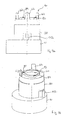
- FIGS. 4A and 4B show a side view and a perspective view of the plastic body 80, which is mounted on the pump housing 10.
- FIGS. 4A, 4B lead from the plastic body 80 only the pins 62 for the three phases of Phase windings 36 of the stator 32 out.
- the embodiment shown in Figs. 4A, 4B corresponds to the representation of FIG. 2, so that the plastic body 80 at the first end 40 is closed by the cover 82.
- the cover 82 is with the plastic body 80 connected by screws 84.
- the Plastic body 80 is designed with fastening means 112 in the manner of a flange to connect the plastic body 80 directly to the pump housing 10.
- 5A, 5B finally show an exploded view and a perspective view Overall representation of the rotor 22 of the electric motor of FIG. 1.
- the same or The same components as in Fig. 1 are denoted by the same reference numerals.
- the electric motor according to the invention is preferably used as a drive for a hydraulic steering aid used in motor vehicles, but it is basically suitable as a pump motor or, as a wet runner for various applications.
Landscapes
- Engineering & Computer Science (AREA)
- Power Engineering (AREA)
- Mechanical Engineering (AREA)
- General Engineering & Computer Science (AREA)
- Manufacturing & Machinery (AREA)
- Microelectronics & Electronic Packaging (AREA)
- Motor Or Generator Frames (AREA)
- Connection Of Motors, Electrical Generators, Mechanical Devices, And The Like (AREA)
- Structures Of Non-Positive Displacement Pumps (AREA)
- Insulation, Fastening Of Motor, Generator Windings (AREA)
Abstract
Description
- Fig. 1
- eine Schnittdarstellung durch eine erste Ausführungsform des erfindungsgemäßen Elektromotors;
- Fig. 2
- eine Schnittdarstellung durch eine zweite Ausführungsform des erfindungsgemäßen Elektromotors;
- Fig. 3
- eine auseinandergezogene perspektivisch Darstellung des erfindungsgemäßen Elektromotors gemäß der ersten Ausführungsform;
- Fig. 4A und 4B
- eine Seitenansicht bzw. eine perspektivische Ansicht des Kunststoffkörpers des erfindungsgemäßen Elektromotors;
- Fig. 5A und 5B
- eine auseinandergezogene Darstellung bzw. eine perspektivische Ansicht des Rotors des erfindungsgemäßen Elektromotors.
- 10
- Pumpengehäuse
- 20
- Elektromotor
- 22
- Rotor
- 24
- Eisenrückschluß
- 26
- Permanentmagnet
- 28, 30
- Wellenstummel
- 32
- Stator
- 34
- Statorkörper
- 36
- Phasenwicklungen
- 38
- Kunststoffkörper
- 40
- erstes Stirnende
- 42
- zweites Stirnende
- 44
- Lagersitz
- 46
- Wälzlager
- 48
- Gleitlager - Hülse
- 50
- Magnetscheibe
- 52
- Sensorplatine
- 54
- Elektronik-Baugruppe
- 56
- Pufferkondensator
- 58
- Entstördrossel
- 60
- FET-Leistungstransistor
- 62, 64, 64'
- Anschlußstifte
- 65
- Öffnung
- 66
- Deckel
- 68, 70
- O-Ring
- 72
- Trägerbauteil
- 74
- O-Ring
- 80
- Kunststoffkörper
- 82
- Abdeckung
- 84
- Schraube
- 86
- Welle
- 88
- Wälzlager
- 90
- O-Ring
- 92
- Wand
- 94
- Verbindungsstifte
- 96
- Stecker
- 98, 100
- Platinen
- 102
- Metallzungen
- 104
- Kabelstück
- 106, 108
- O-Ringe
- 110
- Nut
- 112
- Befestigungsmittel
Claims (13)
- Elektromotor für einen Pumpenantrieb mit einem Stator (32) und einem Rotor (22) zum Antreiben eines Pumpenrades, wobei der Stator in einen Kunststoffkörper (38; 80) eingebettet ist und der Kunststoffkörper (38; 80) zusammen mit dem Stator (32) einen Raum bildet, in dem der Rotor aufgenommen ist, wobei der Raum an einem ersten Stirnende (40) des Rotors (22) geschlossen ist und der Rotor (22) an seinem gegenüberliegenden zweiten Stimende (42) mit dem Pumpenrad verbunden ist.
- Elektromotor nach Anspruch 1, dadurch gekennzeichnet, daß der Kunststoffkörper (38; 80) durch Spritzgießen hergestellt ist.
- Elektromotor nach Anspruch 1 oder 2, dadurch gekennzeichnet, daß der Kunststoffkörper (38), der den Stator (32) umgibt, einen an dem ersten Stirnende (40) geschlossenen Raum bildet, der in einem Gießvorgang einteilig hergestellt ist.
- Elektromotor nach Anspruch 1 oder 2, dadurch gekennzeichnet, daß der Kunststoffkörper (80), der den Stator (32) umgibt, einen an beiden Stirnenden (40, 42) offenen Raum bildet, der bei dem ersten Stirnende (40) durch eine Abdeckung (82) verschlossen ist.
- Elektromotor nach einem der vorangehenden Ansprüche, dadurch gekennzeichnet, daß bei dem zweiten Stirnende (42) ein Lagersitz zur Aufnahme eines Wälzlagers (46) zur Lagerung des Rotors in eine Innenwand des Raumes integriert ist.
- Elektromotor nach einem der vorangehenden Ansprüche, dadurch gekennzeichnet, daß der Rotor (22) auf einer Welle (28, 30) sitzt, die bei dem ersten Stirnende (40) durch ein Gleitlager (48) gelagert ist.
- Elektromotor nach einem der vorangehenden Ansprüche, dadurch gekennzeichnet, daß der Rotor (22) einen Eisenrückschluß (24) aufweist, der an den beiden Stirnenden mit Wellenstummeln (28, 30) verbunden ist.
- Elektromotor nach einem der vorangehenden Ansprüche, dadurch gekennzeichnet, daß der Stator (32) einen Statorkern (34) und Phasen-Wicklungen (36) aufweist, welche mit jeweils einem Anschlußmittel (62) für jede Phase verbunden sind, wobei der Kunststoffkörper (38; 80) den bewickelten Stator (32) so umschließt, daß nur die Anschlußmittel (62) zugänglich sind.
- Elektromotor nach einem der vorangehenden Ansprüche, dadurch gekennzeichnet, daß der in dem Raum aufgenommene Rotor (22) bei Betrieb des Elektromotors in Verbindung mit einer Pumpe von einem Fördermedium umspült ist.
- Elektromotor nach einem der vorangehenden Ansprüche, gekennzeichnet durch eine Elektronik (54) zur Ansteuerung des Elektromotors (20), die außerhalb des Raumes angeordnet ist.
- Elektromotor nach Anspruch 9 und 10, dadurch gekennzeichnet, daß die Elektronik (54) durch den Kunststoffkörper (38; 80) von dem Fördermedium getrennt ist.
- Elektromotor nach Anspruch 8 und 10, dadurch gekennzeichnet, daß die Anschlußmittel (62) für jede Phase des Elektromotors eine Kontaktzunge aufweisen und die Elektronik (54) entsprechende Kontaktzungen (102) aufweist, welche neben den Kontaktzungen der Anschlußmittel (62) zu liegen kommen, um diese miteinander zu verbinden.
- Elektromotor nach einem der vorangehenden Ansprüche, dadurch gekennzeichnet, daß wenigstens in Teile des Kunststoffkörpers (38; 80) Metallteile integriert sind, um den Elektromotor (20) nach außen abzuschirmen.
Applications Claiming Priority (2)
| Application Number | Priority Date | Filing Date | Title |
|---|---|---|---|
| DE10254670A DE10254670A1 (de) | 2002-11-22 | 2002-11-22 | Elektromotor für einen Pumpenantrieb |
| DE10254670 | 2002-11-22 |
Publications (3)
| Publication Number | Publication Date |
|---|---|
| EP1422809A2 true EP1422809A2 (de) | 2004-05-26 |
| EP1422809A3 EP1422809A3 (de) | 2005-06-01 |
| EP1422809B1 EP1422809B1 (de) | 2006-12-13 |
Family
ID=32185915
Family Applications (1)
| Application Number | Title | Priority Date | Filing Date |
|---|---|---|---|
| EP03022875A Expired - Lifetime EP1422809B1 (de) | 2002-11-22 | 2003-10-08 | Elektromotor für einen Pumpenantrieb |
Country Status (4)
| Country | Link |
|---|---|
| US (1) | US20040108779A1 (de) |
| EP (1) | EP1422809B1 (de) |
| JP (1) | JP2004180495A (de) |
| DE (2) | DE10254670A1 (de) |
Cited By (7)
| Publication number | Priority date | Publication date | Assignee | Title |
|---|---|---|---|---|
| EP2302220A3 (de) * | 2007-01-18 | 2012-04-11 | Grundfos Management A/S | Pumpenaggregat |
| WO2014079611A3 (de) * | 2012-11-26 | 2015-03-19 | Robert Bosch Gmbh | Stator mit einer umspritzung und elektrische maschine mit dem stator |
| WO2018162620A1 (de) * | 2017-03-10 | 2018-09-13 | Kolektor Group D.O.O. | Elektromotor |
| WO2019091763A1 (de) * | 2017-11-13 | 2019-05-16 | Magna Powertrain Bad Homburg GmbH | Wasserpumpe und verfahren zur herstellung einer wasserpumpe |
| EP3476028A4 (de) * | 2016-06-27 | 2020-08-05 | ABB Schweiz AG | Elektrische maschine |
| WO2020169821A1 (de) * | 2019-02-22 | 2020-08-27 | Metabowerke Gmbh | Grundkörper für einen elektromotor |
| WO2023186297A1 (de) | 2022-03-30 | 2023-10-05 | Pierburg Gmbh | Elektrische maschine |
Families Citing this family (48)
| Publication number | Priority date | Publication date | Assignee | Title |
|---|---|---|---|---|
| DE602004023556D1 (de) * | 2003-05-28 | 2009-11-26 | Aisin Seiki | Elektrisch angetriebene Pumpe |
| JP4428632B2 (ja) * | 2004-03-10 | 2010-03-10 | 株式会社小糸製作所 | アクチュエータ |
| DE102004042271A1 (de) * | 2004-09-01 | 2006-03-02 | Robert Bosch Gmbh | Vorrichtung zur Aufnahme eines Elektromotors |
| DE102004050373A1 (de) | 2004-10-15 | 2006-04-27 | Minebea Co., Ltd. | Statoranordnung für eine elektrische Maschine und Elektromotor |
| DE102005046284A1 (de) * | 2005-02-28 | 2006-08-31 | Temic Automotive Electric Motors Gmbh | Elektromotor |
| PL1719916T3 (pl) * | 2005-05-07 | 2009-01-30 | Grundfos Management As | Agregat pompowy |
| DE102005039557A1 (de) * | 2005-08-22 | 2007-03-01 | Robert Bosch Gmbh | Kreiselpumpe |
| US20070152523A1 (en) * | 2005-12-12 | 2007-07-05 | Franklin Electric Co., Inc. | Submersible Motor with molded encapsulated stator |
| TWI363141B (en) * | 2006-01-11 | 2012-05-01 | Delta Electronics Inc | Water pump and bearing thereof |
| EP1918567A1 (de) * | 2006-10-27 | 2008-05-07 | Delphi Technologies, Inc. | Kraftstofffördermodul |
| JPWO2008136061A1 (ja) * | 2007-04-19 | 2010-07-29 | 三菱電機株式会社 | 電動機及びポンプ及び電動機の製造方法 |
| DE102008014379A1 (de) * | 2008-03-17 | 2009-09-24 | Sycotec Gmbh & Co. Kg | Elektromechanische Maschine |
| JP5378009B2 (ja) * | 2009-03-04 | 2013-12-25 | 山洋電気株式会社 | 電動送風機 |
| KR101117553B1 (ko) * | 2009-08-17 | 2012-03-07 | 주식회사 아모텍 | 방수구조를 갖는 워터펌프 모터 및 이를 이용한 워터펌프 |
| JP5522009B2 (ja) * | 2010-12-02 | 2014-06-18 | 株式会社豊田自動織機 | 電動圧縮機 |
| JP5382036B2 (ja) * | 2011-03-16 | 2014-01-08 | 株式会社豊田自動織機 | 電動圧縮機 |
| KR101337835B1 (ko) * | 2012-01-30 | 2013-12-06 | 주식회사 티엠테크아이 | 개방된 자석 구조의 습식 모터를 갖는 조향 펌프 |
| PT2672007E (pt) | 2012-06-04 | 2015-11-26 | Vossloh Werke Gmbh | Placa de guia para a fixação de carris para veículos ferroviários |
| KR101316144B1 (ko) * | 2012-06-11 | 2013-10-08 | 뉴모텍(주) | 모터 |
| US9041259B2 (en) * | 2012-07-18 | 2015-05-26 | Delphi Technologies, Inc. | Actuator assembly having a motor with heat dissipation |
| DE202012013649U1 (de) * | 2012-07-20 | 2018-12-02 | Ebm-Papst Mulfingen Gmbh & Co. Kg | Elektronikgehäuse für einen Elektromotor mit Berührungsschutz |
| DE102012222358A1 (de) * | 2012-12-05 | 2014-06-05 | Mahle International Gmbh | Elektrische Flüssigkeitspumpe |
| DE102014219219A1 (de) * | 2014-09-24 | 2016-03-24 | Robert Bosch Gmbh | Förderaggregat |
| DE102015203775A1 (de) * | 2015-03-03 | 2016-09-08 | Robert Bosch Gmbh | Antriebseinrichtung, insbesondere als Bestandteil eines Komfortantrieb in einem Kraftfahrzeug |
| GB201507256D0 (en) * | 2015-04-28 | 2015-06-10 | Coreteq Ltd | Stator |
| JP6590535B2 (ja) * | 2015-05-29 | 2019-10-16 | 日本電産トーソク株式会社 | ポンプ装置 |
| DE102016204968A1 (de) * | 2016-03-24 | 2017-09-28 | Robert Bosch Gmbh | Elektrische Maschine sowie Verfahren zum Herstellen einer elektrischen Maschine |
| JP6406310B2 (ja) * | 2016-04-28 | 2018-10-17 | マツダ株式会社 | 電動モータ構造及び電動モータの製造方法 |
| SG11201809524RA (en) * | 2016-04-29 | 2018-11-29 | Fisher & Paykel Healthcare Ltd | Blower for breathing apparatus |
| EP3242032B1 (de) * | 2016-05-04 | 2019-11-06 | Grundfos Holding A/S | Spaltrohrpumpe wobei sowohl der motorstator als auch das elektronikmodul vergossen sind |
| DE102016114540A1 (de) | 2016-08-05 | 2018-02-08 | Eckerle Industrie-Elektronik Gmbh | Elektrohydraulische Maschine mit integriertem Sensor |
| FR3060064A1 (fr) * | 2016-12-08 | 2018-06-15 | Valeo Japan Co., Ltd. | Compresseur pour une installation de conditionnement d'air d'un vehicule automobile muni d'un couvercle a etancheite amelioree |
| DE202017100708U1 (de) * | 2017-02-09 | 2017-05-03 | Johnson Electric Germany GmbH & Co. KG | Linearschrittmotor mit einer Rotorspindel für einen linear geführten Stellantrieb |
| US10574114B2 (en) * | 2017-05-02 | 2020-02-25 | Moog Inc. | Electric motor for use in pressurized fluid environment |
| DE102017209519B4 (de) * | 2017-06-07 | 2024-03-28 | Vitesco Technologies Germany Gmbh | Elektronisches Bauteil und Verfahren zu dessen Herstellung |
| DE102017209896A1 (de) * | 2017-06-12 | 2018-12-13 | Magna Powertrain Bad Homburg GmbH | Elektrische Maschinen mit Verschaltring sowie Verfahren zur Montage einer solchen |
| US10677514B2 (en) | 2017-08-01 | 2020-06-09 | Whirlpool Corporation | Door bin with dual material and system lock |
| EP3490115A1 (de) * | 2017-11-28 | 2019-05-29 | Siemens Aktiengesellschaft | Integrierter klemmenkasten einer rotatorischen dynamoelektrischen maschine |
| EP4336713A3 (de) | 2018-07-19 | 2024-06-05 | Agilent Technologies, Inc. | Vakuumpumpsystem mit ölgeschmierter vakuumpumpe |
| JP7068979B2 (ja) * | 2018-09-21 | 2022-05-17 | Ntn株式会社 | 電動アクチュエータ |
| JP2021057996A (ja) * | 2019-09-30 | 2021-04-08 | 日本電産株式会社 | モータユニット |
| US20240113573A1 (en) * | 2020-12-10 | 2024-04-04 | Pierburg Pump Technology Gmbh | Automotive electric auxiliary unit and method for manufacturing the same |
| DE102021123150A1 (de) | 2021-09-07 | 2023-03-09 | Nidec Corporation | Elektromotor mit einer in das Lagerschild integrierten magnetischen Abschirmung |
| JP7743333B2 (ja) * | 2022-02-22 | 2025-09-24 | サンデン株式会社 | 電動圧縮機 |
| DE102023104758A1 (de) * | 2022-03-18 | 2023-09-21 | Makita Corporation | Elektroarbeitsmaschine |
| CN115143126A (zh) * | 2022-07-29 | 2022-10-04 | 四川芯智热控技术有限公司 | 一种具有包塑结构的电子水泵 |
| DE102023207408A1 (de) * | 2023-08-02 | 2025-02-06 | Vitesco Technologies GmbH | Fluidpumpe, Kraftfahrzeug, Herstellverfahren für eine solche Fluidpumpe und Verwendung einer solchen Fluidpumpe in einem Wärmetransportmittelkreis(lauf) |
| CN118188513A (zh) * | 2024-03-22 | 2024-06-14 | 马勒汽车技术(苏州)有限公司 | 电子水泵 |
Family Cites Families (32)
| Publication number | Priority date | Publication date | Assignee | Title |
|---|---|---|---|---|
| US363473A (en) * | 1887-05-24 | Holdback | ||
| GB987265A (en) * | 1962-02-22 | 1965-03-24 | Sigmund Pumps Ltd | A pump and electric motor unit for pumping liquids |
| GB966156A (en) * | 1962-07-03 | 1964-08-06 | English Electric Co Ltd | Dynamo-electric machines |
| US3163369A (en) * | 1962-07-13 | 1964-12-29 | Gen Electric | Encapsulated motor for waste disposal apparatus |
| GB979009A (en) * | 1962-10-18 | 1965-01-01 | Hevent Developments Ltd | Improvements in or relating to glandless motor driven circulating pumps |
| US3333544A (en) * | 1965-03-22 | 1967-08-01 | Vincent K Smith | Water pump motor constructions |
| US3859548A (en) * | 1973-05-18 | 1975-01-07 | Amf Inc | Permanent magnet motor |
| US3873861A (en) * | 1973-06-15 | 1975-03-25 | Richard Halm | Electric motor, especially a squirrel-cage motor |
| DE2739125A1 (de) * | 1977-08-31 | 1979-03-15 | Hanning Elektro Werke | Elektrisch betriebener oelbrennermotor |
| JPS60170437A (ja) * | 1984-02-10 | 1985-09-03 | Mitsubishi Electric Corp | キヤンドモ−トルおよびその製造方法 |
| DK149716C (da) * | 1984-02-29 | 1987-05-25 | Smedegaard As | Hus til en spaltroer-motor-pumpe og fremgangsmaade til fremstilling heraf |
| US4934836A (en) * | 1988-08-18 | 1990-06-19 | Nippon Seiko Kabushiki Kaisha | Dynamic pressure type fluid bearing device |
| DE8811420U1 (de) * | 1988-09-09 | 1989-01-19 | Halm, Richard, 7066 Baltmannsweiler | Naßläufermotor |
| DE3833574A1 (de) * | 1988-10-03 | 1990-04-05 | Grundfos Int | Elektromotor, insbesondere spaltrohrmotor |
| WO1993008632A1 (en) * | 1991-10-25 | 1993-04-29 | Filmlab Engineering Pty Limited | A magnetically coupled motor |
| US5714814A (en) * | 1993-11-29 | 1998-02-03 | Askoll S.P.A. | Support for the rotor shaft of a centrifugal pump with permanent-magnet electric motor |
| DE29505575U1 (de) * | 1994-05-04 | 1995-06-14 | Halm, Richard, 73666 Baltmannsweiler | Naßläufer-Spaltrohrmotor für Pumpen |
| US5872414A (en) * | 1995-02-07 | 1999-02-16 | Sawafuji Electric Co., Ltd | Electric rotating machine |
| DE19623460A1 (de) * | 1996-06-12 | 1997-12-18 | Siemens Ag | Elektrische Maschine |
| DE19705974A1 (de) * | 1997-02-17 | 1998-08-20 | Wilo Gmbh | Elektromotor für eine Pumpe oder einen Lüfter |
| US6065946A (en) * | 1997-07-03 | 2000-05-23 | Servo Magnetics, Inc. | Integrated controller pump |
| DE19752884A1 (de) * | 1997-11-28 | 1999-06-10 | Bosch Gmbh Robert | Förderaggregat für Kraftstoff |
| DE19824345A1 (de) * | 1998-06-02 | 1999-12-09 | Wilo Gmbh | Spaltrohrpumpe mit Wicklungsträger |
| DE19903817A1 (de) * | 1999-02-02 | 2000-08-10 | Bosch Gmbh Robert | Kühlwasserpumpe |
| JP3881126B2 (ja) * | 1999-03-05 | 2007-02-14 | アスモ株式会社 | モータ |
| DE19956380C1 (de) * | 1999-11-24 | 2001-01-04 | Bosch Gmbh Robert | Flüssigkeitspumpe mit einem Motorgehäuse und Verfahren zur Herstellung eines Motorgehäuses |
| DE19964061A1 (de) * | 1999-12-30 | 2001-07-05 | Bosch Gmbh Robert | Elektromotor, insbesondere für Handwerkzeugmaschinen |
| DE10043235A1 (de) * | 2000-09-02 | 2002-03-14 | Leybold Vakuum Gmbh | Vakuumpumpe |
| DE10045596B4 (de) * | 2000-09-15 | 2004-07-01 | Bühler Motor GmbH | Pumpe mit einem elektronisch kommutierten Gleichstrommotor |
| DE10052797A1 (de) * | 2000-10-25 | 2002-05-08 | Bosch Gmbh Robert | Elektromotorisch angetriebene Pumpe und Verfahren zur Herstellung einer solchen Pumpe |
| DE10103209A1 (de) * | 2001-01-24 | 2002-07-25 | Wilo Gmbh | Motorgehäuse mit Spalttopf |
| JP3593102B2 (ja) * | 2002-01-08 | 2004-11-24 | 三菱電機株式会社 | 電動パワーステアリング装置 |
-
2002
- 2002-11-22 DE DE10254670A patent/DE10254670A1/de not_active Ceased
-
2003
- 2003-10-08 DE DE50305945T patent/DE50305945D1/de not_active Expired - Lifetime
- 2003-10-08 EP EP03022875A patent/EP1422809B1/de not_active Expired - Lifetime
- 2003-10-20 US US10/687,834 patent/US20040108779A1/en not_active Abandoned
- 2003-11-13 JP JP2003383481A patent/JP2004180495A/ja active Pending
Cited By (18)
| Publication number | Priority date | Publication date | Assignee | Title |
|---|---|---|---|---|
| EP2302219A3 (de) * | 2007-01-18 | 2012-04-11 | Grundfos Management A/S | Pumpenaggregat |
| EP2302218A3 (de) * | 2007-01-18 | 2012-04-11 | Grundfos Management A/S | Pumpenaggregat |
| EP2860403A1 (de) * | 2007-01-18 | 2015-04-15 | Grundfos Management A/S | Pumpenaggregat |
| EP2302220A3 (de) * | 2007-01-18 | 2012-04-11 | Grundfos Management A/S | Pumpenaggregat |
| WO2014079611A3 (de) * | 2012-11-26 | 2015-03-19 | Robert Bosch Gmbh | Stator mit einer umspritzung und elektrische maschine mit dem stator |
| EP3476028A4 (de) * | 2016-06-27 | 2020-08-05 | ABB Schweiz AG | Elektrische maschine |
| US11277050B2 (en) | 2017-03-10 | 2022-03-15 | Kolektor Group D.O.O. | Electric motor |
| WO2018162620A1 (de) * | 2017-03-10 | 2018-09-13 | Kolektor Group D.O.O. | Elektromotor |
| KR20200071111A (ko) * | 2017-11-13 | 2020-06-18 | 한온 시스템즈 이에프피 도이칠란드 게엠베하 | 물 펌프 및 물 펌프 제조 방법 |
| CN111315995A (zh) * | 2017-11-13 | 2020-06-19 | 翰昂汽车零部件德国有限公司 | 水泵和用于制造水泵的方法 |
| WO2019091763A1 (de) * | 2017-11-13 | 2019-05-16 | Magna Powertrain Bad Homburg GmbH | Wasserpumpe und verfahren zur herstellung einer wasserpumpe |
| US11371519B2 (en) | 2017-11-13 | 2022-06-28 | Hanon Systems Efp Deutschland Gmbh | Water pump and method for manufacturing a water pump |
| DE102017220157B4 (de) | 2017-11-13 | 2025-02-06 | Hanon Systems Efp Deutschland Gmbh | Wasserpumpe und Verfahren zur Herstellung einer Wasserpumpe |
| WO2020169821A1 (de) * | 2019-02-22 | 2020-08-27 | Metabowerke Gmbh | Grundkörper für einen elektromotor |
| CN113454887A (zh) * | 2019-02-22 | 2021-09-28 | 麦太保有限公司 | 用于电动机的基本体 |
| CN113454887B (zh) * | 2019-02-22 | 2024-08-13 | 麦太保有限公司 | 用于电动机的基本体 |
| US12074499B2 (en) | 2019-02-22 | 2024-08-27 | Metabowerke Gmbh | Basic body for an electric motor |
| WO2023186297A1 (de) | 2022-03-30 | 2023-10-05 | Pierburg Gmbh | Elektrische maschine |
Also Published As
| Publication number | Publication date |
|---|---|
| DE50305945D1 (de) | 2007-01-25 |
| US20040108779A1 (en) | 2004-06-10 |
| EP1422809A3 (de) | 2005-06-01 |
| DE10254670A1 (de) | 2004-06-24 |
| JP2004180495A (ja) | 2004-06-24 |
| EP1422809B1 (de) | 2006-12-13 |
Similar Documents
| Publication | Publication Date | Title |
|---|---|---|
| EP1422809B1 (de) | Elektromotor für einen Pumpenantrieb | |
| EP3411940B1 (de) | Elektromotor für eine fluidpumpe, modulare motorfamilie zur bildung unterschiedlicher fluidpumpen mit mehreren solcher elektromotoren und herstellungsverfahren | |
| DE102015214465A1 (de) | Ansteuervorrichtung und die ansteuervorrichtung aufweisende elektrische servolenkungsvorrichtung | |
| DE102012109863A1 (de) | Bürstenloser Motor | |
| DE102015214474A1 (de) | Ansteuereinheit und die ansteuereinheit aufweisende elektrische servolenkungsvorrichtung | |
| DE69200028T2 (de) | Hydraulische Bremsvorrichtung. | |
| EP1263119A2 (de) | Antriebsvorrichtung | |
| DE10051403A1 (de) | Rotorbaugruppe für einen Elektromotor und Innenläufer-Elektromotor | |
| DE102010041744A1 (de) | Lenkgetriebe mit Elektromotor, Steuereinheit und Sensorik sowie damit ausgestattetes elektrisches Hilfskraftlenksystem | |
| EP0623207B1 (de) | Sensor | |
| DE102006032780A1 (de) | Elektromotorischer Antrieb mit einem rotorseitig angeordneten Drehgeber | |
| WO2003026104A2 (de) | Antriebseinheit mit einem elektromotor für verstelleinrichtungen in kraftfahrzeugen | |
| DE102004059181A1 (de) | Maschine mit integriertem Drehgeber | |
| DE19523789C2 (de) | Bürstenloser Elektromotor | |
| DE10355076B4 (de) | Elektromotor mit Sensor zur Erfassung der Rotorlage | |
| EP1322026A1 (de) | Stator eines Elektromotors | |
| DE102015210788A1 (de) | Lagerschildsystem und elektromotorischer Antrieb mit einem Lagerschildsystem | |
| DE10130139C1 (de) | Flansch für einen Elektromotor, insbesondere für einen elektronisch kommutierten Gleichstrommotor | |
| EP3391509B1 (de) | Elektromotor | |
| EP1870199B1 (de) | Mehrachsendrehkopf für eine Werkzeugmaschine | |
| DE9415078U1 (de) | Feuchtigkeitsdicht geschlossenes Motor-Pumpen-Aggregat, insbesondere für eine Kraftfahrzeug-Antiblockier-Bremsvorrichtung | |
| DE102006059135A1 (de) | Elektrische Maschine | |
| EP0982483A2 (de) | Antriebseinrichtung | |
| DE10236702B3 (de) | Gleichstrommotor | |
| EP1662637A2 (de) | Elektrische Maschine, insbesondere bürstenloser Gleichstrommotor, und Verfahren zum Justieren einer Sensoreinheit in einer elektrischen Maschine |
Legal Events
| Date | Code | Title | Description |
|---|---|---|---|
| PUAI | Public reference made under article 153(3) epc to a published international application that has entered the european phase |
Free format text: ORIGINAL CODE: 0009012 |
|
| AK | Designated contracting states |
Kind code of ref document: A2 Designated state(s): AT BE BG CH CY CZ DE DK EE ES FI FR GB GR HU IE IT LI LU MC NL PT RO SE SI SK TR |
|
| AX | Request for extension of the european patent |
Extension state: AL LT LV MK |
|
| PUAL | Search report despatched |
Free format text: ORIGINAL CODE: 0009013 |
|
| AK | Designated contracting states |
Kind code of ref document: A3 Designated state(s): AT BE BG CH CY CZ DE DK EE ES FI FR GB GR HU IE IT LI LU MC NL PT RO SE SI SK TR |
|
| AX | Request for extension of the european patent |
Extension state: AL LT LV MK |
|
| 17P | Request for examination filed |
Effective date: 20050622 |
|
| AKX | Designation fees paid |
Designated state(s): DE FR IT SI |
|
| RBV | Designated contracting states (corrected) |
Designated state(s): DE FR IT SK |
|
| GRAP | Despatch of communication of intention to grant a patent |
Free format text: ORIGINAL CODE: EPIDOSNIGR1 |
|
| GRAS | Grant fee paid |
Free format text: ORIGINAL CODE: EPIDOSNIGR3 |
|
| GRAA | (expected) grant |
Free format text: ORIGINAL CODE: 0009210 |
|
| AK | Designated contracting states |
Kind code of ref document: B1 Designated state(s): DE FR IT SK |
|
| PG25 | Lapsed in a contracting state [announced via postgrant information from national office to epo] |
Ref country code: IT Free format text: LAPSE BECAUSE OF FAILURE TO SUBMIT A TRANSLATION OF THE DESCRIPTION OR TO PAY THE FEE WITHIN THE PRESCRIBED TIME-LIMIT;WARNING: LAPSES OF ITALIAN PATENTS WITH EFFECTIVE DATE BEFORE 2007 MAY HAVE OCCURRED AT ANY TIME BEFORE 2007. THE CORRECT EFFECTIVE DATE MAY BE DIFFERENT FROM THE ONE RECORDED. Effective date: 20061213 Ref country code: SK Free format text: LAPSE BECAUSE OF FAILURE TO SUBMIT A TRANSLATION OF THE DESCRIPTION OR TO PAY THE FEE WITHIN THE PRESCRIBED TIME-LIMIT Effective date: 20061213 |
|
| REF | Corresponds to: |
Ref document number: 50305945 Country of ref document: DE Date of ref document: 20070125 Kind code of ref document: P |
|
| EN | Fr: translation not filed | ||
| PLBE | No opposition filed within time limit |
Free format text: ORIGINAL CODE: 0009261 |
|
| STAA | Information on the status of an ep patent application or granted ep patent |
Free format text: STATUS: NO OPPOSITION FILED WITHIN TIME LIMIT |
|
| 26N | No opposition filed |
Effective date: 20070914 |
|
| PG25 | Lapsed in a contracting state [announced via postgrant information from national office to epo] |
Ref country code: FR Free format text: LAPSE BECAUSE OF FAILURE TO SUBMIT A TRANSLATION OF THE DESCRIPTION OR TO PAY THE FEE WITHIN THE PRESCRIBED TIME-LIMIT Effective date: 20070803 |
|
| PG25 | Lapsed in a contracting state [announced via postgrant information from national office to epo] |
Ref country code: FR Free format text: LAPSE BECAUSE OF FAILURE TO SUBMIT A TRANSLATION OF THE DESCRIPTION OR TO PAY THE FEE WITHIN THE PRESCRIBED TIME-LIMIT Effective date: 20061213 |
|
| REG | Reference to a national code |
Ref country code: DE Ref legal event code: R082 Ref document number: 50305945 Country of ref document: DE Representative=s name: BOEHMERT & BOEHMERT ANWALTSPARTNERSCHAFT MBB -, DE Ref country code: DE Ref legal event code: R081 Ref document number: 50305945 Country of ref document: DE Owner name: MINEBEA MITSUMI INC., JP Free format text: FORMER OWNER: MINEBEA CO., LTD., NAGANO, JP |
|
| PGFP | Annual fee paid to national office [announced via postgrant information from national office to epo] |
Ref country code: DE Payment date: 20221031 Year of fee payment: 20 |
|
| REG | Reference to a national code |
Ref country code: DE Ref legal event code: R071 Ref document number: 50305945 Country of ref document: DE |