EP1405754A2 - Steuervorrichtung und -verfahren für Automatikgetriebe - Google Patents
Steuervorrichtung und -verfahren für Automatikgetriebe Download PDFInfo
- Publication number
- EP1405754A2 EP1405754A2 EP20030022270 EP03022270A EP1405754A2 EP 1405754 A2 EP1405754 A2 EP 1405754A2 EP 20030022270 EP20030022270 EP 20030022270 EP 03022270 A EP03022270 A EP 03022270A EP 1405754 A2 EP1405754 A2 EP 1405754A2
- Authority
- EP
- European Patent Office
- Prior art keywords
- torque
- control
- automatic transmission
- point
- restore
- Prior art date
- Legal status (The legal status is an assumption and is not a legal conclusion. Google has not performed a legal analysis and makes no representation as to the accuracy of the status listed.)
- Withdrawn
Links
Images

Classifications
-
- F—MECHANICAL ENGINEERING; LIGHTING; HEATING; WEAPONS; BLASTING
- F02—COMBUSTION ENGINES; HOT-GAS OR COMBUSTION-PRODUCT ENGINE PLANTS
- F02D—CONTROLLING COMBUSTION ENGINES
- F02D41/00—Electrical control of supply of combustible mixture or its constituents
- F02D41/02—Circuit arrangements for generating control signals
- F02D41/021—Introducing corrections for particular conditions exterior to the engine
- F02D41/0215—Introducing corrections for particular conditions exterior to the engine in relation with elements of the transmission
- F02D41/023—Introducing corrections for particular conditions exterior to the engine in relation with elements of the transmission in relation with the gear ratio shifting
-
- B—PERFORMING OPERATIONS; TRANSPORTING
- B60—VEHICLES IN GENERAL
- B60W—CONJOINT CONTROL OF VEHICLE SUB-UNITS OF DIFFERENT TYPE OR DIFFERENT FUNCTION; CONTROL SYSTEMS SPECIALLY ADAPTED FOR HYBRID VEHICLES; ROAD VEHICLE DRIVE CONTROL SYSTEMS FOR PURPOSES NOT RELATED TO THE CONTROL OF A PARTICULAR SUB-UNIT
- B60W10/00—Conjoint control of vehicle sub-units of different type or different function
- B60W10/04—Conjoint control of vehicle sub-units of different type or different function including control of propulsion units
- B60W10/06—Conjoint control of vehicle sub-units of different type or different function including control of propulsion units including control of combustion engines
-
- B—PERFORMING OPERATIONS; TRANSPORTING
- B60—VEHICLES IN GENERAL
- B60W—CONJOINT CONTROL OF VEHICLE SUB-UNITS OF DIFFERENT TYPE OR DIFFERENT FUNCTION; CONTROL SYSTEMS SPECIALLY ADAPTED FOR HYBRID VEHICLES; ROAD VEHICLE DRIVE CONTROL SYSTEMS FOR PURPOSES NOT RELATED TO THE CONTROL OF A PARTICULAR SUB-UNIT
- B60W10/00—Conjoint control of vehicle sub-units of different type or different function
- B60W10/10—Conjoint control of vehicle sub-units of different type or different function including control of change-speed gearings
- B60W10/11—Stepped gearings
- B60W10/115—Stepped gearings with planetary gears
-
- B—PERFORMING OPERATIONS; TRANSPORTING
- B60—VEHICLES IN GENERAL
- B60W—CONJOINT CONTROL OF VEHICLE SUB-UNITS OF DIFFERENT TYPE OR DIFFERENT FUNCTION; CONTROL SYSTEMS SPECIALLY ADAPTED FOR HYBRID VEHICLES; ROAD VEHICLE DRIVE CONTROL SYSTEMS FOR PURPOSES NOT RELATED TO THE CONTROL OF A PARTICULAR SUB-UNIT
- B60W30/00—Purposes of road vehicle drive control systems not related to the control of a particular sub-unit, e.g. of systems using conjoint control of vehicle sub-units
- B60W30/18—Propelling the vehicle
- B60W30/19—Improvement of gear change, e.g. by synchronisation or smoothing gear shift
-
- F—MECHANICAL ENGINEERING; LIGHTING; HEATING; WEAPONS; BLASTING
- F02—COMBUSTION ENGINES; HOT-GAS OR COMBUSTION-PRODUCT ENGINE PLANTS
- F02D—CONTROLLING COMBUSTION ENGINES
- F02D41/00—Electrical control of supply of combustible mixture or its constituents
- F02D41/02—Circuit arrangements for generating control signals
- F02D41/021—Introducing corrections for particular conditions exterior to the engine
- F02D41/0215—Introducing corrections for particular conditions exterior to the engine in relation with elements of the transmission
-
- F—MECHANICAL ENGINEERING; LIGHTING; HEATING; WEAPONS; BLASTING
- F02—COMBUSTION ENGINES; HOT-GAS OR COMBUSTION-PRODUCT ENGINE PLANTS
- F02D—CONTROLLING COMBUSTION ENGINES
- F02D41/00—Electrical control of supply of combustible mixture or its constituents
- F02D41/02—Circuit arrangements for generating control signals
- F02D41/14—Introducing closed-loop corrections
- F02D41/1401—Introducing closed-loop corrections characterised by the control or regulation method
- F02D2041/1433—Introducing closed-loop corrections characterised by the control or regulation method using a model or simulation of the system
-
- F—MECHANICAL ENGINEERING; LIGHTING; HEATING; WEAPONS; BLASTING
- F02—COMBUSTION ENGINES; HOT-GAS OR COMBUSTION-PRODUCT ENGINE PLANTS
- F02D—CONTROLLING COMBUSTION ENGINES
- F02D2250/00—Engine control related to specific problems or objectives
- F02D2250/18—Control of the engine output torque
- F02D2250/21—Control of the engine output torque during a transition between engine operation modes or states
-
- F—MECHANICAL ENGINEERING; LIGHTING; HEATING; WEAPONS; BLASTING
- F16—ENGINEERING ELEMENTS AND UNITS; GENERAL MEASURES FOR PRODUCING AND MAINTAINING EFFECTIVE FUNCTIONING OF MACHINES OR INSTALLATIONS; THERMAL INSULATION IN GENERAL
- F16H—GEARING
- F16H2306/00—Shifting
- F16H2306/40—Shifting activities
- F16H2306/42—Changing the input torque to the transmission
-
- F—MECHANICAL ENGINEERING; LIGHTING; HEATING; WEAPONS; BLASTING
- F16—ENGINEERING ELEMENTS AND UNITS; GENERAL MEASURES FOR PRODUCING AND MAINTAINING EFFECTIVE FUNCTIONING OF MACHINES OR INSTALLATIONS; THERMAL INSULATION IN GENERAL
- F16H—GEARING
- F16H63/00—Control outputs from the control unit to change-speed- or reversing-gearings for conveying rotary motion or to other devices than the final output mechanism
- F16H63/40—Control outputs from the control unit to change-speed- or reversing-gearings for conveying rotary motion or to other devices than the final output mechanism comprising signals other than signals for actuating the final output mechanisms
- F16H63/50—Signals to an engine or motor
- F16H63/502—Signals to an engine or motor for smoothing gear shifts
Definitions
- This invention relates to a control apparatus and method for an automatic transmission mounted in an automobile or the like. More specifically, this invention relates to a method for determining timing to start torque-restore control.
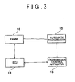
- FIG. 3 is a block diagram showing the arrangement of apparatuses and their general relationships with respect to control of a typical engine and automatic transmission. Because this drawing has also been applied to a related example, it will be used to describe control of an engine 10 and an automatic transmission 12 in a vehicle, which is disclosed in JPA 2-308934.
- An ECU (electronic control unit) 14 controls the operation of various valves and plugs and the like in the engine 10 while monitoring the rpm and the like of the engine 10 using various sensors provided therein.
- a transmission control apparatus 16 controls a clutch and the like provided in the automatic transmission while monitoring the rotational speed and the like of an input shaft from the engine 10 to the automatic transmission 12 using various sensors provided in the automatic transmission 12. Further, the ECU 14 and the transmission control apparatus 16 work in coordination to execute typical torque-down control during shifting and torque-restore control following that shift.
- Torque-down control in this case is control which is executed during a shift to reduce shift shock and extend the life of frictional engagement elements.
- This control temporarily reduces the torque output by the engine 10, i.e., engine torque, by a predetermined amount.
- the automatic transmission moves into an inertia phase and the rotational speed of the input shaft of the automatic transmission 12 gradually slows and approaches the speed that it needs to be for synchronization when the shift ends, i.e., approaches a shift-end synchronous speed.
- a predetermined target time i.e., a target inertia phase time
- JPA2-308934 estimates and detects a degree of change in the shift based on the difference between the current speed of rotating members inside the automatic transmission and the speed of those members at the end of the shift, and, based on those results, adaptively adjusts the amount of change of the engine torque in the torque-restore control. Detection of the degree of change in the shift is done using a map created with consideration given to various numerical values and quantities of state, such as the engine throttle opening amount, engine speed, and gear speed of the automatic transmission. Creating this map requires a tremendous number of man-hours.
- this invention thus provides a control apparatus which focuses on the behavior of an automatic transmission over time and obviates the need to both detect the degree of change in the shift and create a map and the like beforehand for that detection, and can therefore be realized at a lower cost than the related art.
- a control apparatus of the invention controls a torque of an engine coupled to an input shaft of an automatic transmission during a shift by the automatic transmission, includes torque-down controlling means for performing torque-down control by which the engine torque is decreased by a predetermined amount, torque-restore control starting point determining means for determining, during the torque-down control, a torque-restore control starting point at which time torque-restore control is to be started, and torque restoring means for starting the torque-restore control at the torque-restore control starting point so as to gradually restore the engine torque to a value before the torque-down control was performed.
- This control apparatus is characterised in that the torque-restore control starting point determining means determines the torque-restore control starting point according to a dynamic model which simulates the behavior of the automatic transmission over time from the start of the torque-down control, and so that a rotational speed of the input shaft of the automatic transmission at a target point (i.e., at a point at which a target inertia phase time has elapsed from the start of the inertia phase) comes to substantially match a target speed (i.e., a shift-end synchronous speed).
- a target point i.e., at a point at which a target inertia phase time has elapsed from the start of the inertia phase
- a control method for controlling a torque of an engine that is coupled to an input shaft of an automatic transmission during a shift by that automatic transmission.
- This control method includes the steps of i) performing torque-down control for reducing the engine torque by a predetermined amount, ii) determining, during that torque-down control, a torque-restore control starting point according to a dynamic model which simulates the behavior of the automatic transmission over time from the start of the torque-down control, and so that a rotational speed ( ⁇ t (tir)) of the input shaft of the automatic transmission at a target point substantially matches a target speed ( ⁇ t_at), and iii) starting the torque-restore control at the torque-restore control starting point so as to gradually restore the engine torque to a value before the torque-down control was performed.
- the dynamic model used is preferably one which correlates the rotational speed of the input shaft of the automatic transmission at the target point with the time elapsed after the start of the torque-down control. Further, the point at which the rotational speed of the input shaft of the automatic transmission at the end of the shift will likely substantially match the target speed if the torque-restore control were started at that point is estimated using the dynamic model and made the torque-restore control starting point.
- the process for estimating the rotational speed of the input shaft of the automatic transmission at the target point according to the dynamic model and based on the time elapsed from the start of the torque-down control be repeatedly executed at a predetermined frequency or at predetermined intervals from the start of the torque-down control until the rotational speed of the input shaft of the automatic transmission obtained by that process becomes equal to, or less than, the target speed.
- the dynamic control includes, for example, a linear term for the time remaining until the target point and a term proportional to an integral value until the target point of at least one of an amount of change in the engine torque that will likely occur by the target point and an amount of change in a torque transmission capacity of a clutch inside the automatic transmission.
- determining the torque-restore control starting point using the dynamic model obviates the need for creating the map and the like, thereby enabling costs to be kept down.
- the dynamic model used is one which simulates the behavior of the automatic transmission over time from the start of the torque-down control, for example, one which correlates the rotational speed of the input shaft of the automatic transmission at the target point with the time elapsed after the start of the torque-down control. Therefore, the engine torque preferably finishes being restored at the same time that the inertia phase ends. This minimizes shift shock and extends the life of the frictional engagement elements.
- the precision of that synchronization is further improved by repeatedly executing a process for estimating the rotational speed of the input shaft of the automatic transmission by the dynamic model.
- the effects are able to be preferably achieved with relative ease by integrating at least one of an amount of change in the engine torque that will likely occur by the target point and an amount of change in the torque transmission capacity of the clutch in the automatic transmission, and incorporating it into the dynamic model, i.e., by incorporating it as an integrated term in proportional integral control.
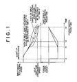
- FIG. 1 illustrates control timing and FIG. 2 illustrates control flow according to a preferred exemplary embodiment of the invention.
- the lower portion of FIG. 1 shows a change in the engine torque-down amount over time t after the start of the inertia phase.
- the input shaft rotational speed ⁇ t(tir) should become substantially equal to synchronous speed ⁇ t_af at the end of the shift (hereinafter referred to as "shift-end synchronous speed") at the target point for the end of the inertia phase, i.e., at the point at which the target inertia phase time tir has elapsed after the start of the inertia phase.
- shift-end synchronous speed synchronous speed
- the technology disclosed in JPA2-308934 required the creation of a map. According to this exemplary embodiment, however, this is not necessary. That is, according to this exemplary embodiment, the ECU 14 and the transmission control apparatus 16 work either in cooperation or separately so as to detect the appropriate torque-restore control starting point according to the dynamic model obtained by the Expression 1 below, and start that torque-restore control.
- a and B are constants determined by the inertia moment of various members in the transmission, the torque ratio of the torque converter during a shift, and the like
- Tc (t) is the torque transmission capacity of the clutch at time t
- the shift-end synchronous speed wt_af is first calculated according to information such as the gear speed and the like (100).
- the input shaft rotation speed ⁇ t(tir) is estimated and calculated from the dynamic model based on the target inertia phase time tir, which is set as a target beforehand, and the constants A and B of the integrated term, in addition to the input shaft rotation speed ⁇ t(t) detected successively by a sensor, not shown, the time derivative of that input shaft rotation speed ⁇ t(t), the torque transmission capacity T c (t) of the clutch in the automatic transmission 12, and the engine torque T e (t) (102).
- steps 100 to 106 are executed at predetermined intervals or at a predetermined frequency so it is possible that ⁇ t(tir) may not exactly equal ⁇ t_af in step 104. It is therefore preferable to actually have a little leeway within which they can be determined to substantially match (i.e., it is preferable to determine that they "substantially match" when the difference between them is substantially negligible). Also, the routine may be such that the torque-restore control starts when ⁇ t(tir) is less than ⁇ t_af.
- a dynamic model which shows the behavior of the automatic transmission (12) over time (t) from the start of the inertia phase.
- This dynamic model includes, for example, a linear term for the time (t) and a term obtained by integrating a torque transmission capacity in the clutch of the automatic transmission (12) and an amount of change over time in the engine torque.
- This dynamic model is used to estimate the input shaft rotational speed at the point at which the target inertia phase time (tir) has elapsed and start the torque-restore control at the point when it has been determined that that input shaft rotational speed ⁇ t(tir) substantially matches the shift-end synchronous speed ⁇ t_af. Accordingly, it is easy to obtain preferable synchronization at the point at which the shift ends, and a map need not be created to implement this control.
Landscapes
- Engineering & Computer Science (AREA)
- Chemical & Material Sciences (AREA)
- Combustion & Propulsion (AREA)
- Mechanical Engineering (AREA)
- Transportation (AREA)
- General Engineering & Computer Science (AREA)
- Automation & Control Theory (AREA)
- Control Of Transmission Device (AREA)
- Control Of Vehicle Engines Or Engines For Specific Uses (AREA)
- Control Of Driving Devices And Active Controlling Of Vehicle (AREA)
Applications Claiming Priority (2)
| Application Number | Priority Date | Filing Date | Title |
|---|---|---|---|
| JP2002289510A JP3750645B2 (ja) | 2002-10-02 | 2002-10-02 | 自動変速機の制御装置 |
| JP2002289510 | 2002-10-02 |
Publications (2)
| Publication Number | Publication Date |
|---|---|
| EP1405754A2 true EP1405754A2 (de) | 2004-04-07 |
| EP1405754A3 EP1405754A3 (de) | 2008-12-24 |
Family
ID=31987158
Family Applications (1)
| Application Number | Title | Priority Date | Filing Date |
|---|---|---|---|
| EP03022270A Withdrawn EP1405754A3 (de) | 2002-10-02 | 2003-10-01 | Steuervorrichtung und -verfahren für Automatikgetriebe |
Country Status (3)
| Country | Link |
|---|---|
| US (1) | US7169079B2 (de) |
| EP (1) | EP1405754A3 (de) |
| JP (1) | JP3750645B2 (de) |
Cited By (1)
| Publication number | Priority date | Publication date | Assignee | Title |
|---|---|---|---|---|
| EP2716894A4 (de) * | 2011-06-01 | 2015-01-21 | Nissan Motor | Steuerungsvorrichtung für ein mehrstufiges automatikgetriebe |
Families Citing this family (4)
| Publication number | Priority date | Publication date | Assignee | Title |
|---|---|---|---|---|
| KR100588541B1 (ko) * | 2003-11-17 | 2006-06-14 | 현대자동차주식회사 | 차량의 업시프트 변속시 엔진 제어방법 및 시스템 |
| JP2016205282A (ja) * | 2015-04-24 | 2016-12-08 | トヨタ自動車株式会社 | 車両統合制御装置 |
| US9573596B2 (en) | 2015-04-28 | 2017-02-21 | Cnh Industrial America Llc | Self-propelled off-road vehicle with system for torque control at shift points |
| JP6565879B2 (ja) * | 2016-11-30 | 2019-08-28 | トヨタ自動車株式会社 | 車両の変速制御装置 |
Citations (1)
| Publication number | Priority date | Publication date | Assignee | Title |
|---|---|---|---|---|
| JPH02308934A (ja) | 1989-05-25 | 1990-12-21 | Toyota Motor Corp | 自動変速機及びエンジンの一体制御装置 |
Family Cites Families (16)
| Publication number | Priority date | Publication date | Assignee | Title |
|---|---|---|---|---|
| DE2842389C2 (de) * | 1978-09-29 | 1984-04-12 | Robert Bosch Gmbh, 7000 Stuttgart | Vorrichtung zur Einstellung des Drehmomentes einer Brennkraftmaschine |
| DE3512604A1 (de) * | 1985-04-06 | 1986-10-16 | Daimler-Benz Ag, 7000 Stuttgart | Vorrichtung zur verminderung des motordrehmomentes bei einer umschaltung eines einem verbrennungsmotor nachgeschalteten gangwechselgetriebes |
| JPH0790719B2 (ja) | 1985-10-09 | 1995-10-04 | 日本電装株式会社 | 車両速度制御装置 |
| JP2522112Y2 (ja) * | 1989-09-12 | 1997-01-08 | 本田技研工業株式会社 | 自動変速機を備えた車両用の内燃機関の制御装置 |
| DE4327906B4 (de) * | 1993-08-19 | 2006-05-24 | Bayerische Motoren Werke Ag | Vorrichtung zur Reduzierung des Brennkraftmaschinenmoments bei Schaltvorgängen eines Getriebes |
| JPH08156652A (ja) * | 1994-12-07 | 1996-06-18 | Hitachi Ltd | 車両の駆動トルク制御装置 |
| DE19544516C3 (de) * | 1995-11-29 | 2003-12-11 | Siemens Ag | Steuereinrichtung für ein automatisches Kraftfahrzeuggetriebe |
| JP3599899B2 (ja) * | 1996-04-26 | 2004-12-08 | 本田技研工業株式会社 | 車両用内燃機関の出力トルク制御装置 |
| JP3515666B2 (ja) | 1996-07-11 | 2004-04-05 | ジヤトコ株式会社 | 自動変速機の変速制御装置 |
| DE19943334A1 (de) | 1999-09-10 | 2001-06-07 | Zahnradfabrik Friedrichshafen | Verfahren zur Regelung einer Kupplung oder einer Bremse in einem Getriebe |
| DE19962963B4 (de) * | 1999-12-24 | 2008-07-31 | Robert Bosch Gmbh | Verfahren und Vorrichtung zur Regelung einer Drehzahl eines Fahrzeugmotors mit Motorsteuerung während eines Schaltvorganges |
| US6364811B1 (en) * | 2000-03-20 | 2002-04-02 | General Motors Corporation | Model-based transmission upshift control with engine torque management |
| US6319168B1 (en) | 2000-04-25 | 2001-11-20 | General Motors Corporation | Apparatus and method for active transmission synchronization and shifting |
| US6319170B1 (en) * | 2000-05-19 | 2001-11-20 | General Motors Corporation | Model-based engine torque control for power-on downshifting in an automatic transmission |
| DE10204593A1 (de) * | 2002-02-05 | 2003-08-14 | Volkswagen Ag | Verfahren zum Betreiben einer Brennkraftmaschine eines Kraftfahrzeuges |
| US6656087B1 (en) * | 2002-06-11 | 2003-12-02 | General Motors Corporation | Multi-stage skip downshift control for an automatic transmission |
-
2002
- 2002-10-02 JP JP2002289510A patent/JP3750645B2/ja not_active Expired - Fee Related
-
2003
- 2003-09-23 US US10/667,451 patent/US7169079B2/en not_active Expired - Fee Related
- 2003-10-01 EP EP03022270A patent/EP1405754A3/de not_active Withdrawn
Patent Citations (1)
| Publication number | Priority date | Publication date | Assignee | Title |
|---|---|---|---|---|
| JPH02308934A (ja) | 1989-05-25 | 1990-12-21 | Toyota Motor Corp | 自動変速機及びエンジンの一体制御装置 |
Cited By (1)
| Publication number | Priority date | Publication date | Assignee | Title |
|---|---|---|---|---|
| EP2716894A4 (de) * | 2011-06-01 | 2015-01-21 | Nissan Motor | Steuerungsvorrichtung für ein mehrstufiges automatikgetriebe |
Also Published As
| Publication number | Publication date |
|---|---|
| US20040067817A1 (en) | 2004-04-08 |
| JP2004124802A (ja) | 2004-04-22 |
| JP3750645B2 (ja) | 2006-03-01 |
| EP1405754A3 (de) | 2008-12-24 |
| US7169079B2 (en) | 2007-01-30 |
Similar Documents
| Publication | Publication Date | Title |
|---|---|---|
| KR100504061B1 (ko) | 자동 변속기의 클러치 유압의 제어 장치와 제어 방법 | |
| EP0800022B1 (de) | Kupplungsdrucksteuerung zur Übersteuerung der ursprünglichen Getriebegangwahl bei einem automatischen Getriebe | |
| KR950033020A (ko) | 엔진플라이휠 토오크 결정방법 및 장치 | |
| JPH0577894B2 (de) | ||
| JP3317078B2 (ja) | 自動変速機の制御装置 | |
| KR100368712B1 (ko) | 자동변속기의제어방법및그제어장치및자동차 | |
| US7169079B2 (en) | Control apparatus and method for automatic transmission | |
| JPH11325232A (ja) | 自動変速機のクラッチ油圧の制御装置と制御方法 | |
| EP0849504A2 (de) | Schaltsteuerverfahren für Automatikgetriebe | |
| JP3193244B2 (ja) | 車両の駆動トルク制御装置 | |
| JP3261523B2 (ja) | 車両の制御装置 | |
| JP2003090423A (ja) | 流体式トルクコンバータのタービントルク算出装置、車両の駆動トルク制御装置 | |
| JPH0727217A (ja) | 自動変速機の油圧制御装置 | |
| JP2001520355A (ja) | トルクコンバータのロックアップクラッチを適応させる方法 | |
| JP4051779B2 (ja) | 車速制御装置 | |
| EP1748230B1 (de) | Vorrichtung für ein automatikgetriebe zur bestimmung der beendigung eines gangwechsels | |
| JP3267127B2 (ja) | パワートレーンの変速ショック軽減用総合制御装置 | |
| JPH1030466A (ja) | 自動変速機の変速制御装置 | |
| JP2973208B2 (ja) | 自動変速機の油圧制御装置 | |
| JP3492004B2 (ja) | 自動変速機におけるトルクコンバータのトルク比推定装置及びライン圧制御装置 | |
| JP3263830B2 (ja) | トルクコンバータ付自動変速機の故障診断装置 | |
| KR100551280B1 (ko) | 차량용 자동 변속기의 변속 제어 방법 | |
| JP4078866B2 (ja) | 自動変速機の回転速度推定装置および回転速度推定方法 | |
| JP2002333064A (ja) | 自動変速機の制御装置及び方法 | |
| JPH0835436A (ja) | 駆動力制御方法 |
Legal Events
| Date | Code | Title | Description |
|---|---|---|---|
| PUAI | Public reference made under article 153(3) epc to a published international application that has entered the european phase |
Free format text: ORIGINAL CODE: 0009012 |
|
| 17P | Request for examination filed |
Effective date: 20031001 |
|
| AK | Designated contracting states |
Kind code of ref document: A2 Designated state(s): AT BE BG CH CY CZ DE DK EE ES FI FR GB GR HU IE IT LI LU MC NL PT RO SE SI SK TR |
|
| AX | Request for extension of the european patent |
Extension state: AL LT LV MK |
|
| PUAL | Search report despatched |
Free format text: ORIGINAL CODE: 0009013 |
|
| AK | Designated contracting states |
Kind code of ref document: A3 Designated state(s): AT BE BG CH CY CZ DE DK EE ES FI FR GB GR HU IE IT LI LU MC NL PT RO SE SI SK TR |
|
| AX | Request for extension of the european patent |
Extension state: AL LT LV MK |
|
| AKX | Designation fees paid |
Designated state(s): DE FR |
|
| 17Q | First examination report despatched |
Effective date: 20110415 |
|
| RAP1 | Party data changed (applicant data changed or rights of an application transferred) |
Owner name: TOYOTA JIDOSHA KABUSHIKI KAISHA |
|
| STAA | Information on the status of an ep patent application or granted ep patent |
Free format text: STATUS: THE APPLICATION IS DEEMED TO BE WITHDRAWN |
|
| 18D | Application deemed to be withdrawn |
Effective date: 20180619 |
|
| RIC1 | Information provided on ipc code assigned before grant |
Ipc: B60K 41/08 19740701AFI20040115BHEP |