EP1403906B2 - Betriebsverfahren für ultraviolett-bestrahlungssystem - Google Patents
Betriebsverfahren für ultraviolett-bestrahlungssystem Download PDFInfo
- Publication number
- EP1403906B2 EP1403906B2 EP02733315.2A EP02733315A EP1403906B2 EP 1403906 B2 EP1403906 B2 EP 1403906B2 EP 02733315 A EP02733315 A EP 02733315A EP 1403906 B2 EP1403906 B2 EP 1403906B2
- Authority
- EP
- European Patent Office
- Prior art keywords
- lamp
- discharge lamp
- discharge lamps
- filament
- ultraviolet rays
- Prior art date
- Legal status (The legal status is an assumption and is not a legal conclusion. Google has not performed a legal analysis and makes no representation as to the accuracy of the status listed.)
- Expired - Lifetime
Links
Images

Classifications
-
- A—HUMAN NECESSITIES
- A61—MEDICAL OR VETERINARY SCIENCE; HYGIENE
- A61L—METHODS OR APPARATUS FOR STERILISING MATERIALS OR OBJECTS IN GENERAL; DISINFECTION, STERILISATION OR DEODORISATION OF AIR; CHEMICAL ASPECTS OF BANDAGES, DRESSINGS, ABSORBENT PADS OR SURGICAL ARTICLES; MATERIALS FOR BANDAGES, DRESSINGS, ABSORBENT PADS OR SURGICAL ARTICLES
- A61L2/00—Disinfection or sterilisation of materials or objects, in general; Accessories therefor
- A61L2/02—Disinfection or sterilisation of materials or objects, in general; Accessories therefor using physical processes
- A61L2/08—Radiation
- A61L2/10—Ultraviolet [UV] radiation
-
- C—CHEMISTRY; METALLURGY
- C02—TREATMENT OF WATER, WASTE WATER, SEWAGE, OR SLUDGE
- C02F—TREATMENT OF WATER, WASTE WATER, SEWAGE, OR SLUDGE
- C02F1/00—Treatment of water, waste water, or sewage
- C02F1/30—Treatment of water, waste water, or sewage by irradiation
- C02F1/32—Treatment of water, waste water, or sewage by irradiation with ultraviolet light
- C02F1/325—Irradiation devices or lamp constructions
-
- H—ELECTRICITY
- H01—ELECTRIC ELEMENTS
- H01J—ELECTRIC DISCHARGE TUBES OR DISCHARGE LAMPS
- H01J61/00—Gas-discharge or vapour-discharge lamps
- H01J61/70—Lamps with low-pressure unconstricted discharge having a cold pressure < 400 Torr
- H01J61/72—Lamps with low-pressure unconstricted discharge having a cold pressure < 400 Torr having a main light-emitting filling of easily vaporisable metal vapour, e.g. mercury
Definitions
- the present invention relates to a method using discharge lamps which radiate ultraviolet energy of a short wavelength range, in an ultraviolet ray irradiation apparatus
- the present invention is suitable for use in the fields of decomposition, sterilization, disinfection, etc. of organic substances.
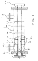
- FIG. 6 shows an example of a conventionally-known closed-type liquid treating or processing ultraviolet ray irradiation apparatus, where at least one discharge lamp 30 enclosed in an outer tube (protective tube) 20 is accommodated in a cylinder 1 made of stainless steel. Liquid to be treated or processed is introduced into the cylinder 1, so that ultraviolet rays are irradiated from the discharge lamp 30 onto the introduced liquid to be processed.
- the discharge lamp 30 used here is a low-pressure mercury vapor discharge lamp that radiates ultraviolet rays of a 185 nm wavelength (hereinafter also referred to as "185nm-wavelength ultraviolet rays").
- Light-emitting bulb 10 of the discharge lamp 30 is made of quartz glass having good transmissivity with respect to ultraviolet rays.
- the discharge lamp 30 is enclosed in the outer tube (protective tube) 20 transmissive to ultraviolet rays, so as to be isolated from the to-be-processed liquid in a liquid-tight manner.
- the outer tube 20 too is made of quartz glass having good transmissivity with respect to ultraviolet rays.
- the cylinder 1 is closed at its opposite ends with flanges 1a and 1b, and the to-be-processed liquid introduced via a liquid inlet 1c is subjected to irradiation of ultraviolet rays as it passes through the cylinder 1, and then discharged through a liquid outlet 1d.
- a plurality of (five in the illustrated example) reflux or baffle plates 1e - 1i are provided within the cylinder 1 between the liquid inlet 1c and the liquid outlet 1d, so as to prevent a short pass of the to-be-processed liquid flowing from the liquid inlet 1c toward the liquid outlet 1d. Note that although the liquid processing ultraviolet ray irradiation apparatus is shown in Fig.
- Ultraviolet rays emitted from the discharge lamp 30 pass through the outer tube 20 to be irradiated onto the to-be-processed liquid.
- the irradiated ultraviolet rays function to decompose any organic substances present in the liquid into harmless carbon monoxide (CO), carbon dioxide (CO 2 ) and water (H 2 O) as represented by the following mathematical expressions: H 2 O + h ⁇ (185 nm) ⁇ H + OH radical Cn Hm Ok + OH radical ⁇ CO, CO 2 and H 2 O , where n, m and k represent 1, 2, 3, ....
- the low-pressure mercury vapor discharge lamp known as a source for emitting short-wavelength ultraviolet rays
- the fluorescent lamp is a discharge lamp that converts ultraviolet rays of 254 nm wavelength into visible light by means of a fluorescent substance
- the sterilizing lamp is a discharge lamp that utilizes ultraviolet rays of 254 nm wavelength. While a variety of in-depth studies have been made of the irradiation of the 254nm-wavelength ultraviolet rays, it cannot be said that the 185nm-wavelength ultraviolet rays have attracted sufficient people's attention or have been studied sufficiently up to the present time.
- the European patent application EP 1 061 553 A1 describes a low-pressure mercury vapour discharge lamp which has an effective light emission length not shorter than 40 cm and a lamp input density not lower than 0.9W/cm and which contains at least mercury as a light-emitting metal and an activating rare gas, the mercury is provided in an amalgam with another metal, and a thin coating functioning to trap a very minute amount of the mercury is formed on a glass inner surface of the discharge lamp.
- an ultraviolet ray irradiating device which has high irradiation intensity in a vacuum ultraviolet ray area less than 200nm and is effective for a light source for photochemical reaction is described.
- power is supplied from a lighting circuit device to a low tension discharge lamp 1 is rectangular wave power and the power per unit length of an arc tube is high power more than 1,5W/cm.
- the ultraviolet ray irradiation intensity of 185nm is hightened so as to increase the resolving power of an organic chemical bonding.
- Tube portions of an approx. U-form light emitting tube are given a flat section, and flat surfaces of the tube portions are inclined in such a way as facing one another. Accordingly the electric discharge space in the light emitting tube is made flat, to cause decrease in the thickness of a mercury vapor layer, which suppresses self-absorption of ultraviolet rays due to the mercury vapor layer. From a wide light emission surface of each flat surface, ultraviolet rays are cast onto approx. the same place on the irradiation surface to cause increase in the ultraviolet dosage for the irradiation surface, which enhances the ultraviolet intensity.
- the Japanese patent application JP 9 017 377 A describes a mercury lamp lighting device and light quality improving device.
- a heat block is held by an arc tube clearance spacer, an arc tube temporarily pressing-down plate and an arc tube pressing-down plate.
- L-shaped heat kickers are installed on a side surface of the heat block.
- the heat block, the arc tube clearance spacer, the arc tube temporarily pressing-down plate, the arc tube pressing-down plate, the L-shaped heat kickers and plural cooling fins constitute a cooling jig to adjust mercury vapour pressure pHg in a lamp by cooling a tube surface around the electrode side of a light emitting tube.
- the Japanese patent application JP 7 021 809 A describes a road lamp comprising two sodium lamps being arranged inside of a reflecting mirror of a luminaire body.
- the respective sodium lamps are situated above and below, and are arranged mutually in the opposite direction.
- the two light emitting parts are formed respectively in the respective sodium lamps. Lighting control is carried out in order on the light emitting part being four in total. Thereby, the service life of the respective sodium lamps is lengthened, and the number of lamp replacing times can be reduced. Even if the light emitting parts are switched to/from each other, a light distributing pattern is not changed non-uniformly.
- a method according to claim 1 is provided.
- a discharge lamp adapted to radiate ultraviolet rays of a 185 nm wavelength
- said discharge lamp comprising a synthetic quartz glass tube having an inside diameter of 8 mm to 23 mm, and a pair of filaments provided within and at opposite ends of the glass tube with an L (cm) filament-to-filament distance, a mixture of rare gas and metal including at least mercury being sealed in an interior of the glass tube said discharge lamp being operated with a lamp current in a range of 0.4 A to 1.4A with an illuminating power source.
- An ultraviolet ray irradiation apparatus using the discharge lamp arranged in the above-mentioned manner comprises a processing apparatus that irradiates ultraviolet rays, emitted by the discharge lamp, onto an object to be processed. Because the ultraviolet ray irradiation apparatus employs the discharge lamp capable of radiating the 185nm-wavelength ultraviolet rays with an enhanced efficiency and having prolonged life, the irradiation apparatus can be an energy-saving type apparatus capable of operating at greatly reduced running costs.
- a method of using the ultraviolet ray irradiation apparatus arranged in the above-mentioned manner which comprises: installing a plurality of the discharge lamps in the processing apparatus; deilluminating a predetermined number of the plurality of the discharge lamps installed in the processing apparatus and illuminating the remaining discharge lamps; and varying a combination of the discharge lamps to be deilluminated and illuminated, in accordance with the passage of time.
- Fig. 1 shows a discharge lamp as used in an embodiment of the present invention.
- the discharge lamp 31 includes a light-emitting bulb or glass tube 11 made of synthetic quartz glass, a pair of filaments 21a and 21b disposed within and at opposite ends of the glass tube 11, seal sections 2a and 2b attached to the opposite ends of the glass tube 11, and bulb bases 3a and 3b attached to opposite ends of the discharge lamp 31.
- the filaments 21a and 21b each have coated thereon an emitter that is made, for example, of barium oxide.
- the filament 21a is held by a pair of inner leads 22a and 22b projecting inwardly from the seal section 2a, and similarly the other filament 21b is held by a pair of inner leads 22c and 22d projecting inwardly from the seal section 2b.
- the bulb bases 3a and 3b are each made of ceramics, and one of the bulb bases 3a is provided with a pair of electric terminals 31a and 31b.
- the seal sections 2a and 2b function to electrically connect the filaments 21a, 21b and the electric terminals 31a, 31b via outer leads 25a, 25b and 26 while keeping gas tightness by means of molybdenum films 24a - 24d.
- Mercury of about 20 mg in weight and rare gas of about 400 Pa are sealed together in the glass tube 11.
- the discharge lamp 31 is constructed as a two-terminal type discharge lamp, although the invention is not necessarily limited to the two-terminal type. Namely, one of the filaments 21a is connected at its one end to the electric terminal 31a via the inner lead 22b, molybdenum film 24b and outer lead 25a, while the other filament 21b is connected at its one end to the other electric terminal 31b via the inner lead 22c, molybdenum film 24c and outer leads 25a and 26.
- the discharge lamp 31 in accordance with the instant embodiment is characterized in that the glass tube 11 is made of synthetic quartz glass and various dimensions of the discharge lamp 31, such as the inside diameter of the bulb or glass tube and distance between the filaments (filament-to-filament distance), are set on the basis of a predetermined condition such that ultraviolet rays of a 185 nm wavelength can be emitted with an enhanced efficiency.
- the inventor of the present invention and the like prepared a plurality of the low-pressure mercury vapor discharge lamps 31 of various sizes each having the basic construction as shown in Fig. 1 , and conducted various experiments on these low-pressure mercury vapor discharge lamps 31 to evaluate relationship between electrical characteristics of the discharge lamps 31 and intensity of the 185nm-wavelength ultraviolet rays emitted therefrom.
- the low-pressure mercury vapor discharge lamps 31 employed in the experiments had synthetic quartz glass tubes which have respective inside diameters of 8 mm, 13 mm, 18 mm and 23 mm, wall thickness of 1 mm and lengths of 100 - 160 cm. Further, in these discharge lamps 31, the filament-to-filament distance L (cm) was set to 95 - 153 cm.
- the discharge lamps 31 to be tested were each inserted in a T-shaped glass tube having a branch tube attached to a central portion thereof for measuring intensity of 185nm-wavelength ultraviolet rays.
- the interior of the T-shaped glass tube was filled with a nitrogen atmosphere, and cooling water was caused to flow along the outer surface of the T-shaped glass tube.
- the illuminating power source was provided with two types of ballasts, an electronic ballast of about 40 kHz and an electromagnetic ballast of a commercial frequency, and five different current levels of 0.4A (ampere), 0.6A, 0.8A, 1.0A and 1.4A were set, as the lamp current during illumination, for the discharge lamps 31.
- the 185nm-wavelength ultraviolet rays were measured using an ultraviolet ray intensity meter "UV-185" (trademark) commercially available from ORC Manufacturing Co., Ltd., Tokyo, Japan.
- the temperature of a coldest section of the discharge lamp, where superfluous mercury stays can be changed, with the result that the mercury vapor pressure can be changed.
- the lamp voltage depends on the mercury vapor pressure, i.e. amount of mercury vaporization, within the discharge lamp
- changing the temperature of the coldest section of the discharge lamp as noted above can variably set the lamp voltage V.
- the lamp current I is also a constant factor determined by a ballast used, and so the lamp voltage V is a main factor that can control the intensity of the 185nm-wavelength ultraviolet rays.
- the measure of the intensity of the 185nm-wavelength ultraviolet rays was processed from the viewpoint of "ultraviolet ray intensity per electric power consumed"; namely, the measured intensity value of the 185nm-wavelength ultraviolet rays was divided by the measured value of the lamp power, and the resultant quotient was set as an index of "radiation efficiency" for the 185nm-wavelength ultraviolet rays.
- the measure of the lamp voltage was processed from the viewpoint of "voltage per unit length”; namely, the fixed value of the anode voltage drop Vf (V) was subtracted from the measured value of the lamp voltage V (V), and the resultant difference "V - Vf" was divided by the filament-to-filament distance L.
- the resultant quotient was set as a "potential inclination", i.e. as a lamp voltage per unit length of the filament-to-filament distance.
- a “potential inclination” i.e. as a lamp voltage per unit length of the filament-to-filament distance.
- the measured results are plotted in the figure with the horizontal axis representing the value of the "potential inclination” and the vertical axis representing the value of the "radiation efficiency of the 185nm-wavelength ultraviolet rays".
- the lamp voltage V was changed by changing the temperature of the cooling water as noted above. From Fig. 2 , it can be seen that the "radiation efficiency of the 185nm-wavelength ultraviolet rays" presents a highest value (about “6") when the “potential inclination” is about 0.88 (V / cm). This means that by just setting the various physical and electronic conditions such that the "radiation efficiency of the 185nm-wavelength ultraviolet rays" falls within an appropriate admissible range including the highest or peak value (about “6" in the illustrated example of Fig. 2 ), there can be provided a highly-improved discharge lamp and ultraviolet ray irradiation apparatus capable of irradiating 185nm-wavelength ultraviolet rays with a high efficiency.
- Fig. 3 is a graph showing the thus-obtained "optimal potential inclination” (plotted on the horizontal axis) for each of the various lamp current values (plotted on the vertical axis). From Fig. 3 . it can be seen that the "optimal potential inclination" is almost in inverse proportion to the square root of the lamp current value (I)(i.e., ⁇ I) .
- synthetic quartz glass is used as the light emitting bulb or tube of the discharge lamp.
- the synthetic quartz glass is manufactured using silicon tetrachloride as its starting material, contains an extremely small amount of impurities, and has a good transmissivity with respect to ultraviolet rays of short wavelengths.
- the glass tube which inherently has a low transmissivity with respect to ultraviolet rays of short wavelengths, absorbs more 185nm-wavelength ultraviolet rays as the radiation efficiency for 185 nm wavelength increases, so that the glass itself changes in quality to produce cloudiness or opacity and thus the transmissivity with respect to the 185nm-wavelength ultraviolet rays decreases due to the opacity. It is thus considered that there would occurs a repetition of the cycle of further transmissivity decrease and quality change and this repetition of the cycle results in a rapid decrease in the transmissivity with respect to the 185nm-wavelength ultraviolet rays. Therefore, it is essential for the present invention to employ the synthetic quartz glass tube.
- the organic-substance decomposing apparatus i.e. ultraviolet ray irradiation apparatus, employing the discharge lamp is suitably applicable to, for example, production of ultrapure water for use in semiconductor manufacture.
- the ultraviolet ray irradiation apparatus must stand long-time continuous operation for one to three years. Because the synthetic quartz glass has a superior transmissivity with respect to ultraviolet ray at its initial stage of use life and contains a very small amount of impurities that would become a main cause of quality change, it can keep a high radiation efficiency of ultraviolet rays even when the ultraviolet ray irradiation apparatus is operated in an environment where the radiation rate of 185nm-wavelength ultraviolet rays is high.
- the ultraviolet ray irradiation apparatus employing the discharge lamp is applicable to a variety of fields, other than the semiconductor manufacturing, that require decomposition, sterilization, disinfection, etc. of organic substances, such as beverage manufacture, food manufacture, medical treatment, water processing, etc.
- Fig. 5 is a graph showing actual measured data obtained by use of a conventional ultraviolet ray irradiation apparatus B provided with a conventional discharge lamp and the ultraviolet ray irradiation apparatus A provided with the above discharge lamp. More specifically, Fig. 5 comparatively shows the processing capabilities of the two apparatus in processing raw water having a TOC (Total Organic Carbon) density of 10 ppb into water of 1 ppb or below, in terms of a flow rate per unit power consumption amount. In the figure, a value representing the processing capability of the conventional ultraviolet ray irradiation apparatus B at its initial stage of use is given as 100 %.
- TOC Total Organic Carbon
- the high processing capability as set forth above also allows the ultraviolet ray irradiation apparatus to operate while effecting thinned-out illumination of the discharge lamps, which could advantageously lead to saving in maintenance as well as in energy as will be explained below.
- a plurality of the discharge lamps are installed in a processing apparatus that uses the discharge lamps to perform processes, such as organic-substance decomposition, sterilization, disinfection, etc., on a predetermined object to be processed (liquid, solid object or the like). Then, the so-called thinned-out illumination is carried out by deilluminating a predetermined number of the installed discharge lamps and illuminating only the remaining discharge lamps, and the combination of the selectively deilluminated and illuminated discharge lamps is varied as appropriate in accordance with the passage of time.
- n is an arbitrary integral number greater than 2
- another example of the method for using the ultraviolet ray irradiation apparatus which constructs an ultraviolet ray irradiation apparatus by installing n (the same number as in the conventional technique) discharge lamps capable of high-efficiency radiation, more than the m discharge lamps to be illuminated concurrently, and illuminates the n discharge lamps in the thinned-out fashion.
- the discharge lamp itself may be of any other construction than the type shown in Fig. 1 , as long as it satisfies the requirements of the characteristics claimed.
- a discharge lamp having sealed therein an amalgam of mercury and other metal can achieve the same advantageous results as discussed above.
- operation and advantageous results, similar to those discussed above, can be obtained by a continuous-heating type discharge lamp that constantly heats the filaments, or a discharge lamp of a type having filaments and anode provided in parallel, or a two-base type discharge lamp having charging pins projecting outwardly from opposite ends thereof, as long as the discharge lamp is a low-pressure mercury vapor discharge lamp.
- the discharge lamp may include four terminals or the like rather than the two terminals 31a and 31b as shown in Fig. 1 .
- the present invention permits effective savings in energy and maintenance.
Landscapes
- Health & Medical Sciences (AREA)
- Life Sciences & Earth Sciences (AREA)
- Animal Behavior & Ethology (AREA)
- General Health & Medical Sciences (AREA)
- Engineering & Computer Science (AREA)
- Environmental & Geological Engineering (AREA)
- Water Supply & Treatment (AREA)
- Chemical & Material Sciences (AREA)
- Organic Chemistry (AREA)
- Epidemiology (AREA)
- Toxicology (AREA)
- Hydrology & Water Resources (AREA)
- Public Health (AREA)
- Veterinary Medicine (AREA)
- Physical Water Treatments (AREA)
- Apparatus For Disinfection Or Sterilisation (AREA)
- Discharge Lamps And Accessories Thereof (AREA)
- Physical Or Chemical Processes And Apparatus (AREA)
- Heating, Cooling, Or Curing Plastics Or The Like In General (AREA)
- Application Of Or Painting With Fluid Materials (AREA)
- Vessels And Coating Films For Discharge Lamps (AREA)
Claims (1)
- Verfahren der Benutzung einer Ultraviolett-Bestrahlungsvorrichtung, wobei das Verfahren folgendes aufweist:Installieren mehrerer Entladungslampen (31) in einer Bearbeitungsvorrichtung, die von den Entladungslampen emittierte ultraviolette Strahlen auf ein zu bearbeitendes Objekt einstrahlt, wobei jede der mehreren Entladungslampen (31):- zum Abstrahlen ultravioletter Strahlen einer Wellenlänge von 185 nm ausgelegt ist,- eine synthetische Quarzglasröhre (11) mit einem Innendurchmesser von 8 mm bis 23 mm und ein Paar innerhalb und an entgegengesetzten Enden der Glasröhre vorgesehener Fäden (21a, 21b) mit einem Abstand L (cm) von Faden zu Faden aufweist, wobei ein Gemisch von Edelgas und Metall, zumindest Quecksilber umfassend, im Inneren der Glasröhre (11) eingeschlossen ist, und- mit einem Strom in einem Bereich von 0,4 A bis 1,4 A betrieben wirdNicht-Erleuchten einer vorherbestimmten Anzahl der mehreren in der Bearbeitungsvorrichtung installierten Entladungslampen (31) und Erleuchten der übrigen Anzahl der Entladungslampen (31), undVerändern einer Kombination der nicht zu erleuchtenden und zu erleuchtenden Entladungslampen (31) entsprechend zeitlichem Ablauf,wobei eine Lampenspannung V (V) und Lampenstrom I (A) während des Betriebs jeder der Entladungslampen (31), Abstand L (cm) von Faden zu Faden und der Innendurchmesser D (mm) der Glasröhre (11) in einer Beziehung zueinander stehen, die durch den folgenden mathematischen Ausdruck abgebildet wird:wobei Vf ein konstanter Faktor ist, der von der Beleuchtungsleistungsquelle abhängt, und wobei, wenn die Entladungslampen (31) mit einer Hochfrequenzleistungsquelle von 1 kHz oder darüber erleuchtet werden, Vf 10 ist, aber wenn die Entladungslampen (31) mit einer Leistungsquelle von unter 1 kHz erleuchtet werden, Vf 50 ist.

Applications Claiming Priority (3)
| Application Number | Priority Date | Filing Date | Title |
|---|---|---|---|
| JP2001179972 | 2001-06-14 | ||
| JP2001179972A JP3563373B2 (ja) | 2001-06-14 | 2001-06-14 | 放電灯および紫外線照射装置並びにその運用方法 |
| PCT/JP2002/005549 WO2002103749A1 (en) | 2001-06-14 | 2002-06-05 | Discharge lamp and ultraviolet irradiation system and operation method therefor |
Publications (4)
| Publication Number | Publication Date |
|---|---|
| EP1403906A1 EP1403906A1 (de) | 2004-03-31 |
| EP1403906A4 EP1403906A4 (de) | 2006-09-20 |
| EP1403906B1 EP1403906B1 (de) | 2011-03-16 |
| EP1403906B2 true EP1403906B2 (de) | 2014-08-20 |
Family
ID=19020458
Family Applications (1)
| Application Number | Title | Priority Date | Filing Date |
|---|---|---|---|
| EP02733315.2A Expired - Lifetime EP1403906B2 (de) | 2001-06-14 | 2002-06-05 | Betriebsverfahren für ultraviolett-bestrahlungssystem |
Country Status (9)
| Country | Link |
|---|---|
| US (1) | US6683411B2 (de) |
| EP (1) | EP1403906B2 (de) |
| JP (1) | JP3563373B2 (de) |
| KR (1) | KR100854564B1 (de) |
| CN (1) | CN100474497C (de) |
| AT (1) | ATE502392T1 (de) |
| DE (1) | DE60239461D1 (de) |
| TW (1) | TWI223829B (de) |
| WO (1) | WO2002103749A1 (de) |
Families Citing this family (15)
| Publication number | Priority date | Publication date | Assignee | Title |
|---|---|---|---|---|
| JP4516251B2 (ja) * | 2001-11-07 | 2010-08-04 | 株式会社日本フォトサイエンス | 紫外線照射装置及びその運用方法 |
| DE102004048005A1 (de) * | 2004-10-01 | 2006-04-13 | Dr. Hönle AG | Gasentladungslampe, System und Verfahren zum Härten von durch UV-Licht härtbare Materialien sowie durch UV-Licht gehärtetes Material |
| CN1977978B (zh) * | 2005-12-01 | 2011-07-06 | 福建新大陆环保科技有限公司 | 一种开放式水渠辐射消毒系统 |
| JP2007220549A (ja) * | 2006-02-17 | 2007-08-30 | Photoscience Japan Corp | 短波長紫外線放電灯及び紫外線照射処理装置 |
| US20070241288A1 (en) * | 2006-04-17 | 2007-10-18 | Tsung-Yang Wang | Ultraviolet lamp for water sterilization |
| JP5092329B2 (ja) * | 2006-09-26 | 2012-12-05 | 栗田工業株式会社 | 短波長紫外線放電灯及び紫外線照射処理装置 |
| US7688050B2 (en) * | 2006-11-01 | 2010-03-30 | Semiconductor Components Industries, Llc | Switching power supply controller with unidirectional transient gain change |
| US9536728B2 (en) * | 2007-02-15 | 2017-01-03 | Applied Material, Inc. | Lamp for rapid thermal processing chamber |
| JP5644039B2 (ja) * | 2008-08-29 | 2014-12-24 | ウシオ電機株式会社 | 紫外線を放射する蛍光ランプおよびその製造方法 |
| JP2012114007A (ja) * | 2010-11-26 | 2012-06-14 | Ushio Inc | 放電ランプ装置 |
| CN103464060A (zh) * | 2013-09-03 | 2013-12-25 | 上海师范大学 | 一种全天候光/电催化反应装置 |
| CN103463666B (zh) * | 2013-09-27 | 2015-06-24 | 何志明 | 一种紫外灭菌消毒装置及其设置方法 |
| KR101706277B1 (ko) * | 2015-09-25 | 2017-02-23 | (주)시테코 | 살균장치 |
| CN105470100B (zh) * | 2016-01-06 | 2018-03-09 | 佛山柯维光电股份有限公司 | 一种高185nm辐射效率的紫外线灯 |
| WO2019151364A1 (ja) * | 2018-02-02 | 2019-08-08 | 株式会社エンプラス | 紫外線殺菌管および紫外線殺菌装置 |
Family Cites Families (21)
| Publication number | Priority date | Publication date | Assignee | Title |
|---|---|---|---|---|
| DE2616893A1 (de) * | 1976-04-15 | 1977-11-03 | Patra Patent Treuhand | Bestrahlungslampe |
| GB2060243B (en) * | 1979-10-05 | 1983-05-05 | Pye Electronic Prod Ltd | Spectral discharge lamp |
| JPH0649787B2 (ja) * | 1990-01-23 | 1994-06-29 | 工業技術院長 | 成形品の表面処理及び塗装方法 |
| JPH04109952A (ja) * | 1990-08-31 | 1992-04-10 | Toshiba Lighting & Technol Corp | 紫外線照射装置 |
| JPH04303448A (ja) * | 1991-03-29 | 1992-10-27 | Toshiba Lighting & Technol Corp | 紫外線照射装置 |
| JP3142608B2 (ja) | 1991-08-08 | 2001-03-07 | 株式会社日本フォトサイエンス | 光化学反応処理方法 |
| JPH0589835A (ja) * | 1991-09-27 | 1993-04-09 | Toshiba Lighting & Technol Corp | 紫外線光源および紫外線照射装置 |
| US5569979A (en) * | 1992-02-28 | 1996-10-29 | General Electric Company | UV absorbing fused quartz and its use for lamp envelopes |
| JPH05258718A (ja) | 1992-03-09 | 1993-10-08 | Iwasaki Electric Co Ltd | 高負荷形紫外用金属蒸気放電灯 |
| JPH0721982A (ja) | 1993-06-30 | 1995-01-24 | Toshiba Lighting & Technol Corp | 低圧水銀ランプおよびこれを用いた紫外線照射装置 |
| JP4008964B2 (ja) * | 1993-06-30 | 2007-11-14 | 東芝ライテック株式会社 | 照明器具 |
| JP3509256B2 (ja) * | 1995-01-31 | 2004-03-22 | 岩崎電気株式会社 | 紫外線殺菌用低圧水銀放電灯及びその製造方法 |
| JPH097377A (ja) * | 1995-06-20 | 1997-01-10 | Sony Corp | 強誘電体記憶装置 |
| JPH0917377A (ja) * | 1995-06-30 | 1997-01-17 | Toshiba Lighting & Technol Corp | 水銀ランプ点灯装置及び光改質装置 |
| AU712563B2 (en) * | 1995-10-24 | 1999-11-11 | Auckland Uniservices Limited | Inductively powered lighting |
| JPH09212976A (ja) * | 1996-02-02 | 1997-08-15 | Fujitsu Ten Ltd | 再生装置 |
| DE19613502C2 (de) * | 1996-04-04 | 1998-07-09 | Heraeus Noblelight Gmbh | Langlebiger Excimerstrahler und Verfahren zu seiner Herstellung |
| US5912934A (en) * | 1996-07-15 | 1999-06-15 | Remote Ocean Systems, Inc. | Underwater inspection system for nuclear power facilities |
| JPH10151448A (ja) | 1996-11-21 | 1998-06-09 | Nippon Photo Sci:Kk | 光照射装置の光照射ランプのメンテナンス方法 |
| JP3648905B2 (ja) | 1997-01-24 | 2005-05-18 | 岩崎電気株式会社 | 水銀蒸気放電灯 |
| JP4025462B2 (ja) | 1999-06-11 | 2007-12-19 | 株式会社日本フォトサイエンス | 低圧水銀蒸気放電灯およびそれを使用した紫外線照射装置 |
-
2001
- 2001-06-14 JP JP2001179972A patent/JP3563373B2/ja not_active Expired - Fee Related
- 2001-11-13 US US09/998,804 patent/US6683411B2/en not_active Expired - Lifetime
-
2002
- 2002-06-05 KR KR1020037002059A patent/KR100854564B1/ko not_active Expired - Lifetime
- 2002-06-05 EP EP02733315.2A patent/EP1403906B2/de not_active Expired - Lifetime
- 2002-06-05 CN CNB028020707A patent/CN100474497C/zh not_active Expired - Lifetime
- 2002-06-05 WO PCT/JP2002/005549 patent/WO2002103749A1/ja not_active Ceased
- 2002-06-05 DE DE60239461T patent/DE60239461D1/de not_active Expired - Lifetime
- 2002-06-05 AT AT02733315T patent/ATE502392T1/de not_active IP Right Cessation
- 2002-06-07 TW TW091112274A patent/TWI223829B/zh not_active IP Right Cessation
Non-Patent Citations (2)
| Title |
|---|
| "Technical Bulletin "DRS 080592 GER Germicidal Lamps"", 1992, LIGHT SOURCES INC. † |
| "Technical Bulletin "Suprasil 1,2,3 SUPRASIL STANDARDS"", March 1998, HERAEUS † |
Also Published As
| Publication number | Publication date |
|---|---|
| EP1403906A4 (de) | 2006-09-20 |
| WO2002103749A1 (en) | 2002-12-27 |
| CN1463465A (zh) | 2003-12-24 |
| US20020190227A1 (en) | 2002-12-19 |
| KR100854564B1 (ko) | 2008-08-26 |
| JP3563373B2 (ja) | 2004-09-08 |
| US6683411B2 (en) | 2004-01-27 |
| ATE502392T1 (de) | 2011-04-15 |
| EP1403906A1 (de) | 2004-03-31 |
| EP1403906B1 (de) | 2011-03-16 |
| DE60239461D1 (de) | 2011-04-28 |
| CN100474497C (zh) | 2009-04-01 |
| JP2002373625A (ja) | 2002-12-26 |
| KR20030036690A (ko) | 2003-05-09 |
| TWI223829B (en) | 2004-11-11 |
Similar Documents
| Publication | Publication Date | Title |
|---|---|---|
| EP1403906B2 (de) | Betriebsverfahren für ultraviolett-bestrahlungssystem | |
| CN1160258C (zh) | 由uv-c气体放电灯组成的用于消毒水的装置 | |
| WO2002005311A1 (en) | Treating apparatus utilizing ultraviolet ray | |
| TW570816B (en) | Ultraviolet ray irradiation device and operation method thereof | |
| US20090120882A1 (en) | Device for Treating Fluids, Especially Water Sterilization, Comprising an Electrodeless Gas Discharge Lamp | |
| KR100730451B1 (ko) | 자외광원 점등장치 및 자외선 조사장치 | |
| GB2182486A (en) | Magnesium vapor discharge lamp | |
| JP4959072B2 (ja) | 光化学反応処理装置および光化学反応処理方法 | |
| TWI234180B (en) | Ultraviolet-ray liquid treating apparatus | |
| CN1298422C (zh) | 光化学反应处理装置和光化学反应处理方法 | |
| Golovitskiı̆ | Low-pressure inductive rf discharge in a rare gas-halogen mixture for economical mercury-free luminescence light sources. | |
| US7733027B2 (en) | High-pressure mercury vapor lamp incorporating a predetermined germanium to oxygen molar ratio within its discharge fill | |
| CN100391858C (zh) | 紫外线液体处理装置和处理方法 | |
| JP3198519B2 (ja) | 紫外線照射装置 | |
| JPH0871546A (ja) | 液体処理用紫外線照射装置 | |
| JPH07326322A (ja) | 低圧水銀ランプおよびこれを用いた紫外線照射装置 | |
| JPH0589836A (ja) | 紫外線放射光源、点灯装置および紫外線照射装置 | |
| JPH0745238A (ja) | 低圧水銀ランプの点灯方法および低圧水銀ランプの点灯装置ならびにこれを用いた紫外線照射装置 | |
| Lapatovich | Recent advances in lighting science | |
| JPH0721982A (ja) | 低圧水銀ランプおよびこれを用いた紫外線照射装置 | |
| Shuaibov et al. | Electric-discharge source of steady-state UV-VUV radiation from iodine atoms and iodine-containing molecules | |
| JPH113686A (ja) | 放電容器、無電極放電ランプ、無電極放電ランプ装置および照明装置 | |
| JPH09265952A (ja) | 放電ランプ、ランプ点灯装置、紫外線放射装置および流体殺菌装置 | |
| JP2002251983A (ja) | 無電極放電ランプ装置および紫外線照射装置 | |
| JPH04112446A (ja) | 低圧放電灯 |
Legal Events
| Date | Code | Title | Description |
|---|---|---|---|
| PUAI | Public reference made under article 153(3) epc to a published international application that has entered the european phase |
Free format text: ORIGINAL CODE: 0009012 |
|
| 17P | Request for examination filed |
Effective date: 20031222 |
|
| AK | Designated contracting states |
Kind code of ref document: A1 Designated state(s): AT BE CH CY DE DK ES FI FR GB GR IE IT LI LU MC NL PT SE TR |
|
| A4 | Supplementary search report drawn up and despatched |
Effective date: 20060818 |
|
| 17Q | First examination report despatched |
Effective date: 20090330 |
|
| GRAP | Despatch of communication of intention to grant a patent |
Free format text: ORIGINAL CODE: EPIDOSNIGR1 |
|
| GRAS | Grant fee paid |
Free format text: ORIGINAL CODE: EPIDOSNIGR3 |
|
| GRAA | (expected) grant |
Free format text: ORIGINAL CODE: 0009210 |
|
| AK | Designated contracting states |
Kind code of ref document: B1 Designated state(s): AT BE CH CY DE DK ES FI FR GB GR IE IT LI LU MC NL PT SE TR |
|
| REG | Reference to a national code |
Ref country code: GB Ref legal event code: FG4D |
|
| REG | Reference to a national code |
Ref country code: CH Ref legal event code: EP |
|
| REG | Reference to a national code |
Ref country code: IE Ref legal event code: FG4D |
|
| REF | Corresponds to: |
Ref document number: 60239461 Country of ref document: DE Date of ref document: 20110428 Kind code of ref document: P |
|
| REG | Reference to a national code |
Ref country code: DE Ref legal event code: R096 Ref document number: 60239461 Country of ref document: DE Effective date: 20110428 |
|
| REG | Reference to a national code |
Ref country code: CH Ref legal event code: NV Representative=s name: FREI PATENTANWALTSBUERO AG |
|
| REG | Reference to a national code |
Ref country code: NL Ref legal event code: T3 |
|
| PG25 | Lapsed in a contracting state [announced via postgrant information from national office to epo] |
Ref country code: SE Free format text: LAPSE BECAUSE OF FAILURE TO SUBMIT A TRANSLATION OF THE DESCRIPTION OR TO PAY THE FEE WITHIN THE PRESCRIBED TIME-LIMIT Effective date: 20110316 Ref country code: ES Free format text: LAPSE BECAUSE OF FAILURE TO SUBMIT A TRANSLATION OF THE DESCRIPTION OR TO PAY THE FEE WITHIN THE PRESCRIBED TIME-LIMIT Effective date: 20110627 Ref country code: GR Free format text: LAPSE BECAUSE OF FAILURE TO SUBMIT A TRANSLATION OF THE DESCRIPTION OR TO PAY THE FEE WITHIN THE PRESCRIBED TIME-LIMIT Effective date: 20110617 |
|
| PG25 | Lapsed in a contracting state [announced via postgrant information from national office to epo] |
Ref country code: CY Free format text: LAPSE BECAUSE OF FAILURE TO SUBMIT A TRANSLATION OF THE DESCRIPTION OR TO PAY THE FEE WITHIN THE PRESCRIBED TIME-LIMIT Effective date: 20110316 Ref country code: FI Free format text: LAPSE BECAUSE OF FAILURE TO SUBMIT A TRANSLATION OF THE DESCRIPTION OR TO PAY THE FEE WITHIN THE PRESCRIBED TIME-LIMIT Effective date: 20110316 Ref country code: AT Free format text: LAPSE BECAUSE OF FAILURE TO SUBMIT A TRANSLATION OF THE DESCRIPTION OR TO PAY THE FEE WITHIN THE PRESCRIBED TIME-LIMIT Effective date: 20110316 |
|
| PG25 | Lapsed in a contracting state [announced via postgrant information from national office to epo] |
Ref country code: BE Free format text: LAPSE BECAUSE OF FAILURE TO SUBMIT A TRANSLATION OF THE DESCRIPTION OR TO PAY THE FEE WITHIN THE PRESCRIBED TIME-LIMIT Effective date: 20110316 |
|
| PG25 | Lapsed in a contracting state [announced via postgrant information from national office to epo] |
Ref country code: PT Free format text: LAPSE BECAUSE OF FAILURE TO SUBMIT A TRANSLATION OF THE DESCRIPTION OR TO PAY THE FEE WITHIN THE PRESCRIBED TIME-LIMIT Effective date: 20110718 |
|
| PLBI | Opposition filed |
Free format text: ORIGINAL CODE: 0009260 |
|
| 26 | Opposition filed |
Opponent name: HERAEUS NOBLELIGHT GMBH Effective date: 20111108 |
|
| PLAX | Notice of opposition and request to file observation + time limit sent |
Free format text: ORIGINAL CODE: EPIDOSNOBS2 |
|
| REG | Reference to a national code |
Ref country code: DE Ref legal event code: R026 Ref document number: 60239461 Country of ref document: DE Effective date: 20111108 |
|
| PLAF | Information modified related to communication of a notice of opposition and request to file observations + time limit |
Free format text: ORIGINAL CODE: EPIDOSCOBS2 |
|
| REG | Reference to a national code |
Ref country code: IE Ref legal event code: MM4A |
|
| PG25 | Lapsed in a contracting state [announced via postgrant information from national office to epo] |
Ref country code: IE Free format text: LAPSE BECAUSE OF NON-PAYMENT OF DUE FEES Effective date: 20110605 |
|
| PG25 | Lapsed in a contracting state [announced via postgrant information from national office to epo] |
Ref country code: IT Free format text: LAPSE BECAUSE OF FAILURE TO SUBMIT A TRANSLATION OF THE DESCRIPTION OR TO PAY THE FEE WITHIN THE PRESCRIBED TIME-LIMIT Effective date: 20110316 |
|
| PLBB | Reply of patent proprietor to notice(s) of opposition received |
Free format text: ORIGINAL CODE: EPIDOSNOBS3 |
|
| PG25 | Lapsed in a contracting state [announced via postgrant information from national office to epo] |
Ref country code: MC Free format text: LAPSE BECAUSE OF NON-PAYMENT OF DUE FEES Effective date: 20110630 |
|
| PG25 | Lapsed in a contracting state [announced via postgrant information from national office to epo] |
Ref country code: LU Free format text: LAPSE BECAUSE OF NON-PAYMENT OF DUE FEES Effective date: 20110605 |
|
| PG25 | Lapsed in a contracting state [announced via postgrant information from national office to epo] |
Ref country code: TR Free format text: LAPSE BECAUSE OF FAILURE TO SUBMIT A TRANSLATION OF THE DESCRIPTION OR TO PAY THE FEE WITHIN THE PRESCRIBED TIME-LIMIT Effective date: 20110316 |
|
| RIC2 | Information provided on ipc code assigned after grant |
Ipc: C02F 1/32 20060101ALI20131205BHEP Ipc: H01J 61/72 20060101AFI20131205BHEP Ipc: A61L 2/10 20060101ALI20131205BHEP |
|
| PUAH | Patent maintained in amended form |
Free format text: ORIGINAL CODE: 0009272 |
|
| STAA | Information on the status of an ep patent application or granted ep patent |
Free format text: STATUS: PATENT MAINTAINED AS AMENDED |
|
| 27A | Patent maintained in amended form |
Effective date: 20140820 |
|
| AK | Designated contracting states |
Kind code of ref document: B2 Designated state(s): AT BE CH CY DE DK ES FI FR GB GR IE IT LI LU MC NL PT SE TR |
|
| REG | Reference to a national code |
Ref country code: DE Ref legal event code: R102 Ref document number: 60239461 Country of ref document: DE |
|
| REG | Reference to a national code |
Ref country code: CH Ref legal event code: AELC |
|
| REG | Reference to a national code |
Ref country code: DE Ref legal event code: R102 Ref document number: 60239461 Country of ref document: DE Effective date: 20140820 |
|
| REG | Reference to a national code |
Ref country code: NL Ref legal event code: T3 |
|
| REG | Reference to a national code |
Ref country code: FR Ref legal event code: PLFP Year of fee payment: 15 |
|
| REG | Reference to a national code |
Ref country code: FR Ref legal event code: PLFP Year of fee payment: 16 |
|
| REG | Reference to a national code |
Ref country code: FR Ref legal event code: PLFP Year of fee payment: 17 |
|
| REG | Reference to a national code |
Ref country code: CH Ref legal event code: PCAR Free format text: NEW ADDRESS: POSTFACH, 8032 ZUERICH (CH) |
|
| PGFP | Annual fee paid to national office [announced via postgrant information from national office to epo] |
Ref country code: NL Payment date: 20210621 Year of fee payment: 20 Ref country code: DE Payment date: 20210621 Year of fee payment: 20 Ref country code: FR Payment date: 20210621 Year of fee payment: 20 |
|
| PGFP | Annual fee paid to national office [announced via postgrant information from national office to epo] |
Ref country code: CH Payment date: 20210623 Year of fee payment: 20 Ref country code: GB Payment date: 20210623 Year of fee payment: 20 |
|
| REG | Reference to a national code |
Ref country code: DE Ref legal event code: R071 Ref document number: 60239461 Country of ref document: DE |
|
| REG | Reference to a national code |
Ref country code: NL Ref legal event code: MK Effective date: 20220604 |
|
| REG | Reference to a national code |
Ref country code: CH Ref legal event code: PL |
|
| REG | Reference to a national code |
Ref country code: GB Ref legal event code: PE20 Expiry date: 20220604 |
|
| PG25 | Lapsed in a contracting state [announced via postgrant information from national office to epo] |
Ref country code: GB Free format text: LAPSE BECAUSE OF EXPIRATION OF PROTECTION Effective date: 20220604 |