EP1393968A2 - Siège de véhicule - Google Patents
Siège de véhicule Download PDFInfo
- Publication number
- EP1393968A2 EP1393968A2 EP03255123A EP03255123A EP1393968A2 EP 1393968 A2 EP1393968 A2 EP 1393968A2 EP 03255123 A EP03255123 A EP 03255123A EP 03255123 A EP03255123 A EP 03255123A EP 1393968 A2 EP1393968 A2 EP 1393968A2
- Authority
- EP
- European Patent Office
- Prior art keywords
- seat
- seat back
- seat cushion
- lock
- striker
- Prior art date
- Legal status (The legal status is an assumption and is not a legal conclusion. Google has not performed a legal analysis and makes no representation as to the accuracy of the status listed.)
- Granted
Links
Images


Classifications
-
- B—PERFORMING OPERATIONS; TRANSPORTING
- B60—VEHICLES IN GENERAL
- B60N—SEATS SPECIALLY ADAPTED FOR VEHICLES; VEHICLE PASSENGER ACCOMMODATION NOT OTHERWISE PROVIDED FOR
- B60N2/00—Seats specially adapted for vehicles; Arrangement or mounting of seats in vehicles
- B60N2/24—Seats specially adapted for vehicles; Arrangement or mounting of seats in vehicles for particular purposes or particular vehicles
- B60N2/30—Non-dismountable or dismountable seats storable in a non-use position, e.g. foldable spare seats
- B60N2/3088—Non-dismountable or dismountable seats storable in a non-use position, e.g. foldable spare seats characterised by the mechanical link
- B60N2/309—Non-dismountable or dismountable seats storable in a non-use position, e.g. foldable spare seats characterised by the mechanical link rods
-
- B—PERFORMING OPERATIONS; TRANSPORTING
- B60—VEHICLES IN GENERAL
- B60N—SEATS SPECIALLY ADAPTED FOR VEHICLES; VEHICLE PASSENGER ACCOMMODATION NOT OTHERWISE PROVIDED FOR
- B60N2/00—Seats specially adapted for vehicles; Arrangement or mounting of seats in vehicles
- B60N2/005—Arrangement or mounting of seats in vehicles, e.g. dismountable auxiliary seats
- B60N2/015—Attaching seats directly to vehicle chassis
- B60N2/01508—Attaching seats directly to vehicle chassis using quick release attachments
- B60N2/01516—Attaching seats directly to vehicle chassis using quick release attachments with locking mechanisms
- B60N2/01583—Attaching seats directly to vehicle chassis using quick release attachments with locking mechanisms locking on transversal elements on the vehicle floor or rail, e.g. transversal rods
-
- B—PERFORMING OPERATIONS; TRANSPORTING
- B60—VEHICLES IN GENERAL
- B60N—SEATS SPECIALLY ADAPTED FOR VEHICLES; VEHICLE PASSENGER ACCOMMODATION NOT OTHERWISE PROVIDED FOR
- B60N2/00—Seats specially adapted for vehicles; Arrangement or mounting of seats in vehicles
- B60N2/02—Seats specially adapted for vehicles; Arrangement or mounting of seats in vehicles the seat or part thereof being movable, e.g. adjustable
- B60N2/04—Seats specially adapted for vehicles; Arrangement or mounting of seats in vehicles the seat or part thereof being movable, e.g. adjustable the whole seat being movable
- B60N2/06—Seats specially adapted for vehicles; Arrangement or mounting of seats in vehicles the seat or part thereof being movable, e.g. adjustable the whole seat being movable slidable
-
- B—PERFORMING OPERATIONS; TRANSPORTING
- B60—VEHICLES IN GENERAL
- B60N—SEATS SPECIALLY ADAPTED FOR VEHICLES; VEHICLE PASSENGER ACCOMMODATION NOT OTHERWISE PROVIDED FOR
- B60N2/00—Seats specially adapted for vehicles; Arrangement or mounting of seats in vehicles
- B60N2/24—Seats specially adapted for vehicles; Arrangement or mounting of seats in vehicles for particular purposes or particular vehicles
- B60N2/30—Non-dismountable or dismountable seats storable in a non-use position, e.g. foldable spare seats
- B60N2/3002—Non-dismountable or dismountable seats storable in a non-use position, e.g. foldable spare seats back-rest movements
- B60N2/3004—Non-dismountable or dismountable seats storable in a non-use position, e.g. foldable spare seats back-rest movements by rotation only
- B60N2/3009—Non-dismountable or dismountable seats storable in a non-use position, e.g. foldable spare seats back-rest movements by rotation only about transversal axis
- B60N2/3011—Non-dismountable or dismountable seats storable in a non-use position, e.g. foldable spare seats back-rest movements by rotation only about transversal axis the back-rest being hinged on the cushion, e.g. "portefeuille movement"
-
- B—PERFORMING OPERATIONS; TRANSPORTING
- B60—VEHICLES IN GENERAL
- B60N—SEATS SPECIALLY ADAPTED FOR VEHICLES; VEHICLE PASSENGER ACCOMMODATION NOT OTHERWISE PROVIDED FOR
- B60N2/00—Seats specially adapted for vehicles; Arrangement or mounting of seats in vehicles
- B60N2/24—Seats specially adapted for vehicles; Arrangement or mounting of seats in vehicles for particular purposes or particular vehicles
- B60N2/30—Non-dismountable or dismountable seats storable in a non-use position, e.g. foldable spare seats
- B60N2/3002—Non-dismountable or dismountable seats storable in a non-use position, e.g. foldable spare seats back-rest movements
- B60N2/3004—Non-dismountable or dismountable seats storable in a non-use position, e.g. foldable spare seats back-rest movements by rotation only
- B60N2/3009—Non-dismountable or dismountable seats storable in a non-use position, e.g. foldable spare seats back-rest movements by rotation only about transversal axis
- B60N2/3013—Non-dismountable or dismountable seats storable in a non-use position, e.g. foldable spare seats back-rest movements by rotation only about transversal axis the back-rest being hinged on the vehicle frame
-
- B—PERFORMING OPERATIONS; TRANSPORTING
- B60—VEHICLES IN GENERAL
- B60N—SEATS SPECIALLY ADAPTED FOR VEHICLES; VEHICLE PASSENGER ACCOMMODATION NOT OTHERWISE PROVIDED FOR
- B60N2/00—Seats specially adapted for vehicles; Arrangement or mounting of seats in vehicles
- B60N2/24—Seats specially adapted for vehicles; Arrangement or mounting of seats in vehicles for particular purposes or particular vehicles
- B60N2/30—Non-dismountable or dismountable seats storable in a non-use position, e.g. foldable spare seats
- B60N2/3038—Cushion movements
- B60N2/304—Cushion movements by rotation only
- B60N2/3045—Cushion movements by rotation only about transversal axis
- B60N2/305—Cushion movements by rotation only about transversal axis the cushion being hinged on the vehicle frame
-
- B—PERFORMING OPERATIONS; TRANSPORTING
- B60—VEHICLES IN GENERAL
- B60N—SEATS SPECIALLY ADAPTED FOR VEHICLES; VEHICLE PASSENGER ACCOMMODATION NOT OTHERWISE PROVIDED FOR
- B60N2/00—Seats specially adapted for vehicles; Arrangement or mounting of seats in vehicles
- B60N2/24—Seats specially adapted for vehicles; Arrangement or mounting of seats in vehicles for particular purposes or particular vehicles
- B60N2/32—Seats specially adapted for vehicles; Arrangement or mounting of seats in vehicles for particular purposes or particular vehicles convertible for other use
- B60N2/36—Seats specially adapted for vehicles; Arrangement or mounting of seats in vehicles for particular purposes or particular vehicles convertible for other use into a loading platform
- B60N2/366—Seats specially adapted for vehicles; Arrangement or mounting of seats in vehicles for particular purposes or particular vehicles convertible for other use into a loading platform characterised by the locking device
-
- B—PERFORMING OPERATIONS; TRANSPORTING
- B60—VEHICLES IN GENERAL
- B60N—SEATS SPECIALLY ADAPTED FOR VEHICLES; VEHICLE PASSENGER ACCOMMODATION NOT OTHERWISE PROVIDED FOR
- B60N2/00—Seats specially adapted for vehicles; Arrangement or mounting of seats in vehicles
- B60N2/80—Head-rests
- B60N2/806—Head-rests movable or adjustable
- B60N2/838—Tiltable
- B60N2/856—Tiltable movable to an inoperative or stowed position
- B60N2/859—Tiltable movable to an inoperative or stowed position specially adapted for rear seats
-
- B—PERFORMING OPERATIONS; TRANSPORTING
- B60—VEHICLES IN GENERAL
- B60N—SEATS SPECIALLY ADAPTED FOR VEHICLES; VEHICLE PASSENGER ACCOMMODATION NOT OTHERWISE PROVIDED FOR
- B60N2205/00—General mechanical or structural details
- B60N2205/30—Seat or seat parts characterised by comprising plural parts or pieces
- B60N2205/35—Seat, bench or back-rests being split laterally in two or more parts
Definitions
- the present invention relates to an automotive or vehicle seat including a rear seat.
- the invention is directed to a fold-down vehicle seat of the type wherein its seat back and seat cushion are in an interlocked relation with each other for synchronized movement, and wherein forward folding of the seat back causes simultaneous flipping over of the seat cushion in forward direction, so that the back side of the thus-fold seat cushion may be set at a horizontal storage position where the flipped-over seat cushion has been situated.
- this particular seat is disclosed in the Japanese Laid-Open Patent Publication No. 54-129620, according to which, its seat cushion is pivoted at the forward end thereof on a floor of vehicle, whereas its seat back is pivoted at the lower end thereof on the floor, and a connecting rod is operatively connected between those seat cushion and seat back so as to establish an interlocking relation therebetween, so that, simultaneous with the forward folding of the seat back, the seat cushion is rotated relative to the forward end and flipped over upwardly to an upright storage position.
- the connecting rod projects upwardly at the lateral side of the seat cushion near to a door of the vehicle, which is undesirably in the way of a passenger who will enter the vehicle.
- a fold-down seat having a lock device provided in the seat cushion thereof, wherein the seat cushion can be locked to a vehicle body, it is annoyingly necessary to operate the lock device to unlock the seat cushion, prior to folding the seat back forwardly in practical use.
- a lock device provided in a headrest is connected via an interlocking device with another lock device provided in a seat back, so that, in response to operation of the headrest lock device to unlock the headrest from the seat back, the seat back lock device is simultaneously operated to unlock the seat back from a vehicle body.
- the seat back lock device is simultaneously operated to unlock the seat back from a vehicle body.
- a first purpose of the present invention to provide an improved vehicle seat of the type wherein a seat back and a seat cushion can be simultaneously flipped over to their respective positions via an interlocking means, which is provided with a seat cushion lock mechanism and permits for automatic locking and unlocking operation of the seat cushion lock mechanism in conjunction with such flipping over of the set back and seat cushion, while avoiding interference with a passenger's foot.
- a vehicle seat in combination with a vehicle body which basically comprises:
- the vehicle seat is basically comprised of:
- the biasing means effectively gives an biasing force to both of the seat back set in the horizontal storage position and the seat cushion set in the upright storage position, thereby retaining them all against movement, so that there is no wabbling and no rattling between the seat back and seat cushion even due to a vibration of the vehicle.
- the biasing means and link means may be operatively connected with the seat back and seat cushion in such a manner that, when the seat back is folded down substantially to a midway point between the upright use position and horizontal storage position, the seat cushion is quickly flipped over by the biasing and link means to the upright storage position, and, with further folding down of the seat back from the midway point to the horizontal storage position, the seat cushion is positively retained at the upright storage position under a biasing force of the biasing means.
- the vehicle seat is basically comprised of:
- the operation lever means may comprise an operation knob and an actuator lever portion rotatable about a center of rotation, and the connecting rod be connected with the actuator lever portion at a point near to the center of rotation, while the interlocking means be connected with the actuator lever portion at a point distant from the center of rotation, so that, when the operation knob is moved in the unlocking direction, the hook-like lock member of the headrest lock means is first disengaged from the lock piece associated with the headrest, thereby allowing the headrest to rotate from the locked position to a storage position, after which, the latch is disengaged from the striker, thereby allowing the seat back to be flipped over from the upright use position to the horizontal storage position.
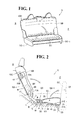
- FIG. 1 there are illustrated exemplary modes of automotive or vehicle seats, as generally designated by (S), in accordance with the present invention, but, it should be understood that all the modes include an interlocking means (M) in common, which are modified within the gist and scopes of the invention as will be described hereinafter.
- S exemplary modes of automotive or vehicle seats
- M interlocking means
- FIG. 1 there is illustrated a first embodiment of an automotive or vehicle seat as generally designated by (S).
- the illustrated seat is a rear bench-type seat comprising a seat back (SB) and a seat cushion (SC) .
- SB seat back
- SC seat cushion
- the seat cushion (SC) is, at its forward end, pivotally connected with a support bracket (23) by means of a hinge bracket (21), the support bracket (23) being fixed to a vehicle body (B), wherein one end of the hinge bracket (21) is pivotally connected by a second hinge pin (21B) with a frame (not shown) in the forward end of seat cushion (SC) , while another end of the hinge bracket (21) is pivotally connected by a first hinge pin (21A) with the support bracket (23) .
- the seat cushion (SC) which is now set in a horizontal use position, may be rotated or flipped over about the first hinge pin (21A) in a forward direction, i.e.
- both seat cushion (SC) and seat back (SB) may be rotated or flipped over in a backward direction, i.e. a direction toward a side (R) backwardly of the seat (S) .
- the wording "in the forward direction” or the wording “forwardly” shall refer to a direction toward the forward side of the seat (S) which is designated by (F), whereas the wording "in the backward direction” and the wording “backwardly” shall refer to a direction toward the backward side of the seat (S) which is designated by (R).
- the seat back (SB) is at its lower end portion pivotally connected via a pin (11A) to a support bracket (11) fixed on the vehicle body (B) .
- the seat back (SB) has a seat back frame (BF) provided therein and, strictly stated, a lower part of such seat back frame (BF) is pivotally connected via the pin (11A) to the support bracket (11) , so that the seat back frame (BF) (i.e. the seat back SB) can be rotated or folded down in the forward direction (at F) relative to the pin (11A) .
- the seat back (SB) may be locked and unlocked, at the upper back region thereof, to and from the vehicle body (B) by means of a lock mechanism (10) for the seat back (SB) .
- the seat back lock mechanism (10) is of a known structure comprising: a striker ( 10A) fixed to the vehicle body (B); a hook-like lock piece (10B) rotatably provided in the seat back (SB) so as to be engageable over the striker (10A); and an operation knob (10C) connected with the lock piece (10B).
- the lock piece (10B) is engaged over the striker (10A), thereby locking the seat back (SB) to the vehicle body (B) .
- the operation knob (10C) By drawing the operation knob (10C) outwardly, the lock piece (10B) is caused to rotate clockwise and thus disengaged from the striker (10A), so that the seat back (SB) is released from the locked state and may be folded down in the forward direction.
- a seat cushion frame is provided in the seat cushion (SC) as known.
- a pair of the hinge brackets (21) are fixed to the two lateral sides of such not-shown seat cushion frame in the seat cushion (SC), respectively, and that a pair of support brackets (23) are fixed on the vehicle body (B).
- Each hinge bracket (21) is rotatably connected, via a hinge pin (21A) , with each support bracket (23), thereby allowing the seat cushion (SC) to be rotated or flipped over about the hinge pin (21A) from the horizontal use position indicated by the solid lines to the upright storage position indicated by the two-dot chain lines, or vice versa.
- the interlocking means (M) is basically comprised of a elastically contractible/extendable biasing mechanism (ES), a link means (L), and a guide means (G).
- the elastically contractible/extendable biasing mechanism (ES) may be a pneumatic cylinder (4) (or a hydraulic cylinder).
- the pneumatic cylinder (4) comprises a cylindrical body portion (40) and a rod (41) movably provided in that body portion (40) such that the rod (41) is telescopically movable from and into the body portion (40) resiliently due to a compressed air pressure in the body portion (40) as is known in the art.
- the pneumatic cylinder (4) is also provided with a connecting bracket (43) at another end opposite to the rod (41), the connecting bracket (43) having a pair of connecting holes (43A) (43A) formed therein. As shown in Fig.
- the end connecting end portion (41E) of the rod (41) is pivotally connected with a bracket (24) fixed in the bottom side of seat cushion (SC).
- the elastically contractible/extendable mechanism (ES) is not limited to the pneumatic cylinder (4), but instead thereof, it may comprise a spring element of the type wherein a compression coil spring is wound about a rod portion.
- the link means (L) may comprise a link member (3) of generally "L" shape and a slide pin (6).
- the link member (3) is formed with a pair of connecting holes (31) (31) in the upper end (31E) thereof and also formed with a pair of elongated connecting holes (34) (34) in the lower end (34E) thereof.
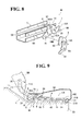
- the guide means (G) may comprise a guide rail member (5) of generally U-shaped cross-section having a horizontal bottom wall (52) and a pair of vertical walls (51) (51) extending upwardly therefrom.
- the guide rail member (5) is fixed, at the bottom wall (52) thereof, on the vehicle body (B) (or a floor of vehicle) , so as to extend longitudinally thereon.
- Each of the two vertical walls (51) of guide rail member (5) has a long guide slot (50) formed therein, the guide slot (50) extending along the longitudinal direction thereof.
- the slide pin (6) has a contact portion (60) and a slide portion (61) as shown in Fig. 7.
- the slide portion (61) of the slide pin (6) is adapted to be slidingly movable in and along the two guide holes (50) of the foregoing guide rail member (5).
- the contact portion (60) serves as a contact means adapted to contact and rotate a rotary actuator member (7) as will be explained.
- the slide portion (61) of slide pin (6) is inserted through one of the two guide slots (50) of the rail member (5), two connecting holes (43A) of the pneumatic cylinder (4), and two elongated connecting holes (34) of link member (3). Then, after having inserted the slide pin slide portion (61) through another of the two guide holes (50), the free end of that slide portion (60) is engaged with a nut or the like, or may be riveted, though not shown, whereupon all the pneumatic cylinder (4), link member (3) and guide rail member (5) are movably and operatively connected with one another via the slide pin (6).
- the whole of the pneumatic cylinder (4) extends alongside of the vertical wall (51) of the guide rail member (5) .
- the upper end portion (31E) of the link member (3) is pivotally connected with the seat back frame (BF) by inserting a pin (30) through the two connecting holes (31) and then fastening the pin (30) to the seat back frame (BF) , as can be seen from Figs. 2 and 7.
- Designation (35) denotes a spring adapted to prevent wobbling or rattling between the link member (3) and pneumatic cylinder (4) .
- the spring (35) is connected with a pin (35A) fixed in the link member (3) at one end thereof and also connected with the slide pin (6) at another end thereof so as to bias the lower end (34E) of link member (3) toward the connecting bracket (43) of the pneumatic cylinder (4) to biasingly bring one edge of each elongated connecting hole (34) to contact with the slide portion (61) of slide pin (6) , so that any play is eliminated between the elongated connecting hole (34) and the slide pin free end portion (61).
- the spring (35) is connected with a pin (35A) fixed in the link member (3) at one end thereof and also connected with the slide pin (6) at another end thereof so as to bias the lower end (34E) of link member (3) toward the connecting bracket (43) of the pneumatic cylinder (4) to biasingly bring one edge of each elongated connecting hole (34) to contact with the slide portion (61)
- a striker (20) is fixed to the inner surface of the upper seating side of the seat cushion (SC) and pendent therefrom.
- Designation (LM) represents a seat cushion lock mechanism provided in a locking/unlocking relation with the striker (20) to permit locking and unlocking the seat cushion (SC) to and from the vehicle body (B).
- the striker (20) is a part of the seat cushion lock mechanism (LM) .
- the seat cushion lock mechanism (LM) comprises: a base plate member (91); a support plate member (90); a rotary actuator member (7); and a rotary latch member (8).
- the base plate member (91) has, formed therein, a guide slot (96) which is identical in shape and size to the afore-stated guide slot (50) of the guide rail member (5), and a vertically extending cut-out portion (91A) adapted to allow ingress and egress of the foregoing striker (20) therethrough as will be explained.
- the base plate member (91) has a pair of connecting pins (99) (99) fixed at the respective two end portions thereof.
- the base plate member (91) is fixed to one vertical wall (51) of the guide rail member (5), with the guide slot (96) thereof in alignment with the guide slot (50) of the guide rail member (5).
- Designation (98) denotes an upwardly extending guide portion which simply serves to supportively contact and guide the cylindrical body portion (41) in vertical direction so that the cylindrical body portion (41) is prevented against dislocation in a direction transversely of the guide rail member (5).
- the support plate member (90) is of substantially “ " " shaped configuration, having a pair of connecting holes (99A) (99A) formed in the respective two end portions thereof and a pair of first and second support pins (93) (94) formed in the central body portion thereof.
- the support plate member (90) is formed with a vertically extending cut-out portion (90A) in the upper portion thereof, the cut-out portions (90A) being adapted to allow ingress and egress of the striker (20) therethrough as will be explained.
- the second support pin (94) is disposed below the cut-out portion (90A) to form a center of rotation for the rotary latch member (8) for a purpose to be set forth later.
- Designation (90B) denotes a lower flange portion formed in the lower end of the support plate member (90).
- the rotary actuator member (7) is so formed to have a cam portion (70) and a connecting portion (71) such that the cam and connecting portions (70) (71) are integrally connected together by a piece (72) and extend in a direction opposite to each other.
- the cam portion (70) has an edge that slopes upwardly in one direction (leftward) , in which edge, a first cam region (70A) is defined, and also has an edge that slopes upwardly in another opposite direction (rightward), in which edge, a second cam region (70B) is defined.
- a first cam region (70A) is defined
- a second cam region (70B) is defined.
- the connecting portion (71) has a connecting pin (78) formed in the free end portion thereof and a hole (93A) in the base end portion thereof, whereas the cam portion (70) has a hole (93A) formed in the base end portion thereof, such that those two holes (93A) are coaxially aligned with each other, through which two holes (93A), the first support pin (93) of support plate member (90) extends.
- the first support pin (93) is fixed at one end thereof to the support plate member (90), while being fixed at another end thereof to a bracket portion (92) of the support plate member (90), as can be seen from Figs. 4 and 7.
- the rotary actuator member (7) is rotatably supported by that first support pin (93). Further, as shown in Fig. 4, such rotary actuator member (7) is biasingly caused by a spring (74) to rotate in the anticlockwise direction.
- the rotary latch member (8) is of the illustrated configuration having, defined therein, a hook-like latch end portion (80), an elongated hole (8A), a hole (8B) and a stopper end portion (81).
- the rotary latch member (8) is rotatably supported at the hole (8B) thereof by the second support pin (94) of the support plate member (90), as in Fig.
- both cam and connecting portions (70) (71) are in the state of extending horizontally and rectilinearly along the longitudinal direction of the support plate member (90).
- the support plate member (90) which is thus provided with the rotary actuator member (7) and rotary latch member (8), is securely attached to the foregoing base plate member (91) by inserting and fixing (as by riveting) the two connecting pins (99) of the base plate member (91) in the respective two connecting holes (99A) of the support plate member (90), as understandable from Figs. 3 and 7.
- the seat cushion lock mechanism (LM) is securely attached to the lateral side (i.e. the vertical wall (51)) of the guide rail member (5).
- the whole heightwise-thickness of the seat cushion lock mechanism (LM) may be substantially equal to that of the guide rail member (5), thereby advantageously allowing the height of seat (S) to be reduced as required.
- stopper end portion (81) With regard to the stopper end portion (81), it is to be appreciated that, when the striker (20) is engaged with the rotary latch member (8), with the stopper end portion (81) of the latter in contact with the lower flange (90B), a great load applied to the seat cushion (SC) is transmitted through both striker (20) and latch member (8) and escaped through the stopper end portion (81) and both support and base plate members (90) (91) to the guide rail member (5) and thus to the vehicle body (B).
- a pair of the above-described interlocking means (M) and a pair of seat cushion lock mechanisms (LM) are provided to the respective two lateral sides of seat cushion (SB) .
- a pair of seat cushion side covers (SC-1) (SC-1) are attached to those two lateral sides of seat cushion (SB), respectively, so as to cover the respective pair of interlocking means (M) and seat cushion lock mechanism (LM ).
- the slide portion (61) of slide pin (6) is slidingly moved in and long the two guide slots (50) of the guide rail member (5) in the forward direction toward the first cam portion (70) of the rotary actuator member (7), while at the same time, the cylindrical body portion (40) is also moved forwardly along the rod portion (41).
- the rod portion (41) is shortened, because it enters the inside of the cylindrical body portion (40), thereby compressing an air therein, due to the fact that the seat back (SB) connected with that rod portion (41) is still in a locked relation with the lock mechanism (LM), with the striker (20) being engaged with the rotary latch member (8).
- LM locked relation with the lock mechanism
- the contact portion (60) of slide pin (6) is brought to contact with the first cam region (71A) of that first cam portion (70), and, with further forward movement of the slide pin contact portion (60), the rotary actuator member (7) is rotated about the first pin (93) in the clockwise arrow directions in Fig. 4, which in turn causes clockwise rotation of the connecting portion (71) of the rotary actuator member (7).
- the rotary latch member (8) connected via the pin (78) with the connecting portion (71), is rotated about the second pin (94) in the anticlockwise arrow direction, thereby being disengaged from the striker (20), so that the seat cushion (SB) is released from the locked state.
- the rod portion (41) rapidly projects and extends in the forward direction from the cylindrical body portion (40) under the outwardly expanding force of the compressed air.
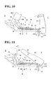
- such rapid forward projection of the rod portion (41) positively pushes the forward end portion (at 24) of the seat cushion (SC) which is pivotally connected with the end portion (41E) of the rod portion (41), whereupon the seat cushion (SC) is quickly rotated and flipped over forwardly relative to the pin (21A) to the upright storage position where it stands upright as shown in Fig. 10.
- the seat cushion lock mechanism (LM) should be arranged on the guide rail member (5) such that the slide pin contact portion (60) is to contact and push the cam portion (70) of actuator plate member (7) for disengagement of the latch plate member (8) from the striker (20) when the seat back (SB) is folded forwardly by a certain angle, so as to insure avoiding its contact with the seat cushion (SC) or avoids its interference with the foregoing flipping over of seat cushion (SC).
- FIG. 10 shows the seat back (SB) as being inclined forwardly by that certain angle, at which point, the slide pin contact portion (60) slides past the rotary actuator member cam portion (70), causing clockwise rotation of the same (70), whereupon the rotary latch member (8) is rotated and disengaged from the striker (20) and therefore the seat cushion (SC) is quickly flipped over to the upright storage position by the pneumatic cylinder (4) before contact with the seat back (SB) which is being folded down.
- the rod portion (41) of the pneumatic cylinder (4) stops there and is retained against forward movement.
- the cylinder portion (40) is moved forwardly along the rod portion (41).
- that particular rod portion (41) withdraws into the inside of the cylinder portion (40) and is shortened, so that the seat back (SB) is further rotated forwardly and folded down onto the area of vehicle body (B) or a horizontal storage position where the seat cushion (SB) has been set as its horizontal use position, as indicated by the two-dot chain line in Fig. 2.
- the back side (SB-1) of the thus-folded-down seat back (SB) is exposed outwardly and lies horizontally, thereby allowing its use as a flat floor or a load-carrying platform.
- a user when it is desired to return the thus-folded state of seat (S) into the previously described normal use state as in Fig. 2, a user has to first rotate the seat back (SB) upwardly about the pin (11A) as indicated by the arrow 1 ⁇ toward the upright use position. Responsive thereto, the link member (3) is simultaneously displaced in the upward direction indicated by the arrow 2 ⁇ , which in turn simultaneously causes the pneumatic cylinder (40) to move backwardly in the direction of the arrow 3 ⁇ , with the slide portion (61) of slide pin (6) moving in and along the guide slot (50).
- the seat back (SB) is firstly displaced out of the way of the seat cushion (SC), thus insuring that the seat cushion (SC) is secondly folded down without contact with the seat back (SB).
- the slide pin contact portion (60) is brought to contact with the second cam region (70B) of the rotary cam member (7), whereupon the rotary actuator member (7) is rotated clockwise (see the clockwise arrow in Fig. 11) to cause simultaneous anticlockwise rotation of the rotary latch member (8) (see the anticlockwise arrow in Fig. 11).
- the seat cushion lock mechanism (LM) is placed in an unlocked state where the hook-like latch portion (80) withdraws from a point corresponding to the two cut-out portions (90A) (91A), thereby providing an opened space therein.
- the striker (20) of the seat cushion (SC) is brought to such opened space and enters both two cut-out portions (90A) (91A) .
- the slide pin contact portion (60) contacts and slides past the first cam region (70A) , whereupon the rotary actuator member (7) is rotated anticlockwise under the biasing force of the spring (74) (see the anticlockwise arrow 1 ⁇ in Fig. 6) , while simultaneously, the rotary latch member (8) is rotated clockwise under the biasing force of the spring (82) (see the clockwise arrow 2 ⁇ in Fig. 7).
- the hook-like latch portion (80) of rotary latch member (8) is engaged with the striker (20) of the seat cushion (SC), while at the same time, the hook-like lock piece (10B) of the seat back (SB) is engaged over the striker (10A) fixed to the vehicle body (B).
- the seat back (SB) and seat cushion (SC) are respectively locked to their respective upright and horizontal use positions.
- a second embodiment of the present invention is basically identical in structure to the above-described firs embodiment, except that there is no lock mechanism equivalent to the seat cushion lock mechanism (LM) described in the first embodiment.
- the illustrated seat (S) is a rear bench-type seat comprising a seat back (SB) and a seat cushion (SC).
- the seat back (SB) and seat cushion (SC) are respectively provided with a seat back frame (12) and a seat cushion frame (22) therein.
- Fig. 13 the seat back (SB) and seat cushion (SC) are respectively provided with a seat back frame (12) and a seat cushion frame (22) therein.
- the seat cushion (SC) is, at its forward end, pivotally connected with a support bracket (23) by means of a hinge bracket (21), the support bracket (23) being fixed to a vehicle body (B), wherein one end of the hinge bracket (21) is fixed to the forward end of the seat cushion frame (22) and another end of the same (21) is pivotally connected by a hinge pin (21A) with the support bracket (23).
- the seat cushion (SC) may be rotated or flipped over relative to the hinge pin (21A) in the forward direction indicated by the arrow.
- the seat back (SB) is mounted on the vehicle body (B) so that the lower portion of the seat back may be rotated in the likewise forward direction (at F).
- both seat cushion (SC) and seat back (SB) may be rotated or flipped over in the backward direction.
- the seat back (SB) its seat back frame (12) is, at its lateral frame section (12L), pivotally connected via a pin (11A) with a support bracket (11) fixed on the vehicle body (B), so that the seat back frame (12) (i.e. the seat back SB) can be rotated or folded downwardly in the forward direction relative to the pin (11A).
- the seat back (SB) may be locked and unlocked, at the upper back region thereof, to and from the vehicle body (B) by means of a seat back lock mechanism (10).
- the seat back lock mechanism (10) is identical to the seat back mechanism (10) of the previously described first embodiment, and any further description is omitted thereon.
- a pair of the hinge brackets (21) are fixed to the two lateral sides of the seat cushion frame (22) and that a pair of the support brackets (23) are fixed on the vehicle body (B).
- Each of the hinge brackets (21) is rotatably connected, via a pin (11A), with each of the two support brackets (11), thereby allowing the seat cushion (SC) to be rotated or flipped over about the hinge pin (21A) from the horizontal normal use position indicated by the solid lines to the upright stored position indicated by the two-dot chain lines, or vice versa.
- the seat back frame (12) is, at the two lateral frame sections (12L) thereof, pivotally connected via two respective pins (11A) to the two support brackets (11), thereby allowing the seat back (SB) to be rotated or flipped over about the two hinge pins (11A) from the vertical use position indicated by the solid lines to the horizontal storage position indicated by the two-dot chain lines, or vice versa.
- the same interlocking means (M) as in the foregoing first embodiment is provided between the seat back (SB) and seat cushion (SC).
- the interlocking means (M) is basically comprised of an elastically contractible/extendable biasing means (ES), a link means (L), and a guide means (G).
- the elastically contractible/extendable biasing mechanism (ES) may be a pneumatic cylinder (4).
- the pneumatic cylinder (4) is not limitative, but such biassing mechanism (ES) may comprise a spring element of the type wherein a compression coil spring is wound about a rod portion.
- This pneumatic cylinder (4) is identical to the pneumatic cylinder (4) of the first embodiment, except that the end connecting end (41E) of rod portion (41) is pivotally connected via a bracket (42) with the forward frame section (22F) of seat cushion frame (22), as shown in Fig. 13.
- the link means (L) may comprise a link member (3) of generally "L" shape and a slide pin (6)
- the guide means (G) may comprise a guide rail member (5) of U-shaped cross-section.
- all the pneumatic cylinder (4), link member (3) and guide rail member (5) are movably and operatively connected with one another via the sliding pin (60), such that a whole of the link member (3) extends alongside of the vertical wall (51) of the guide rail member (5).
- the upper end portion of the link member (3) is pivotally connected with the lateral frame section (12L) by inserting a pin (30) through a connecting hole formed in that lateral frame section (12L) and the two connecting holes (31) (31 ) of the link member (3), as seen from Fig. 13.
- the coil spring (35) is connected with a pin (35A) fixed in the link member (3) at one end thereof and also connected with the slide pin (6) at another end thereof so as to bias the lower end of the link member (3) toward the connecting bracket (43) to cause one edge of each elongated connecting hole (34) to contact the slide pin (6) , so that any play is eliminated between the edge of connecting hole (34) and the slide pin (6) .
- the present interlocking means (M) there is no rattling and wabbling in the present interlocking means (M).
- a rotation center of the link member (3) is disposed above the pin (11A), i.e. a rotation center of the seat back (SB).
- the slide pin (6) is slidingly moved in and long the two guide slots (50) of the guide rail member (5) in the forward direction 3 ⁇ , while at the same time, the cylindrical body portion (40) is also moved forwardly along the rod portion (41).
- the rod portion (41) is shortened, because it enters the inside of the cylindrical body portion (40), thereby compressing an air therein.
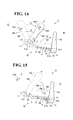
- the present embodiment is of such an arrangement that, prior to the seat back (SB) being rotated or inclined to a midway point (P) by the angle of ⁇ (about 45 degrees) from the use position indicated by the two-dot chain line, the seat cushion (SC) is completely flipped over from the horizontal use position indicated by the two-dot chain line to the upright storage position indicated by the solid line.
- the rod portion (41) is biasingly caused to extend forwardly from the cylindrical body portion (40) under the outwardly expanding force of the compressed air.
- the rod portion (41) of the pneumatic cylinder (4) stops there and is retained against forward movement.
- the cylinder portion (40) continues to move on forwardly along the rod portion (41).
- that particular rod portion (41) withdraws into the inside of cylinder portion (40) and is shortened, so that the seat back (SB) is further rotated forwardly and folded down to the horizontal storage position (i.e. the area where the seat cushion (SB) has been set), as indicated by the solid line in Fig. 15.
- the back side (SB-1) of the thus-folded-down seat back (SB) is exposed outwardly and lies horizontally, allowing its use as a flat floor or a load-carrying platform.
- the outwardly expanding force by compressed air in the pneumatic cylinder (4) not only biases the rod portion (41) in the forward direction, thereby positively preventing the seat cushion (SC) against backward inclination at the upright storage position, but also biases both cylinder body portion (40) and link member (3) in the backward direction to the pin (30), thereby positively preventing the seat back (SB) against backward rotation about the pin (11A) at the horizontal storage position.
- the pneumatic cylinder (4) per se serves as a lock means for locking the seat back (SB) and seat cushion (SC) to the horizontal and upright storage positions, respectively, as can be seen from Fig. 15.
- a user when it is desired to return the thus-folded state of seat (S) into the normal use state shown in Fig. 12, a user has to first rotate the seat back (SB) upwardly about the pin (11A) as indicated by the arrow 1 ⁇ in Fig. 16. Responsive thereto, the link member (3) is simultaneously displaced in the upward direction indicated by the arrow 2 ⁇ , which in turn simultaneously causes the pneumatic cylinder (40) to move backwardly in the direction of arrow 3 ⁇ , with the slide pin (6) moving in and along the guide slots (50) though not shown.
- the seat back (SB) is locked to the vehicle body (B) because the lock piece (10B) of the seat back lock mechanism (10) is engaged with the striker (10A).
- the seat cushion (SC) is also in a locked state to the vehicle body (B) because the link member (3) as well as the pneumatic cylinder (4) connected with that seat cushion (SC) are actually coupled with the thus-locked seat back (SB), thereby retaining the seat cushion (SC) against movement and rotation from the horizontal use position.
- Figs. 18 to 23 illustrates a third embodiment of the present invention as applied to the same fold-down seat (S) as having been described thus far. Hence, any further description is not made of the structure of seat (S) itself.
- the seat cushion (SC) may be rotated or flipped over relative to the hinge pin (21A) in the forward direction indicated by the arrow, and the seat back (SB) is mounted on the vehicle body (B) so that the lower portion of the seat back (SB) may be rotated in the likewise forward direction (at F).
- both seat cushion (SC) and seat back (SB) may be rotated or flipped over in the backward direction as indicated by the arrow.
- the interlocking means (M) is provided between the seat back (SB) and seat cushion (SC) to provide for the synchronized simultaneous flipping over of both of those seat back (SB) and seat cushion (SC) as described previously.
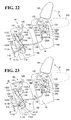
- the present third embodiment is directed to an interlocking arrangement between the headrest (HD) and the fold-down seat (S), using the common concept of interlocking means (M) within the gist and scopes of the present invention.
- the headrest (HR) is mounted on the top of the seat back (SB) so as to be movable or inclinable in the forward direction (i.e. to the side (F)) and in the backward direction (i.e. to the side (R)).
- a securing support element (120) is fixedly provided in the upper end portion of the seat back (SB).
- the securing support element (120) has, formed therein, a first support portion (120A), a second support portion (120B) and a third support portion (120C).
- the first and third support portions (120A) (120C) are disposed at a low level and at a high level, respectively, with the second support portion (120B) disposed at an intermediate level between the two support portions (120A) ( 120C).
- the headrest (HR) has a stay (130) whose end portion (130A) is fixed to a support pin (131) rotatably secured on the third support portion (120C) so that the headrest (HR) is rotated or inclined about that support pin (131) from the vertically extending use position indicated by the solid line to the forwardly inclined storage position indicated by the two-dot chain line, or vice versus.
- the seat cushion (SC) is opened in the bottom side thereof and hollow therein as indicated by (H). This hollow (H) serves as a storage space for allowing the forwardly inclined headrest (H) to be stored therein as will be explained later.
- a biasing spring (133) is connected between the stay end portion (130A) and the securing support element (120). Under the biasing force of that spring (133), the headrest (HD) is biasingly caused to rotate clockwise or in the forward direction as indicated by the two-dot chain line of Fig. 22.
- a headrest lock mechanism (200) for locking and unlocking the headrest (HD) to and from the vertically extending use position.
- the headrest lock mechanism (200) comprises: a hook-like latch member (121) rotatably provided on the second support portion (120B) of securing support element (120); and a lock piece (132) formed integrally with the end portion (130A) of headrest stay (130).
- the hook-like latch member (121) has one end in which an engagement notch (121A) is formed for engagement with the lock piece (132) and also has another end pivotally connected by a pin (121C) with the second support portion (120B).
- Designation (122) denotes a biasing spring which is at one end thereof connected with the hook-like latch member (121) and also connected with the securing support element (120) at another end thereof. Under the biasing force of such spring (122), the hook-like latch member (121) is biasingly caused to rotate about the pin (121C) in clockwise direction.
- the lock piece (132) is retained in engagement with the engagement notch (121A) of the hook-like latch member (121), as shown in Fig. 21, due to the above-described biasing effects of both two biasing springs (133) (122). Under that state, the headrest (HD) is locked to the generally upright use position, as in the Fig. 21.
- designation (100) represents a seat back lock mechanism for locking and unlocking the seat back (SB) to and from a striker (110) fixed to the vehicle body (B).
- the seat back lock mechanism (100) is comprised of: an operation lever (40); a lock bracket (112) connected via a connecting rod (114) with the operation lever (40); and a latch (111).
- the operation lever (40) is formed to have a knob portion (140) , an intermediate lever portion (141) and an actuator lever portion (142).
- the knob portion (140) is exposed outwardly from the seat back (SB) as can be seen from Figs. 1 and 21.
- the actuator lever portion (142) is rotatably secured by a pin (142A) to a first securing support plate (145) fixedly provided in the upper portion of the seat back (SB).
- the knob portion (140) is rotatable about the pin (142A) forwardly and backwardly. While not shown, there may be provided a biasing spring and a stopper in association with the operation lever (40).
- the biasing spring is connected between the actuator lever portion (142) and the securing support plate (145) so as to bias the actuator lever portion (142) in the anticlockwise direction and thereby retain the same in the normal inoperative position as in Fig. 21, where the actuator lever portion (142) is abutted against the stopper.
- a second securing support plate (115) is fixedly provided within the upper portion of seat back (SB) at a point lower than the foregoing first securing support plate (145).
- the second securing support plate (115) is disposed adjacent to the back side of seat back (SB) and has a horizontally extending elongated cut-out portion (115A) adapted for allowing ingress and egress of the striker (110) therethrough.
- the latch (111) is so formed to have: a lock engagement notch (111A); an engagement cut-out portion (111B); a protrudent portion (111D) defined between the lock engagement notch (111A) and engagement cut-out portion (111B); and a stopper edge portion (111F) contiguous with the engagement cut-out portion (111B).
- the lock engagement notch (111A) and engagement cut-out portion (111B) are defined in one end of the latch (111), whereas a spring securing piece (111E) is defined in another end of the latch (111).
- this latch (111) is rotatably supported substantially at its center by a support pin (111C) fixed to the securing support plate (115).
- the lock bracket (112) is formed with an engagement projection (112A) in the intermediate region thereof and also formed with an abutment edge portion (112D) . Both engagement projection (112A) and abutment edge portion (112D) in the aggregate correspond substantially in shape to a contour of the foregoing engagement cut-out portion (111B) of latch (111). Also, the lock bracket (112) is formed with a connecting pin (112C) in the free end portion thereof, the connecting pin (112C) projecting from both two sides of that free end portion of lock bracket (112) for a purpose to be set forth. As illustrated, this lock bracket (112) is rotatably supported, at the base end portion thereof, by a support pin (112B) fixed to the securing support plate (115).
- a spring (113) is connected between the spring securing pieces (111E) of latch (111) and the connecting pin (112C) of lock bracket (112), so that the lock bracket (112) is biasingly caused to rotate clockwise about the pin (112B), while simultaneously, the latch (111) is biasingly caused to rotate anticlockwise about the pin (111C), thereby normally retaining the engagement projection (112A) in engagement with the engagement cut-out portion (111B).
- one end of the connecting rod (114) is pivotally connected with a pin (144) fixed to the actuator lever portion (142) of operation lever (40) , while another end of the connecting rod (114) is pivotally connected with the connecting pin (112C) of lock bracket (112). It is seen that the pin (144) or the connection point of the connecting rod (114) is disposed near to the rotation center (at 142A) of the actuator lever portion (142).
- the interlocking means (M) is provided between the headrest lock mechanism (200) and the seat back lock mechanism (100).
- the interlocking means (M) may comprise a cable (124) and an extension region (142E) defined in the free end of the actuator lever portion (142) of operation lever (40). As shown, one end of the cable (124) is pivotally connected via a pin (143) with such extension region (142E) associated with the seat back lock mechanism (100). On the other hand, another end of the cable (124) is pivotally connected via a pin (121B) with the free end of the hook-like latch member (121) associated with the headrest lock mechanism (200) .
- the pin (143) or the connection point of the cable (124) is disposed a great distance from the rotation center (at 142A) of the actuator lever portion (142) in comparison with the connection point (at 144) of the connecting rod (114). Therefore, in view of a circle along which the connecting rod connection point (at 144) is to be moved about the rotation center (142A) and a circle along which the cable connection point (at 143) is to be moved about the rotation center (142A), it is to be seen that a radius between the cable connection point (at 143) and rotation center (142A) is larger than a radius between the connecting rod connection point (at 144) and rotation center (142A).
- the cable (124) moves an amount greater than the connecting rod (114), so that the headrest lock mechanism (200) connected with the cable (142) starts to be operated in advance before the seat back lock mechanism (100) connected with the connecting rod (114) is operated.
- the spring (113) is naturally stretched, but, at this point, the stretched spring (113) does not generate a contracting force enough to rotate the latch (111) anticlockwise, which means that there is no disengagement of the latch (111) form the striker (110) until the headrest (HD) reaches the non-use storage position indicated by the two-dot chain lines.
- the latch (111) per se is positively retained against rotation, such that the lock engagement notch (111A) thereof is kept positioned at a point away from the striker (110) as can be seen from Fig. 23. Further, under that state, the connecting rod (114) is positively prevented against movement
- the seat back (SB) is folded down, with the headrest (HD) set in the forwardly inclined storage position, in a direction to a horizontal non-use position, as indicated by the two-dot chain lines in Fig. 19.
- the seat cushion (SC) has been flipped over about the pin (21A) to the upright storage positions by means of the interlocking means (M) described in the first and second embodiment for instance.
- the headrest (HD) is stored in the hollow region (H) of the seat cushion (SC) set in the upright storage position.
- the seat back (SB) When it is desired to return the thus-folded-down seat (S) into the normal use state as in Fig. 18, the seat back (SB) is rotated from the horizontal non-use position indicated by the two-dot chain line to the vertically extending use position indicated solid line in Fig. 19.
- the operation knob (140) and latch (111) are retained in the unlocked state shown in Fig. 23, such that the former (140) is kept in the forwardly inclined state, while the lock engagement notch (111A) of the latter (111) is kept at a level below a line along which the striker (110) enters the back side of the seat back (SB) through the hole (SBh) adjacent to which the latch (111) is located.
- the striker (110) enters the inside of seat back (SB) as indicated by the two-dot chain arrow and collides against the protrudent portion (111D) of latch (111).
- the striker (110) enters the elongated cut-out portion (115A) of the second securing support plate (115) as indicated by the arrow 1 ⁇ and pushes the protrudent portion (111D) of latch (111).
- the latch (111) is thereby rotated about the pin (111C) in the clockwise arrow direction 2 ⁇ , while simultaneously, the striker (110) is engaged in the lock engagement notch (111A) as can be seen from Fig. 21.
- the lock bracket (112) is rotated about the pin (112B) clockwise, thereby bringing the engagement projection (112A) thereof to engagement with the engagement cut-out portion (111B) of latch (111), while at the same time, a contracting force increased in the spring (113) draws the connecting rod (114) via the lock bracket (112) in the downward direction.
- a contracting force increased in the spring (113) draws the connecting rod (114) via the lock bracket (112) in the downward direction.
- a user can rotate the headrest (HD) back to the vertically extending or upright use position (in the solid lines) from the forwardly inclined position (in the tow-dot chain lines) , as indicated by the arrow , bringing the lock piece (132) to engagement with the engagement notch (121A) of hook-like latch member (121), whereupon the headrest ( HD) is locked at the use position as shown in Fig. 19.
- the seat cushion (SC) may be automatically flipped over about the pin (21A) down to a horizontal use position as shown in Fig. 18, by means of the interlocking means (M) of the first and second embodiment.
- the two rear seats may be a second seat (FS) and a third seat (RS) in combination with a slide rail (203) by way of example.
- the second seat (FS) is of a fold-down type where its seat cushion (FC) can be flipped over to such upright non-use position as indicated by the two-dot chain lines.
- the slide rail (203) is of generally U-shaped cross-section having two vertical walls and two guide slots (230) (230) formed in the respective two vertical walls.
- the guide slots (230) form one element of the interlocking means (M) as will be explained later.
- the second seat (FS) comprises a seat cushion (FC) and a seat back (FB) pivotally connected with the seat cushion (FC) , wherein the seat cushion (FC) has a downwardly extending leg (251) fixed to the forward bottom region thereof and a downwardly extending striker (205) fixed to the backward bottom region thereof.
- the leg (251) is pivotally connected via a pin (252) with a support bracket (253) which is fixed on the floor (B) adjacent to the forward end of the long slide rail (203), so that the seat cushion (FC) of second seat (FS) can be rotated or flipped over forwardly and backwardly about the pin (252).
- the seat cushion (FC) is biased by a spring in a direction to the upright non-use position
- the seat back (FB) is provided with a lock mechanism and biased by a spring in a forward direction to the seat cushion (FC) in such a manner that, upon operation of the lock mechanism to an unlocking direction, the seat back (FB) is automatically folded by a biasing force of the spring onto the seat cushion (FC) .
- the third seat (RS) comprises a seat cushion (RC) and a seat back (RB).
- the seat cushion (RC) has, provided fixedly to the bottom thereof, a downwardly extending forward leg (204) and a downwardly extending backward leg (241).
- a slide pin (240) is fixed in the downward end portion of the forward leg (204) such that both two ends of the slide rod (240) project from the respective lateral sides of the forward leg (204).
- the slide pin (240) is slidably engaged in both two guide slots (230) of the long slide rail (203).
- the slide pin (240) form one element of the interlocking means (M) equivalent to the above-described slide rod (6) as will be explained later.
- the backward leg (241) also has a slide piece (241A) provided in the downward end thereof, the slide piece being slidably engaged in both of the two guide slots (230).
- the third seat (RS) is slidingly movable on and along the long slide rail (203) in either of forward direction (to the side (F)) and backward direction (to the side (R)).
- the present embodiment utilizes an interlocking means (M) and a seat cushion lock mechanism (LM), both of which are basically similar in structure to the interlocking means (M) and the seat lock mechanism (LM) described in the first and second embodiments.
- M interlocking means
- LM seat cushion lock mechanism
- the interlocking means (M) may comprise the guide slots (230) and the slide pin (240).
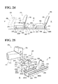
- the seat lock mechanism (LM) is provided laterally of the long slide rail (203) at a point right behind the second seat (RS) as shown in Fig. 24.
- the seat lock mechanism (LM) is comprised of a support bracket (206), a rotary actuator member (L1), and a rotary latch member (L2), wherein the rotary actuator member (L1) and rotary latch member (L2) are respectively similar in shape and structure to the afore-said rotary actuator member (7) and rotary latch member (8) of the first embodiment.
- the rotary actuator member (L1) is so formed to have a cam portion (210) and a connecting portion (211) such that the cam and connecting portions (210) (211) are integrally connected together by a piece (215) and extend horizontally in a direction opposite to each other.
- the cam portion (210) has an edge that slopes upwardly in one direction (rightward), in which edge, a first cam region (210A) is defined, and also has an edge that slopes upwardly in another opposite direction (leftward) , in which edge, a second cam region (210B) is defined.
- a first cam region 210A
- a second cam region 210B
- the connecting portion (211) has a connecting pin (213) formed in the free end portion thereof and a hole (216) formed in the base end portion thereof, whereas the cam portion (210) has a hole (216) formed in the base end portion thereof, such that those two holes (216) are coaxially aligned with each other.
- the rotary latch member (L2) is of the illustrated configuration having a hook-like latch end portion (221) defined in the free end thereof and a hole (226) formed in the base end thereof, with a vertically elongated hole (222) defined between the hook-like latch end portion (221) and the a hole (226).
- the support bracket (206) is formed by a vertically extending section (206A) and a horizontally extending section (206B). As shown in Fig. 25, the horizontally extending section (206B) is fixedly attached to one vertical lateral wall of the slide rail (203) , so that the support bracket (206) is disposed laterally of the slide rail (203).
- the vertically extending section (206A) has, formed therein, a vertically extending cut-out portion (206V), a first hole (206G) and a second hole (206H), wherein the first hole (206G) is disposed below the vertically extending cut-out portion (206V) and the second hole (206H) disposed above a line along which the guide slots (230) extend, as can be seen from Figs.
- a horizontally cut-out portion (206L) is formed in the horizontally extending section (206B) in communication with the vertically cut-out portion (206V).
- Those two cut-out portion (206V) (206L) are adapted to allow ingress and egress of the striker (205) of the second-seat seat cushion (FC) therethrough.
- a first pin (223) is inserted through the hole (226) of the rotary latch member (L2) and fixed in the first hole (206G), so that the rotary latch member (L2) is rotatably supported by the first pin (223) at a side laterally of the support bracket (206), whereas a second pin (212) is inserted through the two holes (216) of the rotary actuator member (L1) and fixed in the second hole (206H), so that the rotary actuator member (L1) is rotatably supported by the second pin (212) at a side laterally of the support bracket (206).
- the connecting pin (213) of the rotary actuator member (L1) is slidably inserted in the vertically elongated hole (213) of the rotary latch member (L2).
- the rotary latch member (L2) is biasingly caused by a spring (250) to rotate in the anticlockwise direction
- the rotary actuator member (L1) is biasingly caused by a spring (251) to rotate in the clockwise direction.
- the rotary latch member (L2) itself is normally held at the position where the hook-like latch end portion (221) is normally disposed at a point substantially corresponding to the cut-out portions (206V) (206L) for engagement with the striker (20) as will be explained.
- both cam and connecting portions (210) (211) of the rotary actuator member (L1) are in the state of extending horizontally and rectilinearly along the longitudinal direction of the support bracket (206) or the long slide rail (203).
- the whole height-wise thickness of the seat cushion lock mechanism (LM) is substantially equal to that of the long slide rail (203), thereby advantageously allowing the height of both two seats (FS) (RS) to be reduced as required and avoiding interference with the foots of passenger.
- Fig. 24 shows a normal seat use state where the second seat (FS) is locked to the long slide rail (203) or the vehicle floor (B) by means of the seat cushion lock mechanism (LM), and the third seat (RS) is position at a rearward point on the long slide rail (203).
- LM seat cushion lock mechanism
- the striker (205) is now out of engagement with the rotary latch member (L2).
- the second-seat seat cushion (FC) is automatically flipped over about the pin (252) by a spring (not shown).
- the striker (205) is moved upwardly away from the seat cushion lock mechanism (LM) with the flipping over of seat cushion (FC) or the second seat (FS) toward the generally upright non-use position as indicated in Fig. 24.
- the slide pin (240) moves past the lock mechanism (LM) forwardly along the guide slots (230) of long slide rail (203), thereby allowing the third seat (RS) to reach the forward end point of the long slide rail (203) where the first seat (FS) has been set.
- the rotary actuator and latch members (L1) (L2) are automatically returned to their horizontally extending and upright states, as in Fig. 26, under the biasing forces of the respective two springs (223) (251).
- the third seat (RS) reaches the foregoing forward end point of long slide rail (203), a widened space is obtained therebehind, which may be used as load-carrying platform or the like.
- the second seat (FS) is flipped over backwardly from the upright non-use storage state indicated by the two-dot chain line as in Fig. 24 down to the horizontal use position indicated by the solid line, so that the striker (205) enters the cut-out portions (206V) (206L).
- the slide pin (240) moves past the rotary actuator member (L1) backwardly, with the result that the rotary actuator member (L1) is automatically rotated clockwise under the biasing force of the spring (251).
- Such biased clockwise rotation of rotary actuator member (L1) and the biasing force of the spring (250) work together to cause the rotary latch member (L2) to rotate anticlockwise, thereby bringing the hook-like engagement portion (221) of rotary latch member (L2) to engagement with the striker (205).
- the second seat (FS) is locked to the long slide rail (203) or the floor (B), and then, the third seat (RS) may be moved on and along the long slide rail (203) to the normal position shown in Fig. 24.
- the third seat (RS) may be constructed in the same way as in the second seat (FS) and disposed at the forward position where the second seat (FS) is disposed, whereas the second seat (FS) be constructed in the same way as in the third seat (RS) and disposed at the backward position behind the thus-arranged third seat (RS).
- any other movable elements such as a first console box and a second console box, may be arranged on the long slide rail (203) via the interlocking means (M) and lock mechanism (LM).
- the first console box is pivotally disposed at the forward end portion of the long slide rail ( 203) so as to be able to be flipped over forwardly and be in operative connection with the lock mechanism (LM) as shown in Fig. 24, and that the second console box is slidably attached on the long slide rail (203), using the slide pin (240), at a point behind the first console box in the same manner as the third seat (RS).
- the second seat (FS) is automatically locked and unlocked to and from the use position by the forward and backward movement of the third seat (RS) under the action of the interlocking means (M), i.e. the combination of the slide pin (240) and the rotary actuator and latch members (L1 ) (L2).
- M interlocking means
Applications Claiming Priority (8)
| Application Number | Priority Date | Filing Date | Title |
|---|---|---|---|
| JP2002244779 | 2002-08-26 | ||
| JP2002247913 | 2002-08-26 | ||
| JP2002244769A JP3942084B2 (ja) | 2002-08-26 | 2002-08-26 | 車両用シート |
| JP2002244769 | 2002-08-26 | ||
| JP2002244773 | 2002-08-26 | ||
| JP2002244779A JP3783949B2 (ja) | 2002-08-26 | 2002-08-26 | ロック装置 |
| JP2002244773A JP3812742B2 (ja) | 2002-08-26 | 2002-08-26 | 前倒れシート |
| JP2002247913A JP3942085B2 (ja) | 2002-08-28 | 2002-08-28 | 車両用シート |
Publications (3)
| Publication Number | Publication Date |
|---|---|
| EP1393968A2 true EP1393968A2 (fr) | 2004-03-03 |
| EP1393968A3 EP1393968A3 (fr) | 2008-07-30 |
| EP1393968B1 EP1393968B1 (fr) | 2010-01-13 |
Family
ID=31499460
Family Applications (1)
| Application Number | Title | Priority Date | Filing Date |
|---|---|---|---|
| EP03255123A Expired - Fee Related EP1393968B1 (fr) | 2002-08-26 | 2003-08-19 | Siège de véhicule |
Country Status (3)
| Country | Link |
|---|---|
| US (1) | US6817646B2 (fr) |
| EP (1) | EP1393968B1 (fr) |
| DE (1) | DE60330938D1 (fr) |
Cited By (13)
| Publication number | Priority date | Publication date | Assignee | Title |
|---|---|---|---|---|
| FR2868997A1 (fr) * | 2004-04-15 | 2005-10-21 | Renault Sas | Siege arriere de vehicule automobile pourvu d'une cuvette anti-sousmarinage escamotable, et vehicule correspondant |
| FR2881693A1 (fr) * | 2005-02-10 | 2006-08-11 | Faurecia Sieges Automobile | Appuie-tete virgule, motorise, escamotable |
| ES2272139A1 (es) * | 2004-12-20 | 2007-04-16 | Viza Automocion, S.A.U. | Asiento abatible para vehiculos. |
| EP1810873A1 (fr) * | 2006-01-23 | 2007-07-25 | Viza Automocion, S.A.U. | Siège pliable pour véhicules |
| FR2909606A1 (fr) * | 2006-12-12 | 2008-06-13 | Renault Sas | Agencement de siege depliable, repliable et basculable pour vehicule automobile |
| FR2920711A1 (fr) * | 2007-09-07 | 2009-03-13 | Peugeot Citroen Automobiles Sa | Siege de vehicule automobile avec un dossier escamotable, ainsi que son procede d'escamotage et ses moyens de commande associes |
| WO2011063404A3 (fr) * | 2009-11-23 | 2011-08-25 | Weber Aircraft Llc | Ensemble de cuvette de siège |
| CN103282234A (zh) * | 2011-01-07 | 2013-09-04 | 提爱思科技股份有限公司 | 收纳式后座 |
| CN106314225A (zh) * | 2015-06-30 | 2017-01-11 | 长城汽车股份有限公司 | 车辆后排座椅翻折限位装置及车辆 |
| US20180079334A1 (en) * | 2016-09-20 | 2018-03-22 | Ford Global Technologies Llc | Vehicle seat assemblies |
| CN110267846A (zh) * | 2016-12-09 | 2019-09-20 | 布罗泽汽车部件制造科堡有限公司 | 具有在调节靠背时用于止动可至少部分降低的座垫承载件的止动机构的车辆座椅 |
| DE112005001056C5 (de) * | 2004-05-07 | 2020-03-19 | Fisher Dynamics Corp. | Motorbetriebene Fern-Freigabebetätigungsvorrichtung für eine Sitzanordnung |
| CN111071119A (zh) * | 2019-12-30 | 2020-04-28 | 郑州轻工业大学 | 一种汽车座椅减震垫 |
Families Citing this family (48)
| Publication number | Priority date | Publication date | Assignee | Title |
|---|---|---|---|---|
| FR2846919A1 (fr) * | 2002-11-07 | 2004-05-14 | Faurecia Sieges Automobile | Agencement de siege arriere de vehicule automobile comportant un dossier rabattable pourvu d'un appui-tete et vehicule comportant un tel siege |
| FR2856718B1 (fr) * | 2003-06-24 | 2005-09-09 | Faurecia Sieges Automobile | Systeme de verrouillage d'un premier element avec un deuxieme element et siege equipe d'un tel systeme de verrouillage |
| GB2407355B (en) * | 2003-10-22 | 2005-12-28 | Lear Corp | Hydraulic vehicle seat adjustment with system protection valve |
| WO2005044616A1 (fr) * | 2003-10-31 | 2005-05-19 | Johnson Controls Technology Company | Systeme de sieges de vehicule a position d'entree/sortie et a position de chargement sur le plancher |
| US7077463B2 (en) * | 2004-04-06 | 2006-07-18 | Lear Corporation | Rear fold down cargo seat with tilt down cushion |
| US20050242640A1 (en) * | 2004-04-15 | 2005-11-03 | Barko Jerry S | Folding headrest assembly |
| US7325877B2 (en) * | 2004-04-15 | 2008-02-05 | Windsor Machine & Stamping Limited | Foldable headrest assembly |
| JP2006006720A (ja) * | 2004-06-28 | 2006-01-12 | Aisin Seiki Co Ltd | 車両用シート格納装置 |
| GB2415618B (en) * | 2004-07-01 | 2006-09-20 | Lear Corp | Hydraulically powered folding vehicle seat fold |
| DE102005009182A1 (de) * | 2005-03-01 | 2006-09-07 | Daimlerchrysler Ag | Kraftfahrzeug |
| DE102005038802B4 (de) * | 2005-08-17 | 2008-05-08 | Faurecia Autositze Gmbh | Fondsitz |
| US7458609B2 (en) * | 2005-11-03 | 2008-12-02 | Ford Global Technologies, Llc | System and method for adjustably positioning a restraint system in a motor vehicle |
| US7717488B2 (en) * | 2005-12-19 | 2010-05-18 | Nissan Motor Co., Ltd. | Vehicle seat |
| US7597375B2 (en) * | 2006-01-23 | 2009-10-06 | Toyota Boshoku Kabushiki Kaisha | Vehicle seats |
| US7831379B2 (en) * | 2006-02-17 | 2010-11-09 | Lear Corporation | Roadside signage control from vehicle operating data |
| US20070194922A1 (en) * | 2006-02-17 | 2007-08-23 | Lear Corporation | Safe warn building system and method |
| US8000887B2 (en) * | 2006-02-17 | 2011-08-16 | Lear Corporation | Method and system of directing vehicles traveling over roadway during emergency |
| US7551068B2 (en) * | 2006-08-28 | 2009-06-23 | Lear Corporation | Vehicle seat alert system |
| DE102007022623B4 (de) * | 2007-05-15 | 2010-08-19 | Lear Corporation, Southfield | Fahrzeugsitz mit einer einstellbaren Kopfstütze |
| DE102007025318B3 (de) * | 2007-05-31 | 2009-01-22 | Lear Corp., Southfield | Fahrzeugsitz |
| DE102008006414B3 (de) * | 2007-10-02 | 2009-03-12 | Johnson Controls Gmbh | Fahrzeugsitz |
| US7819479B2 (en) * | 2007-10-10 | 2010-10-26 | Lear Corporation | Vehicle seat assembly having walk-in and fold-flat features |
| WO2011002027A1 (fr) | 2009-07-03 | 2011-01-06 | テイ・エス テック株式会社 | Siège pour le transport |
| JP4785011B2 (ja) * | 2009-08-21 | 2011-10-05 | トヨタ紡織株式会社 | 車両用シート |
| KR101209993B1 (ko) * | 2010-12-03 | 2012-12-07 | 현대자동차주식회사 | 자동차용 시트의 폴드 앤 다이브 구조 |
| US8783753B2 (en) | 2011-01-07 | 2014-07-22 | Ts Tech Co., Ltd. | Stowable rear seat |
| US20120251282A1 (en) * | 2011-04-04 | 2012-10-04 | Selvarajpandian Ramkumar | Debris kit for hydraulic cylinder |
| US8955913B2 (en) * | 2011-05-05 | 2015-02-17 | Lear Corporation | Retracting and folding vehicle head restraint |
| ITMI20120151U1 (it) * | 2012-04-13 | 2013-10-14 | Piaggio & C Spa | Assieme costituito da una sella e da un vano sottosella per motocicli |
| CN102632812B (zh) * | 2012-04-28 | 2013-08-21 | 长城汽车股份有限公司 | 汽车可折叠座椅解锁限位机构 |
| JP6057065B2 (ja) * | 2012-11-19 | 2017-01-11 | スズキ株式会社 | 車両用シートのシートバックのロック構造 |
| CN203592909U (zh) * | 2013-11-18 | 2014-05-14 | 福特环球技术公司 | 车辆座椅靠背的固定总成、车辆 |
| DE102014206849A1 (de) * | 2013-12-04 | 2015-06-11 | Johnson Controls Components Gmbh & Co. Kg | Fahrzeugsitz und Verfahren zum Fixieren eines Sitzelements |
| CN103625311B (zh) * | 2013-12-05 | 2016-06-22 | 上海延锋江森座椅有限公司 | 一种汽车座椅靠背挂钩锁止结构 |
| DE102014209168B4 (de) * | 2014-01-20 | 2021-03-25 | Adient Luxembourg Holding S.À R.L. | Fahrzeugsitz |
| DE102014209167A1 (de) * | 2014-01-20 | 2015-08-06 | Johnson Controls Components Gmbh & Co. Kg | Fahrzeugsitz und Verfahren zur Einstellung einer Ladestellung |
| JP6401383B2 (ja) * | 2015-04-23 | 2018-10-10 | 株式会社タチエス | 車両用シート |
| US10640013B2 (en) * | 2015-04-23 | 2020-05-05 | Tachi-S Co., Ltd. | Seat for vehicles |
| US9944204B2 (en) * | 2016-01-07 | 2018-04-17 | Toyota Motor Engineering & Manufacturing North America, Inc. | Rear seat having two independent modes |
| WO2018016137A1 (fr) * | 2016-07-20 | 2018-01-25 | 株式会社タチエス | Siège de véhicule |
| US10344796B2 (en) * | 2017-03-17 | 2019-07-09 | Ford Global Technologies, Llc | Retention mechanism for a forward folding seat assembly |
| US10308146B1 (en) | 2018-01-25 | 2019-06-04 | Ford Global Technologies, Llc | Track release mechanism for a seating assembly |
| US10647236B2 (en) | 2018-01-25 | 2020-05-12 | Ford Global Technologies, Llc | Dual cam latch |
| CN109703425A (zh) * | 2018-07-03 | 2019-05-03 | 上海国琻汽车科技有限公司 | 防翻转座椅骨架及包含其的汽车座椅 |
| US11180256B2 (en) | 2018-12-18 | 2021-11-23 | The Boeing Company | Transformable seat assembly |
| US11352143B2 (en) * | 2018-12-18 | 2022-06-07 | The Boeing Company | Transformable seat assembly |
| DE102020106027A1 (de) | 2020-03-05 | 2021-09-09 | Zim Flugsitz Gmbh | Fluggastsitz mit Umhausung |
| KR20220102731A (ko) * | 2021-01-14 | 2022-07-21 | 현대자동차주식회사 | 자동차용 시트의 피로저감 자세 구현장치 |
Citations (2)
| Publication number | Priority date | Publication date | Assignee | Title |
|---|---|---|---|---|
| JPS54129620A (en) | 1978-03-20 | 1979-10-08 | Peugeot | Convertible seat structure for automobile |
| JPS6458330A (en) | 1987-08-31 | 1989-03-06 | Mitsui Mining Co Ltd | Denitration method by impregnated carbon material |
Family Cites Families (28)
| Publication number | Priority date | Publication date | Assignee | Title |
|---|---|---|---|---|
| FR2471162A1 (fr) * | 1979-12-12 | 1981-06-19 | Renault | Siege rabattable perfectionne, notamment pour vehicule automobile |
| FR2483339A1 (fr) * | 1980-06-03 | 1981-12-04 | Renault | Siege transformable pour vehicule automobile avec assise relevable et dossier rabattable a mouvements simultanes |
| DE3206293A1 (de) * | 1982-02-22 | 1983-09-01 | P.A. Rentrop, Hubbert & Wagner Fahrzeugausstattungen GmbH &Co KG, 3060 Stadthagen | Kraftfahrzeug-ruecksitz |
| JPS63121143A (ja) | 1986-11-11 | 1988-05-25 | Canon Inc | 光カ−ドおよびその製造方法 |
| JPH07106166B2 (ja) * | 1990-08-22 | 1995-11-15 | タカラベルモント株式会社 | 椅子のシートチルト装置 |
| JPH0545544A (ja) | 1991-07-19 | 1993-02-23 | Victor Co Of Japan Ltd | 光導波路 |
| DE4136363C2 (de) * | 1991-11-05 | 1995-08-31 | Audi Ag | Rücksitz für Kraftfahrzeuge |
| US5954398A (en) * | 1996-03-14 | 1999-09-21 | Mitsubishi Jidosha Kogyo Kabushiki Kaisha | Seat structure for motor vehicle |
| US5626391A (en) * | 1995-05-25 | 1997-05-06 | Bertrand Faure Ltd. | Uptiltable rear vehicle seat assembly |
| JP3292626B2 (ja) * | 1995-06-22 | 2002-06-17 | アイシン精機株式会社 | 車両用シート |
| DE69616477T2 (de) * | 1995-09-22 | 2002-05-16 | Toyota Motor Co Ltd | Rücksitz für Fahrzeuge |
| JP2977472B2 (ja) * | 1995-10-06 | 1999-11-15 | 本田技研工業株式会社 | 車両用シートのヘッドレスト収納機構 |
| US5641202A (en) * | 1996-01-16 | 1997-06-24 | Lear Seating Corporation | Release latch for utility seat |
| US5671948A (en) * | 1996-04-10 | 1997-09-30 | Lear Corporation | Seat and seat belt restraint assembly |
| US5738411A (en) * | 1997-01-23 | 1998-04-14 | Hoover Universal, Inc. | Vehicle seat assembly |
| US5826942A (en) * | 1997-01-23 | 1998-10-27 | Hoover Universal, Inc. | Vehicle seat assembly with adjustable headrest coupled to seat back latch |
| US6279982B1 (en) * | 1998-05-13 | 2001-08-28 | Toyota Jidosha Kabushiki Kaisha | Vehicle seat storing device |
| US6010190A (en) * | 1998-05-29 | 2000-01-04 | Meritor Automotive Canada, Inc. | Seat track with cam actuated locking device and bypass assembly |
| US6059345A (en) * | 1998-06-18 | 2000-05-09 | Tachi-S Co., Ltd. | Slide rail device for vehicle seat |
| DE19837838C1 (de) * | 1998-08-20 | 1999-11-18 | Daimler Chrysler Ag | Rücksitzanordnung für Fahrgastzellen |
| US6113191A (en) * | 1998-10-21 | 2000-09-05 | Johnson Controls Technology Company | Storable seat assembly |
| US6371558B1 (en) * | 1999-10-14 | 2002-04-16 | Bertrand Faure Components Ltd. | Fold flat vehicle seat |
| US6174017B1 (en) * | 1999-11-04 | 2001-01-16 | Daimlerchrysler Corporation | Dumping and articulating seat |
| JP2002104029A (ja) * | 2000-09-27 | 2002-04-09 | Fuji Kiko Co Ltd | 車両用シートのクッション跳ね上げ装置 |
| US6688666B2 (en) * | 2001-09-13 | 2004-02-10 | Colin G. Neale | Second row fold and pivot seat assembly |
| US6676216B1 (en) * | 2002-03-22 | 2004-01-13 | Lear Corporation | Vehicle seat assembly |
| US6746083B2 (en) * | 2002-09-27 | 2004-06-08 | Lear Corporation | Vehicle seat assembly |
| US6648393B1 (en) * | 2002-12-17 | 2003-11-18 | General Motors Corporation | Lateral sliding seat |
-
2003
- 2003-08-12 US US10/638,472 patent/US6817646B2/en not_active Expired - Fee Related
- 2003-08-19 EP EP03255123A patent/EP1393968B1/fr not_active Expired - Fee Related
- 2003-08-19 DE DE60330938T patent/DE60330938D1/de not_active Expired - Lifetime
Patent Citations (2)
| Publication number | Priority date | Publication date | Assignee | Title |
|---|---|---|---|---|
| JPS54129620A (en) | 1978-03-20 | 1979-10-08 | Peugeot | Convertible seat structure for automobile |
| JPS6458330A (en) | 1987-08-31 | 1989-03-06 | Mitsui Mining Co Ltd | Denitration method by impregnated carbon material |
Cited By (19)
| Publication number | Priority date | Publication date | Assignee | Title |
|---|---|---|---|---|
| WO2005102772A3 (fr) * | 2004-04-15 | 2006-01-12 | Renault Sa | Siege arriere de vehicule automobile pourvu d'une cuvette anti-sousmarinage escamotable, et vehicule correspondant. |
| FR2868997A1 (fr) * | 2004-04-15 | 2005-10-21 | Renault Sas | Siege arriere de vehicule automobile pourvu d'une cuvette anti-sousmarinage escamotable, et vehicule correspondant |
| DE112005001056C5 (de) * | 2004-05-07 | 2020-03-19 | Fisher Dynamics Corp. | Motorbetriebene Fern-Freigabebetätigungsvorrichtung für eine Sitzanordnung |
| ES2272139A1 (es) * | 2004-12-20 | 2007-04-16 | Viza Automocion, S.A.U. | Asiento abatible para vehiculos. |
| FR2881693A1 (fr) * | 2005-02-10 | 2006-08-11 | Faurecia Sieges Automobile | Appuie-tete virgule, motorise, escamotable |
| EP1810873A1 (fr) * | 2006-01-23 | 2007-07-25 | Viza Automocion, S.A.U. | Siège pliable pour véhicules |
| FR2909606A1 (fr) * | 2006-12-12 | 2008-06-13 | Renault Sas | Agencement de siege depliable, repliable et basculable pour vehicule automobile |
| FR2920711A1 (fr) * | 2007-09-07 | 2009-03-13 | Peugeot Citroen Automobiles Sa | Siege de vehicule automobile avec un dossier escamotable, ainsi que son procede d'escamotage et ses moyens de commande associes |
| WO2011063404A3 (fr) * | 2009-11-23 | 2011-08-25 | Weber Aircraft Llc | Ensemble de cuvette de siège |
| US8616631B2 (en) | 2009-11-23 | 2013-12-31 | Zodiac Seats Us Llc | Seat pan assembly |
| CN103282234A (zh) * | 2011-01-07 | 2013-09-04 | 提爱思科技股份有限公司 | 收纳式后座 |
| US9126503B2 (en) | 2011-01-07 | 2015-09-08 | Ts Tech Co., Ltd. | Stowable rear seat |
| CN106314225A (zh) * | 2015-06-30 | 2017-01-11 | 长城汽车股份有限公司 | 车辆后排座椅翻折限位装置及车辆 |
| CN106314225B (zh) * | 2015-06-30 | 2018-11-13 | 长城汽车股份有限公司 | 车辆后排座椅翻折限位装置及车辆 |
| US20180079334A1 (en) * | 2016-09-20 | 2018-03-22 | Ford Global Technologies Llc | Vehicle seat assemblies |
| US10421382B2 (en) * | 2016-09-20 | 2019-09-24 | Ford Global Technologies Llc | Vehicle seat assemblies |
| CN110267846A (zh) * | 2016-12-09 | 2019-09-20 | 布罗泽汽车部件制造科堡有限公司 | 具有在调节靠背时用于止动可至少部分降低的座垫承载件的止动机构的车辆座椅 |
| CN111071119A (zh) * | 2019-12-30 | 2020-04-28 | 郑州轻工业大学 | 一种汽车座椅减震垫 |
| CN111071119B (zh) * | 2019-12-30 | 2021-10-08 | 郑州轻工业大学 | 一种汽车座椅减震垫 |
Also Published As
| Publication number | Publication date |
|---|---|
| US6817646B2 (en) | 2004-11-16 |
| US20040104590A1 (en) | 2004-06-03 |
| EP1393968B1 (fr) | 2010-01-13 |
| EP1393968A3 (fr) | 2008-07-30 |
| DE60330938D1 (de) | 2010-03-04 |
Similar Documents
| Publication | Publication Date | Title |
|---|---|---|
| EP1393968A2 (fr) | Siège de véhicule | |
| US6695405B2 (en) | Seat device including a fold-down back | |
| CA2448588C (fr) | Siege a bonne accessibilite avec verrou de plancher solidaire du dossier | |
| US7967375B2 (en) | Headrest apparatus moveable in cooperation with seat back | |
| JP5125617B2 (ja) | 乗物用シート | |
| CA2191545C (fr) | Mecanisme de verrouillage de securite pour siege coulissant de vehicule automobile | |
| KR101418132B1 (ko) | 리트랙터블 후방 레그를 갖는 스탠드 업 좌석 조립체 | |
| US6688666B2 (en) | Second row fold and pivot seat assembly | |
| JP2004249109A (ja) | 折り畳みシートおよびこのようなシートを含む乗物 | |
| CA2577618A1 (fr) | Mecanisme de liberation de rails de fixation de siege a acces facile | |
| US7159922B2 (en) | Seat structure for vehicle | |
| JP5109543B2 (ja) | 乗物用シート | |
| JPH10297332A (ja) | 車両用座席 | |
| EP0889799B1 (fr) | Siège basculant avec libération par poignée latérale deplaçable | |
| JP2004513820A (ja) | 自動車シート | |
| JP4235967B2 (ja) | 跳上げ可能なスライド式折畳み自在シート | |
| JP3942084B2 (ja) | 車両用シート | |
| KR20070031493A (ko) | 더블 폴딩 시트용 폴딩 위치 제한장치 | |
| JP4150607B2 (ja) | シートのウォークインキャンセル装置 | |
| JPH0322336B2 (fr) | ||
| GB2255903A (en) | Locking and release mechanism for slidable vehicle seat | |
| CN111954608A (zh) | 具有互锁的内部完全记忆座椅轨道 | |
| JPS6135013B2 (fr) | ||
| KR20150063694A (ko) | 차량용 시트의 워크인 메모리 장치 | |
| KR102623415B1 (ko) | 차량용 시트백 구속장치 |
Legal Events
| Date | Code | Title | Description |
|---|---|---|---|
| PUAI | Public reference made under article 153(3) epc to a published international application that has entered the european phase |
Free format text: ORIGINAL CODE: 0009012 |
|
| AK | Designated contracting states |
Kind code of ref document: A2 Designated state(s): AT BE BG CH CY CZ DE DK EE ES FI FR GB GR HU IE IT LI LU MC NL PT RO SE SI SK TR |
|
| AX | Request for extension of the european patent |
Extension state: AL LT LV MK |
|
| 17P | Request for examination filed |
Effective date: 20050103 |
|
| PUAL | Search report despatched |
Free format text: ORIGINAL CODE: 0009013 |
|
| AK | Designated contracting states |
Kind code of ref document: A3 Designated state(s): AT BE BG CH CY CZ DE DK EE ES FI FR GB GR HU IE IT LI LU MC NL PT RO SE SI SK TR |
|
| AX | Request for extension of the european patent |
Extension state: AL LT LV MK |
|
| AKX | Designation fees paid |
Designated state(s): DE FR GB |
|
| 17Q | First examination report despatched |
Effective date: 20090317 |
|
| GRAP | Despatch of communication of intention to grant a patent |
Free format text: ORIGINAL CODE: EPIDOSNIGR1 |
|
| GRAS | Grant fee paid |
Free format text: ORIGINAL CODE: EPIDOSNIGR3 |
|
| GRAA | (expected) grant |
Free format text: ORIGINAL CODE: 0009210 |
|
| AK | Designated contracting states |
Kind code of ref document: B1 Designated state(s): DE FR GB |
|
| REG | Reference to a national code |
Ref country code: GB Ref legal event code: FG4D |
|
| REF | Corresponds to: |
Ref document number: 60330938 Country of ref document: DE Date of ref document: 20100304 Kind code of ref document: P |
|
| PLBE | No opposition filed within time limit |
Free format text: ORIGINAL CODE: 0009261 |
|
| STAA | Information on the status of an ep patent application or granted ep patent |
Free format text: STATUS: NO OPPOSITION FILED WITHIN TIME LIMIT |
|
| 26N | No opposition filed |
Effective date: 20101014 |
|
| PGFP | Annual fee paid to national office [announced via postgrant information from national office to epo] |
Ref country code: GB Payment date: 20110816 Year of fee payment: 9 Ref country code: FR Payment date: 20110901 Year of fee payment: 9 |
|
| GBPC | Gb: european patent ceased through non-payment of renewal fee |
Effective date: 20120819 |
|
| REG | Reference to a national code |
Ref country code: FR Ref legal event code: ST Effective date: 20130430 |
|
| PG25 | Lapsed in a contracting state [announced via postgrant information from national office to epo] |
Ref country code: GB Free format text: LAPSE BECAUSE OF NON-PAYMENT OF DUE FEES Effective date: 20120819 |
|
| PG25 | Lapsed in a contracting state [announced via postgrant information from national office to epo] |
Ref country code: FR Free format text: LAPSE BECAUSE OF NON-PAYMENT OF DUE FEES Effective date: 20120831 |
|
| PGFP | Annual fee paid to national office [announced via postgrant information from national office to epo] |
Ref country code: DE Payment date: 20150811 Year of fee payment: 13 |
|
| REG | Reference to a national code |
Ref country code: DE Ref legal event code: R119 Ref document number: 60330938 Country of ref document: DE |
|
| PG25 | Lapsed in a contracting state [announced via postgrant information from national office to epo] |
Ref country code: DE Free format text: LAPSE BECAUSE OF NON-PAYMENT OF DUE FEES Effective date: 20170301 |