EP1382850B1 - Hermetischer Verdichter - Google Patents
Hermetischer Verdichter Download PDFInfo
- Publication number
- EP1382850B1 EP1382850B1 EP03011282A EP03011282A EP1382850B1 EP 1382850 B1 EP1382850 B1 EP 1382850B1 EP 03011282 A EP03011282 A EP 03011282A EP 03011282 A EP03011282 A EP 03011282A EP 1382850 B1 EP1382850 B1 EP 1382850B1
- Authority
- EP
- European Patent Office
- Prior art keywords
- feed pipe
- oil feed
- crankshaft
- driven compressor
- oil
- Prior art date
- Legal status (The legal status is an assumption and is not a legal conclusion. Google has not performed a legal analysis and makes no representation as to the accuracy of the status listed.)
- Expired - Lifetime
Links
- 239000003921 oil Substances 0.000 claims description 59
- 239000010721 machine oil Substances 0.000 claims description 20
- 230000006835 compression Effects 0.000 claims description 14
- 238000007906 compression Methods 0.000 claims description 14
- 238000005086 pumping Methods 0.000 claims description 9
- 229920003002 synthetic resin Polymers 0.000 claims description 5
- 239000000057 synthetic resin Substances 0.000 claims description 5
- 230000002708 enhancing effect Effects 0.000 claims 1
- 238000003756 stirring Methods 0.000 description 5
- 239000003507 refrigerant Substances 0.000 description 3
- TXEYQDLBPFQVAA-UHFFFAOYSA-N tetrafluoromethane Chemical compound FC(F)(F)F TXEYQDLBPFQVAA-UHFFFAOYSA-N 0.000 description 2
- 230000015572 biosynthetic process Effects 0.000 description 1
- 230000003247 decreasing effect Effects 0.000 description 1
- 230000001419 dependent effect Effects 0.000 description 1
- 230000006870 function Effects 0.000 description 1
- 238000005461 lubrication Methods 0.000 description 1
- 239000000463 material Substances 0.000 description 1
Images


Classifications
-
- F—MECHANICAL ENGINEERING; LIGHTING; HEATING; WEAPONS; BLASTING
- F04—POSITIVE - DISPLACEMENT MACHINES FOR LIQUIDS; PUMPS FOR LIQUIDS OR ELASTIC FLUIDS
- F04B—POSITIVE-DISPLACEMENT MACHINES FOR LIQUIDS; PUMPS
- F04B39/00—Component parts, details, or accessories, of pumps or pumping systems specially adapted for elastic fluids, not otherwise provided for in, or of interest apart from, groups F04B25/00 - F04B37/00
- F04B39/02—Lubrication
-
- F—MECHANICAL ENGINEERING; LIGHTING; HEATING; WEAPONS; BLASTING
- F04—POSITIVE - DISPLACEMENT MACHINES FOR LIQUIDS; PUMPS FOR LIQUIDS OR ELASTIC FLUIDS
- F04B—POSITIVE-DISPLACEMENT MACHINES FOR LIQUIDS; PUMPS
- F04B39/00—Component parts, details, or accessories, of pumps or pumping systems specially adapted for elastic fluids, not otherwise provided for in, or of interest apart from, groups F04B25/00 - F04B37/00
- F04B39/0094—Component parts, details, or accessories, of pumps or pumping systems specially adapted for elastic fluids, not otherwise provided for in, or of interest apart from, groups F04B25/00 - F04B37/00 crankshaft
-
- F—MECHANICAL ENGINEERING; LIGHTING; HEATING; WEAPONS; BLASTING
- F04—POSITIVE - DISPLACEMENT MACHINES FOR LIQUIDS; PUMPS FOR LIQUIDS OR ELASTIC FLUIDS
- F04B—POSITIVE-DISPLACEMENT MACHINES FOR LIQUIDS; PUMPS
- F04B39/00—Component parts, details, or accessories, of pumps or pumping systems specially adapted for elastic fluids, not otherwise provided for in, or of interest apart from, groups F04B25/00 - F04B37/00
- F04B39/0027—Pulsation and noise damping means
-
- F—MECHANICAL ENGINEERING; LIGHTING; HEATING; WEAPONS; BLASTING
- F04—POSITIVE - DISPLACEMENT MACHINES FOR LIQUIDS; PUMPS FOR LIQUIDS OR ELASTIC FLUIDS
- F04B—POSITIVE-DISPLACEMENT MACHINES FOR LIQUIDS; PUMPS
- F04B39/00—Component parts, details, or accessories, of pumps or pumping systems specially adapted for elastic fluids, not otherwise provided for in, or of interest apart from, groups F04B25/00 - F04B37/00
- F04B39/02—Lubrication
- F04B39/0223—Lubrication characterised by the compressor type
- F04B39/023—Hermetic compressors
- F04B39/0238—Hermetic compressors with oil distribution channels
- F04B39/0246—Hermetic compressors with oil distribution channels in the rotating shaft
- F04B39/0253—Hermetic compressors with oil distribution channels in the rotating shaft using centrifugal force for transporting the oil
-
- F—MECHANICAL ENGINEERING; LIGHTING; HEATING; WEAPONS; BLASTING
- F04—POSITIVE - DISPLACEMENT MACHINES FOR LIQUIDS; PUMPS FOR LIQUIDS OR ELASTIC FLUIDS
- F04C—ROTARY-PISTON, OR OSCILLATING-PISTON, POSITIVE-DISPLACEMENT MACHINES FOR LIQUIDS; ROTARY-PISTON, OR OSCILLATING-PISTON, POSITIVE-DISPLACEMENT PUMPS
- F04C29/00—Component parts, details or accessories of pumps or pumping installations, not provided for in groups F04C18/00 - F04C28/00
- F04C29/02—Lubrication; Lubricant separation
- F04C29/028—Means for improving or restricting lubricant flow
Definitions
- the present invention relates to an hermetic motor-driven compressor for use in refrigerators, freezers and other low-temperature appliances.
- JP 8-144950 A discloses hermetic motor-driven compressors.
- An example of such conventional hermetic motor-driven compressors is disclosed in Fig. 1 .
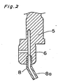
- Fig. 2 shows a principal portion of a crankshaft of the conventional hermetic motor-driven compressor.
- the hermetic motor-driven compressor includes a compression component 2 and a motor drive component 3 in a hermetically sealed enclosure 1, in which refrigerating machine oil 4 held in bottom of the hermetically sealed enclosure 1.
- Refrigerant 14 is filled up a space within the hermetically sealed enclosure 1.
- crankshaft 5 connected rotatably to the motor-driven component 3 is supported by a bearing 7 and is provided with an eccentric portion 6.
- An oil feed pipe 8 fixedly is secured to the eccentric portion 6 while the leading end of the oil feed pipe is opened in the refrigerating machine oil 4.
- the eccentric portion 6 is connected to a connecting rod 9 which is connected a piston 10 of the compression portion with a piston pin 11 to compress the refrigerant.
- torque of the motor drive component 3 is converted to reciprocating movement through the eccentric portion 3 and the connecting rod 9 so as to perform compression by the piston 10 in the compression component 2.
- crankshaft 5 is rotatively driven by the motor drive component 3 to rotate the oil feed pipe 8 with its centrifugal pumping portion 8a dipped in the refrigerating machine oil 4 held within the hermetically sealed enclosure 1 to produce an oil pressure inside of the oil feed pipe 8, so that the refrigerating machine oil 4 can be sucked up by the oil feed pipe 8 and then supplied to every sliding portion in the compressor.
- the refrigerant 14 which has dissolved in the refrigerating machine oil 4 forms bubbles, which shake the rotating oil feed pipe 8 to generate the resonance sound.
- the resonance sound of the pipe 8 increases noises in the hermetic motor-driven compressor together with the oil surface cutting sound produced by the oil feed pipe 8 cutting into the oil surface and the colliding sounds produced by droplets, spattered from the refrigerating machine oil 4 stirred vigorously by the oil feed pipe 8, clashing against the oil surface, the inside wall of the hermetically.sealed enclosure, the compression component and so on
- GB 2 315 300 A representing the closest prior art from which the present invention proceeds, discloses a hermetic motor-driven compressor having a compression component and a motor drive component supported through an elastic means within a hermetically sealed enclosure, wherein the compression component is disposed under the motor drive component and comprises a crankshaft having an eccentric portion provided on the lower side of the crankshaft and a journal, the upper side of the crankshaft being adapted to be rotatively driven by the motor drive component, a balance weight disposed at the lower end of said eccentric portion of the crankshaft and an oil feed pipe for performing a pumping action and adapted to be rotated coaxially with the journal, the oil feed pipe being opened in the refrigerating machine oil held within the hermetically sealed enclosure and rotated together with the crankshaft, wherein the oil feed pipe is arranged at a side of the balance weight and is further inclined downward relative to the axis of the crank shaft.
- a hermetic motor-driven compressor having a compression component and a motor drive component supported through an elastic means within a hermetically sealed enclosure; wherein the compression component is disposed under the motor drive component and comprises a crankshaft having an eccentric portion provided on the lower side of the crankshaft and a journal, the upper side of the crankshaft being adapted to be rotatively driven by the motor drive component, a balance weight disposed at the lower end of said eccentric portion of the crankshaft and an oil feed pipe for performing a pumping action and adapted to be rotated coaxially with the journal, the oil feed pipe being opened in the refrigerating machine oil held within the hermetically sealed enclosure and rotated together with the crankshaft, characterized in that said oil feed pipe is disposed at the lower end of said balance weight and arranged coaxially with the crankshaft:
- FIG. 4 A further embodiment shown in Fig. 4 wherein a coaxial oil feed pipe 13 is formed integrally with a balance weight 12. Since the coaxial oil feed pipe 13 is formed integrally with the balance weight 12, its rigidity is increased, so that the resonance sound of the oil feed pipe is shifted to a lower frequency which less influences the sense of hearing to suppress the generation of the noise from the oil feed pipe.
- Fig. 5 shows a further embodiment wherein a coaxial oil feed pipe made 13 which is a resin-made coaxial oil feed pipe made 18. Since the synthetic resin is selected as the material of the oil feed pipe, the resonance sound of the oil feed pipe is shifted to a lower frequency which less influences the sense hearing to suppress the generation of the noise from the oil feed pipe.
- Fig. 6 shows a further embodiment wherein an interposition member 21 made of synthetic resin is disposed at a joint portion between the balance weight 12 and the coaxial oil feed pipe 13. Since such an interposition member 21 is disposed at the joint portion, the resonance sound of the oil feed pipe can be suppressed as well as the generation of the noise from the oil feed pipe can be suppressed.
- the coaxial oil feed pipe 13 may preferably formed of synthetic resin to reduce its resonance frequency and intensity.
- Fig. 7 shows a still further embodiment wherein a coil spring 44 is disposed inside a coaxial oil feed pipe 13.
- the coil spring 44 is an auxiliary means for increasing the pumping action, and besides various kinds of auxiliary means such as a spiral plate and conical formation of the oil feed bore itself as well'known in the art may be employed. Since such an auxiliary means is employed, an amount of the refrigerating machine oil to be supplied can be increased while the stirring action is suppressed thereby.
Landscapes
- Engineering & Computer Science (AREA)
- Mechanical Engineering (AREA)
- General Engineering & Computer Science (AREA)
- Compressor (AREA)
Claims (5)
- Hermetischer motorgetriebener Kompressor mit einer Kompressionskomponente (2) und Motorantriebskomponente (3), welcher durch ein elastisches Mittel innerhalb eines hermetisch verschlossenen Gehäuses (1) gehalten ist, wobei die Kompressionskomponente (2) unterhalb der Motorantriebskomponente (3) angeordnet ist und eine Kurbelwelle (5) mit einem an der Unterseite der Kurbelwelle (5) und einem Lagerzapfen vorgesehenen exzentrischen Abschnitt (6), wobei die Oberseite der Kurbelwelle (5) ausgeführt ist, um von der Motorantriebskomponente (3) drehbar angetrieben zu werden, ein am unteren Ende des exzentrischen Abschnittes (6) der Kurbelwelle (5) angeordnetes Ausgleichsgewicht (12) und ein Ölzufuhrrohr (13) aufweist, das zur Durchführung einer Pumpwirkung vorgesehen und ausgebildet ist, um mit dem Lagerzapfen koaxial gedreht zu werden, wobei sich das Ölzufuhrrohr (13) in das Kühlungsmaschinenöl (4) öffnet, welches innerhalb des hermetisch verschlossenen Gehäuses (1) gehalten und zusammen mit der Kurbelwelle (5) in eine umlaufende Bewegung versetzt wird;
dadurch gekennzeichnet, dass das Ölzufuhrrohr (13) am unteren Ende des Ausgleichsgewichtes (12) und koaxial zum Lagerzapfen der Kurbelwelle (5) angeordnet ist. - Hermetischer motorgetriebener Kompressor nach Anspruch 1, bei welchem das Ölzufuhrrohr (8, 13) einstückig mit dem Ausgleichsgewicht (12) ausgebildet ist.
- Hermetischer motorgetriebener Kompressor nach Anspruch 1, bei welchem das Ölzufuhrrohr (8, 13) aus Kunstharz hergestellt ist.
- Hermetischer motorgetriebener Kompressor nach Anspruch 1 oder 3, bei welchem ein aus Kunstharz bestehendes Zwischenelement (21) an einem Verbindungsabschnitt zwischen dem Ausgleichsgewicht (12) und dem Ölzufuhrrohr (13) angeordnet ist.
- Hermetischer motorgetriebener Kompressor nach einem der Ansprüche 1 bis 4, bei welchem ein Hilfsmittel zur Verstärkung der Pumpwirkung wie beispielsweise eine Spulenfeder (44) innerhalb des Ölzufuhrrohres (13) angeordnet ist.
Applications Claiming Priority (3)
| Application Number | Priority Date | Filing Date | Title |
|---|---|---|---|
| JP16641099 | 1999-06-14 | ||
| JP16641099 | 1999-06-14 | ||
| EP00939050A EP1194692B1 (de) | 1999-06-14 | 2000-06-14 | Hermetischer motorkompressor |
Related Parent Applications (1)
| Application Number | Title | Priority Date | Filing Date |
|---|---|---|---|
| EP00939050A Division EP1194692B1 (de) | 1999-06-14 | 2000-06-14 | Hermetischer motorkompressor |
Publications (2)
| Publication Number | Publication Date |
|---|---|
| EP1382850A1 EP1382850A1 (de) | 2004-01-21 |
| EP1382850B1 true EP1382850B1 (de) | 2008-05-07 |
Family
ID=15830915
Family Applications (2)
| Application Number | Title | Priority Date | Filing Date |
|---|---|---|---|
| EP00939050A Expired - Lifetime EP1194692B1 (de) | 1999-06-14 | 2000-06-14 | Hermetischer motorkompressor |
| EP03011282A Expired - Lifetime EP1382850B1 (de) | 1999-06-14 | 2000-06-14 | Hermetischer Verdichter |
Family Applications Before (1)
| Application Number | Title | Priority Date | Filing Date |
|---|---|---|---|
| EP00939050A Expired - Lifetime EP1194692B1 (de) | 1999-06-14 | 2000-06-14 | Hermetischer motorkompressor |
Country Status (7)
| Country | Link |
|---|---|
| US (1) | US6684979B1 (de) |
| EP (2) | EP1194692B1 (de) |
| KR (1) | KR100481541B1 (de) |
| CN (2) | CN1270083C (de) |
| AU (1) | AU5425800A (de) |
| DE (2) | DE60038825D1 (de) |
| WO (1) | WO2000077399A2 (de) |
Families Citing this family (12)
| Publication number | Priority date | Publication date | Assignee | Title |
|---|---|---|---|---|
| TWM242728U (en) * | 2003-02-27 | 2004-09-01 | Hannstar Display Corp | Liquid crystal module |
| CN100383383C (zh) * | 2003-06-25 | 2008-04-23 | 乐金电子(天津)电器有限公司 | 双重容量压缩机的闭锁机构 |
| CN100344873C (zh) * | 2003-06-25 | 2007-10-24 | 乐金电子(天津)电器有限公司 | 双重容量压缩机的闩锁装置 |
| JP2005023877A (ja) * | 2003-07-04 | 2005-01-27 | Matsushita Electric Ind Co Ltd | 密閉型圧縮機 |
| CN100434713C (zh) * | 2004-06-28 | 2008-11-19 | 乐金电子(天津)电器有限公司 | 压缩机平衡重的塞缝结构 |
| KR101233578B1 (ko) * | 2005-09-06 | 2013-02-15 | 엘지전자 주식회사 | 밀폐형 압축기의 크랭크축 및 그 제조방법 |
| JP4650186B2 (ja) * | 2005-09-27 | 2011-03-16 | パナソニック株式会社 | 圧縮機 |
| BRPI0815798A2 (pt) * | 2007-08-31 | 2015-02-18 | Arcelik As | Compressor |
| BRPI0804302B1 (pt) * | 2008-10-07 | 2020-09-15 | Embraco Indústria De Compressores E Soluções Em Refrigeração Ltda | Arranjo de montagem de bomba de óleo em compressor de refrigeração |
| KR20140107608A (ko) * | 2011-12-26 | 2014-09-04 | 파나소닉 주식회사 | 밀폐형 압축기 및 그것을 구비한 냉장고 |
| US9938977B2 (en) * | 2015-02-03 | 2018-04-10 | Emerson Climate Technologies, Inc. | Compressor with oil pump assembly |
| US10753359B2 (en) | 2017-07-31 | 2020-08-25 | Trane International Inc. | Scroll compressor shaft |
Family Cites Families (13)
| Publication number | Priority date | Publication date | Assignee | Title |
|---|---|---|---|---|
| DE1501026A1 (de) | 1966-03-22 | 1969-10-16 | Danfoss As | Federnd in seiner Kapsel aufgehaengter Motorverdichter fuer Kaeltemaschinen |
| US4209080A (en) * | 1978-11-16 | 1980-06-24 | Tecumseh Products Company | Snap-fit lubricant pick-up tube for a motor compressor |
| US4406590A (en) | 1980-06-11 | 1983-09-27 | Tecumseh Products Company | Hermetic compressor |
| US4406594A (en) * | 1981-06-01 | 1983-09-27 | The Trane Company | Compressor oil pump |
| IT1144622B (it) * | 1981-08-03 | 1986-10-29 | Aspera Spa | Albero a gomito per piccole macchine alternative particolarmente compressori ermetici per frigoriferi |
| JPS61171887A (ja) * | 1985-01-28 | 1986-08-02 | Toshiba Corp | 密閉形圧縮機 |
| JPS61244882A (ja) * | 1985-04-19 | 1986-10-31 | Matsushita Refrig Co | 密閉型圧縮機の給油装置 |
| JPS63186990A (ja) * | 1987-01-30 | 1988-08-02 | Hitachi Ltd | 圧縮機 |
| US5322419A (en) * | 1989-10-06 | 1994-06-21 | Arctic S.A. | Compressor for domestic refrigerators |
| US5026262A (en) * | 1989-11-28 | 1991-06-25 | Carrier Corporation | Multipiece eccentric shaft |
| US5449279A (en) * | 1993-09-22 | 1995-09-12 | American Standard Inc. | Pressure biased co-rotational scroll apparatus with enhanced lubrication |
| JPH08144950A (ja) | 1994-11-21 | 1996-06-04 | Matsushita Refrig Co Ltd | 冷媒圧縮機 |
| IT240351Y1 (it) * | 1995-07-25 | 2001-03-26 | Necchi Compressori | Albero per motocompressore ermetico alternativo |
-
2000
- 2000-06-14 CN CNB031453562A patent/CN1270083C/zh not_active Expired - Fee Related
- 2000-06-14 DE DE60038825T patent/DE60038825D1/de not_active Expired - Lifetime
- 2000-06-14 AU AU54258/00A patent/AU5425800A/en not_active Abandoned
- 2000-06-14 US US10/009,564 patent/US6684979B1/en not_active Expired - Lifetime
- 2000-06-14 EP EP00939050A patent/EP1194692B1/de not_active Expired - Lifetime
- 2000-06-14 EP EP03011282A patent/EP1382850B1/de not_active Expired - Lifetime
- 2000-06-14 CN CNB008088381A patent/CN1143959C/zh not_active Expired - Fee Related
- 2000-06-14 KR KR10-2001-7015652A patent/KR100481541B1/ko not_active Expired - Fee Related
- 2000-06-14 WO PCT/JP2000/003840 patent/WO2000077399A2/en not_active Ceased
- 2000-06-14 DE DE60008742T patent/DE60008742T2/de not_active Expired - Lifetime
Also Published As
| Publication number | Publication date |
|---|---|
| CN1143959C (zh) | 2004-03-31 |
| EP1194692B1 (de) | 2004-03-03 |
| US6684979B1 (en) | 2004-02-03 |
| DE60008742T2 (de) | 2005-03-17 |
| AU5425800A (en) | 2001-01-02 |
| CN1495359A (zh) | 2004-05-12 |
| DE60038825D1 (de) | 2008-06-19 |
| CN1270083C (zh) | 2006-08-16 |
| WO2000077399A3 (en) | 2001-06-28 |
| WO2000077399A2 (en) | 2000-12-21 |
| KR100481541B1 (ko) | 2005-04-08 |
| DE60008742D1 (de) | 2004-04-08 |
| CN1355872A (zh) | 2002-06-26 |
| EP1194692A2 (de) | 2002-04-10 |
| EP1382850A1 (de) | 2004-01-21 |
| KR20020027338A (ko) | 2002-04-13 |
Similar Documents
| Publication | Publication Date | Title |
|---|---|---|
| EP1382850B1 (de) | Hermetischer Verdichter | |
| US8764416B2 (en) | Closed type compressor | |
| KR100350805B1 (ko) | 밀폐형 압축기 | |
| CN113107807B (zh) | 马达组装体及包括其的往复式压缩机 | |
| JP6071660B2 (ja) | スクロール流体機械 | |
| JPH10159733A (ja) | 密閉型往復動式圧縮器 | |
| JP3488676B2 (ja) | 密閉型コンプレッサ | |
| CN205977618U (zh) | 一种压缩机机架及使用该机架的压缩机 | |
| JP2020041476A (ja) | 圧縮機 | |
| KR100407960B1 (ko) | 냉응용기용 압축기의 오일 공급 장치 | |
| KR20120093440A (ko) | 유체 기계 | |
| JP2001059477A (ja) | 密閉型電動圧縮機 | |
| JP2000213462A (ja) | 密閉型電動圧縮機 | |
| US20090232672A1 (en) | Refrigerating compressor and refrigerating device using the same | |
| CN205977607U (zh) | 一种压缩机机架及使用该机架的压缩机 | |
| KR100301503B1 (ko) | 압축기의회전자마찰저항저감구조 | |
| KR20190036991A (ko) | 윤활유 공급장치 및 이를 적용한 압축기 | |
| JP2007077896A (ja) | 冷媒圧縮機 | |
| KR100317929B1 (ko) | 왕복동 압축기 | |
| KR200412360Y1 (ko) | 밀폐형 압축기의 진동저감장치 | |
| JPH05312148A (ja) | 密閉型圧縮機 | |
| WO2020204826A1 (en) | Crankshaft for hermetic compressor and hermetic compressor | |
| KR20210028977A (ko) | 왕복동식 압축기 | |
| JPS59128985A (ja) | スコツチヨ−ク形圧縮機 | |
| JP2000110723A (ja) | 密閉型圧縮機 |
Legal Events
| Date | Code | Title | Description |
|---|---|---|---|
| PUAI | Public reference made under article 153(3) epc to a published international application that has entered the european phase |
Free format text: ORIGINAL CODE: 0009012 |
|
| AC | Divisional application: reference to earlier application |
Ref document number: 1194692 Country of ref document: EP Kind code of ref document: P |
|
| AK | Designated contracting states |
Kind code of ref document: A1 Designated state(s): DE ES FR GB GR IT |
|
| 17P | Request for examination filed |
Effective date: 20040721 |
|
| AKX | Designation fees paid |
Designated state(s): DE FR GB IT |
|
| 17Q | First examination report despatched |
Effective date: 20051111 |
|
| GRAP | Despatch of communication of intention to grant a patent |
Free format text: ORIGINAL CODE: EPIDOSNIGR1 |
|
| GRAS | Grant fee paid |
Free format text: ORIGINAL CODE: EPIDOSNIGR3 |
|
| GRAA | (expected) grant |
Free format text: ORIGINAL CODE: 0009210 |
|
| AC | Divisional application: reference to earlier application |
Ref document number: 1194692 Country of ref document: EP Kind code of ref document: P |
|
| AK | Designated contracting states |
Kind code of ref document: B1 Designated state(s): DE FR GB IT |
|
| REG | Reference to a national code |
Ref country code: GB Ref legal event code: FG4D |
|
| REF | Corresponds to: |
Ref document number: 60038825 Country of ref document: DE Date of ref document: 20080619 Kind code of ref document: P |
|
| RAP2 | Party data changed (patent owner data changed or rights of a patent transferred) |
Owner name: PANASONIC CORPORATION |
|
| PLBE | No opposition filed within time limit |
Free format text: ORIGINAL CODE: 0009261 |
|
| STAA | Information on the status of an ep patent application or granted ep patent |
Free format text: STATUS: NO OPPOSITION FILED WITHIN TIME LIMIT |
|
| 26N | No opposition filed |
Effective date: 20090210 |
|
| GBPC | Gb: european patent ceased through non-payment of renewal fee |
Effective date: 20080807 |
|
| PG25 | Lapsed in a contracting state [announced via postgrant information from national office to epo] |
Ref country code: GB Free format text: LAPSE BECAUSE OF NON-PAYMENT OF DUE FEES Effective date: 20080807 |
|
| REG | Reference to a national code |
Ref country code: FR Ref legal event code: ST Effective date: 20110708 |
|
| PG25 | Lapsed in a contracting state [announced via postgrant information from national office to epo] |
Ref country code: FR Free format text: LAPSE BECAUSE OF NON-PAYMENT OF DUE FEES Effective date: 20080707 |
|
| PGFP | Annual fee paid to national office [announced via postgrant information from national office to epo] |
Ref country code: DE Payment date: 20120607 Year of fee payment: 13 |
|
| PGFP | Annual fee paid to national office [announced via postgrant information from national office to epo] |
Ref country code: IT Payment date: 20120621 Year of fee payment: 13 |
|
| REG | Reference to a national code |
Ref country code: DE Ref legal event code: R119 Ref document number: 60038825 Country of ref document: DE Effective date: 20140101 |
|
| PG25 | Lapsed in a contracting state [announced via postgrant information from national office to epo] |
Ref country code: DE Free format text: LAPSE BECAUSE OF NON-PAYMENT OF DUE FEES Effective date: 20140101 |
|
| PG25 | Lapsed in a contracting state [announced via postgrant information from national office to epo] |
Ref country code: IT Free format text: LAPSE BECAUSE OF NON-PAYMENT OF DUE FEES Effective date: 20130614 |