EP1376285B1 - Störungserkennungsverfahren, -vorrichtung und Temperaturregler - Google Patents
Störungserkennungsverfahren, -vorrichtung und Temperaturregler Download PDFInfo
- Publication number
- EP1376285B1 EP1376285B1 EP03012379A EP03012379A EP1376285B1 EP 1376285 B1 EP1376285 B1 EP 1376285B1 EP 03012379 A EP03012379 A EP 03012379A EP 03012379 A EP03012379 A EP 03012379A EP 1376285 B1 EP1376285 B1 EP 1376285B1
- Authority
- EP
- European Patent Office
- Prior art keywords
- trouble
- deviation
- threshold value
- determination
- accordance
- Prior art date
- Legal status (The legal status is an assumption and is not a legal conclusion. Google has not performed a legal analysis and makes no representation as to the accuracy of the status listed.)
- Expired - Lifetime
Links
Images


Classifications
-
- G—PHYSICS
- G05—CONTROLLING; REGULATING
- G05B—CONTROL OR REGULATING SYSTEMS IN GENERAL; FUNCTIONAL ELEMENTS OF SUCH SYSTEMS; MONITORING OR TESTING ARRANGEMENTS FOR SUCH SYSTEMS OR ELEMENTS
- G05B23/00—Testing or monitoring of control systems or parts thereof
- G05B23/02—Electric testing or monitoring
- G05B23/0205—Electric testing or monitoring by means of a monitoring system capable of detecting and responding to faults
- G05B23/0218—Electric testing or monitoring by means of a monitoring system capable of detecting and responding to faults characterised by the fault detection method dealing with either existing or incipient faults
- G05B23/0224—Process history based detection method, e.g. whereby history implies the availability of large amounts of data
- G05B23/0227—Qualitative history assessment, whereby the type of data acted upon, e.g. waveforms, images or patterns, is not relevant, e.g. rule based assessment; if-then decisions
- G05B23/0235—Qualitative history assessment, whereby the type of data acted upon, e.g. waveforms, images or patterns, is not relevant, e.g. rule based assessment; if-then decisions based on a comparison with predetermined threshold or range, e.g. "classical methods", carried out during normal operation; threshold adaptation or choice; when or how to compare with the threshold
-
- G—PHYSICS
- G05—CONTROLLING; REGULATING
- G05B—CONTROL OR REGULATING SYSTEMS IN GENERAL; FUNCTIONAL ELEMENTS OF SUCH SYSTEMS; MONITORING OR TESTING ARRANGEMENTS FOR SUCH SYSTEMS OR ELEMENTS
- G05B23/00—Testing or monitoring of control systems or parts thereof
- G05B23/02—Electric testing or monitoring
- G05B23/0205—Electric testing or monitoring by means of a monitoring system capable of detecting and responding to faults
- G05B23/0259—Electric testing or monitoring by means of a monitoring system capable of detecting and responding to faults characterized by the response to fault detection
- G05B23/0262—Confirmation of fault detection, e.g. extra checks to confirm that a failure has indeed occurred
Definitions
- the present invention relates to a trouble detection method and trouble detection apparatus for detecting a trouble in a control loop such as a disconnection or short circuit and a temperature controller, particularly to a trouble detection method and trouble detection apparatus preferred to detect a trouble such as a disconnection or short circuit in a control loop and a temperature controller.
- a temperature control system generally detects the temperature of a controlled system 1 such as a heating furnace by a temperature sensor 2 and inputs the temperature to a temperature controller 3'.
- the temperature controller 3' performs a PID operation or the like in accordance with a set temperature (target value) and a detected temperature, outputs an operation signal to an SSR 4, and controls the power distribution to a heater 5 by an AC power supply 6 so that the temperature of the controlled system 1 becomes the set temperature.
- the temperature controller 3 has a sensor input circuit 7 to which an input is supplied from the temperature sensor 2, an A/D conversion circuit 8, a filter 9 according to software processing, control section 10 for performing an PID operation or the like, D/A conversion circuit 11, and output circuit 12.
- an apparatus for detecting a trouble such as disconnection of a heater without using a current sensor is disclosed (for example, refer to JP 2 552 177 B2 ).
- Fig. 18 is a block diagram showing a control loop system in JP 2552177 B2 .
- a measured value PV from a controlled system 53 is input to a deviation circuit 57 and a trouble detection circuit 55 while an operation circuit 59 performs an PID operation in accordance with a deviation between a set value SV and the measured value PV to supply a manipulated variable MV to the controlled system 53 and the trouble detection circuit 55.
- the trouble detection circuit 55 detects a trouble in the control loop system in accordance with the input manipulated variable MV and measured value PV.
- the trouble detection apparatus for the control loop system has counter means for counting predetermined trouble detection measurement time at a constant cycle, operation means for operating a manipulated variable for a controlled system in accordance with a measured value from the controlled system and a predetermined set value and outputting the operated manipulated variable to the controlled system, first determination means for determining whether the manipulated variable from the operation means is 0% or less or 100% or more, second determination means for determining a trouble depending on whether the measured value from the controlled system exceeds the range of a predetermined reference value for a measured value before start of the counting when the determination result by the first determination means is 0% or more or 100% or less of the manipulated variable and the counting means counts up the time, and trouble designation means for outputting a designation signal for designating a trouble in the control loop system of the controlled system when the measured value does not exceed the range of the predetermined reference value of the measured value before start of the counting in the second determination means.
- the above configuration detects a trouble by counting a predetermined time from the point of time when a manipulated variable becomes 0% or less or 100% or more, detecting a change value of measured values at every predetermined time, and determining whether the change value exceeds a predetermined reference temperature range.
- a measured value rises over a predetermined reference temperature range every predetermined time.
- the heater causes a disconnection, because the measured value cannot rise over the predetermined reference temperature range, it is possible to detect the trouble of heater disconnection.
- a set temperature corresponds to a manipulated variable of 100%
- a manipulated variable in a steady state is 100%
- the manipulated variable is 100% but temperature does not rise over a predetermined reference temperature range. Therefore, there is a difficult point that a trouble is erroneously determined.
- a trouble dection method according to the preamble of claim 1, a trouble detection apparatus according to the preamble of claim 3 and a (temperature) controller according to the preamble of claim 4 are known from EP 0 455 201 A .
- the present invention is made to solve the above problems and its object is to make it possible to accurately detect a trouble in a control loop such as a disconnection or short circuit with a simple configuration and at a low cost.
- the present invention is constituted as described below.
- a trouble detection method of the present invention is as defined in claim 1.
- the fact that the absolute value of the deviation does not decrease denotes that the absolute value of a positive or negative deviation does not decrease, that is, a process variable does not approach a target value. Therefore, the fact that the absolute value of a deviation does not decrease includes a case in which a process variable does not approach a target value independently of the expression of the decrease percentage or decrease rate of the deviation.
- a target value is a preferable value of a manipulated variable and when a target-value filter is used, the target value denotes a target value passing through the target filter.
- a deviation denotes a difference between a process variable and a target value. Moreover, it is preferable that there are both a positive-side threshold value and negative-side threshold value. In addition, the deviation is equal to the threshold value.
- the present invention when a state in which a deviation exceeds a threshold value continues for a certain period and the deviation does not decrease, it is determine that a trouble occurs. Therefore, it is possible to detect a trouble in a control loop with a simple configuration and at a low cost without using a conventional current sensor or the like. Moreover, because a trouble is detected in accordance with not a manipulated variable but a deviation, it is possible to naturally detect the trouble compared to the case of the manipulated value and moreover, accurately detect the trouble by setting a threshold value.
- a trouble occurs when a state in which a deviation exceeds a threshold value continues for a certain period and the absolute value of the deviation does not decrease. Therefore, it is possible to detect a trouble in a control loop with a simple configuration at a low cost without using a conventional current sensor or the like. Moreover, because a trouble is detected in accordance with not a manipulated variable but a deviation, it is possible to naturally detect a trouble compared to the case of a manipulated variable and moreover, accurately detect the trouble by setting a threshold value.
- a trouble detection apparatus of the present invention is as defined in claims 3.
- a temperature controller of the present invention is as defined in claim 4.
- a trouble occurs when a state in which a deviation exceeds a threshold value continues for a certain period and the deviation does not decrease. Therefore, it is possible to detect a trouble in a temperature control loop with a simple configuration at a low cost without using a conventional current sensor or the like. Moreover, because a trouble is detected in accordance with not a manipulated variable but a deviation, it is possible to naturally detect a trouble compared to the case of a manipulated variable and moreover, accurately detect the trouble by setting a threshold value or the like.
- the trouble detection means is as defined in claim 5.
- control loop is a PID control loop and the control means performs PID control and decision means is included which decides the threshold value in accordance with a proportional band obtained through auto-tuning and decides the certain period in accordance with a dead time, integral time, or derivative time obtained through auto-tuning.
- a threshold value necessary for trouble detection is automatically decided by executing auto-tuning.
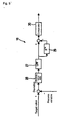
- Fig. 1 is a block diagram of a temperature control system having a temperature controller of the present invention, in which a portion corresponding to the above described Fig. 17 is provided with the same reference symbol.
- the temperature of a controlled system 1 such as a heating furnace is detected by a temperature sensor 2 and input to a temperature controller 3, and the temperature controller 3 performs a PID operation or the like in accordance with a target value (set temperature) and a detected temperature (process variable) to output an operational signal (manipulated variable) to an SSR 4, and controls power distribution to a heater 5 by an AC power supply 6 to control the temperature of the controlled system 1 so that the temperature becomes a target value.
- the temperature controller 3 has a display section 60 for displaying the present temperature and a set temperature or the like, an up key 61, down key 62, and mode key 63 at its front.
- the temperature controller 3 has a sensor input circuit 7 to which a feedback input is supplied from the temperature sensor 2, A/D conversion circuit 8, filter 9 according to software processing, control section (control means) 10 for performing a PID operation or the like, D/A conversion circuit 11, and output circuit 12.
- control section (control means) 10 for performing a PID operation or the like D/A conversion circuit 11, and output circuit 12.
- the above configuration is basically the same as that of a conventional example.
- the temperature controller 3 of this embodiment has a built-in trouble detection apparatus 13 so that a trouble in a temperature control loop such as a disconnection or short circuit can be accurately detected with a simple configuration at a low cost.
- the trouble detection apparatus 13 and the above control section 10 and filter 9 are constituted by, for example, a microcomputer.
- the trouble detection apparatus 13 has a trouble detection section 14 and trouble alarm section 15. As shown in Fig. 3 , the trouble detection section 14 has first determination means 16 for determining whether a deviation obtained by subtracting an process variable (detected temperature) from a target value (set temperature) exceeds a predetermined positive or negative threshold value, measurement means 17 for measuring the period in which the deviation exceeds the threshold value in accordance with a determination result by the first determination means 16, second determination means 18 for determining whether the period in which the deviation exceeds the threshold value continues for a certain period or more, third determination means 19 for determining whether the absolute value of the deviation decreases, that is, the detected temperature approaches the set temperature, and trouble determination means 20 for determining that a trouble occurs when the period in which the deviation exceeds the threshold value continues for a certain period or more and the absolute value of the deviation does not decrease.
- first determination means 16 for determining whether a deviation obtained by subtracting an process variable (detected temperature) from a target value (set temperature) exceeds a predetermined positive or negative threshold value
- a trouble determination output by the trouble determination means 20 is supplied to the trouble alarm section 15 and the trouble alarm section 15 outputs an alarm signal to an external unit. It is a matter of course that it is allowed to display an alarm or the like on the temperature controller 3 in accordance with the alarm signal.
- Fig. 4 is an illustration showing a configuration of the third determination means 19 for determining whether the absolute value of a deviation decreases.
- the absolute value of the present deviation E now obtained by subtracting a process variable from a target value is captured by an absolute-value circuit 21 while the absolute value of the deviation E old before at least two sampling times or more delayed by a delay circuit 22 is captured by an absolute-value circuit 23, the difference between the absolute values is calculated and compared with a default such as "0" by a comparator 24, and when the difference is equal to or more than the default, a high-level output is supplied to an AND circuit 25 but when the difference is less than the default, a low-level output is supplied to the AND circuit 25.
- a default such as "0"
- the AND circuit 25 supplies a high-level output when the deviations F old and S now have the same symbol and the difference between absolute values is equal to or more than a default.
- the sampling cycle of the third determination means 19 is set to a cycle capable of determining whether a deviation decreases in accordance with the characteristic or the like of a controlled system. For example, it is allowed to set the cycle to several seconds or several minutes.
- Fig. 5 is an illustration showing another configuration of the third determination means 19.
- the absolute value of a deviation is input to a low-pass filter 27 to determine that the absolute value of the deviation does not decrease when the difference value or derivative value of output values of the low-pass filter 27 is equal to or more than a default.
- the absolute value of a deviation obtained by subtracting a process variable from a target value is captured by an absolute-value circuit 28 to input it to the low-pass filter 27, the difference between an output of the low-pass filter and an output of the low-pass filter 27 before at least two sampling times or more delayed by a delay circuit 29 is calculated and compared with a default by a comparator 30, and when the difference is equal to or more than the default, a high-level output showing that the absolute value of the deviation does not decrease is supplied.
- Fig. 5 because it is possible to remove noises by the low-pass filter 27, it is possible to prevent a malfunction due to noises and it is allowed to set a sampling cycle to, for example, 0.1 or 0.5 seconds which is shorter than the case of the configuration in Fig. 4 .
- Fig. 6 is a flowchart of the trouble detection by a trouble detection apparatus having the above configuration.
- timer count constituting the measurement means 17 is reset (step n1) to determine whether a deviation is equal to or more than a positive or negative threshold value (step n2).
- step n1 is restarted
- time count is performed for measurement (step n3) to determine whether a counted value becomes a threshold value or more corresponding to a certain period (step n4).
- step n2 is restarted.
- step n4 when the counted value becomes the threshold value or more corresponding to the certain period, it is determined whether the absolute value of a deviation currently decreases as described above (step n5).
- step n2 When the absolute value currently decreases, step n2 is restarted.
- step n5 when the absolute value of the deviation does not currently decrease, that is, when the period in which the deviation exceeds the threshold value continues for a certain period or more and the absolute value of the deviation does not decrease, it is determined that a trouble occurs in a control loop and a trouble alarm is output to end the operation (step n6).
- the threshold value of a deviation is decided as a value obtained by multiplying a proportional band obtained through auto-tuning by a default such as "1" and the certain period is decided as a value obtained by multiplying the dead time obtained through auto-tuning by a default such as "2".
- it is allowed to decide the certain period in accordance with integral time or derivative time instead of dead time. Furthermore, it is allowed to set the threshold value and the certain period so that they can be input through setting by the keys 61 to 63 and it is allowed to decide the threshold value and the certain period without depending on a proportional band or dead time.
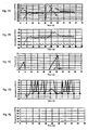
- Figs. 7A to 7E show normal operations, in which Fig. 7A shows target value (continuous line), true controlled variables (broken line), manipulated variable (alternate long and short dash line), and disturbance manipulated variable (alternate long and two short dashes line), Fig. 7B shows target value (continuous line), process variable (broken line), and sensor noise (alternate long and short dash line), Fig. 7C shows counted value (continuous line) of a timer counter serving as measurement means and determination output (broken line) of the second determination means 18 for determining whether a period in which a deviation exceeds a threshold value continues for a certain period or more, and Fig.
- FIG. 7D shows difference (continuous line) between absolute values of deviations serving as inputs of the comparator 24 in Fig. 4 and determination output (broken line) of the third determination means 19 for determining whether the absolute value of a deviation decreases
- Fig. 7E shows trouble determination output (continuous line) of the trouble determination means 20.
- 0°C corresponds to ordinary temperature.
- these time charts respectively show one-second one-sampling data, in which outputs slightly gently change.
- the timer counter performs measurement. However, the deviation becomes the threshold value or less before the measured value reaches the certain period and thereby, the time counter is reset.
- the deviation is kept equal to or less than the threshold value until a disturbance manipulated variable is applied. Therefore, measurement is not performed by the timer counter.
- the difference between absolute values of deviations also fluctuates around a default or 0 in the case of this example and a change that an determination output showing that the absolute value of a deviation does not decrease is output or not output is repeated.
- the deviation is equal to or less than the threshold value, no trouble determination output is output as shown in Fig. 7E .
- a trouble determination output is not output under the normal state.
- Figs. 8A to 8E show operations of an SSR serving as the above operation unit when a short circuit occurs, in which Fig. 8A shows target value (continuous line) and true controlled variable (broken line), Fig. 8B shows target value (continuous line) and process variable (broken line), Fig. 8C shows counted value (continuous line) of a timer counter serving as measurement means and determination output (broken line) of the second determination means 18 for determining whether a period in which a deviation exceeds a threshold value continues for a certain period or more, Fig. 8D shows difference (continuous line) between absolute values of deviations and determination output (broken line) of the third determination means 19 for determining whether the absolute value of a deviation decreases, and Fig. 8E shows trouble determination output (continuous line) of the trouble determination means 20.
- the timer counter performs measurement as shown in Fig. 8C .
- the deviation becomes equal to or less than the threshold value before the measured value reaches the above certain period and thereby, the timer counter is reset.
- the timer counter serving as measurement means performs measurement, and when the measured value reaches a certain period, a determination output showing that a period in which a deviation exceeds a threshold value continues for a certain period or more is output as shown in FIG 8C .
- a determination output showing that the absolute value of a deviation does not decrease is output as shown in Fig. 8D and thereby, a trouble determination output is output as shown in Fig. 8E .
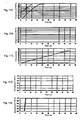
- Figs. 9A to 9E show operations when a heater is disconnected, in which Fig. 9A shows target value (continuous line), true controlled variable (broken line), and manipulated variable (alternate long and short dash line), Fig. 9B shows target value (continuous line) and process controlled variable (broken line), Fig. 9C shows counted value (continuous line) of a timer counter serving as measurement means and determination output (broken line) of the second determination means 18 for determining whether a period in which a deviation exceeds a threshold value continues for a certain period or more, Fig.
- FIG. 9D shows difference (continuous line) between absolute values of deviations and determination output (broken line) of the third determination means 19 for determining whether a period in which the absolute value of a deviation decreases
- Fig. 9E shows trouble determination output (continuous line) of the trouble determination means 20.
- a heater When a heater is disconnected, no manipulated variable is applied as shown in Fig. 9A , the process controlled variable decreases and the deviation exceeds the threshold value as shown in Fig. 9B , and the timer counter serving as measurement means performs measurement as shown in Fig. 9C and when the measured value reaches a certain period, outputs a determination output showing that a period in which a deviation exceeds a threshold value continues for a certain period or more.
- a determination output showing that the absolute value of a deviation does not decrease is output as shown in Fig. 9D and thereby, a trouble determination output is output as shown in Fig. 9E .
- Figs. 10A to 10E show operations when a sensor is disconnected, in which Fig. 10A shows target value (continuous line), true controlled variable (broken line), and manipulated variable (alternate long and short dash line), Fig. 10B shows target value (continuous line) and process variable (broken line), Fig. 10C shows counted value of a timer counter serving as measurement means and determination output of the second determination means 18 (broken line) for determining whether a period in which a deviation exceeds a threshold value continues for a certain period or more, Fig. 10D shows difference (continuous line) between absolute values of deviations and determination output of the third determination means 19 for determining whether the absolute value of a deviation decreases, and Fig. 10E shows trouble determination output of the trouble determination means 20.
- Fig. 10A shows target value (continuous line), true controlled variable (broken line), and manipulated variable (alternate long and short dash line)
- Fig. 10B shows target value (continuous line) and process variable (bro
- the true controlled variable shown in Fig. 10A becomes a very high temperature as a sensor input (process variable) as shown in Fig. 10B and therefore, the manipulated variable becomes 0 as shown in Fig. 10A .
- the process variable greatly departs from the target value and the deviation exceeds the threshold value as shown in Fig. 10B
- the timer counter serving as measurement means performs measurement, and when the measured value reaches a certain period, a determination output showing that a period in which a deviation exceeds a threshold value continues for a certain period or more is output as shown in Fig. 10C .
- a determination output showing that the absolute value of a deviation does not decrease is output as shown in Fig. 10D and thereby, a trouble determination output is output as shown in Fig. 10E .
- Figs. 11A to 11E show operations when a sensor is short-circuited, in which Fig. 11A shows target value (continuous line), true controlled variable(broken line), and manipulated variable (alternate long and short dash line), Fig. 11B shows target value (continuous line), and process variable (broken line), Fig. 11C shows counted value (continuous line) of a timer counter serving as measurement means and determination output of the second determination means 18 for determining whether a period in which a deviation exceeds a threshold value continues for a certain period, Fig. 11D shows difference (continuous line) between absolute values of deviations and determination output of the third determination means 19 for determining whether the absolute value of a deviation decreases, and Fig. 11E shows trouble determination output (continuous line) of the trouble determination means 20.
- the timer counter serving as measurement means performs measurement and when the measured value reaches a certain period, outputs a determination output showing that a period in which a deviation exceeds a threshold value continues for a certain period or more is output as shown in Fig. 11C .
- the present invention makes it possible to detect not only heater disconnection, SSR short-circuit, sensor short-circuit, and sensor disconnection but also every trouble causing the phenomenon that a deviation does not decrease. For example, it is possible to detect power failure of a heater power source, breakdown of an A/D converter or D/A converter, trouble of a sensor input circuit, trouble of an output circuit, and large disturbance exceeding a heater capacity as troubles.
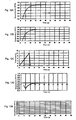
- Figs. 12A to 12E show operations when a steady manipulated variable is 100%, in which Fig. 12A shows target value (continuous line), true controlled variable (broken line), and manipulated variable (alternate long and short dash line), Fig. 12B shows target value (continuous line) and process variable (broken line), Fig. 12C shows counted value (continuous line) of a timer counter serving as measurement means and determination output (broken line) of the second determination means 18 for determining whether a period in which a deviation exceeds a threshold value continues for a certain period or more, Fig.
- Fig. 12D shows difference (continuous line) between absolute values of deviations and determination output (broken line) of the third determination means 19 for determining whether the absolute value of a deviation decreases
- Fig. 12E shows trouble determination output (continuous line) of the trouble determination means 20.
- the target value overlaps with the manipulated variable.
- a steady manipulated variable is not detected as a trouble even if the variable is 100%.
- the variable is erroneously detected as a trouble.
- Fig. 13 is a block diagram of a trouble detection section 14-1 of a temperature controller of another embodiment of the present invention, in which a portion corresponding to that in the above Fig. 3 is provided with the same reference symbol.
- the trouble determination means 20 determines that a trouble occurs and outputs a trouble determination signal.
- the above selecting and setting of condition signals are performed by referring to an operation manual or the like, selecting a mode through operations of various keys 61 to 63 and selecting desired condition signals.
- trouble determination means can select and set, for example, an OR condition other than an AND condition.
- Fig. 14 is a block diagram of a temperature control system of still another embodiment of the present invention, in which a portion corresponding to that in Fig. 1 is provided with the same reference symbol.
- a temperature controller 3-1 of this embodiment has a condition-signal generation section 65 instead of the trouble detection section 14 and trouble alarm section 15.
- the condition-signal generation section 65 generates a first condition signal which is a determination output of the second determination means (first condition-signal output means) 18, a second condition signal which is a determination output of the third determination means (second condition-signal output means) 19, and upper-limit alarm signal, lower-limit alarm signal, and deviation alarm signal which are alarm signals output from the alarm-signal generation sections 66 to 68 and outputs the signals to a programmable controller 70 as condition signals.
- a trouble is detected by a trouble detection section 71 of the programmable controller 70 to which the above condition signals are supplied. Operations of the trouble detection section 71 are set by the programmable controller 70 and performed the same as the embodiment 1 or 2 does.
- Fig. 16 is a block diagram of a temperature control system of another embodiment of the present invention, in which a portion corresponding to that in Fig. 1 is provided with the same reference symbol.
- a temperature controller 3-2 has an output terminal for outputting a target value and a controlled variable to an external unit and a trouble detection apparatus 13-1 detects the same trouble as the embodiment 1 does in accordance with the target value and controlled variable supplied from the temperature controller 3-2.
- the trouble detection apparatus 13-1 has a trouble detection section 14 and a trouble alarm section 15 the same as the trouble detection apparatus 13 of the embodiment 1 does and detects the same trouble as the embodiment 1 does.
- a target value and controlled variable are output from the temperature controller 3-2 to the trouble detection apparatus 13-1.
- it is also allowed to output a deviation or output only a target value and capture a detected temperature from a sensor 2.
- a state in which a deviation exceeds a threshold value may continue for a certain period and a condition that the absolute value of the deviation does not decrease may be satisfied.
- a change of the ramp-like target values it is necessary not to detect a trouble while the target values are changed.
- a trouble occurs when a state in which a deviation exceeds a threshold value continues for a certain period and the absolute value of the deviation does not decrease. Therefore, it is possible to detect various troubles such as heater disconnection, sensor disconnection, and sensor short-circuit each of which causes a phenomenon that the absolute value of a deviation does not decrease with a simple configuration at a low cost without using a current sensor or the like. Moreover, it is possible to detect a trouble at a high accuracy compared to the case of a conventional example which detects a trouble by using a manipulated variable.
Claims (6)
- Störungserkennungsverfahren zur Erkennung einer Störung in einem Regelkreis, welcher Steuermittel zur Ausgabe einer Stellgröße für eine Regelstrecke gemäß einer Abweichung zwischen einer von der Regelstrecke zurückgelieferten Prozessvariablen und einem Sollwert enthält, gekennzeichnet dadurch, dass das Verfahren umfaßt,einen Erkennungsschritt des Erkennens, dass eine Störung auftritt, wenn ein Zustand, in dem die Abweichung einen Schwellenwert überschreitet, für eine bestimmte Zeitdauer oder länger fortdauert und der Absolutwert der Abweichung nicht abnimmt.
- Störungserkennungsverfahren gemäß Anspruch 1, wobei der Erkennungsschritt umfasst:einen ersten Bestimmungsschritt des Bestimmens, ob die Abweichung einen Schwellenwert überschreitet;einen Messschritt des Messens der Zeitdauer, in der die Abweichung den Schwellenwert gemäß eines Bestimmungsergebnisses des ersten Bestimmungsschritts überschreitet;einen zweiten Bestimmungsschritt des Bestimmens, ob die Zeitdauer gemäß einem Meßergebnis des Messschritts, in der die Abweichung den Schwellenwert überschreitet, für eine bestimmte Zeitdauer oder länger fortdauert;einen dritten Bestimmungsschritt des Bestimmens ob der Absolutwert der Abweichung abnimmt; undeinen Störungsbestimmungsschritt des Bestimmens, dass eine Störung auftritt, wenn die Zeitdauer, in der die Abweichung den Schwellenwert überschreitet, für eine bestimmte Zeitdauer oder länger fortdauert und der Absolutwert der Abweichung nicht abnimmt gemäß Bestimmungsergebnissen des zweiten und des dritten Bestimmungsschritts.
- Störungserkennungsvorrichtung (13-1) zur Erkennung einer Störung in einem Regelkreis, der Steuermittel zur Ausgabe einer Stellgröße für eine Regelstrecke gemäß einer Abweichung zwischen einer von der Regelstrecke zurückgelieferten Prozessvariablen und einem Sollwert enthält, dadurch gekennzeichnet, dass die Vorrichtung umfasst:erste Bestimmungsmittel (16) zur Bestimmung, ob die Abweichung einen Schwellenwert überschreitet;Messmittel (17) zum Messen der Zeitdauer, in der die Abweichung den Schwellenwert gemäß eines Bestimmungsergebnisses der ersten Bestimmungsmittel überschreitet;zweite Bestimmungsmittel (18) zur Bestimmung, ob die Zeitdauer, in der die Abweichung den Schwellenwert gemäß einem Messergebnis der Messmittel überschreitet, für eine bestimmte Zeitdauer oder länger fortdauert;dritte Bestimmungsmittel (19) zur Bestimmung, ob der Absolutwert der Abweichung abnimmt; undStörungsbestimmungsmittel (20) zur Bestimmung, dass eine Störung auftritt, wenn die Zeitdauer in der die Abweichung den Schwellenwert überschreitet, für eine bestimmte Zeitdauer oder länger fortdauert und der Absolutwert der Abweichung nicht abnimmt gemäß Bestimmungsergebnissen der zweiten und der dritten Bestimmungsmittel,
- Temperaturregler (3), umfassend:Steuermittel (10) zur Ausgabe einer Stellgröße für eine Regelstrecke gemäß einer Abweichung zwischen einer von der Regelstrecke zurückgelieferten Prozessvariablen und einem Sollwert; gekennzeichnet durchStörungserkennungsmittel (13) zur Erkennung, dass eine Störung in einem Regelkreis auftritt, wenn ein Zustand, in dem die Abweichung einen Schwellenwert überschreitet, für eine bestimmte Zeitdauer oder länger fortdauert und der Absolutwert der Abweichung nicht abnimmt.
- Temperaturregler gemäß Anspruch 4, wobei die Störungserkennungsmittel (13) aufweisen:erste Bestimmungsmittel (16) zur Bestimmung, ob die Abweichung den Schwellenwert überschreitet;Messmittel (17) zur Messung der Zeitdauer, in der die Abweichung den Schwellenwert gemäß eines Bestimmungsergebnisses der ersten Bestimmungsmittel überschreitet;zweite Bestimmungsmittel (18) zur Bestimmung, ob die Zeitdauer gemäß einem Messergebnis der Messmittel, in der die Abweichung den Schwellenwert überschreitet, für eine bestimmte Zeitdauer oder länger fortdauert;dritte Bestimmungsmittel (19) zur Bestimmung, ob der Absolutwert der Abweichung abnimmt; undStörungsbestimmungsmittel (20) zur Bestimmung, dass eine Störung auftritt, wenn die Zeitdauer, in der die Abweichung den Schwellenwert überschreitet, für eine bestimmte Zeitdauer oder länger fortdauert und der Absolutwert der Abweichung nicht abnimmt gemäß Bestimmungsergebnissen der zweiten und dritten Bestimmungsmittel.
- Temperaturregler gemäß Anspruch 3 oder 4, wobei der Regelkreis ein PID-Regelkreis ist, die Steuermittel eine PID-Steuerung durchführen, und der Temperaturregler Entscheidungsmittel umfasst, welche den Schwellenwert gemäß einem Proportionalitätsbereich feststellen, der mittels selbsttätigem Abstimmen erhalten wird und die bestimmte Zeitdauer gemäß einer Stillstandszeit, integrierten Zeit oder differenzierten Zeit feststellen, die durch selbsttätigem Abstimmen erhalten werden.
Applications Claiming Priority (4)
| Application Number | Priority Date | Filing Date | Title |
|---|---|---|---|
| JP2002170997 | 2002-06-12 | ||
| JP2002170997 | 2002-06-12 | ||
| JP2002339237A JP3451554B1 (ja) | 2002-06-12 | 2002-11-22 | 異常検出方法、異常検出装置および温度調節器 |
| JP2002339237 | 2002-11-22 |
Publications (2)
| Publication Number | Publication Date |
|---|---|
| EP1376285A1 EP1376285A1 (de) | 2004-01-02 |
| EP1376285B1 true EP1376285B1 (de) | 2010-11-03 |
Family
ID=29218019
Family Applications (1)
| Application Number | Title | Priority Date | Filing Date |
|---|---|---|---|
| EP03012379A Expired - Lifetime EP1376285B1 (de) | 2002-06-12 | 2003-05-30 | Störungserkennungsverfahren, -vorrichtung und Temperaturregler |
Country Status (5)
| Country | Link |
|---|---|
| US (1) | US7117124B2 (de) |
| EP (1) | EP1376285B1 (de) |
| JP (1) | JP3451554B1 (de) |
| CN (2) | CN2674493Y (de) |
| DE (1) | DE60334757D1 (de) |
Families Citing this family (27)
| Publication number | Priority date | Publication date | Assignee | Title |
|---|---|---|---|---|
| JP4131272B2 (ja) * | 2005-06-28 | 2008-08-13 | オムロン株式会社 | 窓開閉制御装置 |
| JP4839702B2 (ja) * | 2005-07-04 | 2011-12-21 | オムロン株式会社 | 温度制御方法、調整装置、温度調節器、プログラム、記録媒体および熱処理装置 |
| CN102508123B (zh) * | 2011-09-29 | 2014-04-16 | 广州松下空调器有限公司 | 负离子发生器异常放电的检测方法 |
| JP5923416B2 (ja) * | 2012-09-12 | 2016-05-24 | アズビル株式会社 | 制御装置 |
| JP6216589B2 (ja) * | 2013-09-24 | 2017-10-18 | アズビル株式会社 | 不具合検知システムおよび不具合検知方法 |
| JP6200261B2 (ja) * | 2013-10-01 | 2017-09-20 | アズビル株式会社 | 不具合検知システムおよび不具合検知方法 |
| KR102207463B1 (ko) * | 2014-04-14 | 2021-01-26 | 삼성전자주식회사 | 오븐 및 그 제어 방법 |
| CN107209511B (zh) * | 2015-02-24 | 2020-06-09 | 东芝三菱电机产业系统株式会社 | 监视控制装置 |
| CN104764491A (zh) * | 2015-04-08 | 2015-07-08 | 深圳市康康网络技术有限公司 | 设备使用状态识别方法及电子设备 |
| JP6581833B2 (ja) * | 2015-07-30 | 2019-09-25 | アズビル株式会社 | アクチュエータ不具合検知装置、制御装置および方法 |
| CN105511524A (zh) * | 2015-12-01 | 2016-04-20 | 成都铁安科技有限责任公司 | 一种在线探伤装置耦合水池的加热装置及方法 |
| JP6499718B2 (ja) * | 2017-06-19 | 2019-04-10 | ファナック株式会社 | シール部材の異常摩耗検知装置及び回転体装置 |
| JP6943683B2 (ja) * | 2017-08-25 | 2021-10-06 | アズビル株式会社 | 調節計および劣化位置検出方法 |
| JP6706307B2 (ja) * | 2017-10-18 | 2020-06-03 | 株式会社リガルジョイント | 複数のバルブユニットの個別流量制御装置 |
| CN107843279B (zh) * | 2017-11-02 | 2020-09-25 | 宁波中车时代传感技术有限公司 | 一种具有自检测故障及自我调节功能的传感器电路 |
| JP7134652B2 (ja) * | 2018-03-12 | 2022-09-12 | 曙ブレーキ工業株式会社 | 異常検知方法および異常検知装置 |
| CN109031000B (zh) * | 2018-08-03 | 2019-08-16 | 贵州电网有限责任公司电网规划研究中心 | 一种基于非故障扰动就地测量电网短路容量的方法及系统 |
| JP7103164B2 (ja) * | 2018-10-31 | 2022-07-20 | オムロン株式会社 | 温度異常検知システム、温度異常検知方法、およびプログラム |
| JP7088056B2 (ja) * | 2019-02-04 | 2022-06-21 | 株式会社デンソー | 粒子状物質検出センサ |
| JP2020187685A (ja) * | 2019-05-17 | 2020-11-19 | アズビル株式会社 | 温度調節計および異常判断方法 |
| JP2020187682A (ja) * | 2019-05-17 | 2020-11-19 | アズビル株式会社 | 温度調節計および異常判断方法 |
| JP7255358B2 (ja) * | 2019-05-28 | 2023-04-11 | オムロン株式会社 | 異常検知装置、異常検知方法およびプログラム |
| CN111143102B (zh) * | 2019-12-13 | 2024-01-19 | 东软集团股份有限公司 | 异常数据检测方法、装置、存储介质及电子设备 |
| CN111443667A (zh) * | 2020-03-27 | 2020-07-24 | 中海石油深海开发有限公司 | 一种防止液位变送器跳变系统关断的方法和装置 |
| CN111650345B (zh) * | 2020-07-14 | 2021-02-19 | 中科三清科技有限公司 | 大气环境污染检测数据的处理方法、装置、设备及介质 |
| CN112015165A (zh) * | 2020-08-27 | 2020-12-01 | 余姚市工易仪表有限公司 | 一种温控器自检方法、系统及其存储介质 |
| CN115129097A (zh) * | 2021-03-26 | 2022-09-30 | 浙江苏泊尔家电制造有限公司 | 一种防止烹饪器具测温异常的控制方法和烹饪器具 |
Family Cites Families (13)
| Publication number | Priority date | Publication date | Assignee | Title |
|---|---|---|---|---|
| US4935607A (en) * | 1986-12-10 | 1990-06-19 | Robertshaw Controls Company | Control unit and method of making the same |
| JPH0774961B2 (ja) * | 1988-04-07 | 1995-08-09 | 株式会社日立製作所 | オートチユーニングpid調節計 |
| JP2552177B2 (ja) | 1988-07-14 | 1996-11-06 | 理化工業株式会社 | 制御ループ系の異常検知装置 |
| US5249119A (en) * | 1990-05-02 | 1993-09-28 | Idemitsu Kosan Company Limited | Apparatus for and method of detecting a malfunction of a controller |
| US5197375A (en) * | 1991-08-30 | 1993-03-30 | The Middleby Corporation | Conveyor oven control |
| JPH05322261A (ja) | 1992-05-21 | 1993-12-07 | Fujitsu General Ltd | 空気調和機 |
| DE19616773C1 (de) * | 1996-04-26 | 1997-09-04 | Daimler Benz Ag | Funktionsüberwachte Kraftstoffeinspritzanlage |
| US5949677A (en) * | 1997-01-09 | 1999-09-07 | Honeywell Inc. | Control system utilizing fault detection |
| US5831524A (en) * | 1997-04-29 | 1998-11-03 | Pittway Corporation | System and method for dynamic adjustment of filtering in an alarm system |
| US6182022B1 (en) * | 1998-01-26 | 2001-01-30 | Hewlett-Packard Company | Automated adaptive baselining and thresholding method and system |
| JP3437807B2 (ja) * | 1999-10-18 | 2003-08-18 | 株式会社山武 | 制御演算装置及び制御演算方法 |
| JP2001280674A (ja) | 2000-03-29 | 2001-10-10 | Sanyo Electric Co Ltd | 空調装置の遠隔監視システム |
| JP3834216B2 (ja) * | 2000-09-29 | 2006-10-18 | 株式会社日立国際電気 | 温度制御方法 |
-
2002
- 2002-11-22 JP JP2002339237A patent/JP3451554B1/ja not_active Expired - Lifetime
-
2003
- 2003-05-30 EP EP03012379A patent/EP1376285B1/de not_active Expired - Lifetime
- 2003-05-30 DE DE60334757T patent/DE60334757D1/de not_active Expired - Lifetime
- 2003-06-05 US US10/454,817 patent/US7117124B2/en not_active Expired - Lifetime
- 2003-06-12 CN CNU032720084U patent/CN2674493Y/zh not_active Expired - Fee Related
- 2003-06-12 CN CNB031427634A patent/CN1262900C/zh not_active Expired - Lifetime
Also Published As
| Publication number | Publication date |
|---|---|
| CN2674493Y (zh) | 2005-01-26 |
| US20040034509A1 (en) | 2004-02-19 |
| JP3451554B1 (ja) | 2003-09-29 |
| DE60334757D1 (de) | 2010-12-16 |
| CN1262900C (zh) | 2006-07-05 |
| JP2004070913A (ja) | 2004-03-04 |
| EP1376285A1 (de) | 2004-01-02 |
| CN1470964A (zh) | 2004-01-28 |
| US7117124B2 (en) | 2006-10-03 |
Similar Documents
| Publication | Publication Date | Title |
|---|---|---|
| EP1376285B1 (de) | Störungserkennungsverfahren, -vorrichtung und Temperaturregler | |
| JP5684231B2 (ja) | 回線ノイズを検知・解析し、計測誤差を減少させる方法 | |
| EP1772960B1 (de) | Lastüberwachung | |
| JP4393873B2 (ja) | 送信器 | |
| EP3355136B1 (de) | Vorrichtung zur pid-steuerung, verfahren zur pid-steuerung und programm zur pid-steuerung | |
| US20160252375A1 (en) | Encoder signal processor having automatic adjustment function | |
| WO2016150761A2 (en) | Method and arrangement for automatic tuning of a controller | |
| US6992470B1 (en) | Switching power supply system for automatically regulating circuit operating frequency and method thereof | |
| US8285516B2 (en) | Systems, methods, and apparatus for determining steady state conditions in a gas turbine | |
| JP2006277417A (ja) | 冷却制御装置、および冷却制御方法 | |
| JPH10117484A (ja) | 常時商用給電型交流無停電電源回路 | |
| JP2004070932A (ja) | 異常検出方法、異常検出装置および温度調節器 | |
| JP3398142B2 (ja) | 圧縮機のサージング検出装置 | |
| JP6624303B2 (ja) | 温度測定器、温度調節計及び短絡判別プログラム | |
| US10608657B2 (en) | Analog-to-digital conversion apparatus and analog-to-digital conversion method | |
| JP2009053044A (ja) | 検出装置、制御装置及び温度調節計 | |
| JPH0224705A (ja) | 制御ループ系の異常検知装置 | |
| JP2020007920A (ja) | 液体ポンプの異常検出装置および方法 | |
| JP4248963B2 (ja) | 計時装置 | |
| US6853931B2 (en) | Method and device for inputting data into an electronic data processing device | |
| JP3791289B2 (ja) | 比例動作調節計 | |
| JP3019894B2 (ja) | ガス供給設備異常監視装置 | |
| CN114719945A (zh) | 控制性电子皮带秤流量控制精度自适应方法、系统和计算机介质 | |
| JPH11296233A (ja) | 半導体製造装置における流量制御装置の異常検出方法 | |
| JP2593110Y2 (ja) | 車両用燃料計 |
Legal Events
| Date | Code | Title | Description |
|---|---|---|---|
| PUAI | Public reference made under article 153(3) epc to a published international application that has entered the european phase |
Free format text: ORIGINAL CODE: 0009012 |
|
| AK | Designated contracting states |
Kind code of ref document: A1 Designated state(s): AT BE BG CH CY CZ DE DK EE ES FI FR GB GR HU IE IT LI LU MC NL PT RO SE SI SK TR |
|
| AX | Request for extension of the european patent |
Extension state: AL LT LV MK |
|
| 17P | Request for examination filed |
Effective date: 20040203 |
|
| AKX | Designation fees paid |
Designated state(s): DE FR GB IT |
|
| 17Q | First examination report despatched |
Effective date: 20050524 |
|
| GRAP | Despatch of communication of intention to grant a patent |
Free format text: ORIGINAL CODE: EPIDOSNIGR1 |
|
| GRAS | Grant fee paid |
Free format text: ORIGINAL CODE: EPIDOSNIGR3 |
|
| GRAA | (expected) grant |
Free format text: ORIGINAL CODE: 0009210 |
|
| RIN1 | Information on inventor provided before grant (corrected) |
Inventor name: YAMADA, TAKAAKI,C/O OMRON CORPORATION |
|
| AK | Designated contracting states |
Kind code of ref document: B1 Designated state(s): DE FR GB IT |
|
| REG | Reference to a national code |
Ref country code: GB Ref legal event code: FG4D |
|
| REF | Corresponds to: |
Ref document number: 60334757 Country of ref document: DE Date of ref document: 20101216 Kind code of ref document: P |
|
| PLBE | No opposition filed within time limit |
Free format text: ORIGINAL CODE: 0009261 |
|
| STAA | Information on the status of an ep patent application or granted ep patent |
Free format text: STATUS: NO OPPOSITION FILED WITHIN TIME LIMIT |
|
| 26N | No opposition filed |
Effective date: 20110804 |
|
| REG | Reference to a national code |
Ref country code: DE Ref legal event code: R097 Ref document number: 60334757 Country of ref document: DE Effective date: 20110804 |
|
| REG | Reference to a national code |
Ref country code: DE Ref legal event code: R082 Ref document number: 60334757 Country of ref document: DE Representative=s name: KILIAN KILIAN & PARTNER MBB PATENTANWAELTE, DE Ref country code: DE Ref legal event code: R082 Ref document number: 60334757 Country of ref document: DE Representative=s name: KILIAN KILIAN & PARTNER, DE |
|
| REG | Reference to a national code |
Ref country code: FR Ref legal event code: PLFP Year of fee payment: 14 |
|
| REG | Reference to a national code |
Ref country code: FR Ref legal event code: PLFP Year of fee payment: 15 |
|
| REG | Reference to a national code |
Ref country code: FR Ref legal event code: PLFP Year of fee payment: 16 |
|
| PGFP | Annual fee paid to national office [announced via postgrant information from national office to epo] |
Ref country code: IT Payment date: 20220412 Year of fee payment: 20 Ref country code: GB Payment date: 20220407 Year of fee payment: 20 Ref country code: FR Payment date: 20220408 Year of fee payment: 20 Ref country code: DE Payment date: 20220406 Year of fee payment: 20 |
|
| REG | Reference to a national code |
Ref country code: DE Ref legal event code: R071 Ref document number: 60334757 Country of ref document: DE |
|
| REG | Reference to a national code |
Ref country code: GB Ref legal event code: PE20 Expiry date: 20230529 |
|
| PG25 | Lapsed in a contracting state [announced via postgrant information from national office to epo] |
Ref country code: GB Free format text: LAPSE BECAUSE OF EXPIRATION OF PROTECTION Effective date: 20230529 |