EP1375154A2 - Verfahren zur Herstellung einer Düsenplatte für einen Tintenstrahldruckkopf - Google Patents
Verfahren zur Herstellung einer Düsenplatte für einen Tintenstrahldruckkopf Download PDFInfo
- Publication number
- EP1375154A2 EP1375154A2 EP03014273A EP03014273A EP1375154A2 EP 1375154 A2 EP1375154 A2 EP 1375154A2 EP 03014273 A EP03014273 A EP 03014273A EP 03014273 A EP03014273 A EP 03014273A EP 1375154 A2 EP1375154 A2 EP 1375154A2
- Authority
- EP
- European Patent Office
- Prior art keywords
- substrate
- layer
- wetting
- outside surface
- resist
- Prior art date
- Legal status (The legal status is an assumption and is not a legal conclusion. Google has not performed a legal analysis and makes no representation as to the accuracy of the status listed.)
- Granted
Links
- 238000000034 method Methods 0.000 title claims abstract description 120
- 230000008569 process Effects 0.000 title claims abstract description 109
- 238000004519 manufacturing process Methods 0.000 title claims abstract description 57
- 239000000758 substrate Substances 0.000 claims abstract description 246
- 238000009736 wetting Methods 0.000 claims abstract description 136
- 230000000873 masking effect Effects 0.000 claims abstract description 67
- 238000007747 plating Methods 0.000 claims abstract description 58
- 239000011810 insulating material Substances 0.000 claims abstract description 48
- VYPSYNLAJGMNEJ-UHFFFAOYSA-N Silicium dioxide Chemical compound O=[Si]=O VYPSYNLAJGMNEJ-UHFFFAOYSA-N 0.000 claims description 49
- 238000009499 grossing Methods 0.000 claims description 35
- 239000000377 silicon dioxide Substances 0.000 claims description 24
- 235000012239 silicon dioxide Nutrition 0.000 claims description 20
- 239000011248 coating agent Substances 0.000 claims description 16
- 238000000576 coating method Methods 0.000 claims description 16
- 239000000463 material Substances 0.000 claims description 10
- OKTJSMMVPCPJKN-UHFFFAOYSA-N Carbon Chemical compound [C] OKTJSMMVPCPJKN-UHFFFAOYSA-N 0.000 claims description 8
- 229910052799 carbon Inorganic materials 0.000 claims description 8
- 239000010949 copper Substances 0.000 claims description 8
- 230000001678 irradiating effect Effects 0.000 claims description 8
- 239000010935 stainless steel Substances 0.000 claims description 8
- 229910001220 stainless steel Inorganic materials 0.000 claims description 8
- 230000009471 action Effects 0.000 claims description 7
- 230000001590 oxidative effect Effects 0.000 claims description 7
- 229910052715 tantalum Inorganic materials 0.000 claims description 7
- GUVRBAGPIYLISA-UHFFFAOYSA-N tantalum atom Chemical compound [Ta] GUVRBAGPIYLISA-UHFFFAOYSA-N 0.000 claims description 7
- RYGMFSIKBFXOCR-UHFFFAOYSA-N Copper Chemical compound [Cu] RYGMFSIKBFXOCR-UHFFFAOYSA-N 0.000 claims description 6
- 229910052802 copper Inorganic materials 0.000 claims description 6
- 238000004080 punching Methods 0.000 claims description 5
- 239000000976 ink Substances 0.000 description 63
- 239000005871 repellent Substances 0.000 description 55
- 230000015572 biosynthetic process Effects 0.000 description 25
- 238000004140 cleaning Methods 0.000 description 12
- 238000004891 communication Methods 0.000 description 10
- 238000005498 polishing Methods 0.000 description 10
- 239000002585 base Substances 0.000 description 8
- 238000009713 electroplating Methods 0.000 description 8
- 239000010408 film Substances 0.000 description 8
- 229940058401 polytetrafluoroethylene Drugs 0.000 description 8
- 229920001343 polytetrafluoroethylene Polymers 0.000 description 8
- 239000004810 polytetrafluoroethylene Substances 0.000 description 8
- 230000005855 radiation Effects 0.000 description 8
- 125000006850 spacer group Chemical group 0.000 description 8
- 239000000853 adhesive Substances 0.000 description 7
- 230000001070 adhesive effect Effects 0.000 description 7
- 230000005499 meniscus Effects 0.000 description 7
- PXHVJJICTQNCMI-UHFFFAOYSA-N nickel Substances [Ni] PXHVJJICTQNCMI-UHFFFAOYSA-N 0.000 description 7
- 239000011347 resin Substances 0.000 description 7
- 229920005989 resin Polymers 0.000 description 7
- HEMHJVSKTPXQMS-UHFFFAOYSA-M Sodium hydroxide Chemical compound [OH-].[Na+] HEMHJVSKTPXQMS-UHFFFAOYSA-M 0.000 description 6
- 230000006866 deterioration Effects 0.000 description 6
- 239000012528 membrane Substances 0.000 description 6
- 230000004913 activation Effects 0.000 description 5
- 238000005229 chemical vapour deposition Methods 0.000 description 5
- 239000000243 solution Substances 0.000 description 5
- XUIMIQQOPSSXEZ-UHFFFAOYSA-N Silicon Chemical compound [Si] XUIMIQQOPSSXEZ-UHFFFAOYSA-N 0.000 description 4
- 230000008859 change Effects 0.000 description 4
- 238000003754 machining Methods 0.000 description 4
- 229910052710 silicon Inorganic materials 0.000 description 4
- 239000010703 silicon Substances 0.000 description 4
- PXGOKWXKJXAPGV-UHFFFAOYSA-N Fluorine Chemical compound FF PXGOKWXKJXAPGV-UHFFFAOYSA-N 0.000 description 3
- BOTDANWDWHJENH-UHFFFAOYSA-N Tetraethyl orthosilicate Chemical compound CCO[Si](OCC)(OCC)OCC BOTDANWDWHJENH-UHFFFAOYSA-N 0.000 description 3
- 239000003570 air Substances 0.000 description 3
- 239000007864 aqueous solution Substances 0.000 description 3
- 238000005238 degreasing Methods 0.000 description 3
- 230000008030 elimination Effects 0.000 description 3
- 238000003379 elimination reaction Methods 0.000 description 3
- 229910052731 fluorine Inorganic materials 0.000 description 3
- 239000011737 fluorine Substances 0.000 description 3
- 239000007769 metal material Substances 0.000 description 3
- 238000005240 physical vapour deposition Methods 0.000 description 3
- 230000009467 reduction Effects 0.000 description 3
- 230000007723 transport mechanism Effects 0.000 description 3
- 238000004506 ultrasonic cleaning Methods 0.000 description 3
- XKRFYHLGVUSROY-UHFFFAOYSA-N Argon Chemical compound [Ar] XKRFYHLGVUSROY-UHFFFAOYSA-N 0.000 description 2
- 239000004593 Epoxy Substances 0.000 description 2
- 229910052581 Si3N4 Inorganic materials 0.000 description 2
- 239000003086 colorant Substances 0.000 description 2
- 238000005530 etching Methods 0.000 description 2
- 238000011049 filling Methods 0.000 description 2
- 238000000227 grinding Methods 0.000 description 2
- 238000010438 heat treatment Methods 0.000 description 2
- 229910052451 lead zirconate titanate Inorganic materials 0.000 description 2
- HFGPZNIAWCZYJU-UHFFFAOYSA-N lead zirconate titanate Chemical compound [O-2].[O-2].[O-2].[O-2].[O-2].[Ti+4].[Zr+4].[Pb+2] HFGPZNIAWCZYJU-UHFFFAOYSA-N 0.000 description 2
- 229910052759 nickel Inorganic materials 0.000 description 2
- TWNQGVIAIRXVLR-UHFFFAOYSA-N oxo(oxoalumanyloxy)alumane Chemical compound O=[Al]O[Al]=O TWNQGVIAIRXVLR-UHFFFAOYSA-N 0.000 description 2
- 239000002245 particle Substances 0.000 description 2
- 238000002360 preparation method Methods 0.000 description 2
- 238000007639 printing Methods 0.000 description 2
- HQVNEWCFYHHQES-UHFFFAOYSA-N silicon nitride Chemical compound N12[Si]34N5[Si]62N3[Si]51N64 HQVNEWCFYHHQES-UHFFFAOYSA-N 0.000 description 2
- 229910002651 NO3 Inorganic materials 0.000 description 1
- NHNBFGGVMKEFGY-UHFFFAOYSA-N Nitrate Chemical compound [O-][N+]([O-])=O NHNBFGGVMKEFGY-UHFFFAOYSA-N 0.000 description 1
- 229910000831 Steel Inorganic materials 0.000 description 1
- 239000006061 abrasive grain Substances 0.000 description 1
- 239000002253 acid Substances 0.000 description 1
- 239000003513 alkali Substances 0.000 description 1
- 229910045601 alloy Inorganic materials 0.000 description 1
- 239000000956 alloy Substances 0.000 description 1
- 239000012080 ambient air Substances 0.000 description 1
- 229910052786 argon Inorganic materials 0.000 description 1
- QVGXLLKOCUKJST-UHFFFAOYSA-N atomic oxygen Chemical compound [O] QVGXLLKOCUKJST-UHFFFAOYSA-N 0.000 description 1
- 238000007611 bar coating method Methods 0.000 description 1
- 238000005452 bending Methods 0.000 description 1
- 229910010293 ceramic material Inorganic materials 0.000 description 1
- 238000010276 construction Methods 0.000 description 1
- 230000007797 corrosion Effects 0.000 description 1
- 238000005260 corrosion Methods 0.000 description 1
- 238000006073 displacement reaction Methods 0.000 description 1
- 239000007789 gas Substances 0.000 description 1
- 230000005484 gravity Effects 0.000 description 1
- 239000012535 impurity Substances 0.000 description 1
- 238000009413 insulation Methods 0.000 description 1
- 230000004048 modification Effects 0.000 description 1
- 238000012986 modification Methods 0.000 description 1
- LNOPIUAQISRISI-UHFFFAOYSA-N n'-hydroxy-2-propan-2-ylsulfonylethanimidamide Chemical compound CC(C)S(=O)(=O)CC(N)=NO LNOPIUAQISRISI-UHFFFAOYSA-N 0.000 description 1
- 150000004767 nitrides Chemical class 0.000 description 1
- 239000001301 oxygen Substances 0.000 description 1
- 229910052760 oxygen Inorganic materials 0.000 description 1
- 230000002265 prevention Effects 0.000 description 1
- 230000001681 protective effect Effects 0.000 description 1
- 238000004544 sputter deposition Methods 0.000 description 1
- 239000010959 steel Substances 0.000 description 1
- 239000000126 substance Substances 0.000 description 1
- XQMTUIZTZJXUFM-UHFFFAOYSA-N tetraethoxy silicate Chemical compound CCOO[Si](OOCC)(OOCC)OOCC XQMTUIZTZJXUFM-UHFFFAOYSA-N 0.000 description 1
- 239000010409 thin film Substances 0.000 description 1
- XLYOFNOQVPJJNP-UHFFFAOYSA-N water Substances O XLYOFNOQVPJJNP-UHFFFAOYSA-N 0.000 description 1
Images


Classifications
-
- B—PERFORMING OPERATIONS; TRANSPORTING
- B41—PRINTING; LINING MACHINES; TYPEWRITERS; STAMPS
- B41J—TYPEWRITERS; SELECTIVE PRINTING MECHANISMS, i.e. MECHANISMS PRINTING OTHERWISE THAN FROM A FORME; CORRECTION OF TYPOGRAPHICAL ERRORS
- B41J2/00—Typewriters or selective printing mechanisms characterised by the printing or marking process for which they are designed
- B41J2/005—Typewriters or selective printing mechanisms characterised by the printing or marking process for which they are designed characterised by bringing liquid or particles selectively into contact with a printing material
- B41J2/01—Ink jet
- B41J2/135—Nozzles
- B41J2/16—Production of nozzles
- B41J2/1621—Manufacturing processes
- B41J2/1632—Manufacturing processes machining
-
- B—PERFORMING OPERATIONS; TRANSPORTING
- B41—PRINTING; LINING MACHINES; TYPEWRITERS; STAMPS
- B41J—TYPEWRITERS; SELECTIVE PRINTING MECHANISMS, i.e. MECHANISMS PRINTING OTHERWISE THAN FROM A FORME; CORRECTION OF TYPOGRAPHICAL ERRORS
- B41J2/00—Typewriters or selective printing mechanisms characterised by the printing or marking process for which they are designed
- B41J2/005—Typewriters or selective printing mechanisms characterised by the printing or marking process for which they are designed characterised by bringing liquid or particles selectively into contact with a printing material
- B41J2/01—Ink jet
- B41J2/135—Nozzles
- B41J2/16—Production of nozzles
- B41J2/1606—Coating the nozzle area or the ink chamber
-
- B—PERFORMING OPERATIONS; TRANSPORTING
- B41—PRINTING; LINING MACHINES; TYPEWRITERS; STAMPS
- B41J—TYPEWRITERS; SELECTIVE PRINTING MECHANISMS, i.e. MECHANISMS PRINTING OTHERWISE THAN FROM A FORME; CORRECTION OF TYPOGRAPHICAL ERRORS
- B41J2/00—Typewriters or selective printing mechanisms characterised by the printing or marking process for which they are designed
- B41J2/005—Typewriters or selective printing mechanisms characterised by the printing or marking process for which they are designed characterised by bringing liquid or particles selectively into contact with a printing material
- B41J2/01—Ink jet
- B41J2/135—Nozzles
- B41J2/16—Production of nozzles
- B41J2/1607—Production of print heads with piezoelectric elements
- B41J2/1609—Production of print heads with piezoelectric elements of finger type, chamber walls consisting integrally of piezoelectric material
-
- B—PERFORMING OPERATIONS; TRANSPORTING
- B41—PRINTING; LINING MACHINES; TYPEWRITERS; STAMPS
- B41J—TYPEWRITERS; SELECTIVE PRINTING MECHANISMS, i.e. MECHANISMS PRINTING OTHERWISE THAN FROM A FORME; CORRECTION OF TYPOGRAPHICAL ERRORS
- B41J2/00—Typewriters or selective printing mechanisms characterised by the printing or marking process for which they are designed
- B41J2/005—Typewriters or selective printing mechanisms characterised by the printing or marking process for which they are designed characterised by bringing liquid or particles selectively into contact with a printing material
- B41J2/01—Ink jet
- B41J2/135—Nozzles
- B41J2/16—Production of nozzles
- B41J2/162—Manufacturing of the nozzle plates
-
- B—PERFORMING OPERATIONS; TRANSPORTING
- B41—PRINTING; LINING MACHINES; TYPEWRITERS; STAMPS
- B41J—TYPEWRITERS; SELECTIVE PRINTING MECHANISMS, i.e. MECHANISMS PRINTING OTHERWISE THAN FROM A FORME; CORRECTION OF TYPOGRAPHICAL ERRORS
- B41J2/00—Typewriters or selective printing mechanisms characterised by the printing or marking process for which they are designed
- B41J2/005—Typewriters or selective printing mechanisms characterised by the printing or marking process for which they are designed characterised by bringing liquid or particles selectively into contact with a printing material
- B41J2/01—Ink jet
- B41J2/135—Nozzles
- B41J2/16—Production of nozzles
- B41J2/1621—Manufacturing processes
- B41J2/1623—Manufacturing processes bonding and adhesion
-
- B—PERFORMING OPERATIONS; TRANSPORTING
- B41—PRINTING; LINING MACHINES; TYPEWRITERS; STAMPS
- B41J—TYPEWRITERS; SELECTIVE PRINTING MECHANISMS, i.e. MECHANISMS PRINTING OTHERWISE THAN FROM A FORME; CORRECTION OF TYPOGRAPHICAL ERRORS
- B41J2/00—Typewriters or selective printing mechanisms characterised by the printing or marking process for which they are designed
- B41J2/005—Typewriters or selective printing mechanisms characterised by the printing or marking process for which they are designed characterised by bringing liquid or particles selectively into contact with a printing material
- B41J2/01—Ink jet
- B41J2/135—Nozzles
- B41J2/16—Production of nozzles
- B41J2/1621—Manufacturing processes
- B41J2/1626—Manufacturing processes etching
-
- B—PERFORMING OPERATIONS; TRANSPORTING
- B41—PRINTING; LINING MACHINES; TYPEWRITERS; STAMPS
- B41J—TYPEWRITERS; SELECTIVE PRINTING MECHANISMS, i.e. MECHANISMS PRINTING OTHERWISE THAN FROM A FORME; CORRECTION OF TYPOGRAPHICAL ERRORS
- B41J2/00—Typewriters or selective printing mechanisms characterised by the printing or marking process for which they are designed
- B41J2/005—Typewriters or selective printing mechanisms characterised by the printing or marking process for which they are designed characterised by bringing liquid or particles selectively into contact with a printing material
- B41J2/01—Ink jet
- B41J2/135—Nozzles
- B41J2/16—Production of nozzles
- B41J2/1621—Manufacturing processes
- B41J2/164—Manufacturing processes thin film formation
- B41J2/1642—Manufacturing processes thin film formation thin film formation by CVD [chemical vapor deposition]
-
- B—PERFORMING OPERATIONS; TRANSPORTING
- B41—PRINTING; LINING MACHINES; TYPEWRITERS; STAMPS
- B41J—TYPEWRITERS; SELECTIVE PRINTING MECHANISMS, i.e. MECHANISMS PRINTING OTHERWISE THAN FROM A FORME; CORRECTION OF TYPOGRAPHICAL ERRORS
- B41J2/00—Typewriters or selective printing mechanisms characterised by the printing or marking process for which they are designed
- B41J2/005—Typewriters or selective printing mechanisms characterised by the printing or marking process for which they are designed characterised by bringing liquid or particles selectively into contact with a printing material
- B41J2/01—Ink jet
- B41J2/135—Nozzles
- B41J2/16—Production of nozzles
- B41J2/1621—Manufacturing processes
- B41J2/164—Manufacturing processes thin film formation
- B41J2/1643—Manufacturing processes thin film formation thin film formation by plating
-
- B—PERFORMING OPERATIONS; TRANSPORTING
- B41—PRINTING; LINING MACHINES; TYPEWRITERS; STAMPS
- B41J—TYPEWRITERS; SELECTIVE PRINTING MECHANISMS, i.e. MECHANISMS PRINTING OTHERWISE THAN FROM A FORME; CORRECTION OF TYPOGRAPHICAL ERRORS
- B41J2/00—Typewriters or selective printing mechanisms characterised by the printing or marking process for which they are designed
- B41J2/005—Typewriters or selective printing mechanisms characterised by the printing or marking process for which they are designed characterised by bringing liquid or particles selectively into contact with a printing material
- B41J2/01—Ink jet
- B41J2/135—Nozzles
- B41J2/14—Structure thereof only for on-demand ink jet heads
- B41J2/14201—Structure of print heads with piezoelectric elements
- B41J2/14209—Structure of print heads with piezoelectric elements of finger type, chamber walls consisting integrally of piezoelectric material
- B41J2002/14225—Finger type piezoelectric element on only one side of the chamber
-
- B—PERFORMING OPERATIONS; TRANSPORTING
- B41—PRINTING; LINING MACHINES; TYPEWRITERS; STAMPS
- B41J—TYPEWRITERS; SELECTIVE PRINTING MECHANISMS, i.e. MECHANISMS PRINTING OTHERWISE THAN FROM A FORME; CORRECTION OF TYPOGRAPHICAL ERRORS
- B41J2/00—Typewriters or selective printing mechanisms characterised by the printing or marking process for which they are designed
- B41J2/005—Typewriters or selective printing mechanisms characterised by the printing or marking process for which they are designed characterised by bringing liquid or particles selectively into contact with a printing material
- B41J2/01—Ink jet
- B41J2/135—Nozzles
- B41J2/14—Structure thereof only for on-demand ink jet heads
- B41J2/14201—Structure of print heads with piezoelectric elements
- B41J2002/14306—Flow passage between manifold and chamber
-
- Y—GENERAL TAGGING OF NEW TECHNOLOGICAL DEVELOPMENTS; GENERAL TAGGING OF CROSS-SECTIONAL TECHNOLOGIES SPANNING OVER SEVERAL SECTIONS OF THE IPC; TECHNICAL SUBJECTS COVERED BY FORMER USPC CROSS-REFERENCE ART COLLECTIONS [XRACs] AND DIGESTS
- Y10—TECHNICAL SUBJECTS COVERED BY FORMER USPC
- Y10T—TECHNICAL SUBJECTS COVERED BY FORMER US CLASSIFICATION
- Y10T29/00—Metal working
- Y10T29/49—Method of mechanical manufacture
- Y10T29/49401—Fluid pattern dispersing device making, e.g., ink jet
-
- Y—GENERAL TAGGING OF NEW TECHNOLOGICAL DEVELOPMENTS; GENERAL TAGGING OF CROSS-SECTIONAL TECHNOLOGIES SPANNING OVER SEVERAL SECTIONS OF THE IPC; TECHNICAL SUBJECTS COVERED BY FORMER USPC CROSS-REFERENCE ART COLLECTIONS [XRACs] AND DIGESTS
- Y10—TECHNICAL SUBJECTS COVERED BY FORMER USPC
- Y10T—TECHNICAL SUBJECTS COVERED BY FORMER US CLASSIFICATION
- Y10T29/00—Metal working
- Y10T29/49—Method of mechanical manufacture
- Y10T29/49789—Obtaining plural product pieces from unitary workpiece
- Y10T29/49798—Dividing sequentially from leading end, e.g., by cutting or breaking
Definitions
- the present invention relates to a nozzle plate which is to constitute a part of a print head of an ink-jet printer capable of ejecting an ink toward a print media so as to form a desired image on the print media.
- an ink-jet print head which is constituted by a plurality of thin plates which are laminated on and bonded to one another.
- Each of the laminated thin plates has apertures formed by, for example, an etching operation, so that the apertures formed in the laminated thin plates are mutually connected and cooperate with one another to form pressure chambers, manifold chambers, communication passages and nozzle holes within a laminated structure provided by the laminated thin plates.
- the ink-jet print head constituted by the laminated thin plates includes a head body and a nozzle plate which is bonded to a surface of the head body.
- the head body has the pressure chambers in each of which the ink is pressurized by activation of a piezoelectric element, and the communication passages for supplying the ink from the pressure chambers toward the nozzle holes.
- the nozzle plate has the nozzle holes through which the ink is ejected toward the print media. This ink-jet print head is capable of ejecting, through the nozzle holes, the ink in the form of fine droplets toward the print media at a high speed.
- the nozzle plate may be coated at its outside surface (which is to be opposed to the print media) with a plating layer having a non-wetting characteristic, in the interest of preventing the ejected ink from adhering to the nozzle plate.
- the plating layer is adapted to cover the entirety of the outside surface of the nozzle plate including an edge of opening of each of nozzle holes, for thereby preventing the ink from adhering to the edge of the opening of each nozzle hole.
- the diameter and density of the nozzle holes are reduced and increased, respectively, for satisfying recent demands for a further improved quality of printed images, it is extremely difficult to enable the plating layer to be formed to extend up to the edge of the opening of each nozzle hole.
- a process for forming the nozzle hole in the nozzle plate there is known a process including a step of piercing the nozzle plate by using a punch which has a generally conical shape configured to form a desired shape of the nozzle hole. Described more specifically, a portion of the nozzle plate (in which the nozzle hole is to be formed) is plastically deformed by the punch in a direction away from the inside surface of the nozzle plate toward the outside surface of the nozzle plate, such that a recess and a protrusion are formed in the inside and outside surfaces of the deformed portion of the nozzle plate, respectively.
- a process for forming the non-wetting plating layer there is known a process including a step of a masking step of masking the inside surface of the nozzle plate and the inner surface of each nozzle hole, and a non-wetting-layer forming step of forming the non-wetting plating layer on the outside surface of the nozzle plate.
- a resin is provided to cover the inside surface of the nozzle plate and a tapered portion of the inner surface of each nozzle hole, so that the outside surface of the nozzle plate and a small-diameter end portion of the inner surface of each nozzle hole (which portion is adjacent to the outside surface of the nozzle plate) remains unmasked.
- the non-wetting plating layer is formed to cover the outside surface of the nozzle plate and the small-diameter end portion of the inner surface of each nozzle hole which are not masked with the resin.
- An example of this process is disclosed by JP-A-2001-18398.
- the non-wetting plating layer As another technique for forming the non-wetting plating layer, there is known a process including a wetting-layer forming step of forming a wetting layer (made of a material having a wetting characteristic) on the inside surface of the nozzle plate, and a non-wetting layer forming step of forming the non-wetting layer on the outside surface of the nozzle plate and an end portion of the inner surface of each nozzle which portion is adjacent to the outside surface of the nozzle plate.
- the wetting layer serves as a masking member, so that the non-wetting layer is not deposited on the inside surface of the nozzle plate which is covered with the wetting layer.
- An example of this process is disclosed by JP-A-H9-85956.
- the non-wetting layer can not be formed accurately on a required area of the nozzle plate, because of difficulty in covering accurately the required portion of the inner surface of the nozzle hole with the resin, or in forming the wetting layer as the masking member accurately on the inside surface of the nozzle plate. That is, in the known techniques, it is difficult to stably establish a desired boundary between the wetting area and the non-wetting area in each nozzle hole, making it impossible to provide each nozzle hole with a desired characteristic of ink ejection.
- This object may be achieved according to any one of the following modes of the present invention, each of which is numbered like the appended claims and depends from the other mode or modes, where appropriate, to indicate and clarify possible combinations of elements or technical features. It is to be understood that the present invention is not limited to the technical features or any combinations thereof which will be described for illustrative purpose only. It is to be further understood that a plurality of elements or features included in any one of the following modes of the invention are not necessarily provided all together, and that the invention may be embodied without some of the elements or features described with respect to the same mode.
- a process of manufacturing a nozzle plate for an ink-jet print head including (a) a substrate having an outside surface which is to be opposed to a print media, an inside surface which is opposite to the outside surface and nozzle holes which are formed through the substrate so as to be open in the outside and inside surfaces, and (b) a non-wetting film or layer which has a non-wetting characteristic and which covers the outside surface of the substrate, the process comprising: (i) a masking step of applying a resist on the inside surface of the substrate, and charging the nozzle holes with the insulating material such that portions of the resist protrude outwardly from openings of the nozzle holes on the outside surface; (ii) a non-wetting-layer forming step of forming the non-wetting layer on the outside surface in a plating operation; and (iii) an unmasking step of removing the resist from the substrate.
- the masking step is implemented by applying the resist as an insulating material on the inside surface of the substrate and filling or charging each nozzle hole with the resist.
- each nozzle hole takes the form of a through-hole, an air can be discharged from each nozzle hole upon the charging of each nozzle hole with the resist, so that the inner surface of each nozzle hole can be reliably masked with the resist.
- the nozzle holes are charged with the resist such that portions of the resist protrude outwardly from openings of the respective nozzle holes (which openings are located on the outside surface of the substrate).
- the outwardly protruding portions of the resist may be eliminated either before or after the implementation of the non-wetting layer forming step. Where the protruding portions of the resist are eliminated before the non-wetting layer forming step, the protruding portions can be eliminated by planing or smoothing the outside surface of the substrate, for example, in a polishing or lapping operation.
- the protruding portions can be eliminated together with the non-protruding portion in the unmasking step. It is also noted that the technical features described in this mode (1) is applicable to the manufacturing process defined in any one of modes (2)-(11) which are described below.
- a process of manufacturing a nozzle plate for an ink-jet print head including (a) a substrate having an outside surface which is to be opposed to a print media, an inside surface which is opposite to the outside surface and nozzle holes which are formed through the substrate so as to be open in the outside and inside surfaces, and (b) a non-wetting layer which has a non-wetting characteristic and which covers the outside surface of the substrate, the process comprising: (i) a substrate setting step of setting the substrate on a support, such that the outside surface is positioned downwardly of the inside surface, without openings of the nozzle holes on the outside surface being in contact with the support; (ii) a masking step of applying an insulating material on the inside surface and charging the nozzle holes with the insulating material; (iii) a non-wetting-layer forming step of forming the non-wetting layer on the outside surface; and (iv) an unmasking step of removing the insulating material from the substrate, wherein the masking step includes
- the manufacturing process according to this mode (2) of the invention includes the substrate setting step which is implemented to set the substrate on the support such that the openings of the nozzle holes on the outside surface is not in contact with the support. Therefore, during the bar coating step in which the bar is moved on the resist disposed on the inside surface in a direction parallel to the inside surface, the outwardly protruding portions of the resist is prevented from being adhering to the outside surface of the substrate, thereby-avoiding an erroneous masking of the outside surface with the resist. That is, the non-wetting layer can be reliably formed on the entirety of the outside surface. Thus, it is possible to minimize a risk of clogging of each nozzle hole of the manufactured nozzle plate without reducing wettability of the inner surface of each nozzle hole. It is noted that the nozzle holes may be formed by punching the substrate as described below in the process of mode (5), or may be otherwise formed.
- a process of manufacturing a nozzle plate for an ink-jet print head including (a) a substrate having an outside surface which is to be opposed to a print media, an inside surface which is opposite to the outside surface and nozzle holes which are formed through the substrate so as to be open in the outside and inside surfaces, and (b) a non-wetting layer which has a non-wetting characteristic and which covers the outside surface of the substrate, the process comprising: (i) a through-holes forming step of forming through-holes as the nozzle holes in the substrate, by punching the substrate from the inside surface toward the outside surface; (ii) a masking step of applying an insulating material on the inside surface and charging the nozzle holes with the insulating material; (iii) a surface smoothing step of planing or smoothing the outside surface; (iv) a non-wetting-layer forming step of forming the non-wetting layer on the outside surface in a plating operation; and (v) an unmasking step of
- the masking step is implemented by applying the insulating material (such as a resist) on the inside surface of the substrate and filling or charging each nozzle hole with the insulating material. Since each nozzle hole takes the form of the through-hole, an air can be discharged from each nozzle hole upon the charging of each nozzle hole with the insulating material, so that the inner surface of each nozzle hole can be reliably masked with the insulating material. Further, in the masking step, it is possible to apply the insulating material into each nozzle hole such that portions of the insulating material protrude outwardly from openings of the nozzle holes (which openings are located on the outside surface of the substrate).
- the insulating material such as a resist
- the outwardly protruding portions of the insulating material can be eliminated in the surface smoothing step in which the outside surface of the substrate may be subjected to a polishing or lapping operation.
- This arrangement assures a reliable masking of the inner surface of each nozzle hole with the insulating material, without an erroneous masking of the outside surface with the insulating material.
- the boundary between the masked area and the unmasked area can coincide with an intersection between the inner surface of each nozzle hole and the outside surface of the substrate.
- the present manufacturing process assures a reliable formation of the non-wetting layer exclusively on a required area, i.e., the outside surface of the substrate, thereby minimizing a risk of clogging of each nozzle hole of the manufactured nozzle plate without reducing wettability of the inner surface of each nozzle hole. Still further, in the surface smoothing step, it is possible to eliminate not only the outwardly protruding portions but also burrs which have been formed at edges of the openings of the nozzle holes in the through-hole forming step. The simultaneous elimination of the outwardly protruding portions of the insulating material and the burrs leads to a reduced number of steps of the manufacturing process.
- a process of manufacturing a nozzle plate for an ink-jet print head including (a) a substrate having an outside surface which is to be opposed to a print media, an inside surface which is opposite to the outside surface and nozzle holes which are formed through the substrate so as to be open in the outside and inside surfaces, and (b) a non-wetting layer which has a non-wetting characteristic and which covers the outside surface of the substrate, the process comprising: (i) a masking step of applying an insulating material on the inside surface and charging the nozzle holes with the insulating material, by superposing the substrate on a resist layer formed of a resist as the insulting material, such that the inside surface is brought into contact with the resist layer, so that the nozzle holes are charged with the resist owing to a capillary action of the resist; (ii) a non-wetting-layer forming step of forming the non-wetting layer on the outside surface in a plating operation; and (iii) an unmasking step of removing the
- the masking step is implemented by superposing the substrate on the resist layer such that the inside surface is brought into contact with the resist layer, whereby each nozzle hole is charged with the resist owing to the capillary action of the resist.
- the resist has such a degree of viscosity that permits the portion of the resist layer (which portion is located right below each nozzle hole) to be drawn up, against a gravity, into each nozzle hole such that a top end of the drawn portion of the resist layer slightly protrudes from the opening of the corresponding nozzle hole on the outside surface of the substrate.
- the drawn portion of the resist does not cover the outside surface, since the capillary action of the resist occurs only in a narrow space, i.e., in a space within each nozzle hole. Therefore, the outside surface is not erroneously masked with the resist in the masking step, so that the non-wetting layer can be reliably formed on the entirety of the outside surface. Thus, it is possible to minimize a risk of clogging of each nozzle hole of the manufactured nozzle plate without reducing wettability of the inner surface of each nozzle hole. It is noted that the nozzle holes may be formed by punching the substrate as in the process of the above-described mode (5), or may be otherwise formed.
- a process of manufacturing a nozzle plate for an ink-jet print head including (a) a substrate having an outside surface which is to be opposed to a print media, an inside surface which is opposite to the outside surface and nozzle holes which are formed through the substrate so as to be open in the outside and inside surfaces, and (b) a non-wetting layer which has a non-wetting characteristic and which covers the outside surface of the substrate, the process comprising: (i) a masking step of covering the inside surface of the substrate with a masking member; (ii) a non-wetting-layer forming step of forming a non-wetting layer on the outside surface and inner surfaces of the nozzle holes; (iii) an unmasking step of removing the masking member from the substrate; and (iv) an irradiating step of irradiating portions of the non-wetting layer which cover the inner surfaces of the nozzle holes, such that the irradiated portions of the non-wetting layer lose the non-wetting characteristic
- the masking step is implemented by covering the inside surface of the substrate with the masking member. Unlike the above-described processes according to modes (1)-(10), the inner surface of the each nozzle hole does not have to be masked.
- the portion of the non-wetting layer which portion covers the inner surface of each nozzle hole is irradiated (e.g., with a high-energy radiation such as laser and plasma), so as to lose its non-wetting characteristic and then have a wetting characteristic.
- the other portion of the non-wetting layer, which portion covers the outside surface rather than the inner surface of each nozzle hole is not radiated whereby its non-wetting characteristic is maintained.
- the nozzle holes may be formed by punching the substrate as in the process of the above-described mode (5), or may be otherwise formed.
- nozzle plate for an ink-jet print head, the nozzle plate including (a) a substrate having an outside surface which is to be opposed to a print media, an inside surface which is opposite to the outside surface and nozzle holes which are formed through the substrate so as to be open in.
- a non-wetting layer which has a non-wetting characteristic and which covers the outside surface of the substrate, the process comprising: (i) a deforming step of plastically deforming portions of the substrate in which the nozzles holes are to be formed, in a direction away from the inside surface toward the outside surface, such that a recess and a protrusion are formed in the inside and outside surfaces of each of the deformed portions of the substrate, respectively; (ii) a covering-layer forming step of forming a covering film or layer on the inside surface and an inner surface of the recess; (iii) a surface smoothing step of smoothing the outside surface, so that the protrusion formed in the outside surface of each of the deformed portions of the substrate is eliminated whereby the recess formed in the inside surface of each of the deformed portions of the substrate converts into a corresponding one of the nozzle holes; and (iv) a non-wetting-layer forming step of forming the non-wetting layer on
- each protrusion is eliminated in the surface smoothing step, by smoothing the outside surface after the formation of the covering layer on the inside surface and the inner surface of each recess, so that each recess converts into the corresponding nozzle hole.
- an end face of the covering layer formed on the inner surface of each nozzle hole is precisely made flush with the outside surface of the substrate, so that the covering layer serving as a masking member in the non-wetting-layer forming step can be accurately formed on the inner surface of each nozzle hole, without any portion of the inner surface of each nozzle hole being unmasked with the covering layer, and without any portion of the outside surface of the substrate being erroneously masked with the covering layer.
- the boundary between the masked area and the unmasked area can coincide with an intersection between the inner surface of each nozzle hole and the outside surface of the substrate. Therefore, the present manufacturing process assures a reliable formation of the non-wetting layer exclusively on a required area, i.e., the outside surface of the substrate, thereby minimizing a risk of clogging of each nozzle hole of the manufactured nozzle plate without reducing wettability of the inner surface of each nozzle hole.
- the covering-layer forming step were implemented after the implementation of the surface smoothing step, namely, if the formation of the covering layer were made after the formation of the through-holes as the nozzle holes, the covering layer would be likely to be formed erroneously formed on a portion of the outside surface of the substrate adjacent to the opening of each nozzle hole. This leads to a failure of the formation of the non-wetting layer on the portion adjacent to the opening of each nozzle hole, thereby making it impossible to provide each nozzle hole with a desired characteristic of ink ejection.
- the end face of the covering layer can be made flush with the outside surface of the substrate, so that the covering layer serving as a masking member in the non-wetting-layer forming step can be accurately formed on the inner surface of each nozzle hole without its erroneous formation on the above-described portion of the outside surface of the substrate that is adjacent to the opening of each nozzle hole.
- the accurate formation of the covering layer on the inner surface of each nozzle hole leads to a reliable formation of desired-shaped meniscus of the ink at the opening of each nozzle hole.
- the thickness of the insulating layer is adjusted such that the non-wetting layer does not overhang each of the nozzle holes, namely, such that the non-wetting layer does not project from the inner surface of each nozzle hole toward the axis of the nozzle hole.
- the non-wetting layer grows in an isotropic manner in the process of its formation by the electrolytic plating, the non-wetting layer would protrude from the insulating layer formed on the inner surface of each nozzle hole toward the axis of the nozzle hole, if the thickness of the insulating layer were smaller than that of the non-wetting layer. If the non-wetting layer were formed to overhang each nozzle hole, an overhanging portion of the non-wetting layer would be easily broken upon application of impact to the layer, whereby the accuracy of the ink ejection would be deteriorated.
- the arrangement according to this mode (14) is effective to minimize risk of breakage of the non-wetting layer and accordingly avoid deterioration in accuracy of ejection of the ink, which could be caused in the event of undesirable change of configuration of the opening of each nozzle hole.
- a film or layer made of silicon dioxide is formed as the insulating layer in the insulating-layer forming step. It is more preferable that the layer is made of silicone dioxide containing carbon, as in the process according to mode (15) described below, rather than high-purity silicon dioxide having substantially no impurity.
- silicon dioxide is used for covering the inside surface of the nozzle plate substrate and the inner surface of each nozzle hole
- a layer provided by the high-purity silicon dioxide tends to be easily removed from the substrate during the surface smoothing step, because the layer of the high-purity silicon dioxide is inherently brittle.
- the removal of the silicon dioxide layer leads to a formation of the non-wetting layer on a non-required portion of the substrate such as the inner surface of each nozzle hole, thereby suffering from an undesirable reduction in the wettablity of the inner surface of each nozzle hole.
- the insulating layer is provided by the layer made of silicon dioxide containing carbon, and is accordingly provided with a lower degree of membrane stress than where the insulating layer is provided by the layer made of the high-purity silicon dioxide. Owing to its lower degree of membrane stress, the insulating layer is prevented from being undesirably removed from the substrate in the surface smoothing step, thereby making it possible to avoid an undesirable reduction in the wettablity of the inner surface of each nozzle hole.
- the layer of silicon dioxide containing carbon can be formed at a low temperature (e.g. 150°C) in accordance with CVD method.
- the deforming step is followed by the covering-layer forming step that is implemented to form the metallic layer made of a metallic material oxidizable under a condition under which the substrate is not oxidizable.
- the layer oxidizing step is implemented to oxidize the metallic layer such that the metallic layer converts into the oxidized layer having an insulating property. Therefore, in the stage before implementation of the non-wetting layer forming step, an end face of the oxidized or insulating layer formed on the inner surface of each nozzle hole is precisely made flush with the outside surface of the substrate, as in the manufacturing process according to the above-described mode (13).
- the insulating layer serving as a masking member in the non-wetting-layer forming step can be accurately formed on the inner surface of each nozzle hole, without any portion of the inner surface of each nozzle hole being unmasked with the insulating layer, and without any portion of the outside surface of the substrate being erroneously masked with the insulating layer. Therefore, the manufacturing process assures a reliable formation of the non-wetting layer exclusively on a required area, i.e., the outside surface of the substrate, thereby minimizing a risk of clogging of each nozzle hole of the manufactured nozzle plate without reducing wettability of the inner surface of each nozzle hole.
- the thickness of the metallic layer is adjusted such that the non-wetting layer does not overhang each of the nozzle holes, namely, such that the non-wetting layer does not project from the inner surface of each nozzle hole toward the axis of the nozzle hole.
- the non-wetting layer grows in an isotropic manner in the process of its formation by the electrolytic plating, the non-wetting layer would protrude from the oxidized metallic layer formed on the inner surface of each nozzle hole toward the axis of the nozzle hole, if the thickness of the oxidized metallic layer were smaller than that of the non-wetting layer. If the non-wetting layer were formed to overhang each nozzle hole, an overhanging portion of the non-wetting layer would be easily broken upon application of impact to the layer, whereby the accuracy of the ink ejection would be deteriorated.
- the arrangement according to this mode (18) is effective to minimize risk of breakage of the non-wetting layer and accordingly avoid deterioration in accuracy of ejection of the ink, which could be caused in the event of undesirable change of configuration of the opening of each nozzle hole.
- the tantalum or copper layer as the metallic layer can be oxidized by heating the metallic layer in an atmosphere, without affecting the substrate.
- the metallic layer can easily converts into the oxidized layer.
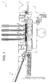
- FIG. 1 is a view showing almost the entirety of the ink-jet printer 1.
- Fig. 2 is a bottom view of the print heads 2 arranged in a media transporting direction.
- Fig. 3 is an enlarged view of one of the print heads 2.
- Fig. 4 is a cross sectional view of a laminated structure portion 18 of the print head 2 including a passage-defining unit 20.
- the ink-jet printer 1, equipped with the four print heads 2, has a media entrance portion 11 and a media exit portion 12 which are respectively located in the left and right as seen in Fig.1.
- a paper sheet as a print media is supplied through the media entrance portion 11, and is then transported to the media exit portion 12 by a media transport mechanism which is included in the printer 1.
- the media transport mechanism of this printer 1 is constituted by a pair of media feeding rollers 5, 5 which are positioned on a downstream side of the media entrance portion 11, and a media conveyor belt 8 in the form of an endless belt which are wound on a driving pulley 6 and a driven pulley 7.
- the media feeding rollers 5, 5 cooperate with each other to feed the paper sheet in the rightward direction, i.e., toward the media conveyor belt 8.
- the paper sheet, fed by the rollers 5, 5 is mounted on a conveying surface which is provided by an upper flat portion of the endless belt 8, is then moved in the rightward direction with a circulating motion of the endless belt 8 in the clockwise direction (as seen in Fig. 1) as a result of rotation of the driving pulley 6.
- the paper sheet is reliably held on the conveying surface, since the outer circumferential surface of the endless belt 8 is coated with a silicon coating which adheres to the paper sheet. Further, the paper sheet moved together with the circulating belt 8 is forced by a holding member 9, onto the conveying surface of the belt 8, so that the paper sheet adheres to the conveying surface without being upwardly displaced away from the conveying surface.
- a media separator 10 is provided to be positioned on the downstream side of the media conveyor belt 8, for separating the paper sheet (arriving in the downstream end of the media conveyor belt 8) from the belt 8. The paper sheet thus separated from the belt 8 is moved toward the media exit portion 12.
- the four print heads 2 serving to eject respective inks of four colors (magenta, yellow, blue and black), are arranged in a line parallel with a media transporting direction in which the paper sheet is transported by the above-described media transport mechanism.
- Fig. 2 which is the bottom view of the print heads 2
- each of the print heads 2 provided by a generally rectangular body is elongated in a direction perpendicular to the media transporting direction.
- a lower portion of each print head 2 is provided by a laminated structure portion 18 having a lower surface in which a multiplicity of nozzle holes 13 each having a micro-sized diameter are open, so that the ink is downwardly ejected through the nozzle holes 13.
- the lower surface of the laminated structure 18 of the print head 2 is opposed to the conveying surface, i.e., the upper flat portion of the endless belt 8, with a small clearance therebetween which provides a media conveying channel. While the paper sheet conveyed by the media conveyor belt 8 passes right below the four print heads 2, the four print heads 2 eject the respective inks of the four colors through the nozzle holes 13 onto a print surface (i.e. upper surface) of the paper sheet, so that a desired color image is formed on the print surface of the paper sheet.
- Each of the print heads 2 is attached to a member 14 (associated with a main body of the printer 1) through a holder 15 which has a vertically extending portion 15a and a horizontally extending portion 15b so as to have an inverted T shape, as shown in Fig. 3.
- the holder 15 is attached at its vertically extending portion 15a to the member 14 associated with the main body of the printer 1.
- the base block portion 17 and the laminated structure portion 18 are attached to the holder 15 via the spacer portion 40.
- the base block portion 17 consists of a plurality of plates superposed on one another, and has an ink delivery passage 17a formed therein.
- the ink supplied from an ink supply source (not shown) is delivered via the ink delivery passage 17a to an ink inlet 18a of the laminated structure portion 18.
- each ink-jet head 2 consists of a passage-defining unit 20 in which a multiplicity of pressure chambers 34 and nozzle holes 13 are formed, and a plurality of actuator units 19 which are bonded to an upper surface of the passage-defining unit 20.
- the passage-defining unit 20 is provided by nine thin plates 21-29 each made of a stainless material.
- the thin plates 25-27 i.e., the fifth through seventh plates as counted from the top of the passage-defining unit 20
- a communication hole 31 formed in the fourth plate 24 communicates the manifold chamber 30 and a restricted passage 32 which is formed in the third plate 23.
- the restricted passage 32 communicates via a communication hole 33 formed in the second plate 22, with an end of the pressure chamber 34 formed in the first plate 21. Another end of the pressure chamber 34 communicates with a corresponding one of the nozzle holes 13 formed in the ninth plate (nozzle plate) 29, via a communication passage 35 formed through the second through eighth plates 22-28.
- the ink within the pressure chamber 34 is pressurized by activation of a corresponding one of the above-described actuator units 19, so that the pressurized ink is ejected through the corresponding one of the nozzle holes 13.
- the ink supplied from the ink supply source is delivered to the manifold chamber 30 via the ink delivery passage 17a and the ink let 18a, and is then delivered to the pressure chamber 34 via the communication hole 31, the restricted passage 32 and the communication hole 33.
- the ink within the pressure chamber 34 is pressurized by activation of the actuator unit 19, so that the pressurized ink is ejected through the nozzle hole 13 which communicates with the pressure chamber 34 via the communication passage 35.
- the above-described manifold chamber 30, pressure chamber 34, restricted passage 32, communication holes 31, 33 and communication passage 35 are provided by the apertures which are formed in the thin plates 21-28 in etching operations.
- the nozzle hole 13 is provided by a through-hole which is formed through the nozzle plate in a press operation as described below in detail.
- the actuator unit 19 is constituted by a plurality of a piezoelectric sheets each having a small thickness and made of PZT (lead zirconate titanate) ceramic material.
- the piezoelectric sheets are laminated on one another, with thin electrode films made of Ag-Pd metallic material being interposed among the piezoelectric sheets, such that deformable portions are provided for the respective pressure chambers 34.
- each of the deformable portions of the actuator unit 19 is deformed to be convexed toward a corresponding one of the pressure chambers 34, when a predetermined value of voltage is applied between a corresponding pair of the electrodes.
- a volume of the pressure chamber 34 is reduced whereby the ink within the pressure chamber 34 is pressurized to be ejected.
- flexible flat cables 41 extend curvedly from the laminated structure portion 18 in the upward direction.
- Each of the flat cables 41 is bonded at its end portion to an upper surface of the actuator unit 19 of the laminated structure portion 18, as shown in Fig. 4, so that the electrodes provided in the actuator unit 19 are electrically connected through wires arranged within the flat cable 41 to a driver IC (not shown) operable to control a printing operation.
- Reference numeral 42 denotes a silicon adhesive provided to cover a side surface of the laminated structure portion 18 and also a portion of the flat cable 41 contiguous to the end portion bonded to the upper surface of the actuator unit 19. Owing to the provision of the silicon adhesive, the contiguous portion of the flat cable 41 is protected against its excessive bending. Further, the silicon adhesive serves to seal the actuator unit 19, preventing entry of the ink or other substance to the actuator unit 19.
- the non-wetting plating layer is formed to cover the entirety of the lower surface of the nozzle plate 29, namely, cover even portions of the lower surface each of which is adjacent to the opening of a corresponding one of the nozzle holes 13, so that the ejected ink is advantageously prevented from adhering to the opening of the nozzle hole 13, thereby avoiding clogging of the nozzle hole 13 with the ink accumulated in the opening of the nozzle hole 13.
- the lower surface of the nozzle plate 29 (which is one of opposite surfaces that is to be opposed to a print media) may be referred also to as an outside surface, while the upper surface of the nozzle plate 29 may be referred to as an inside surface since the upper surface of the nozzle plate 29 is held in contact with the thin plate 28 rather than being exposed to the exterior.
- Fig. 5 shows one of the processes of the formation of the non-wetting plating layer on the nozzle plate 29.
- the process is initiated with a through-holes forming step of forming through-holes as the nozzle holes 13 in a substrate 60 made of a stainless material.
- This nozzle-holes forming step is implemented by effecting a press operation in which an upper die having a multiplicity of protrusions 50 is employed.
- Each of the protrusions 50 serving as a piercing punch in the press operation is configured to form a desired shape of the nozzle hole 13, and has a generally conical shape so that the formed hole 13 consists of a tapered hole.
- Each of the through-holes 13 is formed by piercing the substrate 60 from its inside surface 60b toward its outside surface 60a, as shown at (a) and (b) of Fig. 5.
- an amount of the downward displacement of the upper die relative to the substrate 60 or a lower die is adjusted suitably for assuring a suitable amount of engagement of each piercing punch 50 with the substrate 60.
- the substrate 60 has a thickness of 50-75 ⁇ m while each nozzle hole 13 has a diameter of about 15-20 ⁇ m as measured at its smallest portion (at its opening on the outside surface 60a).
- the through-holes forming step is followed by a masking step implemented for masking surfaces of the substrate 60 which are not to be coated with the'non-wetting plating layer.
- the masking step includes a substrate degreasing step, an insulating-material disposing step, a bar coating step and an insulating-material curing step.
- the substrate degreasing step is first implemented to degrease the substrate 60, by immersing the substrate 60 in a suitable alkali solution.
- the insulating-material disposing step is then implemented to dispose a thermal cure resist 51 as an insulating material, on the inside surface 60b of the substrate 60.
- the bar coating step is implemented according to a so-called "bar coating" method in which a bar 57 is fed or moved on the resist 51 disposed on the inside surface 60b, at a feed rate of about 10-60 mm/s in a direction parallel to the inside surface 60b, as shown at (c) of Fig. 5, such that portions 51a of the resist 51 protrude outwardly from openings 13a of the nozzle holes 13 on the outside surface 60a of the substrate 60.
- a distance between the bar 57 and the substrate 60 is held constant.
- the above-described feed rate, a viscosity of the resist 51 and an amount of the thermal cure resist 51 (to be disposed on the inside surface 60b in the insulating-material disposing step) are suitably adjusted such that each of the above-described portions 51a of the resist 51 protrudes from the corresponding opening 13a by 1-5 ⁇ m.
- each nozzle hole 13 takes the form of the through-hole, an air can be discharged from each nozzle hole 13 via the opening 13a, upon the charging of each nozzle hole 13 with the resist 51, so that the inner surface of each nozzle hole 13 can be reliably masked with the resist 51.
- the bar coating step is followed by the insulating-material curing step in which the substrate 60 is left under a high temperature of 100°C for a few minutes whereby the resist 51 is cured.
- the masking step is followed by a surface smoothing step which is implemented to smooth the outside surface 60a of the substrate 60. That is, the outside surface 60a of the substrate 60 is subjected to a polishing or lapping operation for eliminating burrs 13b which have been inevitably formed at an edge of the opening 13a of each through-hole 13 in the press operation of the through-holes forming step. Further, in the lapping operation, the portions 51a of the applied resist 51 protruding outwardly from the openings 13a of the through-holes 13 are eliminated together with the burrs 13b.
- each of the flat end surfaces 51b of the resist 51 is flush with the outside surface 60a of the substrate 60, as shown at (d) of Fig. 5.
- the resist 51 accommodated in each through-hole 13 is neither recessed nor protruded from the opening 13a of the through-hole 13; namely, from the outside surface 60a of the substrate 60. Therefore, the inner surface of each nozzle hole 13 is completely masked, even at its portion adjacent to the corresponding opening 13a, with the resist 51, while the outside surface 60a of the substrate 60 is completely unmasked or exposed even at its portion adjacent to the corresponding opening 13a.
- the surface smoothing step is followed by a non-wetting layer forming step which'is implemented to form a non-wetting layer on the outside surface 60a of the substrate 60.
- the substrate 60 is first subjected to an acid activation in which the substrate 60 is immersed in a nitrate aqueous solution. Then, strike Ni plating is applied to the substrate 60, for assuring a sufficiently high degree of adhesion of the non-wetting layer to the substrate 60 which is made of stainless steel.
- sulfamic acid Ni plating in addition to the strike Ni plating, may be applied to the substrate 60, if necessary.
- the non-wetting layer forming step is completed by forming the non-wetting layer in the form of a water-repellent plating layer 52 on the outside surface 60a of the substrate 60, as shown at (e) of Fig. 5.
- the water-repellent plating layer 52 is formed of Ni-PTFE (Poly Tetra Fluoro Ethylene), and has a thickness of 0.5-3.0 ⁇ m.
- the water-repellent plating layer 52 is formed on the outside surface 60a of the substrate 60, the water-repellent plating layer 52 is not formed on the inside surface 60b and the inner surface of each nozzle hole 13 which are masked with the resin 51.
- the masking of the inside surface 60b of the substrate 60 with the resin 51 is effective to permit the substrate 60 or the nozzle plate 29 to be satisfactorily bonded at the inside surface to the other plate (specifically, the eighth plate 28) with an adhesive, because the nozzle plate 29 could not be satisfactorily bonded at the inside surface to the other plate with a sufficiently high degree of bonding strength if the inside surface of the nozzle plate 29 were covered with the water-repellent plating layer.
- the masking of the inner surface of the nozzle hole 13 with the resin 51 is effective to reliably form a desired-shaped meniscus of the ink at the opening of the nozzle hole 13, because the desired-shaped meniscus could not be formed due to considerable reduction of the wettablity of the inner surface of the nozzle hole 13 if the inner surface of the nozzle hole 13 were covered with the water-repellent plating layer.
- each nozzle hole 13 is completely masked even at its portion adjacent to the corresponding opening 13a, while the outside surface 60a of the substrate 60 is completely unmasked or exposed even at its portion adjacent to the corresponding opening 13a.
- the water-repellent plating layer 52 is formed to cover the exposed outside surface 60a of the substrate 60 including the portions of the outside surface 60a each of which is adjacent to the opening 13a of the corresponding nozzle hole 13, without an erroneous formation of the layer 52 on the inner surface of each nozzle hole 13.
- the ink ejected from the nozzle holes 13 is reliably prevented from adhering to the edge of the opening 13a of each nozzle hole 13, thereby avoiding clogging of the nozzle hole 13 with the ink accumulated in the opening of the nozzle hole 13, and accordingly avoiding deterioration in the quality of printed images without necessity of frequent cleaning of the ink-jet print head. Further, since the water-repellent plating layer 52 does not cover any portion of the inner surface of each nozzle hole 13, the wettability of the inner surface of each nozzle hole 13 is well maintained whereby deterioration in accuracy of ejection of the ink is avoided.
- the non-wetting layer forming step is followed by an unmasking step in which the resist 51 is removed from the substrate 60, by immersing the substrate 60 in an aqueous solution of sodium hydroxide for about 10 minutes.
- an aqueous solution of sodium hydroxide it is preferable that the substrate 60 immersed in the aqueous solution of sodium hydroxide is subjected to an ultrasonic vibration, for facilitating the removal of the resist 51 from the substrate 60.
- the unmasking step is followed by a cleaning step of cleaning the substrate 60.
- this cleaning step after the substrate 60 has been heated at a temperature of 300-400 °C, the substrate 60 is subjected to an ultrasonic cleaning or other kind of water cleaning for cleaning debris of the resist 51 which remain, for example, inside each of the nozzle holes 13.
- the nozzle plate 29 shown at (f) of Fig. 5 is obtained.
- the thus obtained nozzle plate 29 and the other thin plates 21-28 are laminated on and bonded to one another, for providing the passage-defining unit 20.
- Fig. 6 illustrates another process of the formation of the non-wetting plating layer on the nozzle plate 29.
- the process is initiated with a through-holes forming step of forming through-holes as the nozzle holes 13' in the substrate 60, by effecting a press operation.
- the through-holes forming step is followed by a surface smoothing step, so that the burrs formed at the edge of the opening 13a of each through-hole 13 are eliminated by a polishing or lapping operation.
- the surface smoothing step is followed by a masking step that is different from the masking step of the above-described manufacturing process illustrated by Fig. 5.
- a resist is first applied to a suitable flat plate 53, so that the resist layer 51 having a predetermined thickness is formed on the flat plate 53.
- the substrate 60 which has been subjected to a degreasing treatment, is superposed on the resist layer 51 such that the inside surface 60b is brought into contact with the resist layer 51 while the outside surface 60a faces upwardly, as shown at (a) of Fig. 6.
- each nozzle hole 13 is filled with the resist 51, such that a top end of the drawn portion of the resist 51 slightly protrudes from the opening 13a of the corresponding nozzle hole 13 on the outside surface 60a of the substrate 60.
- the drawn portion of the resist 51 does not cover the outside surface 60a, since the capillary action of the resist 51 occurs only in a narrow space, i.e., in a space within each nozzle hole 13.
- the outside surface 60a of the substrate 60 is left exposed even at its portion adjacent to the opening 13a of each nozzle hole 13, while the inner surface of each nozzle hole 13 is completely masked even at its portion adjacent to the corresponding opening 13a.
- the capillary action of the resist 51 depends greatly upon the viscosity of the resist 51 and the diameter of each nozzle hole 13. In this sense, the viscosity of the resist 51 is adjusted such that the resist 51 is drawn up by a suitable distance.
- the masking step is followed by a non-wetting layer forming step, an unmasking step and a cleaning step, which are the same as those of the above-described process of Fig. 5.
- the nozzle plate 29 as shown at (f) of Fig. 5 is obtained.
- the water-repellent plating layer 52 is thus formed to cover the entirety of the outside surface 60a of the substrate 60 including the portions of the outside surface 60a each of which is adjacent to the opening 13a of the corresponding nozzle hole 13, thereby making it possible to minimize a risk of clogging of each nozzle hole 13 of the manufactured nozzle plate 29.
- Fig. 7 illustrates still another process of the formation of the non-wetting plating layer on the nozzle plate 29.
- the process is initiated with a through-holes forming step of forming through-holes as the nozzle holes 13 in the substrate 60, by effecting a press operation.
- the through-holes forming step is followed by a surface smoothing step, so that the burrs formed at the edge of the opening 13a of each through-hole 13 are eliminated by a polishing or lapping operation.
- the surface smoothing step is followed by a masking step that is different from the masking step of the processes of Figs. 5 and 6.
- the inside surface 60b of the substrate 60 is covered with a masking tape 54, as illustrated at (a) of Fig. 7.
- the masking step is followed by a non-wetting layer forming step that is the same as that of the above-described process of Fig. 5.
- the non-wetting layer forming step the inner surface of each nozzle hole 13 as well as the outside surface 60a is coated with the water-repellent plating layer 52, as shown at (b) of Fig. 7, since the inner surface of each nozzle hole 13 as well as the outside surface 60a is not masked with the masking tape 54.
- the non-wetting layer forming step is followed by an unmasking step, whereby the masking tape 54 is removed from the substrate 60.
- an irradiating step is implemented to irradiate exclusively portions 52' of the water-repellent plating layer 52 which cover the inner surfaces of the nozzle holes 13, with a high-energy radiation such as laser and plasma.
- the irradiated portions 52' of the water-repellent plating layer 52 which cover the inner surfaces of the nozzle holes 13 are heated by the high-energy radiation applied from the upper side of the substrate 60 (as seen in Fig. 7), i.e., from one of the opposite sides of the substrate 60 that is remote from the outside surface 60a of the substrate 60.
- the irradiated portions 52' of the water-repellent plating layer 52 have a wetting characteristic after heated by the high-energy radiation.
- the direction or angle of the application of the high-energy radiation is varied such that the entirety of each of the portions 52' (including its portion adjacent to the corresponding opening 13a) is evenly heated whereby the entirety of each portion 52' loses the wetting characteristic.
- the outside surface 60a is not irradiated with the high-energy radiation, whereby the non-wetting characteristic of a portion of the water-repellent plating layer 52 covering the outside surface 60a is maintained.
- it is possible to minimize a risk of clogging of each nozzle hole 13 of the manufactured nozzle plate 29.
- Fig. 8 illustrates still another process of the formation of the non-wetting plating layer on the nozzle plate 29.
- the process is initiated with a through-holes forming step, and a surface smoothing step is then implemented. That is, through-holes are formed as the nozzle holes 13 in the substrate 60 by effecting a press operation, and then the burrs are eliminated by a polishing or lapping operation.
- the surface smoothing step is followed by a substrate setting step which is implemented to set the substrate 60 above a base 55 such that the outside surface 60a is positioned downwardly of the inside surface 60b.
- spacer members 56 are provided to be interposed between the substrate 60 and the base 55, such that the opening 13a of each nozzle hole 13 on the outside surface 60a is spaced apart from the base 55 by a predetermined distance.
- the spacer members 56 are positioned relative to the substrate 60 such that the openings 13a of the nozzle holes 13 are not closed by the spacer members 56. It is noted that the base 55 and the spacer members 56 cooperate with each other to constitute a support.
- the support has a large height portion provided by a portion in which one of the spacer members 56 is superposed on the base 55, and a small height portion provided by a portion in which none of the spacer members 56 is superposed on the base 55. That is, the substrate 60 is set on the support such that the substrate 60 is supported by the large height portion while each of the openings 13a of the nozzle holes 13 is positioned above the small height portion.
- a masking step is then implemented to apply the resist 51 on the upper surface, i.e., the inside surface 60b of the substrate 60 and fill each of the nozzle holes 13 with the-resist 51, as in the above-described process of Fig. 5.
- the masking step includes an insulating-material disposing step of disposing the resist 51 as the insulating material on the inside surface 60b of the substrate 60, and a bar coating step of disposing the bar 57 on the resist 51 disposed on the inside surface 60b and moving the bar 57 or the substrate 60 relative to the other in a direction parallel to the inside surface 60b at a predetermined feed rate such that portions 51a of the resist 51 protrude outwardly from the openings 13a of the nozzle holes 13.
- the feed rate, the viscosity of the resist 51 and the amount of the thermal cure resist 51 are suitably adjusted such that each of the portions 51a of the resist 51 protrudes from the corresponding opening 13a by 1-5 ⁇ m.
- the openings 13a of the nozzle holes 13 are spaced apart from the base 55, the outwardly protruding portions 51a of the resist 51 are prevented from being adhering to the outside surface 60a of the substrate 60, thereby avoiding an erroneous masking of the outside surface 60a with the resist 51, and accordingly eliminating necessity of execution of a lapping operation which would be required if the outside surface 60a were partially covered with the resist 51. Therefore, the outside surface 60a of the substrate 60 is left exposed even at its portion adjacent to the opening 13a of each nozzle hole 13, while the inner surface of each nozzle hole 13 is completely masked even at its portion adjacent to the corresponding opening 13a.
- the masking step is followed by a non-wetting layer forming step, an unmasking step and a cleaning step, which are the same as those of the above-described process of Fig. 5.
- the nozzle plate 29 as shown at (f) of Fig. 5 is obtained.
- the water-repellent plating layer 52 is thus formed to cover the entirety of the outside surface 60a of the substrate 60 including the portions of the outside surface 60a each of which is adjacent to the opening 13a of the corresponding nozzle hole 13, thereby making it possible to minimize a risk of clogging of each nozzle hole 13 of the manufactured nozzle plate 29.
- FIG. 9 is a cross sectional view showing a nozzle plate 110 which is attached to a head body 103 of the ink-jet print head 101.
- Fig. 10 is a plan view of the nozzle plate 110.
- the nozzle plate 110 is provided by a substrate 111 made of a stainless steel and having a multiplicity of nozzle holes 113 through which an ink is to be ejected toward a print media.
- the nozzle plate 110 is bonded at its inside surface to the head body 103 by an adhesive 105, such that each of the nozzle holes 113 is positioned to be aligned with an ink passage 104 formed in the passage-defining unit of the ink-jet print head 101.
- the head body 103 is constructed to include the passage-defining unit which defines the ink passages 104 communicating the nozzle holes 113 with pressure chambers (not shown), and actuator units (not shown) which pressurize the ink within the pressure chambers. Since such a construction of the head body 103 is well known in the art, no redundant description of the head body 103 will be provided.
- the substrate 111 is coated with a covering layer in the form of an insulating layer 115 which is made of silicon dioxide (SiO 2 ) having a certain degree of hydrophilicity or wettability. Described specifically, the substrate 111 having a thickness of 50-75 ⁇ m is coated, at its inside surface and an inner surface of each nozzle hole 113, with the insulating layer 115 having a thickness of 0.3-5.0 ⁇ m. Further, the substrate 111 is coated at its outside surface with a water-repellent layer 117 in the form of a eutectoid plating layer containing a fluorine. The water-repellent layer 117 has the same thickness as the insulating layer 115.
- the ink within the pressure chamber is pressurized by activation of the actuator unit, so that the pressurized ink is supplied to the nozzle hole 113 through the ink passage 104.
- the supplied ink is then ejected from an opening 114 of the nozzle hole 113 toward a print media, so that a desired image is formed on the print media.
- the nozzle plate 110 can be manufactured in a process, as shown in Fig. 11 by way of example. This process includes a deforming step, a covering-layer forming step, a surface smoothing step and a non-wetting-layer forming step, which are illustrated at (a), (b), (c) and (d) of Fig. 11, respectively. It is noted that the substrate 111 for the nozzle plate 110 may be provided by a flat plate made of a stainless steel, so that the substrate 111 can be subjected to an electrolytic plating without the substrate 111 being coated with a conductive coating.
- the process is initiated with the deforming step of plastically deforming portions of the substrate 111 in which the nozzle holes 113 are to be formed, in a direction away from the inside surface 111b toward the outside surface 111a.
- a suitable punch is used to plastically deform each of the above-described portions of the substrate 111 such that a recess 121b and a protrusion 121a are concurrently formed in the inside and outside surfaces 111b, 111a of each of the portions of the substrate 111, respectively, and such that the recess 121b has a depth not smaller than the thickness of the substrate 111, as illustrated at (a) of Fig. 11.
- the recess 121b has a distal end portion 122 having a relatively small diameter, and a tapered portion contiguous to the distal end portion 122.
- the taped portion of the recess 121b has a diameter gradually increasing as viewed in a direction away from the outside surface 111a toward the inside surface 111b.
- the deforming step is followed by a cleaning step of cleaning the entirety of the substrate 111 by, for example, an ultrasonic cleaning.
- the covering-layer forming step is then implemented to form the insulating layer 115 as a covering layer on the inside surface 111b and the inner surface of the recess 121b.
- the insulating layer 115 is made of silicon dioxide (SiO 2 ) containing carbon. It is noted that the insulating layer 115 may be formed in a wet-forming or dry-forming method such as known PVD (physical vapor deposition) method and CVD (chemical vapor deposition) method.
- the insulating layer 115 is formed at a low temperature (e.g., 150 °C) under an atmosphere of mixed gas including TEOS (tetraethoxy orthosilicate: Si(OC 2 H 5 ) 4 ) and argon (Ar), so that the thin layer made of silicon dioxide containing carbon is formed as the insulating layer 115 the substrate 111.
- TEOS tetraethoxy orthosilicate: Si(OC 2 H 5 ) 4
- Ar argon
- an insulating layer is made at a high temperature (e.g., 300 °C) by using TEOS and gaseous oxygen.
- the insulating layer formed at such a high temperature is likely to have a high degree of membrane stress in addition to a high degree of insulation performance.
- the insulating layer 115 has a low degree of membrane stress, so that the insulating layer 115 is not undesirably removed from the substrate 111 in the surface smoothing step following the insulating-layer forming step. It is noted that the insulating layer 115 formed at such a relatively low temperature exhibits a withstand voltage of 2-3 MV/cm.
- the protrusions 121a protruding from the outside surface 111a are eliminated by polishing, lapping, grinding or otherwise machining the outside surface 111a in a known manner.
- the recesses 121b (each having the depth not smaller than the thickness of the substrate 111) convert into the respective nozzle holes 113, as illustrated at (c) of Fig. 11.
- the surface smoothing step is followed by the non-wetting-layer forming step for forming the water-repellent layer 117 in the form of an eutectoid plating layer containing a fluorine.
- the non-wetting-layer forming step is implemented in an electrolytic plating operation in which the substrate 111 to be plated is made an electrode and suspended in a solution containing fluororesin particles.
- the substrate 111 is immersed in a nickel solution in which molecules of PTFE (poly tetra fluoro ethylene) are dispersed.
- the water-repellent layer 117 can be deposited on a selected surface of the substrate 111, i.e., on the outside surface 111a which is not masked by the insulating layer 115 in the form of the thin film made of silicon dioxide (SiO 2 ).
- the water-repellent layer 117 consisting of the eutectoid plating layer grows in an isotropic manner, the water-repellent layer 117 is formed to have the same thickness as the insulating layer 115 which has been formed on the inside surface 111b and the inner surface of the recess 121b in the insulating-layer forming step. That is, in the non-wetting-layer forming step, the thickness of the formed water-repellent layer 117 is adjusted such that the water-repellent layer 117 does not overhang each of the nozzle holes 113, namely, such that the water-repellent layer 117 does not project from the inner surface of each nozzle hole 113 toward the axis of the nozzle hole 113.
- the preparation of the nozzle plate 110 is completed with the completion of the non-wetting forming step.
- the completed nozzle plate 110 is bonded at its inside surface to the head body 103 by the adhesive 105 (e.g., epoxy bond), as shown in Fig. 9.
- each protrusion 121a formed on the outside surface 111a of the substrate 111 is eliminated; by machining the outside surface 111a after the formation of the insulating layer 115 on the inside surface 111b and the inner surface of each recess 121b, so that each recess 121b converts into the corresponding nozzle hole 113.
- an end face of the insulating layer 115 formed on the inner surface of each nozzle hole 113 is precisely made flush with the outside surface 111a of the substrate 111, so that the insulating layer 115 serving as a masking member in the non-wetting-layer forming step can be accurately formed on the inner surface of each nozzle hole 113.
- Each nozzle hole 113 is provided with a desired characteristic of ink ejection. Since it is possible to stably establish a desired boundary between the wetting area and the non-wetting area in each nozzle hole, the nozzle holes 113 are provided with the respective ink ejection characteristics which are identical to one another. Consequently, the ink-jet print head 101, having the nozzle plate 110 manufactured according to the present process, exhibits an excellent ink ejection performance.
- the water-repellent layer 117 can be formed easily and accurately without necessity of charging each nozzle hole with a resist, prior to the implementation of the non-wetting-layer forming step.
- the nozzle plate 110 is accurately formed in a reduced number of steps, whereby the ink-jet print head 101 can be produced in a reduced cost of manufacturing.
- the thickness of the insulating layer 115 formed in the insulating-layer forming step is adapted to be equal to that of the water-repellent layer 117 formed in the non-wetting-layer forming step.
- This arrangement is effective to prevent the water-repellent layer 117 from being projecting from the inner surface of each nozzle hole 113 toward the axis of the nozzle hole 113, thereby minimizing risk of breakage of the water-repellent layer 117 and accordingly avoiding deterioration in accuracy of ejection of the ink, which could be caused in the event of undesirable change of configuration of the opening 114 of each nozzle hole 113.
- the insulating layer 115 is provided by the layer made of silicon dioxide containing carbon, and is accordingly provided with a lower degree of membrane stress than where the insulating layer is provided by a layer made of high-purity silicon dioxide. Owing to the lower degree of membrane stress of the insulting layer 115, the insulating layer 115 is not undesirably removed from the substrate 111 in the surface smoothing step in which the outside surface 111a of the substrate 111 is smoothed to eliminate each protrusion 121a formed on the outside surface 111a.
- the nozzle plate 110 Since it is common that the head body 103 including the passage-defining unit is made of a stainless material which is not easily corroded, the nozzle plate 110 also made of a stainless material cannot be bonded to the head body 103 with a sufficiently high degree of bonding strength. However, in the present embodiment in which the nozzle plate 110 is covered at its inside surface with the insulating layer 115 made of silicon dioxide, the nozzle plate 110 can be bonded at its inside surface to the head body 103 with a sufficiently high degree of bonding strength, thereby improving durability of the ink-jet print head 101.
- the thickness of the insulating layer 115 is adapted to be equal to that of the water-repellent layer 117 in the manufacturing process of the Fig. 11, the thickness of the insulating layer 115 may be larger than that of the water-repellent layer 117. In this modified arrangement, too, overhanging of the water-repellent layer 117 from the edge of each nozzle hole 113 toward the axis of the nozzle hole 113 can be prevented. Further, the insulating layer 115 does not have to be necessarily have to be provided by the layer of silicon dioxide, but may be provided by an oxidized metallic layer, for instance.
- Fig. 12 shows a process of manufacturing a nozzle plate 130 which is substantially identical with the above-described nozzle plate 110 except that an insulating layer 133 is provided by a metallic layer 131 that is oxidized.
- This process includes a deforming step, a covering-layer forming step, a surface smoothing step, a layer oxidizing step and a non-wetting-layer forming step, which are illustrated at (a), (b), (c), (d) and (e) of Fig. 12, respectively.
- the substrate 111 may be provided by a flat plate made of a stainless steel.
- the process is initiated with the deforming step of plastically deforming portions of the substrate 111 in which the nozzle holes 113 are to be formed, in a direction away from the inside surface 111b toward the outside surface 111a.
- a suitable punch is used to plastically deform each of the above-described portions of the substrate 111 such that the recess 121b and the protrusion 121a are concurrently formed in the inside and outside surfaces 111b, 111a of each of the portions of-the substrate 111, respectively, and such that the recess 121b has a depth not smaller than the thickness of the substrate 111, as illustrated at (a) of Fig. 12.
- the deforming step is followed by a cleaning step of cleaning the entirety of the substrate 111 by, for example, an ultrasonic cleaning.
- the covering-layer forming step is implemented to form the metallic layer 131 on the inside surface 111b and the inner surface of each of the recesses 121b in a dry forming or a wet forming such as an electrolytic plating.
- the metallic layer 131 is formed of a metallic material that can be oxidized easier than the substrate 111.
- the metallic layer 131 is formed to have a thickness equal to that of the water-repellent layer 117 formed in the non-wetting-layer forming step.
- the material for providing the metallic layer 131 may be tantalum (Ta) or copper (Cu), for example.
- the covering-layer forming step is followed by the surface smoothing step in which the protrusions 121a protruding from the outside surface 111a are eliminated by polishing, lapping, grinding or otherwise machining the outside surface 111a in a known manner.
- the recesses 121b convert into the respective nozzle holes 113, as illustrated at (c) of Fig. 12.
- the layer oxidizing step is then implemented to oxidize the metallic layer 131 (which has been formed to cover the inside surface 111b and the inner surface of each recess 121b in the covering-layer forming step), by heating the substrate 111 at a temperature of 400-500 °C in the ambient air, such that the metallic layer 131 converts into the insulating layer 133 in the form of an oxidized tantalum layer or an oxidized copper- layer, as illustrated at (d) of Fig. 12.
- the layer oxidizing step is followed by the non-wetting-layer forming step for forming the water-repellent layer 117 in the form of an eutectoid plating layer containing a fluorine.
- the non-wetting-layer forming step is implemented in an electrolytic plating operation in which the substrate 111 to be plated is made an electrode and suspended in a solution containing fluororesin particles.
- the substrate 111 is immersed in a nickel solution in which molecules of PTFE (poly tetra fluoro ethylene) are dispersed.
- the water-repellent layer 117 can be deposited on a selected surface of the substrate 111, i.e., on the outside surface 111a which is not masked by the insulating layer 133 in the form of the oxidized tantalum layer or the oxidized copper layer.
- the water-repellent layer 117 consisting of the eutectoid plating layer grows in an isotropic manner, the water-repellent layer 117 is formed to have the same thickness as the metallic layer 131 which has been formed on the inside surface 111b and the inner surface of the recess 121b in the metallic-layer forming step. That is, in the non-wetting-layer forming step, the thickness of the formed water-repellent layer 117 is adjusted such that the water-repellent layer 117 does not overhang each of the nozzle holes 113, namely, such that the water-repellent layer 117 does not project from the inner surface of each nozzle hole 113 toward the axis of the nozzle hole 113.
- the preparation of the nozzle plate 130 is completed with the completion of the non-wetting-layer forming step.
- the completed nozzle plate 130 is bonded at its inside surface to the head body 103 by the adhesive 105 (e.g., epoxy bond).
- each protrusion 121a formed on the outside surface 111a of the substrate 111 is eliminated, by machining the outside surface 111a after the formation of the metallic layer 131 on the inside surface 111b and the inner surface of each recess 121b, so that each recess 121b converts into the corresponding nozzle hole 113.
- an end face of the metallic layer 131, which converts into the insulating layer 133 in the layer oxidizing step, is precisely made flush with the outside surface 111a of the substrate 111, so that the insulating layer 133 serving as a masking member in the non-wetting-layer forming step can be accurately formed on the inner surface of each nozzle hole 113.
- Each nozzle hole 113 is provided with a desired characteristic of ink ejection. Since it is possible to stably establish a desired boundary between the wetting area and the non-wetting area in each nozzle hole, the nozzle holes 113 are provided with the respective ink ejection characteristics which are identical to one another. Consequently, the ink-jet print head 101, having the nozzle plate 130 manufactured according to the present process, exhibits an excellent ink ejection performance.
- the thickness of the metallic layer 131 formed in the covering-layer forming step is adapted to be equal to that of the water-repellent layer 117 formed in the non-wetting-layer forming step.
- This arrangement is effective to prevent the water-repellent layer 117 from projecting from the inner surface of each nozzle hole 113 toward the axis of the nozzle hole 113, thereby minimizing risk of breakage of the water-repellent layer 117 and accordingly avoiding deterioration in accuracy of ejection of the ink, which could be caused in the event of undesirable change of configuration of the opening 114 of each nozzle hole 113.
- the non-wetting layer is provided by the water-repellent plating layer 52 or 117 which is formed of Ni-PTFE.
- the non-wetting layer may be provided by any other kind of layer as long as the layer has a non-wetting characteristic and is formable on the substrate 60 or 111.
- each nozzle hole 13 is formed by effecting a press operation in which the substrate 60 is punched, like in the process of Fig. 5.
- each nozzle hole 13 may be otherwise formed.
- the insulating layer 115 is formed of silicon dioxide (SiO 2 ) in accordance with CVD method.
- the insulating layer may be formed of a nitride such as silicon nitride (Si 3 N 4 ) or an oxide such as aluminum oxide (Al 2 O 3 ).
- the formation of the insulating layer may be effected in accordance with PVD method such as a sputtering method.
- the thickness of the metallic layer 131 is adapted to be equal to that of the water-repellent layer 117 in the manufacturing process of Fig. 12, the thickness of the metallic layer 131 may be larger than that of the water-repellent layer 117. In this modified arrangement, too, overhanging of the water-repellent layer 117 from the edge of each nozzle hole 113 toward the axis of the nozzle hole 113 can be prevented.
- the material for providing the metallic layer 131 does not have to be necessarily tantalum (Ta) or copper (Cu), but may be other kind of material that is oxidizable easier than the substrate 111.
Priority Applications (2)
| Application Number | Priority Date | Filing Date | Title |
|---|---|---|---|
| EP06016366A EP1717036B1 (de) | 2002-06-26 | 2003-06-25 | Verfahren zur Herstellung einer Düsenplatte für einen Tintenstrahldruckkopf |
| EP07000598A EP1780021B1 (de) | 2002-06-26 | 2003-06-25 | Verfahren zur Herstellung einer Düsenplatte für einen Tintenstrahldruckkopf |
Applications Claiming Priority (4)
| Application Number | Priority Date | Filing Date | Title |
|---|---|---|---|
| JP2002186091 | 2002-06-26 | ||
| JP2002186091A JP2004025657A (ja) | 2002-06-26 | 2002-06-26 | インクジェットヘッド |
| JP2002328221 | 2002-11-12 | ||
| JP2002328221A JP4123904B2 (ja) | 2002-11-12 | 2002-11-12 | ノズルプレートの製造方法 |
Related Child Applications (2)
| Application Number | Title | Priority Date | Filing Date |
|---|---|---|---|
| EP06016366A Division EP1717036B1 (de) | 2002-06-26 | 2003-06-25 | Verfahren zur Herstellung einer Düsenplatte für einen Tintenstrahldruckkopf |
| EP07000598A Division EP1780021B1 (de) | 2002-06-26 | 2003-06-25 | Verfahren zur Herstellung einer Düsenplatte für einen Tintenstrahldruckkopf |
Publications (3)
| Publication Number | Publication Date |
|---|---|
| EP1375154A2 true EP1375154A2 (de) | 2004-01-02 |
| EP1375154A3 EP1375154A3 (de) | 2004-04-14 |
| EP1375154B1 EP1375154B1 (de) | 2007-11-14 |
Family
ID=29718442
Family Applications (3)
| Application Number | Title | Priority Date | Filing Date |
|---|---|---|---|
| EP07000598A Expired - Fee Related EP1780021B1 (de) | 2002-06-26 | 2003-06-25 | Verfahren zur Herstellung einer Düsenplatte für einen Tintenstrahldruckkopf |
| EP03014273A Expired - Lifetime EP1375154B1 (de) | 2002-06-26 | 2003-06-25 | Verfahren zur Herstellung einer Düsenplatte für einen Tintenstrahldruckkopf |
| EP06016366A Expired - Fee Related EP1717036B1 (de) | 2002-06-26 | 2003-06-25 | Verfahren zur Herstellung einer Düsenplatte für einen Tintenstrahldruckkopf |
Family Applications Before (1)
| Application Number | Title | Priority Date | Filing Date |
|---|---|---|---|
| EP07000598A Expired - Fee Related EP1780021B1 (de) | 2002-06-26 | 2003-06-25 | Verfahren zur Herstellung einer Düsenplatte für einen Tintenstrahldruckkopf |
Family Applications After (1)
| Application Number | Title | Priority Date | Filing Date |
|---|---|---|---|
| EP06016366A Expired - Fee Related EP1717036B1 (de) | 2002-06-26 | 2003-06-25 | Verfahren zur Herstellung einer Düsenplatte für einen Tintenstrahldruckkopf |
Country Status (5)
| Country | Link |
|---|---|
| US (1) | US7086154B2 (de) |
| EP (3) | EP1780021B1 (de) |
| CN (1) | CN1246152C (de) |
| AT (1) | ATE378180T1 (de) |
| DE (3) | DE60323411D1 (de) |
Cited By (7)
| Publication number | Priority date | Publication date | Assignee | Title |
|---|---|---|---|---|
| WO2007005857A1 (en) * | 2005-07-01 | 2007-01-11 | Fujifilm Dimatix, Inc. | Non-wetting coating on a fluid ejector |
| US8128201B2 (en) | 2006-12-01 | 2012-03-06 | Fujifilm Dimatix, Inc. | Non-wetting coating on a fluid ejector |
| US8262200B2 (en) | 2009-09-15 | 2012-09-11 | Fujifilm Corporation | Non-wetting coating on a fluid ejector |
| WO2013028523A1 (en) * | 2011-08-25 | 2013-02-28 | Eastman Kodak Company | Printhead support structure including thermal insulator |
| CN103184772A (zh) * | 2013-03-19 | 2013-07-03 | 辽宁超烁图码科技板业有限公司 | 一种适用于建筑物外墙的图码保温板的丝网印刷生产方法 |
| TWI419794B (zh) * | 2007-03-12 | 2013-12-21 | Silverbrook Res Pty Ltd | 具疏水性噴墨表面之列印頭的製造方法 |
| US8733897B2 (en) | 2008-10-30 | 2014-05-27 | Fujifilm Corporation | Non-wetting coating on a fluid ejector |
Families Citing this family (11)
| Publication number | Priority date | Publication date | Assignee | Title |
|---|---|---|---|---|
| US6951778B2 (en) * | 2002-10-31 | 2005-10-04 | Hewlett-Packard Development Company, L.P. | Edge-sealed substrates and methods for effecting the same |
| JP2005022179A (ja) * | 2003-06-30 | 2005-01-27 | Brother Ind Ltd | インクジェットヘッド及びその製造方法並びに撥水処理方法 |
| GB0316934D0 (en) * | 2003-07-19 | 2003-08-27 | Xaar Technology Ltd | Method of manufacturing a component for droplet deposition apparatus |
| US7052122B2 (en) * | 2004-02-19 | 2006-05-30 | Dimatix, Inc. | Printhead |
| JP4639718B2 (ja) * | 2004-09-22 | 2011-02-23 | セイコーエプソン株式会社 | 液体噴射ヘッドの圧力発生室形成板製造装置、液体噴射ヘッドの圧力発生室形成板製造方法及び液体噴射ヘッド |
| JP4277810B2 (ja) * | 2005-02-21 | 2009-06-10 | ブラザー工業株式会社 | ノズルプレートの製造方法及びノズルプレート |
| JP2008062568A (ja) * | 2006-09-08 | 2008-03-21 | Seiko Epson Corp | 液体噴射ヘッドのアライメント治具及びアライメント装置 |
| US8499453B2 (en) * | 2009-11-26 | 2013-08-06 | Canon Kabushiki Kaisha | Method of manufacturing liquid discharge head, and method of manufacturing discharge port member |
| JP6546666B2 (ja) * | 2015-09-28 | 2019-07-17 | 京セラ株式会社 | ノズルプレート、およびそれを用いた液体吐出ヘッド、ならびに記録装置 |
| ITUB20159729A1 (it) | 2015-12-29 | 2017-06-29 | St Microelectronics Srl | Metodo di fabbricazione di un dispositivo di eiezione di fluido migliorato, e dispositivo di eiezione di fluido |
| IT201900007196A1 (it) | 2019-05-24 | 2020-11-24 | St Microelectronics Srl | Dispositivo microfluidico per l'espulsione continua di fluidi, in particolare per la stampa con inchiostri, e relativo procedimento di fabbricazione |
Citations (7)
| Publication number | Priority date | Publication date | Assignee | Title |
|---|---|---|---|---|
| EP0531535A1 (de) * | 1991-02-04 | 1993-03-17 | Seiko Epson Corporation | Farbstrahldruckkopf und herstellungsverfahren |
| JPH0985956A (ja) * | 1995-09-21 | 1997-03-31 | Rohm Co Ltd | インクジェットノズルの形成方法 |
| EP0858893A2 (de) * | 1997-02-18 | 1998-08-19 | Fujitsu Limited | Vorrichtung und Verfahren zur Herstellung einer Düsenplatte für Tintenstrahldrucker |
| US5863371A (en) * | 1993-02-25 | 1999-01-26 | Seiko Epson Corporation | Nozzle plate and method for surface treatment of same |
| EP1043160A1 (de) * | 1999-03-17 | 2000-10-11 | Fujitsu Limited | Druckkopf mit wasserabweisender Beschichtung |
| JP2000289211A (ja) * | 1999-04-08 | 2000-10-17 | Konica Corp | インクジェットヘッド用ノズルの形成方法 |
| JP2001018398A (ja) * | 1999-07-09 | 2001-01-23 | Konica Corp | インクジェットヘッドのノズルプレートの製造方法 |
Family Cites Families (9)
| Publication number | Priority date | Publication date | Assignee | Title |
|---|---|---|---|---|
| JP3389256B2 (ja) | 1992-02-19 | 2003-03-24 | セイコーエプソン株式会社 | ノズルプレートとその製造方法 |
| JP3144948B2 (ja) * | 1992-05-27 | 2001-03-12 | 日本碍子株式会社 | インクジェットプリントヘッド |
| JP3317308B2 (ja) * | 1992-08-26 | 2002-08-26 | セイコーエプソン株式会社 | 積層型インクジェット記録ヘッド、及びその製造方法 |
| JPH05338180A (ja) | 1992-06-05 | 1993-12-21 | Seiko Epson Corp | インクジェット記録ヘッドの表面処理方法 |
| US5378504A (en) * | 1993-08-12 | 1995-01-03 | Bayard; Michel L. | Method for modifying phase change ink jet printing heads to prevent degradation of ink contact angles |
| US6179978B1 (en) * | 1999-02-12 | 2001-01-30 | Eastman Kodak Company | Mandrel for forming a nozzle plate having a non-wetting surface of uniform thickness and an orifice wall of tapered contour, and method of making the mandrel |
| JP2000318163A (ja) | 1999-05-13 | 2000-11-21 | Ricoh Co Ltd | インクジェットヘッド及びその製造方法並びにノズル形成部材及びその製造方法 |
| JP2001310471A (ja) | 1999-11-17 | 2001-11-06 | Konica Corp | ノズルプレートの処理方法及びノズルプレートの製造方法並びにノズルプレート |
| JP2002113529A (ja) | 2000-10-04 | 2002-04-16 | Matsushita Electric Ind Co Ltd | プレートの製造方法、並びに該製造方法により製造したプレートを用いたインクジェットヘッド及びインクジェット式記録装置 |
-
2003
- 2003-06-23 US US10/600,612 patent/US7086154B2/en not_active Expired - Lifetime
- 2003-06-25 EP EP07000598A patent/EP1780021B1/de not_active Expired - Fee Related
- 2003-06-25 AT AT03014273T patent/ATE378180T1/de not_active IP Right Cessation
- 2003-06-25 EP EP03014273A patent/EP1375154B1/de not_active Expired - Lifetime
- 2003-06-25 DE DE60323411T patent/DE60323411D1/de not_active Expired - Lifetime
- 2003-06-25 DE DE60317408T patent/DE60317408T2/de not_active Expired - Lifetime
- 2003-06-25 DE DE60323697T patent/DE60323697D1/de not_active Expired - Lifetime
- 2003-06-25 EP EP06016366A patent/EP1717036B1/de not_active Expired - Fee Related
- 2003-06-26 CN CNB031490964A patent/CN1246152C/zh not_active Expired - Fee Related
Patent Citations (7)
| Publication number | Priority date | Publication date | Assignee | Title |
|---|---|---|---|---|
| EP0531535A1 (de) * | 1991-02-04 | 1993-03-17 | Seiko Epson Corporation | Farbstrahldruckkopf und herstellungsverfahren |
| US5863371A (en) * | 1993-02-25 | 1999-01-26 | Seiko Epson Corporation | Nozzle plate and method for surface treatment of same |
| JPH0985956A (ja) * | 1995-09-21 | 1997-03-31 | Rohm Co Ltd | インクジェットノズルの形成方法 |
| EP0858893A2 (de) * | 1997-02-18 | 1998-08-19 | Fujitsu Limited | Vorrichtung und Verfahren zur Herstellung einer Düsenplatte für Tintenstrahldrucker |
| EP1043160A1 (de) * | 1999-03-17 | 2000-10-11 | Fujitsu Limited | Druckkopf mit wasserabweisender Beschichtung |
| JP2000289211A (ja) * | 1999-04-08 | 2000-10-17 | Konica Corp | インクジェットヘッド用ノズルの形成方法 |
| JP2001018398A (ja) * | 1999-07-09 | 2001-01-23 | Konica Corp | インクジェットヘッドのノズルプレートの製造方法 |
Non-Patent Citations (3)
| Title |
|---|
| PATENT ABSTRACTS OF JAPAN vol. 1997, no. 07, 31 July 1997 (1997-07-31) & JP 09 085956 A (ROHM CO LTD), 31 March 1997 (1997-03-31) * |
| PATENT ABSTRACTS OF JAPAN vol. 2000, no. 13, 5 February 2001 (2001-02-05) & JP 2000 289211 A (KONICA CORP), 17 October 2000 (2000-10-17) * |
| PATENT ABSTRACTS OF JAPAN vol. 2000, no. 16, 8 May 2001 (2001-05-08) & JP 2001 018398 A (KONICA CORP), 23 January 2001 (2001-01-23) * |
Cited By (12)
| Publication number | Priority date | Publication date | Assignee | Title |
|---|---|---|---|---|
| WO2007005857A1 (en) * | 2005-07-01 | 2007-01-11 | Fujifilm Dimatix, Inc. | Non-wetting coating on a fluid ejector |
| CN101272915B (zh) * | 2005-07-01 | 2011-03-16 | 富士胶卷迪马蒂克斯股份有限公司 | 流体喷射器及在其选定部分上形成非湿润涂层的方法 |
| US8226208B2 (en) | 2005-07-01 | 2012-07-24 | Fujifilm Dimatix, Inc. | Non-wetting coating on a fluid ejector |
| US8523322B2 (en) | 2005-07-01 | 2013-09-03 | Fujifilm Dimatix, Inc. | Non-wetting coating on a fluid ejector |
| US8128201B2 (en) | 2006-12-01 | 2012-03-06 | Fujifilm Dimatix, Inc. | Non-wetting coating on a fluid ejector |
| TWI419794B (zh) * | 2007-03-12 | 2013-12-21 | Silverbrook Res Pty Ltd | 具疏水性噴墨表面之列印頭的製造方法 |
| US8733897B2 (en) | 2008-10-30 | 2014-05-27 | Fujifilm Corporation | Non-wetting coating on a fluid ejector |
| US9056472B2 (en) | 2008-10-30 | 2015-06-16 | Fujifilm Corporation | Non-wetting coating on a fluid ejector |
| US8262200B2 (en) | 2009-09-15 | 2012-09-11 | Fujifilm Corporation | Non-wetting coating on a fluid ejector |
| WO2013028523A1 (en) * | 2011-08-25 | 2013-02-28 | Eastman Kodak Company | Printhead support structure including thermal insulator |
| CN103184772A (zh) * | 2013-03-19 | 2013-07-03 | 辽宁超烁图码科技板业有限公司 | 一种适用于建筑物外墙的图码保温板的丝网印刷生产方法 |
| CN103184772B (zh) * | 2013-03-19 | 2016-01-20 | 辽宁超烁图码科技板业有限公司 | 一种适用于建筑物外墙的图码保温板的丝网印刷生产方法 |
Also Published As
| Publication number | Publication date |
|---|---|
| CN1246152C (zh) | 2006-03-22 |
| DE60317408D1 (de) | 2007-12-27 |
| ATE378180T1 (de) | 2007-11-15 |
| EP1780021B1 (de) | 2008-09-17 |
| EP1375154A3 (de) | 2004-04-14 |
| EP1717036A2 (de) | 2006-11-02 |
| EP1717036B1 (de) | 2008-09-03 |
| DE60323697D1 (de) | 2008-10-30 |
| EP1375154B1 (de) | 2007-11-14 |
| US7086154B2 (en) | 2006-08-08 |
| US20040088859A1 (en) | 2004-05-13 |
| DE60317408T2 (de) | 2008-03-06 |
| CN1472074A (zh) | 2004-02-04 |
| EP1780021A1 (de) | 2007-05-02 |
| DE60323411D1 (de) | 2008-10-16 |
| EP1717036A3 (de) | 2006-11-15 |
Similar Documents
| Publication | Publication Date | Title |
|---|---|---|
| EP1717036B1 (de) | Verfahren zur Herstellung einer Düsenplatte für einen Tintenstrahldruckkopf | |
| US6497474B2 (en) | Electrostatic actuator, method of producing electrostatic actuator, micropump, recording head, ink jet recording apparatus, ink cartridge, and method of producing recording head | |
| US6290340B1 (en) | Multi-layer ink jet print head and manufacturing method therefor | |
| US7135121B2 (en) | Ink-jet recording head, manufacturing method of the same and ink-jet recording apparatus | |
| EP1199172B1 (de) | Tintenstrahlaufzeichnungskopf und Tintenstrahlaufzeichnungsapparat | |
| US9308723B2 (en) | Ink jet head and ink jet recording apparatus | |
| US20100020130A1 (en) | Liquid ejecting head, image forming apparatus, and method for manufacturing liquid ejecting head | |
| EP1504902B1 (de) | Vorrichtung für die Abgabe von Flüssigkeiten | |
| US8091235B2 (en) | Method for manufacturing a substrate for a liquid ejection element | |
| US7018023B2 (en) | Liquid-jet head, method of manufacturing the same, and liquid-jet apparatus | |
| JP4144810B2 (ja) | 液滴吐出ヘッド及びその製造方法、インクジェット記録装置並びに画像形成装置、液滴吐出装置 | |
| JP4230206B2 (ja) | 記録ヘッドの製造方法と記録ヘッド及びインクジェット記録装置 | |
| JP2011018836A (ja) | 圧電型アクチュエータの製造方法、及び該製造方法によって製造された圧電型アクチュエータ | |
| JP2013158991A (ja) | 液滴吐出ヘッド、インクカートリッジおよび画像形成装置 | |
| JP4393730B2 (ja) | インクジェットヘッド | |
| JP6371639B2 (ja) | 液体噴射ヘッド及び液体噴射装置 | |
| JP3537700B2 (ja) | 印刷装置 | |
| JP2004122684A (ja) | インクジェットヘッド及びその製造方法 | |
| JP2013163341A (ja) | 液滴吐出ヘッド、インクカートリッジおよび画像形成装置 | |
| JP5896275B2 (ja) | 液滴吐出ヘッド及び画像形成装置 | |
| JP4450171B2 (ja) | ノズルプレートの製造方法 | |
| JP2003094648A (ja) | 液滴吐出ヘッド | |
| US6113227A (en) | Ink jet head having electrode and non-electrode areas | |
| JP2007230152A (ja) | ノズル板、液滴吐出ヘッド、液滴吐出ヘッドの製造方法、液体収納容器及び画像形成装置 | |
| JP4453774B2 (ja) | インクジェットヘッドの製造方法 |
Legal Events
| Date | Code | Title | Description |
|---|---|---|---|
| PUAI | Public reference made under article 153(3) epc to a published international application that has entered the european phase |
Free format text: ORIGINAL CODE: 0009012 |
|
| AK | Designated contracting states |
Kind code of ref document: A2 Designated state(s): AT BE BG CH CY CZ DE DK EE ES FI FR GB GR HU IE IT LI LU MC NL PT RO SE SI SK TR |
|
| AX | Request for extension of the european patent |
Extension state: AL LT LV MK |
|
| PUAL | Search report despatched |
Free format text: ORIGINAL CODE: 0009013 |
|
| AK | Designated contracting states |
Kind code of ref document: A3 Designated state(s): AT BE BG CH CY CZ DE DK EE ES FI FR GB GR HU IE IT LI LU MC NL PT RO SE SI SK TR |
|
| AX | Request for extension of the european patent |
Extension state: AL LT LV MK |
|
| 17P | Request for examination filed |
Effective date: 20040611 |
|
| AKX | Designation fees paid |
Designated state(s): AT BE BG CH CY CZ DE DK EE ES FI FR GB GR HU IE IT LI LU MC NL PT RO SE SI SK TR |
|
| 17Q | First examination report despatched |
Effective date: 20050804 |
|
| GRAP | Despatch of communication of intention to grant a patent |
Free format text: ORIGINAL CODE: EPIDOSNIGR1 |
|
| GRAS | Grant fee paid |
Free format text: ORIGINAL CODE: EPIDOSNIGR3 |
|
| GRAA | (expected) grant |
Free format text: ORIGINAL CODE: 0009210 |
|
| AK | Designated contracting states |
Kind code of ref document: B1 Designated state(s): AT BE BG CH CY CZ DE DK EE ES FI FR GB GR HU IE IT LI LU MC NL PT RO SE SI SK TR |
|
| REG | Reference to a national code |
Ref country code: GB Ref legal event code: FG4D |
|
| REG | Reference to a national code |
Ref country code: CH Ref legal event code: EP |
|
| REG | Reference to a national code |
Ref country code: IE Ref legal event code: FG4D |
|
| REF | Corresponds to: |
Ref document number: 60317408 Country of ref document: DE Date of ref document: 20071227 Kind code of ref document: P |
|
| PG25 | Lapsed in a contracting state [announced via postgrant information from national office to epo] |
Ref country code: CH Free format text: LAPSE BECAUSE OF FAILURE TO SUBMIT A TRANSLATION OF THE DESCRIPTION OR TO PAY THE FEE WITHIN THE PRESCRIBED TIME-LIMIT Effective date: 20071114 Ref country code: LI Free format text: LAPSE BECAUSE OF FAILURE TO SUBMIT A TRANSLATION OF THE DESCRIPTION OR TO PAY THE FEE WITHIN THE PRESCRIBED TIME-LIMIT Effective date: 20071114 Ref country code: NL Free format text: LAPSE BECAUSE OF FAILURE TO SUBMIT A TRANSLATION OF THE DESCRIPTION OR TO PAY THE FEE WITHIN THE PRESCRIBED TIME-LIMIT Effective date: 20071114 Ref country code: ES Free format text: LAPSE BECAUSE OF FAILURE TO SUBMIT A TRANSLATION OF THE DESCRIPTION OR TO PAY THE FEE WITHIN THE PRESCRIBED TIME-LIMIT Effective date: 20080225 Ref country code: SE Free format text: LAPSE BECAUSE OF FAILURE TO SUBMIT A TRANSLATION OF THE DESCRIPTION OR TO PAY THE FEE WITHIN THE PRESCRIBED TIME-LIMIT Effective date: 20080214 |
|
| NLV1 | Nl: lapsed or annulled due to failure to fulfill the requirements of art. 29p and 29m of the patents act | ||
| ET | Fr: translation filed | ||
| PG25 | Lapsed in a contracting state [announced via postgrant information from national office to epo] |
Ref country code: SI Free format text: LAPSE BECAUSE OF FAILURE TO SUBMIT A TRANSLATION OF THE DESCRIPTION OR TO PAY THE FEE WITHIN THE PRESCRIBED TIME-LIMIT Effective date: 20071114 Ref country code: FI Free format text: LAPSE BECAUSE OF FAILURE TO SUBMIT A TRANSLATION OF THE DESCRIPTION OR TO PAY THE FEE WITHIN THE PRESCRIBED TIME-LIMIT Effective date: 20071114 Ref country code: BG Free format text: LAPSE BECAUSE OF FAILURE TO SUBMIT A TRANSLATION OF THE DESCRIPTION OR TO PAY THE FEE WITHIN THE PRESCRIBED TIME-LIMIT Effective date: 20080214 |
|
| REG | Reference to a national code |
Ref country code: CH Ref legal event code: PL |
|
| PG25 | Lapsed in a contracting state [announced via postgrant information from national office to epo] |
Ref country code: AT Free format text: LAPSE BECAUSE OF FAILURE TO SUBMIT A TRANSLATION OF THE DESCRIPTION OR TO PAY THE FEE WITHIN THE PRESCRIBED TIME-LIMIT Effective date: 20071114 |
|
| PG25 | Lapsed in a contracting state [announced via postgrant information from national office to epo] |
Ref country code: CZ Free format text: LAPSE BECAUSE OF FAILURE TO SUBMIT A TRANSLATION OF THE DESCRIPTION OR TO PAY THE FEE WITHIN THE PRESCRIBED TIME-LIMIT Effective date: 20071114 Ref country code: DK Free format text: LAPSE BECAUSE OF FAILURE TO SUBMIT A TRANSLATION OF THE DESCRIPTION OR TO PAY THE FEE WITHIN THE PRESCRIBED TIME-LIMIT Effective date: 20071114 |
|
| PG25 | Lapsed in a contracting state [announced via postgrant information from national office to epo] |
Ref country code: RO Free format text: LAPSE BECAUSE OF FAILURE TO SUBMIT A TRANSLATION OF THE DESCRIPTION OR TO PAY THE FEE WITHIN THE PRESCRIBED TIME-LIMIT Effective date: 20071114 Ref country code: SK Free format text: LAPSE BECAUSE OF FAILURE TO SUBMIT A TRANSLATION OF THE DESCRIPTION OR TO PAY THE FEE WITHIN THE PRESCRIBED TIME-LIMIT Effective date: 20071114 Ref country code: BE Free format text: LAPSE BECAUSE OF FAILURE TO SUBMIT A TRANSLATION OF THE DESCRIPTION OR TO PAY THE FEE WITHIN THE PRESCRIBED TIME-LIMIT Effective date: 20071114 |
|
| PLBE | No opposition filed within time limit |
Free format text: ORIGINAL CODE: 0009261 |
|
| STAA | Information on the status of an ep patent application or granted ep patent |
Free format text: STATUS: NO OPPOSITION FILED WITHIN TIME LIMIT |
|
| PG25 | Lapsed in a contracting state [announced via postgrant information from national office to epo] |
Ref country code: PT Free format text: LAPSE BECAUSE OF FAILURE TO SUBMIT A TRANSLATION OF THE DESCRIPTION OR TO PAY THE FEE WITHIN THE PRESCRIBED TIME-LIMIT Effective date: 20080414 |
|
| 26N | No opposition filed |
Effective date: 20080815 |
|
| PG25 | Lapsed in a contracting state [announced via postgrant information from national office to epo] |
Ref country code: MC Free format text: LAPSE BECAUSE OF NON-PAYMENT OF DUE FEES Effective date: 20080630 Ref country code: GR Free format text: LAPSE BECAUSE OF FAILURE TO SUBMIT A TRANSLATION OF THE DESCRIPTION OR TO PAY THE FEE WITHIN THE PRESCRIBED TIME-LIMIT Effective date: 20080215 |
|
| PG25 | Lapsed in a contracting state [announced via postgrant information from national office to epo] |
Ref country code: EE Free format text: LAPSE BECAUSE OF FAILURE TO SUBMIT A TRANSLATION OF THE DESCRIPTION OR TO PAY THE FEE WITHIN THE PRESCRIBED TIME-LIMIT Effective date: 20071114 Ref country code: IE Free format text: LAPSE BECAUSE OF NON-PAYMENT OF DUE FEES Effective date: 20080625 |
|
| PG25 | Lapsed in a contracting state [announced via postgrant information from national office to epo] |
Ref country code: CY Free format text: LAPSE BECAUSE OF FAILURE TO SUBMIT A TRANSLATION OF THE DESCRIPTION OR TO PAY THE FEE WITHIN THE PRESCRIBED TIME-LIMIT Effective date: 20071114 |
|
| PG25 | Lapsed in a contracting state [announced via postgrant information from national office to epo] |
Ref country code: HU Free format text: LAPSE BECAUSE OF FAILURE TO SUBMIT A TRANSLATION OF THE DESCRIPTION OR TO PAY THE FEE WITHIN THE PRESCRIBED TIME-LIMIT Effective date: 20080515 Ref country code: LU Free format text: LAPSE BECAUSE OF NON-PAYMENT OF DUE FEES Effective date: 20080625 |
|
| PG25 | Lapsed in a contracting state [announced via postgrant information from national office to epo] |
Ref country code: TR Free format text: LAPSE BECAUSE OF FAILURE TO SUBMIT A TRANSLATION OF THE DESCRIPTION OR TO PAY THE FEE WITHIN THE PRESCRIBED TIME-LIMIT Effective date: 20071114 |
|
| PG25 | Lapsed in a contracting state [announced via postgrant information from national office to epo] |
Ref country code: IT Free format text: LAPSE BECAUSE OF NON-PAYMENT OF DUE FEES Effective date: 20080630 |
|
| REG | Reference to a national code |
Ref country code: FR Ref legal event code: PLFP Year of fee payment: 14 |
|
| REG | Reference to a national code |
Ref country code: FR Ref legal event code: PLFP Year of fee payment: 15 |
|
| REG | Reference to a national code |
Ref country code: FR Ref legal event code: PLFP Year of fee payment: 16 |
|
| PGFP | Annual fee paid to national office [announced via postgrant information from national office to epo] |
Ref country code: FR Payment date: 20200520 Year of fee payment: 18 |
|
| PGFP | Annual fee paid to national office [announced via postgrant information from national office to epo] |
Ref country code: GB Payment date: 20200529 Year of fee payment: 18 |
|
| PGFP | Annual fee paid to national office [announced via postgrant information from national office to epo] |
Ref country code: DE Payment date: 20210512 Year of fee payment: 19 |
|
| GBPC | Gb: european patent ceased through non-payment of renewal fee |
Effective date: 20210625 |
|
| PG25 | Lapsed in a contracting state [announced via postgrant information from national office to epo] |
Ref country code: GB Free format text: LAPSE BECAUSE OF NON-PAYMENT OF DUE FEES Effective date: 20210625 |
|
| PG25 | Lapsed in a contracting state [announced via postgrant information from national office to epo] |
Ref country code: FR Free format text: LAPSE BECAUSE OF NON-PAYMENT OF DUE FEES Effective date: 20210630 |
|
| REG | Reference to a national code |
Ref country code: DE Ref legal event code: R119 Ref document number: 60317408 Country of ref document: DE |
|
| PG25 | Lapsed in a contracting state [announced via postgrant information from national office to epo] |
Ref country code: DE Free format text: LAPSE BECAUSE OF NON-PAYMENT OF DUE FEES Effective date: 20230103 |