EP1362817A1 - Einrichtung zum Ausstossen von auf einem Tisch gestapelten Druckerzeugnissen. - Google Patents
Einrichtung zum Ausstossen von auf einem Tisch gestapelten Druckerzeugnissen. Download PDFInfo
- Publication number
- EP1362817A1 EP1362817A1 EP02405400A EP02405400A EP1362817A1 EP 1362817 A1 EP1362817 A1 EP 1362817A1 EP 02405400 A EP02405400 A EP 02405400A EP 02405400 A EP02405400 A EP 02405400A EP 1362817 A1 EP1362817 A1 EP 1362817A1
- Authority
- EP
- European Patent Office
- Prior art keywords
- guide
- drive
- shaft
- ejection
- traction means
- Prior art date
- Legal status (The legal status is an assumption and is not a legal conclusion. Google has not performed a legal analysis and makes no representation as to the accuracy of the status listed.)
- Granted
Links
Images


Classifications
-
- B—PERFORMING OPERATIONS; TRANSPORTING
- B65—CONVEYING; PACKING; STORING; HANDLING THIN OR FILAMENTARY MATERIAL
- B65H—HANDLING THIN OR FILAMENTARY MATERIAL, e.g. SHEETS, WEBS, CABLES
- B65H31/00—Pile receivers
- B65H31/30—Arrangements for removing completed piles
- B65H31/3081—Arrangements for removing completed piles by acting on edge of the pile for moving it along a surface, e.g. by pushing
-
- B—PERFORMING OPERATIONS; TRANSPORTING
- B65—CONVEYING; PACKING; STORING; HANDLING THIN OR FILAMENTARY MATERIAL
- B65H—HANDLING THIN OR FILAMENTARY MATERIAL, e.g. SHEETS, WEBS, CABLES
- B65H2301/00—Handling processes for sheets or webs
- B65H2301/40—Type of handling process
- B65H2301/42—Piling, depiling, handling piles
- B65H2301/422—Handling piles, sets or stacks of articles
- B65H2301/4223—Pressing piles
-
- B—PERFORMING OPERATIONS; TRANSPORTING
- B65—CONVEYING; PACKING; STORING; HANDLING THIN OR FILAMENTARY MATERIAL
- B65H—HANDLING THIN OR FILAMENTARY MATERIAL, e.g. SHEETS, WEBS, CABLES
- B65H2301/00—Handling processes for sheets or webs
- B65H2301/40—Type of handling process
- B65H2301/42—Piling, depiling, handling piles
- B65H2301/422—Handling piles, sets or stacks of articles
- B65H2301/4226—Delivering, advancing piles
- B65H2301/42266—Delivering, advancing piles by acting on edge of the pile for moving it along a surface, e.g. pushing
-
- B—PERFORMING OPERATIONS; TRANSPORTING
- B65—CONVEYING; PACKING; STORING; HANDLING THIN OR FILAMENTARY MATERIAL
- B65H—HANDLING THIN OR FILAMENTARY MATERIAL, e.g. SHEETS, WEBS, CABLES
- B65H2402/00—Constructional details of the handling apparatus
- B65H2402/30—Supports; Subassemblies; Mountings thereof
- B65H2402/35—Supports; Subassemblies; Mountings thereof rotating around an axis
- B65H2402/351—Turntables
-
- B—PERFORMING OPERATIONS; TRANSPORTING
- B65—CONVEYING; PACKING; STORING; HANDLING THIN OR FILAMENTARY MATERIAL
- B65H—HANDLING THIN OR FILAMENTARY MATERIAL, e.g. SHEETS, WEBS, CABLES
- B65H2403/00—Power transmission; Driving means
- B65H2403/20—Belt drives
-
- B—PERFORMING OPERATIONS; TRANSPORTING
- B65—CONVEYING; PACKING; STORING; HANDLING THIN OR FILAMENTARY MATERIAL
- B65H—HANDLING THIN OR FILAMENTARY MATERIAL, e.g. SHEETS, WEBS, CABLES
- B65H2404/00—Parts for transporting or guiding the handled material
- B65H2404/30—Chains
- B65H2404/31—Chains with auxiliary handling means
- B65H2404/311—Blades, lugs, plates, paddles, fingers
- B65H2404/3111—Blades, lugs, plates, paddles, fingers on two opposite chains or set of chains, i.e. having active handling section cooperating with and facing to each other
-
- Y—GENERAL TAGGING OF NEW TECHNOLOGICAL DEVELOPMENTS; GENERAL TAGGING OF CROSS-SECTIONAL TECHNOLOGIES SPANNING OVER SEVERAL SECTIONS OF THE IPC; TECHNICAL SUBJECTS COVERED BY FORMER USPC CROSS-REFERENCE ART COLLECTIONS [XRACs] AND DIGESTS
- Y10—TECHNICAL SUBJECTS COVERED BY FORMER USPC
- Y10S—TECHNICAL SUBJECTS COVERED BY FORMER USPC CROSS-REFERENCE ART COLLECTIONS [XRACs] AND DIGESTS
- Y10S414/00—Material or article handling
- Y10S414/10—Associated with forming or dispersing groups of intersupporting articles, e.g. stacking patterns
- Y10S414/114—Adjust to handle articles or groups of different sizes
Definitions
- the invention relates to a device for ejecting a table stacked printed products from one by four Side edges of the printed products determined stacking shaft.
- EP 0 153 983 B1 discloses a device at the beginning mentioned type, in which the individually supplied printed products stacked lying in a stacking chute on a table and ejected as a stack.
- the object of the invention is therefore to establish a to create the kind mentioned at the beginning, which allows the Einund To simplify or change the shaft cross-section. without manual intervention and ejection to combine the stack with the shaft.
- the object is achieved in that the The stacking shaft in the direction of ejection looks at two opposite ones has lateral guide walls, along which one each, together with the opposite one in front and vertical, forming a rear shaft boundary Guide bar can be driven, and the rear in the ejection direction Guide rail pair is designed as an ejection device. This keeps the stack all the way along the ejection length Stack height led. This can cause stacks to be ejected be carried out from the shaft by himself.
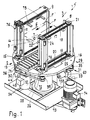
- FIG. 1 illustrates a device 1 for ejecting printed products 3 which are stacked on a table 2 at the end of a stacking shaft 5 and which are indicated in the form of a stack 4 with dash-dotted lines.
- the end of the stacking shaft 5, from which the printed products 3 can be ejected in two opposite directions F consists — viewed in the ejection direction F, F ′ — of two side guide walls 6, 7 lying opposite one another, which do not necessarily have to be constructed with full walls each of which, in the direction of ejection F, has a vertical guide bar 8, 9, together with the opposite one forming a front and a rear shaft boundary; 10, 11 can be driven, the guide strips 8, 9 in the ejection direction F the front shaft limitation and the guide strips 10, 11 the rear shaft limitation respectively.
- a roller table 2 which consists of several conveyor rollers 14 which are freely rotatably mounted one behind the other in a frame 13 transversely to the direction of ejection F, F 'and which forms a flat supporting surface between the guide walls 6, 7 with lateral support rails 15.
- the roller table 2 is on a bogie to be described 16 attached.
- the guide strips 8 to 10, which at least reach the stack height, run around the vertical ends of the guide wall ends viewed in the direction of ejection F, F '.
- the upper and lower ends of a guide bar 8 to 11 are each on an endless toothed belt 17, 18 and. 19, 20 or an articulated chain attached to the driven pulleys 21 to 28 respectively. 21 'to 28' are guided.
- the toothed belts 17 to 20 for the deflection rollers 21 to 28 or 21 ′ which determine the rear stack limitation or the guide strips 8 to 11 forming the front stack limitation. to 28 'arranged on the opposite guide wall 7, 6 (see also Fig.
- the drive devices 29, 30 have a toothed belt transmission 31, 32 and are synchronous, respectively. separately drive-controlled, ie they have drive motors 33, 34 controlled by angle of rotation. 3, the drive devices 29, 30 can also be seen and FIGS. 4 and 5 show the drive device 30 separately.
- a further guide bar 8 'to 11' is attached to each half of its length, so that the following guide bars 8 'to 11' form a stacking shaft after an ejection process.
- a guide wall 6, 7 of the stacking shaft 5 are each at the ends considered in the direction of ejection F, F 'two traction means 17 to 20, respectively, rotating about vertical axes.
- 17 'to 20' arranged, each of which a pair in the upper and lower end region of the guide strips 8 to 11 respectively. 8 'to 11' is provided.
- the traction means 17 to 20 respectively. 17 'to 20' run on pulleys 21 to 28 respectively. 21 'to 28' around.
- the guide strips 8, 9, 10, 11, each forming a front and rear shaft boundary in the direction of ejection F, F ' are drive-connected to both drive devices 29, 30 and can be used synchronously for the ejection process and independently for adjusting the format size in the direction of ejection F, F' , 1 and 2, the deflection rollers 22, 22 'and 26, 26' are firmly connected to the drive shafts 37 ', 38', whereas those with the deflection rollers 22, 22 'and 26, 26' by the traction means 17, 19th , 17 '19' drive-connected deflection rollers 25, 25 'on the shafts 37, 38 are freely rotatable.
- the drive shafts 37, 38 are firmly connected to the deflection rollers 23, 27 and 23 '27', while those with the traction means 18, 20 and. 18 ', 20' drive-connected deflection rollers 24, 28 and 24 '28' are freely rotatably mounted on the drive shafts 37 '38'.
- the deflection rollers 24, 28 and 24 '28' could of course also be connected on the one hand to the drive shafts 37 '38' etc.
- the toothed belt countershaft 31, 32 of the drive devices 29, 30 are on the underside of the bogie 16 by means of bearing supports 35, 36 and about two drive shafts 37, 38, 37 ', 38' of the guide rails 8 which run around two axially opposite axes in the direction of ejection F, F ' to 11 resp. 8 'to 11', with which deflection rollers 39, 40, 39 ', 40' are each drive-connected.
- a toothed belt 41, 42 carrying, freely rotating support rollers 43, 44 are mounted on the bearing supports 35, 36, 35 '36'.
- the drive motors 33, 34 of the toothed belt transmission 31, 32 are attached by an intermediate gear 45, 46 to a support 47 (not visible), 48 connected to the bogie 16.
- the supports 47, 48 are in turn connected to a support frame 49, each of which has a support 50, 51 assigned to a guide wall 6, 7, in which the drive shafts 36, 36 '37, 37' of the guide strips 8 to 11 are mounted and on two guide rods (not shown), which are arranged transversely to the direction of ejection F, F 'and are anchored about the bogie 16, of a guide arrangement are slidably mounted.
- 2 shows bores 53, 53 ', 54, 54', which are penetrated by the guide rods fastened in the bogie 16 for displacing the carriers 50, 51.
- the carriers 50, 51, of the support frame 49 are driven to change or distance from one another by means of a spindle drive 55 in order to change the distance between the guide walls 6, 7.
- a telescopically drivable guide device 56, 57 is provided, each of which consists of two guide parts 58, 59 and 58 '59' which can be pushed together, one of which 58, 58 'has a guide groove for receiving the other.
- the guide parts 58, 59 and 58 ', 59' are connected to the support frame 49 and guide part 58, 58 'is suitable for fastening the supports 47, 48, on which the drive motor 33, 34 of a drive device 29, 30 is suspended, so that the toothed belts 41, 42 remain tensioned by compensation when adjusting the guide walls 6, 7.
- the spindle drive 55 is provided for the adjustment of the guide walls 6, 7 so that there is a uniform lateral distance from the ejection axis of the stack 4 (see FIGS. 1 to 3).
- This consists of a geared motor 60 attached to the bogie 16, with which a shaft 61, which is oriented transversely to the direction of ejection F, F 'and is mounted on the turntable 16, is drive-connected (FIG. 3).
- a pulley 62, 63 is fastened for the lateral adjustment of the guide walls 6, 7 and the stacking shaft 5, which are drive-connected by means of a toothed drive belt or chain 64, 65 to a spindle rod 66, 67 moving the guide walls 6, 7, wherein the spindle rods 66, 67 have oppositely acting threads or a left-hand or right-hand thread. Due to the opposite movements of the guide walls 6, 7 and. Carrier 50, 51 of the support frame 49, the toothed belt 41, 42 guided over a compensation loop remains tensioned.
- the device 1 designed as a stacker, on the underside of which a drum 72 is provided which is fixedly connected to the bogie 16 and is mounted in a machine frame 73 and is drive-connected to a stationary electric motor 74.
- the partial stacks which are alternately piled up by 180 ° to form a stack, can be pressed before being ejected by lifting the roller table 2 against the counterpressure elements 75 which can be displaced into the stacking shaft 5 by the guide walls 6, 7.
- the roller table 2 can be raised and lowered.
- support members 76 are fastened at the top and bottom, which when the stack 4 is ejected from the stacking shaft 5 on the side of the guide walls 6 facing the stack 4 , 7 run.
- the drive shafts 37, 38 'and 37', 38 respectively assigned to a guide wall 6, 7 are each supported at their upper end in a plate 77 connecting the drive shafts.
Abstract
Description
- Fig. 1
- eine räumliche Ansicht einer erfindungsgemässen Einrichtung,
- Fig. 2
- eine vergrösserte räumliche Ansicht der einen Stapel aus Druckerzeugnissen bildenden Vorrichtung der erfindungsgemässen Einrichtung,
- Fig. 3
- eine Draufsicht auf die Vorrichtung gemäss Fig. 2,
- Fig. 4
- eine räumliche Darstellung einer Antriebsvorrichtung einer Vorrichtung zur Bildung eines Stapelschachts und zum Ausstossen des Stapels aus dem Stapelschacht und
- Fig. 5
- eine Draufsicht auf die in Fig. 4 gezeigte Antriebsvorrichtung.
Als Tisch 2 zur Auflage eines Stapels 4 ist ein aus mehreren quer zur Ausstossrichtung F, F' hintereinander in einem Gestell 13 frei drehbar gelagerten Förderrollen 14 gestalteter Rollentisch 2 vorgesehen, der mit seitlichen Stützschienen 15 eine ebene Auflagefläche zwischen den Führungswänden 6, 7 bildet.
Um die umlaufenden Zahnriemen 17 bis 20 resp. 17' bis 20' optimal nutzen zu können, ist auf deren halber Länge jeweils eine weitere Führungsleiste 8' bis 11' befestigt, sodass nach einem Ausstossvorgang die nachfolgenden Führungsleisten 8' bis 11' einen Stapelschacht bilden.
Einer Führungswand 6, 7 des Stapelschachtes 5 sind an den in Ausstossrichtung F, F' betrachteten Enden jeweils zwei um senkrecht stehende Achsen umlaufende Zugmittel 17 bis 20 resp. 17' bis 20' angeordnet, von denen jeweils ein Paar im oberen und unteren Endbereich der Führungsleisten 8 bis 11 resp. 8' bis 11' vorgesehen ist. Die Zugmittel 17 bis 20 resp. 17' bis 20' laufen an Umlenkrollen 21 bis 28 resp. 21' bis 28' um. Die in Ausstossrichtung F, F' jeweils eine vordere und hintere Schachtbegrenzung bildenden Führungsleisten 8, 9, 10, 11 sind mit beiden Antriebsvorrichtungen 29, 30 antriebsverbunden und können synchron für den Ausstossvorgang und unabhängig zur Verstellung der Formatgrösse in Ausstossrichtung F, F' benutzt werden. In den Fig. 1 und 2 sind die Umlenkrollen 22, 22' und 26, 26' mit den Antriebswellen 37', 38' fest verbunden, wogegen die mit den Umlenkrollen 22, 22' und 26, 26' durch die Zugmittel 17, 19, 17' 19' antriebsverbundenen Umlenkrollen 25, 25' an den Wellen 37, 38 frei drehbar gelagert sind. Die Antriebswellen 37, 38 sind mit den Umlenkrollen 23, 27 sowie 23' 27' fest verbunden, während die mit den Zugmitteln 18, 20 resp. 18', 20' antriebsverbundenen Umlenkrollen 24, 28 und 24' 28' an den Antriebswellen 37' 38' frei drehbar gelagert sind.
Die Zahnriemenvorgelege 31, 32 der Antriebsvorrichtungen 29, 30 sind an der Unterseite des Drehgestells 16 mittels Lagersupports 35, 36 und um zwei sich in Ausstossrichtung F, F' quer gegenüberliegenden stehenden Achsen umlaufenden Antriebswellen 37, 38, 37', 38' der Führungsleisten 8 bis 11 resp. 8' bis 11', mit denen Umlenkrollen 39, 40, 39', 40' jeweils antriebsverbunden sind, angeordnet. An den Lagersupports 35, 36, 35' 36' sind einen Zahnriemen 41, 42 tragende, frei drehende Stützrollen 43, 44 gelagert.
Die Antriebsmotoren 33, 34 der Zahnriemenvorgelege 31, 32 sind durch ein Zwischengetriebe 45, 46 an einem mit dem Drehgestell 16 verbundenen Support 47 (nicht sichtbar), 48 hängend befestigt. Die Supports 47, 48 sind ihrerseits mit einem Traggestell 49 verbunden, das jeweils einen einer Führungswand 6, 7 zugeordneten Träger 50, 51 aufweist, in welchen die Antriebswellen 36, 36' 37, 37' der Führungsleisten 8 bis 11 gelagert sind und die an zwei quer zur Ausstossrichtung F, F' angeordneten, um Drehgestell 16 verankerten Führungsstangen (nicht dargestellt) einer Führungsanordnung verschiebbar gelagert sind. Fig. 2 zeigt Bohrungen 53, 53', 54, 54', die von den im Drehgestell 16 befestigten Führungsstangen zur Verschiebung der Träger 50, 51 durchsetzt werden. Die Träger 50, 51, des Traggestells 49 sind zur Aenderung des Abstandes zwischen den Führungswänden 6, 7 über einen Spindelantrieb 55 sich voneinander entfernend oder nähernd angetrieben. Zu diesem Zweck ist eine teleskopisch antreibbare Führungsvorrichtung 56, 57 vorgesehen, die jeweils aus zwei aneinander verschiebbaren Führungsteilen 58, 59 bzw. 58' 59' besteht, von denen das eine 58, 58' eine Führungsnut zur Aufnahme des anderen aufweist. Die Führungsteile 58, 59 bzw. 58', 59' sind mit dem Traggestell 49 verbunden und Führungsteil 58, 58' eignet sich zur Befestigung der Supports 47, 48, an denen der Antriebsmotor 33, 34 einer Antriebsvorrichtung 29, 30 aufgehängt ist, sodass die Zahnriemen 41, 42 durch einen Ausgleich beim Verstellen der Führungswände 6, 7 gespannt bleiben.
Für das Verstellen der Führungswände 6, 7, sodass ein gleichmässiger seitlicher Abstand zur Ausstossachse der Stapel 4 entsteht, ist der Spindelantrieb 55 vorgesehen (siehe Fig. 1 bis 3). Dieser besteht aus einem am Drehgestell 16 befestigten Getriebemotor 60, mit dem eine quer zur Ausstossrichtung F, F' ausgerichtete, am Drehtisch 16 gelagerte Welle 61 antriebsverbunden ist (Fig. 3). An dieser Welle 61 ist für die seitliche Verstellung der Führungswände 6, 7 und des Stapelschachtes 5 jeweils eine Riemenscheibe 62, 63 befestigt, die mittels verzahntem Antriebsriemen oder Kette 64, 65 mit einer die Führungswände 6, 7 bewegenden Spindelstange 66, 67 antriebsverbunden sind, wobei die Spindelstangen 66, 67 gegensätzlich wirkende Gewinde bzw. ein Links- bzw. Rechtsgewinde aufweisen. Durch die entgegengerichteten Bewegungen der Führungswände 6, 7 resp. Träger 50, 51 des Traggestells 49 bleibt der über eine Kompensationsschlaufe geführte Zahnriemen 41, 42 gespannt.
An den von einem sich im Stapelschacht 5 befindenden Stapel 4 aus Druckerzeugnissen 3 abgewandten Seiten der Führungsleisten 8 bis 11 sind jeweils oben und unten Stützorgane 76 befestigt, die beim Ausstossen der Stapel 4 aus dem Stapelschacht 5 auf der dem Stapel 4 zugewandten Seite der Führungswände 6, 7 verlaufen.
Die einer Führungswand 6, 7 jeweils zugeordneten Antriebswellen 37, 38' und 37', 38 sind an ihrem oberen Ende jeweils in einer die Antriebswellen verbindenden Platte 77 gelagert.
Claims (20)
- Einrichtung (1) zum Ausstossen von auf einem Tisch gestapelten Druckerzeugnissen (3) aus einem durch vier Seitenkanten der Druckerzeugnisse (3) bestimmten Stapelschacht (5), dadurch gekennzeichnet, dass der Stapelschacht (5) in Ausstossrichtung (F, F') betrachtet zwei sich gegenüberliegende seitliche Führungswände (6, 7) aufweist, entlang derer jeweils eine, gemeinsam mit der gegenüberliegenden eine vordere und eine hintere Schachtbegrenzung bildende, senkrechte Führungsleiste (8 bis 11 resp. 8' bis 11') antreibbar, und das in Ausstossrichtung (F, F') hintere Führungsleistenpaar (10, 11 resp. 10', 11' bzw. 8, 9 resp. 8', 9') als Ausstossvorrichtung (12) ausgebildet ist.
- Einrichtung nach Anspruch 1, dadurch gekennzeichnet, dass die Führungsleistenpaare (10, 11 resp. 10', 11' bzw. 8, 9 resp. 8', 9') jeweils an um senkrecht stehende Achsen umlaufend angetriebenen, durch Zahnriemen oder Gelenkketten ausgebildeten Zugmitteln (17 bis 20 resp. 17' bis 20') befestigt sind.
- Einrichtung nach Anspruch 2, dadurch gekennzeichnet, dass die Führungsleisten (8 bis 11 resp. 8' bis 11') in Ausstossrichtung (F, F') der vorderen und hinteren Schachtbegrenzung jeweils mit einem oberen und einem unteren Ende an den Zugmitteln (17 bis 20 resp. 17' bis 20') befestigt sind.
- Einrichtung nach Anspruch 3, dadurch gekennzeichnet, dass ein unteres Ende resp. ein oberes Ende einer jeweils für eine vordere oder eine hintere Schachtbegrenzung vorgesehenen Führungsleiste (8 bis 11 resp. 8' bis 11') benachbarte Zugmittel (17 bis 20 resp. 17' bis 20') aufweist.
- Einrichtung nach einem der Ansprüche 1 bis 4, dadurch gekennzeichnet, dass die zur Bildung der vorderen resp. hinteren Schachtbegrenzung bestimmten Führungsleistenpaare (8, 9 resp. 10, 11 resp. 8', 9' resp. 10', 11') jeweils einer Antriebsvorrichtung (29, 30) zugeordnet sind, die synchron oder getrennt antriebsgesteuert sind.
- Einrichtung nach Anspruch 5, dadurch gekennzeichnet, dass an einer eine stehende Achse aufweisenden Antriebswelle (37, 38, 37', 38') jeweils zwei mit der Antriebswelle (37, 38, 37' 38') fest verbundene durch Zugmittel (17 bis 20, 17' bis 20') mit jeweils zwei frei drehbaren Umlenkrollen (24, 28, 24', 28', 21, 25, 21', 25') einer Antriebswelle (37, 38, 37' 38') Umlenkrollen (22, 26, 22', 26'; 23, 27; 23', 27') angeordnet sind.
- Einrichtung nach einem der Ansprüche 2 bis 6, dadurch gekennzeichnet, dass an den für die vordere resp. hintere Schachtbegrenzung vorgesehenen Zugmitteln (17 bis 20 resp. 17' bis 20') jeweils zwei einer Führungswand (6, 7) zugeordnete Führungsleisten (8 bis 11 resp. 8' bis 11') in regelmässigen Abständen befestigt sind.
- Einrichtung nach einem der Ansprüche 2 bis 7, dadurch gekennzeichnet, dass die zur Bildung der vorderen resp. hinteren Schachtbegrenzung entlang den Führungswänden (6, 7) des Stapelschachtes (5) verlaufenden Zugmittel (17 bis 20 resp. 17' bis 20') resp. Führungsleisten (8 bis 11 resp. 8' bis 11') mit jeweils einer der Antriebsvorrichtungen (29, 30) antriebsverbunden sind.
- Einrichtung nach Anspruch 8, dadurch gekennzeichnet, dass den als Ausstossvorrichtung (12) bestimmten Führungsleisten (8 bis 11 resp. 8' bis 11') oder den als vordere Schachtbegrenzung bestimmten Führungsleisten (8 bis 11 resp. 8' bis 11') eine Antriebsvorrichtung (29, 30) zugeordnet ist.
- Einrichtung nach einem der Ansprüche 8 oder 9, dadurch gekennzeichnet, dass die einen Motor (33, 34) aufweisenden Antriebsvorrichtungen (29, 30) als um senkrechte Achsen umlaufende Zahnriemenvorgelege (31, 32) ausgebildet sind.
- Einrichtung nach einem der Ansprüche 2 bis 10, dadurch gekennzeichnet, dass die senkrecht stehenden Achsen der entlang einer Führungswand (6, 7) umlaufenden Führungsleisten (8 bis 11 resp. 8' bis 11') resp. Zugmittel (17 bis 20 resp. 17' bis 20') in Ausstossrichtung (F, F') betrachtet an den Enden der Führungswand (6, 7) angeordnet sind.
- Einrichtung nach Anspruch 10, dadurch gekennzeichnet, dass jeweils zwei quer zur Ausstossrichtung (F, F') sich gegenüberliegende stehende Achsen umlaufender Führungsleisten (8 bis 11 resp. 8' bis 11') einer Antriebsvorrichtung (29, 30) zugeordnet sind.
- Einrichtung nach einem der Ansprüche 8 bis 12, dadurch gekennzeichnet, dass die einer Führungswand (6, 7) jeweils zugeordneten stehenden Achsen zur Aenderung des Abstandes der Führungswände (6, 7) auf einem quer zur Ausstossrichtung (F, F') in einer Führungsanordnung verstellbaren Träger (50, 51) eines Traggestells (49) angeordnet sind.
- Einrichtung nach Anspruch 13, dadurch gekennzeichnet, dass die Träger (50, 51) des Traggestells (49) jeweils mit einem gegensätzlich wirkende Spindelstangen (66, 67) aufweisenden Spindelantrieb (55) antriebsverbunden sind.
- Einrichtung nach einem der Ansprüche 8 bis 14, dadurch gekennzeichnet, dass der Motor (33, 34) einer Antriebsvorrichtung (29, 30) der Führungsleisten (8 bis 11 resp. 8' bis 11') jeweils mit einer an dem Traggestell (49) befestigten und parallel zur Bewegung der Träger (50, 51) teleskopisch ausgebildeten Führungsanordnung verbunden ist.
- Einrichtung nach Anspruch 15, dadurch gekennzeichnet, dass der mit einem Träger (50, 51) des Traggestells (49) verbundene Motor (33, 34) einer Antriebsvorrichtung (29, 30) durch ein mit dem Spindelantrieb (55) verbundenes Vorgelege (64, 65) proportional zu der Abstandsänderung der Führungswände (6, 7) verschiebbar ist.
- Einrichtung nach Anspruch 16, dadurch gekennzeichnet, dass das Traggestell (49) durch die Führungsanordnung an einem um eine senkrechte Achse antreibbaren Drehgestell (16) befestigt ist.
- Einrichtung nach einem der Ansprüche 6 bis 17, dadurch gekennzeichnet, dass der Motor (33, 34) einer Antriebsvorrichtung (29, 30) durch ein Zahnriemenvorgelege (31, 32) mit den sich quer zur Ausstossrichtung (F, F') gegenüberliegenden stehenden Achsen der jeweils für die vordere resp. hintere Schachtbegrenzung bestimmten Zugmittel (17 bis 20 resp. 17' bis 20') bzw. Führungsleisten (8 bis 11 resp. 8' bis 11') antriebsverbunden ist.
- Einrichtung nach Anspruch 18, dadurch gekennzeichnet, dass das Zahnriemenvorgelege (31, 32) mit an den sich quer zur Ausstossrichtung (F, F') gegenüberstehenden Achsen gelagerten Umlenkrollen (39, 40 resp. 39', 40') der Führungsleisten (8 bis 11 resp. 8' bis 11') und an dem Drehgestell (16) gelagerten Rollen (68, 69) resp. Stützrollen (43, 44) antriebsverbunden ist.
- Einrichtung nach einem der Ansprüche 18 und 19, dadurch gekennzeichnet, dass ein Abschnitt eines zwei sich gegenüberstehende Achsen verbindenden Zahnriemens (41, 42) und ein eine stehende Achse mit dem Antriebsrad (71) des Motors (33, 34) verbindender Abschnitt des Zahnriemens (41, 42) eine in Abhängigkeit des Abstandes der Führungswände (6, 7) veränderbare Riemenausgleichsschlaufe (70) bildet.
Priority Applications (7)
| Application Number | Priority Date | Filing Date | Title |
|---|---|---|---|
| EP02405400A EP1362817B1 (de) | 2002-05-17 | 2002-05-17 | Einrichtung zum Ausstossen von auf einem Tisch gestapelten Druckerzeugnissen. |
| DE50211961T DE50211961D1 (de) | 2002-05-17 | 2002-05-17 | Einrichtung zum Ausstossen von auf einem Tisch gestapelten Druckerzeugnissen. |
| DK02405400T DK1362817T3 (da) | 2002-05-17 | 2002-05-17 | Indretning til udstödning af trykte produkter, der er stablet på et bord |
| AT02405400T ATE390377T1 (de) | 2002-05-17 | 2002-05-17 | Einrichtung zum ausstossen von auf einem tisch gestapelten druckerzeugnissen. |
| ES02405400T ES2303543T3 (es) | 2002-05-17 | 2002-05-17 | Dispositivo para expulsar productos impresos apilados sobre una mesa de una caja de apilamiento. |
| US10/440,558 US6966743B2 (en) | 2002-05-17 | 2003-05-15 | Device for pushing a stack of printed products from a table |
| NO20032224A NO20032224L (no) | 2002-05-17 | 2003-05-16 | Innretning for utstöting av på et bord stablede trykksaker |
Applications Claiming Priority (1)
| Application Number | Priority Date | Filing Date | Title |
|---|---|---|---|
| EP02405400A EP1362817B1 (de) | 2002-05-17 | 2002-05-17 | Einrichtung zum Ausstossen von auf einem Tisch gestapelten Druckerzeugnissen. |
Publications (2)
| Publication Number | Publication Date |
|---|---|
| EP1362817A1 true EP1362817A1 (de) | 2003-11-19 |
| EP1362817B1 EP1362817B1 (de) | 2008-03-26 |
Family
ID=8185815
Family Applications (1)
| Application Number | Title | Priority Date | Filing Date |
|---|---|---|---|
| EP02405400A Expired - Lifetime EP1362817B1 (de) | 2002-05-17 | 2002-05-17 | Einrichtung zum Ausstossen von auf einem Tisch gestapelten Druckerzeugnissen. |
Country Status (7)
| Country | Link |
|---|---|
| US (1) | US6966743B2 (de) |
| EP (1) | EP1362817B1 (de) |
| AT (1) | ATE390377T1 (de) |
| DE (1) | DE50211961D1 (de) |
| DK (1) | DK1362817T3 (de) |
| ES (1) | ES2303543T3 (de) |
| NO (1) | NO20032224L (de) |
Cited By (4)
| Publication number | Priority date | Publication date | Assignee | Title |
|---|---|---|---|---|
| EP1445224A1 (de) * | 2003-01-14 | 2004-08-11 | Ferag AG | Vorrichtung zum Bilden von Stapeln aus flächigen Gegenständen |
| EP2133301A1 (de) * | 2008-05-23 | 2009-12-16 | Ferag AG | Drehhubtisch |
| EP2192067A1 (de) | 2008-11-28 | 2010-06-02 | Müller Martini Holding AG | Stapelvorrichtung für Druckprodukte |
| US20130209214A1 (en) * | 2012-02-10 | 2013-08-15 | Illinois Tool Works Inc. | Pusher assembly with dynamic width adjustment for stacker |
Families Citing this family (3)
| Publication number | Priority date | Publication date | Assignee | Title |
|---|---|---|---|---|
| US20060280542A1 (en) * | 2005-05-25 | 2006-12-14 | Thieme Gmbh & Co. Kg | Flatbed printing machine |
| CH705846A1 (de) * | 2011-12-07 | 2013-06-14 | Ferag Ag | Einrichtung und Verfahren zum Zusammenstellen von flächigen Produkten, insbesondere von Druckereiprodukten. |
| US8776983B2 (en) * | 2012-06-26 | 2014-07-15 | Shenzhen China Star Optoelectronics Technology Co., Ltd | Turntable device for substrate and substrate transporting system |
Citations (4)
| Publication number | Priority date | Publication date | Assignee | Title |
|---|---|---|---|---|
| US3532230A (en) * | 1968-04-12 | 1970-10-06 | Cutler Hammer Inc | High speed counter stacker for flexible articles |
| CH567996A5 (en) * | 1973-06-22 | 1975-10-15 | Ferag Ag | Equipment for stacking printed products - has stacking shaft with pushing out devices along two sides |
| US4068567A (en) * | 1977-01-31 | 1978-01-17 | Cutler-Hammer, Inc. | Combined ejector-gate means for rotatable table of an article counter-stacker |
| FR2806396A1 (fr) * | 2000-03-15 | 2001-09-21 | Sarl Serop Concept | Machine pour l'empilage ou le desempilage automatique d'objets plats |
Family Cites Families (9)
| Publication number | Priority date | Publication date | Assignee | Title |
|---|---|---|---|---|
| US3595370A (en) * | 1969-07-03 | 1971-07-27 | Yuji Fujishiro | Apparatus for stacking and transferring bundles of printed sheets in super-high-speed rolling press |
| US3599807A (en) * | 1970-02-02 | 1971-08-17 | Cutler Hammer Inc | Article counter-stacker having mechanically operated gates on the stack-receiving table |
| SE387612B (sv) * | 1975-04-16 | 1976-09-13 | Wamac Ab | Anordning med en uppsamlingskorg for uppsamling av trycksaker i form av en stapel och avlemning av stapeln |
| US4103785A (en) * | 1976-08-18 | 1978-08-01 | Wiseman Raymond L | Apparatus for rotating and discharging articles |
| US4547112A (en) | 1984-01-20 | 1985-10-15 | Rima Enterprises | Signature handling apparatus |
| US4749077A (en) * | 1985-03-01 | 1988-06-07 | Quipp, Incorporated | Pusher assembly for a turntable employing plural stepper motors |
| AU581609B2 (en) * | 1986-02-17 | 1989-02-23 | Gunze Limited | Apparatus for handling signatures before binding |
| US5433582A (en) * | 1994-06-14 | 1995-07-18 | Medina; Pete R. | Device for discharging papers |
| EP1273542B1 (de) * | 2001-07-05 | 2006-05-31 | Grapha-Holding AG | Einrichtung zum Transport von auf einer Auflage in einem Stapel aufeinanderliegenden Druckprodukten |
-
2002
- 2002-05-17 AT AT02405400T patent/ATE390377T1/de active
- 2002-05-17 DE DE50211961T patent/DE50211961D1/de not_active Expired - Lifetime
- 2002-05-17 EP EP02405400A patent/EP1362817B1/de not_active Expired - Lifetime
- 2002-05-17 ES ES02405400T patent/ES2303543T3/es not_active Expired - Lifetime
- 2002-05-17 DK DK02405400T patent/DK1362817T3/da active
-
2003
- 2003-05-15 US US10/440,558 patent/US6966743B2/en not_active Expired - Fee Related
- 2003-05-16 NO NO20032224A patent/NO20032224L/no not_active Application Discontinuation
Patent Citations (4)
| Publication number | Priority date | Publication date | Assignee | Title |
|---|---|---|---|---|
| US3532230A (en) * | 1968-04-12 | 1970-10-06 | Cutler Hammer Inc | High speed counter stacker for flexible articles |
| CH567996A5 (en) * | 1973-06-22 | 1975-10-15 | Ferag Ag | Equipment for stacking printed products - has stacking shaft with pushing out devices along two sides |
| US4068567A (en) * | 1977-01-31 | 1978-01-17 | Cutler-Hammer, Inc. | Combined ejector-gate means for rotatable table of an article counter-stacker |
| FR2806396A1 (fr) * | 2000-03-15 | 2001-09-21 | Sarl Serop Concept | Machine pour l'empilage ou le desempilage automatique d'objets plats |
Cited By (7)
| Publication number | Priority date | Publication date | Assignee | Title |
|---|---|---|---|---|
| EP1445224A1 (de) * | 2003-01-14 | 2004-08-11 | Ferag AG | Vorrichtung zum Bilden von Stapeln aus flächigen Gegenständen |
| EP2133301A1 (de) * | 2008-05-23 | 2009-12-16 | Ferag AG | Drehhubtisch |
| EP2192067A1 (de) | 2008-11-28 | 2010-06-02 | Müller Martini Holding AG | Stapelvorrichtung für Druckprodukte |
| US8573920B2 (en) | 2008-11-28 | 2013-11-05 | Mueller Martini Holding Ag | Stacking device for print products |
| CN101746637B (zh) * | 2008-11-28 | 2015-06-03 | 米勒·马蒂尼控股公司 | 用于印刷制品的堆垛装置 |
| US20130209214A1 (en) * | 2012-02-10 | 2013-08-15 | Illinois Tool Works Inc. | Pusher assembly with dynamic width adjustment for stacker |
| US9181061B2 (en) * | 2012-02-10 | 2015-11-10 | Signode Industrial Group Llc | Pusher assembly with dynamic width adjustment for stacker |
Also Published As
| Publication number | Publication date |
|---|---|
| US20030215322A1 (en) | 2003-11-20 |
| DE50211961D1 (de) | 2008-05-08 |
| US6966743B2 (en) | 2005-11-22 |
| ES2303543T3 (es) | 2008-08-16 |
| ATE390377T1 (de) | 2008-04-15 |
| EP1362817B1 (de) | 2008-03-26 |
| DK1362817T3 (da) | 2008-07-28 |
| NO20032224L (no) | 2003-11-18 |
| NO20032224D0 (no) | 2003-05-16 |
Similar Documents
| Publication | Publication Date | Title |
|---|---|---|
| EP0623542B1 (de) | Einrichtung zur Bildung eines sich senkrecht zu den stehend aneinandergereihten Druckbogen erstreckenden Stapels | |
| DE19946531C2 (de) | Senkrechtförderer für eine Palettiervorrichtung | |
| DE2638691C2 (de) | Vorrichtung zum Stapeln von einzelnen oder in kleinen Paketen flachliegend zugeführten Tafeln aus z.B. Wellpappe | |
| DE3107437C2 (de) | ||
| DD140132A5 (de) | Vorrichtung zum beschicken einer packmaschine mit suesswaren | |
| CH671945A5 (de) | ||
| EP1445224B1 (de) | Vorrichtung zum Bilden von Stapeln aus flächigen Gegenständen | |
| EP1362817B1 (de) | Einrichtung zum Ausstossen von auf einem Tisch gestapelten Druckerzeugnissen. | |
| DE10118813C2 (de) | Vorrichtung zum Abstapeln von Faltschachtelschläuchen | |
| DE202005014323U1 (de) | Vorrichtung zum Stapeln von Dachpfannen | |
| EP1104650B1 (de) | Langroller zum Langrollen von Teigstücken | |
| DE2519341A1 (de) | Vorrichtung zum beladen mehrerer tragplatten eines ablegegestells mit blattartigen gegenstaenden | |
| DE2547114A1 (de) | Verfahren und vorrichtung zum ueberfuehren von staeben von einer streckbank zu einem foerderer | |
| DE2730102C3 (de) | Vorrichtung zum Aufklappen der beiden nach dem Trennen noch Rücken an Rücken stehenden keramischen Einzelplatten einer gemeinsam gebrannten Doppelplatte, derart, daß die Sichtflächen nach oben zu liegen kommen | |
| EP0822739A2 (de) | Automatisierte Vorrichtung zum Prüfen von Leiterplatten | |
| DE2416624A1 (de) | Verteilvorrichtung fuer geschnittene, scheibenfoermige produkte | |
| DE2428238C3 (de) | Vorrichtung zum Palettieren von Stückgütern, insbesondere von Fässern | |
| DE2107686C3 (de) | Bogenausleger zum Bilden eines Stapels von aufeinanderliegender! Bogen | |
| DE1945419C3 (de) | Einrichtung zum Beladen der Tragböden von Traggestellen mit Ziegelformlingen tragenden Paletten | |
| DE2403209C3 (de) | Kontinuierlich arbeitende Presse zum Herstellen von Platten, wie Span-, Faserplatten o.dgl | |
| DE2262019C3 (de) | Einrichtung zum Besetzen von Traglatten mit keramischen Formungen | |
| DE1756324A1 (de) | Der kontinuierlichen Abnahme einzelner Bogen oder Platten von Stapeln oder der kontinuierlichen Zufuehrung einzelner Bogen oder Platten auf Stapel dienende Stapelhubvorrichtung | |
| EP0691295A1 (de) | Plattenbeschickungseinrichtung für Plattenaufteilsägen | |
| DE2556975B2 (de) | Stapelvorrichtung | |
| DE2250536A1 (de) | Verfahren und maschine zum stapeln und entstapeln grosser plattenfoermiger werkstuecke |
Legal Events
| Date | Code | Title | Description |
|---|---|---|---|
| PUAI | Public reference made under article 153(3) epc to a published international application that has entered the european phase |
Free format text: ORIGINAL CODE: 0009012 |
|
| AK | Designated contracting states |
Kind code of ref document: A1 Designated state(s): AT BE CH CY DE DK ES FI FR GB GR IE IT LI LU MC NL PT SE TR |
|
| AX | Request for extension of the european patent |
Extension state: AL LT LV MK RO SI |
|
| 17P | Request for examination filed |
Effective date: 20040426 |
|
| AKX | Designation fees paid |
Designated state(s): AT BE CH CY DE DK ES FI FR GB GR IE IT LI LU MC NL PT SE TR |
|
| GRAP | Despatch of communication of intention to grant a patent |
Free format text: ORIGINAL CODE: EPIDOSNIGR1 |
|
| GRAS | Grant fee paid |
Free format text: ORIGINAL CODE: EPIDOSNIGR3 |
|
| GRAA | (expected) grant |
Free format text: ORIGINAL CODE: 0009210 |
|
| AK | Designated contracting states |
Kind code of ref document: B1 Designated state(s): AT BE CH CY DE DK ES FI FR GB GR IE IT LI LU MC NL PT SE TR |
|
| REG | Reference to a national code |
Ref country code: GB Ref legal event code: FG4D Free format text: NOT ENGLISH |
|
| REG | Reference to a national code |
Ref country code: IE Ref legal event code: FG4D Free format text: LANGUAGE OF EP DOCUMENT: GERMAN Ref country code: CH Ref legal event code: EP |
|
| REF | Corresponds to: |
Ref document number: 50211961 Country of ref document: DE Date of ref document: 20080508 Kind code of ref document: P |
|
| REG | Reference to a national code |
Ref country code: SE Ref legal event code: TRGR |
|
| REG | Reference to a national code |
Ref country code: DK Ref legal event code: T3 |
|
| PG25 | Lapsed in a contracting state [announced via postgrant information from national office to epo] |
Ref country code: FI Free format text: LAPSE BECAUSE OF FAILURE TO SUBMIT A TRANSLATION OF THE DESCRIPTION OR TO PAY THE FEE WITHIN THE PRESCRIBED TIME-LIMIT Effective date: 20080326 |
|
| REG | Reference to a national code |
Ref country code: ES Ref legal event code: FG2A Ref document number: 2303543 Country of ref document: ES Kind code of ref document: T3 |
|
| ET | Fr: translation filed | ||
| REG | Reference to a national code |
Ref country code: IE Ref legal event code: FD4D |
|
| PG25 | Lapsed in a contracting state [announced via postgrant information from national office to epo] |
Ref country code: PT Free format text: LAPSE BECAUSE OF FAILURE TO SUBMIT A TRANSLATION OF THE DESCRIPTION OR TO PAY THE FEE WITHIN THE PRESCRIBED TIME-LIMIT Effective date: 20080901 |
|
| PG25 | Lapsed in a contracting state [announced via postgrant information from national office to epo] |
Ref country code: MC Free format text: LAPSE BECAUSE OF NON-PAYMENT OF DUE FEES Effective date: 20080531 |
|
| PG25 | Lapsed in a contracting state [announced via postgrant information from national office to epo] |
Ref country code: IE Free format text: LAPSE BECAUSE OF FAILURE TO SUBMIT A TRANSLATION OF THE DESCRIPTION OR TO PAY THE FEE WITHIN THE PRESCRIBED TIME-LIMIT Effective date: 20080326 |
|
| PLBE | No opposition filed within time limit |
Free format text: ORIGINAL CODE: 0009261 |
|
| STAA | Information on the status of an ep patent application or granted ep patent |
Free format text: STATUS: NO OPPOSITION FILED WITHIN TIME LIMIT |
|
| 26N | No opposition filed |
Effective date: 20081230 |
|
| PG25 | Lapsed in a contracting state [announced via postgrant information from national office to epo] |
Ref country code: CY Free format text: LAPSE BECAUSE OF FAILURE TO SUBMIT A TRANSLATION OF THE DESCRIPTION OR TO PAY THE FEE WITHIN THE PRESCRIBED TIME-LIMIT Effective date: 20080326 |
|
| PG25 | Lapsed in a contracting state [announced via postgrant information from national office to epo] |
Ref country code: LU Free format text: LAPSE BECAUSE OF NON-PAYMENT OF DUE FEES Effective date: 20080517 |
|
| PG25 | Lapsed in a contracting state [announced via postgrant information from national office to epo] |
Ref country code: TR Free format text: LAPSE BECAUSE OF FAILURE TO SUBMIT A TRANSLATION OF THE DESCRIPTION OR TO PAY THE FEE WITHIN THE PRESCRIBED TIME-LIMIT Effective date: 20080326 |
|
| PG25 | Lapsed in a contracting state [announced via postgrant information from national office to epo] |
Ref country code: GR Free format text: LAPSE BECAUSE OF FAILURE TO SUBMIT A TRANSLATION OF THE DESCRIPTION OR TO PAY THE FEE WITHIN THE PRESCRIBED TIME-LIMIT Effective date: 20080627 |
|
| PGFP | Annual fee paid to national office [announced via postgrant information from national office to epo] |
Ref country code: FR Payment date: 20110607 Year of fee payment: 10 Ref country code: ES Payment date: 20110518 Year of fee payment: 10 |
|
| PGFP | Annual fee paid to national office [announced via postgrant information from national office to epo] |
Ref country code: AT Payment date: 20110526 Year of fee payment: 10 Ref country code: BE Payment date: 20110531 Year of fee payment: 10 Ref country code: NL Payment date: 20110531 Year of fee payment: 10 |
|
| BERE | Be: lapsed |
Owner name: MULLER MARTINI HOLDING A.G. Effective date: 20120531 |
|
| REG | Reference to a national code |
Ref country code: NL Ref legal event code: V1 Effective date: 20121201 |
|
| REG | Reference to a national code |
Ref country code: AT Ref legal event code: MM01 Ref document number: 390377 Country of ref document: AT Kind code of ref document: T Effective date: 20120517 |
|
| PG25 | Lapsed in a contracting state [announced via postgrant information from national office to epo] |
Ref country code: AT Free format text: LAPSE BECAUSE OF NON-PAYMENT OF DUE FEES Effective date: 20120517 |
|
| PG25 | Lapsed in a contracting state [announced via postgrant information from national office to epo] |
Ref country code: BE Free format text: LAPSE BECAUSE OF NON-PAYMENT OF DUE FEES Effective date: 20120531 |
|
| REG | Reference to a national code |
Ref country code: FR Ref legal event code: ST Effective date: 20130131 |
|
| PG25 | Lapsed in a contracting state [announced via postgrant information from national office to epo] |
Ref country code: NL Free format text: LAPSE BECAUSE OF NON-PAYMENT OF DUE FEES Effective date: 20121201 |
|
| PG25 | Lapsed in a contracting state [announced via postgrant information from national office to epo] |
Ref country code: FR Free format text: LAPSE BECAUSE OF NON-PAYMENT OF DUE FEES Effective date: 20120531 |
|
| REG | Reference to a national code |
Ref country code: ES Ref legal event code: FD2A Effective date: 20131030 |
|
| PG25 | Lapsed in a contracting state [announced via postgrant information from national office to epo] |
Ref country code: ES Free format text: LAPSE BECAUSE OF NON-PAYMENT OF DUE FEES Effective date: 20120518 |
|
| PGFP | Annual fee paid to national office [announced via postgrant information from national office to epo] |
Ref country code: SE Payment date: 20150516 Year of fee payment: 14 Ref country code: DE Payment date: 20150521 Year of fee payment: 14 Ref country code: DK Payment date: 20150516 Year of fee payment: 14 Ref country code: GB Payment date: 20150518 Year of fee payment: 14 |
|
| PGFP | Annual fee paid to national office [announced via postgrant information from national office to epo] |
Ref country code: IT Payment date: 20150527 Year of fee payment: 14 |
|
| PGFP | Annual fee paid to national office [announced via postgrant information from national office to epo] |
Ref country code: CH Payment date: 20150821 Year of fee payment: 14 |
|
| REG | Reference to a national code |
Ref country code: DE Ref legal event code: R119 Ref document number: 50211961 Country of ref document: DE |
|
| REG | Reference to a national code |
Ref country code: CH Ref legal event code: PL |
|
| REG | Reference to a national code |
Ref country code: DK Ref legal event code: EBP Effective date: 20160531 |
|
| GBPC | Gb: european patent ceased through non-payment of renewal fee |
Effective date: 20160517 |
|
| PG25 | Lapsed in a contracting state [announced via postgrant information from national office to epo] |
Ref country code: CH Free format text: LAPSE BECAUSE OF NON-PAYMENT OF DUE FEES Effective date: 20160531 Ref country code: LI Free format text: LAPSE BECAUSE OF NON-PAYMENT OF DUE FEES Effective date: 20160531 |
|
| PG25 | Lapsed in a contracting state [announced via postgrant information from national office to epo] |
Ref country code: IT Free format text: LAPSE BECAUSE OF NON-PAYMENT OF DUE FEES Effective date: 20160517 Ref country code: SE Free format text: LAPSE BECAUSE OF NON-PAYMENT OF DUE FEES Effective date: 20160518 |
|
| PG25 | Lapsed in a contracting state [announced via postgrant information from national office to epo] |
Ref country code: DE Free format text: LAPSE BECAUSE OF NON-PAYMENT OF DUE FEES Effective date: 20161201 |
|
| PG25 | Lapsed in a contracting state [announced via postgrant information from national office to epo] |
Ref country code: DK Free format text: LAPSE BECAUSE OF NON-PAYMENT OF DUE FEES Effective date: 20160531 Ref country code: GB Free format text: LAPSE BECAUSE OF NON-PAYMENT OF DUE FEES Effective date: 20160517 |