EP2192067A1 - Stapelvorrichtung für Druckprodukte - Google Patents
Stapelvorrichtung für Druckprodukte Download PDFInfo
- Publication number
- EP2192067A1 EP2192067A1 EP08405293A EP08405293A EP2192067A1 EP 2192067 A1 EP2192067 A1 EP 2192067A1 EP 08405293 A EP08405293 A EP 08405293A EP 08405293 A EP08405293 A EP 08405293A EP 2192067 A1 EP2192067 A1 EP 2192067A1
- Authority
- EP
- European Patent Office
- Prior art keywords
- ejection
- stack
- stacking device
- elements
- lift
- Prior art date
- Legal status (The legal status is an assumption and is not a legal conclusion. Google has not performed a legal analysis and makes no representation as to the accuracy of the status listed.)
- Granted
Links
Images
Classifications
-
- B—PERFORMING OPERATIONS; TRANSPORTING
- B65—CONVEYING; PACKING; STORING; HANDLING THIN OR FILAMENTARY MATERIAL
- B65H—HANDLING THIN OR FILAMENTARY MATERIAL, e.g. SHEETS, WEBS, CABLES
- B65H31/00—Pile receivers
- B65H31/30—Arrangements for removing completed piles
- B65H31/3081—Arrangements for removing completed piles by acting on edge of the pile for moving it along a surface, e.g. by pushing
-
- B—PERFORMING OPERATIONS; TRANSPORTING
- B65—CONVEYING; PACKING; STORING; HANDLING THIN OR FILAMENTARY MATERIAL
- B65H—HANDLING THIN OR FILAMENTARY MATERIAL, e.g. SHEETS, WEBS, CABLES
- B65H2301/00—Handling processes for sheets or webs
- B65H2301/40—Type of handling process
- B65H2301/42—Piling, depiling, handling piles
- B65H2301/421—Forming a pile
- B65H2301/4211—Forming a pile of articles alternatively overturned, or swivelled from a certain angle
- B65H2301/42112—Forming a pile of articles alternatively overturned, or swivelled from a certain angle swivelled from 180°
-
- B—PERFORMING OPERATIONS; TRANSPORTING
- B65—CONVEYING; PACKING; STORING; HANDLING THIN OR FILAMENTARY MATERIAL
- B65H—HANDLING THIN OR FILAMENTARY MATERIAL, e.g. SHEETS, WEBS, CABLES
- B65H2301/00—Handling processes for sheets or webs
- B65H2301/40—Type of handling process
- B65H2301/42—Piling, depiling, handling piles
- B65H2301/422—Handling piles, sets or stacks of articles
- B65H2301/4223—Pressing piles
-
- B—PERFORMING OPERATIONS; TRANSPORTING
- B65—CONVEYING; PACKING; STORING; HANDLING THIN OR FILAMENTARY MATERIAL
- B65H—HANDLING THIN OR FILAMENTARY MATERIAL, e.g. SHEETS, WEBS, CABLES
- B65H2301/00—Handling processes for sheets or webs
- B65H2301/40—Type of handling process
- B65H2301/42—Piling, depiling, handling piles
- B65H2301/422—Handling piles, sets or stacks of articles
- B65H2301/4226—Delivering, advancing piles
- B65H2301/42266—Delivering, advancing piles by acting on edge of the pile for moving it along a surface, e.g. pushing
-
- B—PERFORMING OPERATIONS; TRANSPORTING
- B65—CONVEYING; PACKING; STORING; HANDLING THIN OR FILAMENTARY MATERIAL
- B65H—HANDLING THIN OR FILAMENTARY MATERIAL, e.g. SHEETS, WEBS, CABLES
- B65H2402/00—Constructional details of the handling apparatus
- B65H2402/30—Supports; Subassemblies; Mountings thereof
- B65H2402/35—Supports; Subassemblies; Mountings thereof rotating around an axis
- B65H2402/351—Turntables
-
- B—PERFORMING OPERATIONS; TRANSPORTING
- B65—CONVEYING; PACKING; STORING; HANDLING THIN OR FILAMENTARY MATERIAL
- B65H—HANDLING THIN OR FILAMENTARY MATERIAL, e.g. SHEETS, WEBS, CABLES
- B65H2511/00—Dimensions; Position; Numbers; Identification; Occurrences
- B65H2511/10—Size; Dimensions
Definitions
- the invention relates to a stacking device for printed products, with a table on which the printed products are stackable and with at least two ejection organs, each of which can be applied to a stack forming on the table and with which the stack formed by the table is wegschiebbar, and drive members for moving the two ejection organs.
- a stacking device of this kind is known in the art by the US 5,868,548 known.
- This has on a rotatable table two endless circulating chains, where each two finger-like upwardly projecting ejection elements are attached.
- the stack By simultaneously moving a respective ejector of both chains, the stack can be pushed away from the table and ejected. Since the stack rests simultaneously on ejection two ejectors, twisting the stack on the table should be avoided.
- the two chains are driven by a common motor and move synchronously when ejected.
- US 5,338,149 discloses a stacking device with only one ejection member acting on a stack, which is attached to two superimposed chains. Another stacking device, which also has only one acting on a stack ejection member which is mounted on two superimposed circulating chains, is from the US 4,103,785 known. Other stacking devices are from the EP-A-0 829 441 and EP-A-1 362 817 have become known to the applicant. However, these devices having a stack lift require manual intervention during the format change.
- the invention is based on the object to provide a stacking device of the type mentioned, which allows a shorter cycle time of the ejection process and a simpler adaptation to different formats of the printed products.
- the object is achieved according to claim 1 in a generic stacking device in that the two ejection elements are independently movable. Due to this, the distance between these ejection members can be adjusted continuously to adapt to different back lengths of the printed products. Since the two ejection elements are movable independently of each other, the ejector can be accelerated during ejection and thus faster than previously removed from its original position from the stack and placed in a new starting position, which corresponds to the original starting position of the ejection, trailing ejection member. As a result, a new batch or a new package can be formed earlier than previously. In addition, an ejection in any direction but also an unplanned change of the ejector without lengthening the cycle time is possible.
- the table is rotatable and that the two ejection elements are arranged rotatable with the table. This makes it possible to form a stack of several, each rotated by 180 ° to each other arranged layers of printed products.
- the advantages mentioned with regard to the shorter cycle time and the adaptation to different back lengths are retained here.
- both drive members are each driven by a separate motor.
- the two engines are for example Servo motors, each driving an endless drive member, such as a link chain. This allows for precise control and rapid changes of direction, so that the stack can also be pushed away from the table in opposite ejection directions.
- a particularly short cycle time can be achieved if, according to a further development of the invention, a first ejection element is reversingly driven and a second ejection element is rotatably driven to displace a stack.
- the first ejection member is thus brought back to a starting position after the removal of the stack by reversing the direction of movement, which corresponds to the original starting position of the second ejection member.
- the second ejection member which is removed from the stack when ejected, is guided around the stack and brought into the already described new starting position, which corresponds to the original starting position of the first ejection member. This can be significantly shortened for the first ejector the way to a new starting position, which is why both ejection organs are ready to expel faster. If the stack pushed away in the opposite ejection direction of the table, take over the two ejection organs each have the other function.
- the two ejection organs serve to limit the back length of the stack.
- the back length of the stack can be changed by appropriate positioning of the two ejection elements.
- a lift is arranged, with which a stack can be pressed off vertically against at least one press plate.
- the stack can be compressed and pressed at the individual printed products of a stack of rabbet, which is advantageous for further processing.
- the table is format variable for adaptation to different format widths.
- the table has two outer lift plates, which are adjustable transversely to the ejection direction. At these two outer lift plates each preferably a side wall is arranged as a limiting element. This allows adaptation to different format widths. The adaptation to different back lengths is done as mentioned by appropriate positioning of the two ejection elements.
- the table has two inner, fixed lift plates, between which the two ejection elements are movable. This ensures a secure support of the stack and in particular a pressing of the stack.
- the division into inner and outer lift plates and the mobility of the outer lift plates has the consequence that when changing format advantageously no manual intervention is required.
- a guide member is arranged, in which the ejection elements, at least in a section in which a stack is pushed, are guided substantially linear. This can be done by means of rollers or a sliding guide. In this way, advantageously a compact power transmission is realized without further components.
- the two ejection elements are each fastened to an endless drive element, for example a link chain, which are respectively guided around the stack to be ejected, preferably semicircular segment-shaped in a common and substantially horizontal plane and thus form a preferably semicircular segment-shaped path along which at least one ejection element is movable.
- the ejection elements can each be attached to two or more than two superimposed drive members.
- Each ejection member preferably has an ejection finger.
- the two ejection elements can also each have more than one, for example two ejection fingers.
- the stacking device according to the invention is preferably provided for a stacker. But there are also other applications conceivable here. Further advantageous features emerge from the dependent claims, the following description and the drawings.
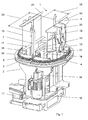
- the in the FIGS. 1 and 2 shown stacking device 1 has a frame 2, which has a substantially horizontal table 3, on which two endless drive members 4, 5 are mounted.
- a lift 12 is arranged, which has two inner lift plates 13 and two outer lift plates 14.
- the lift 12 allows a reduction in the drop height of the printed products 9.
- the stack 8 may consist of several layers of printed products 9, which are each rotated by 180 ° to each other.
- the table 3 can be rotated by means of an actuating cylinder 11 about a vertical axis. This is called so-called crosslapping and is well known to those skilled in the art.
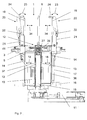
- a stack formed in this way 8 can be pressed by a lift of the lift 12 against pressing flaps 20, that is compacted.
- FIG. 2 are two on or swing at serving for format setting of the stack 8 limiting elements 19 arranged press flaps 20 shown.
- a pivoted, active position is shown on the left side of the drawing.
- For pressing the press flaps 20 are pivoted by means of actuating cylinder 21 in the direction of the arrow 23, respectively.
- the actuating cylinder 21 engage with retractable piston rods 22 each on a compression flap 20.
- each press flap 20 protrudes inward with a press plate 24 via the respective limiting element 19, so that the stack 8 to be squeezed out can be applied against the two press plates 24 by appropriately raising the lift 12.
- the lift 12 is again in the in the FIGS. 1 and 2 Shut down rest position shown.
- the two inner lift plates 13 are arranged at a distance from one another, so that there is a linear passage 33 between them. These inner lift plates 13 are respectively arranged on vertically extending plates 37, which are connected to a driver 15.
- the outer lift plates 14 also have downwardly extending plates 36 which are slidably mounted on a horizontally extending guide 16 and a vertically extending guide 17.
- the inner lift plates 13 can only be moved vertically, while the outer lift plates 14 can be moved both vertically and horizontally.
- the horizontal movement makes it possible to change the distance indicated by double arrows 18 between the two outer lift plates 14.
- By adjusting the outer lift plates 14 at the same time attached to this limiting elements 19 are adjusted. These limiting elements 19 are plate-shaped and extend beyond the table 3 also upwards.
- FIG. 1 indicated format width 26 are set.
- the outer lift plates 14 are adjusted together with the limiting elements 19 accordingly.
- the adjustment can take place via actuators, not shown here and by means of a control, not shown here.
- the drive member 4 is driven by an engine 10 via a transmission 38.
- the engagement on the drive member 4 takes place for example via a in Fig. 3a indicated drive wheel 30. This is stored in table 3.
- the drive member 5 is driven by a further motor, not shown here, which, like the engine 10, has a transmission.
- the engagement also preferably takes place via a drive wheel 30.
- the two drive elements 4, 5 are designed as link chains, but other endless drive elements are also conceivable here. Both drive elements 4, 5 are each a deflection wheel 29 ( Fig. 3a ) and form in plan view essentially a semicircle segment.
- a first ejection member 6 is fixed, which is rod-shaped or finger-shaped and protrudes vertically from the table 3 upwards.
- a second ejection member 7 is fixed, which is formed substantially the same as the ejection member 6.
- the distance between the two ejection members 6, 7 determines the in FIG. 1 indicated back length 25 of a stack to be ejected 8. Since the two drive members 4, 5 are driven independently of each other, the distance between the two ejection members 6, 7 can be adjusted continuously. The adjustment takes place via the two aforementioned motors 10 which are connected to a controller, not shown here.
- the passage 33 between the two inner lift plates 13 is so far that the two ejection elements 6, 7 can pass through this passage 33.
- the two ejection organs 6, 7 according to FIG. 2 each guided with a sliding guide 28 linearly in a guide rail 27 formed as a guide rail, which extends horizontally and rectilinearly in the plane of the table 3.
- a guide rail 27 formed as a guide rail, which extends horizontally and rectilinearly in the plane of the table 3.
- the ejection elements 6, 7 are each attached to two or more superposed drive members.
- the two ejection elements 6, 7 each have not one, but two or more than two upwardly projecting rods or fingers or in which more than one ejection member to a drive member 4, 5 is fixed. If the table 3 is rotated about a vertical axis by 180 °, as mentioned above, then the ejection elements 6, 7 rotate accordingly.
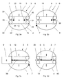
- the ejection is described below on the basis of FIGS. 3a to 3d explained in more detail.
- FIG. 3a schematically shows a plan view of the table 3 on which a stack 8 is formed.
- This stack 8 is located between two limiting elements 19 and between the first ejection element 6 and the second ejection element 7.
- the distances between the two limiting elements 19 and between the two ejection elements 6, 7 correspond to the format of the stack 8 or its back length 25 and format width 26
- Double arrows 34 indicate the adjustability of the limiting elements 19.
- the first ejection member 6 is connected to the drive member 5 and the second ejection member 7 to the drive member 4.
- These drive members 4, 5 are arranged as shown approximately semicircular segmented and each have a substantial straight track section 31 and a curved track section 32.
- the straight track sections 31 form the passage 33.
- the curved track sections 32 may also have a different shape to the ejected stack 8 running around, for example, formed with rounded corners rectangular or elliptical path.
- the two ejection elements 6, 7 are within the passage 33 and the stack 8 is ready for ejection.
- the lift 12 is located in the FIGS. 1 and 2 shown lower position.
- the first ejection member 7 limiting the back length 25 of the stack 8, with the drive member 4 is removed from the stack 8, as shown drives out of the passage 33 and is laterally guided in the curved path portion 32 of the drive member 4.
- the first ejection element 6 starts the stack 8 in an ejection direction 39, ie to eject to the left and is thus in the FIG. 3b moved to the left.
- the second ejection member 7 is located on the curved path section 32, for example in the in Figure 3c shown position. Meanwhile, the first ejector 6, the stack 8 according to Figure 3c already largely expelled. In this ejection movement of the stack 8 is guided between the two limiting elements 19. The first ejection member 6 moves from the illustration in FIG Figure 3c even further to the left and pushes the stack 8 in the ejection direction 39 completely from the table 3, so that the stack 8 can be taken for example by a transport device, not shown here. The second ejection member 7 is now in the in 3d figure shown position, which that of the first ejection member 6 according to FIG. 3a equivalent.
- the first ejection member 6 is by reversing its direction of movement by the drive member 5 in the in 3d figure shown position. This position corresponds to that of the second ejection member 7 according to FIG. 3a , To move the first ejection member 6 in the in 3d figure shown position, the drive member 5 is thus driven reversing. When ejecting the drive member 4 is always moved in the same direction. The drive member 5, however, is first moved counterclockwise in the clockwise direction and after the ejection of the stack 8.
- the ejection of the stack 8 thus takes place according to the FIGS. 3a to 3c from right to left. But it is also possible to eject from left to right, in which case the ejection organs 6, 7 each take over the other function.
- the possible ejection directions 39, 40 are shown, It is essential as can be seen that the two drive members 4, 5 can be moved independently controlled. Each of the two ejection elements 6, 7 can thus be moved at different speeds and also the direction of movement can be changed at any time. Accordingly, the distance between the two ejection elements 6, 7 can be adjusted by appropriate movements of the drive members 4, 5.
- the main advantages here are a shorter cycle time when ejecting and the possible adaptation to different back lengths by corresponding adjustment of the two ejection elements 6, 7.
Landscapes
- Engineering & Computer Science (AREA)
- Mechanical Engineering (AREA)
- Pile Receivers (AREA)
- Forming Counted Batches (AREA)
Abstract
Description
- Die Erfindung betrifft eine Stapelvorrichtung für Druckprodukte, mit einem Tisch, auf dem die Druckprodukte stapelbar sind und mit wenigstens zwei Ausstossorganen, die jeweils an einen sich auf dem Tisch bildenden Stapel anlegbar sind und mit denen der gebildete Stapel vom Tisch wegschiebbar ist, und mit Antriebsorganen zum Bewegen der beiden Ausstossorgane.
- Eine Stapelvorrichtung dieser Art ist im Stand der Technik durch die
US 5,868,548 bekannt geworden. Diese besitzt auf einem drehbaren Tisch zwei endlos umlaufende Ketten, an denen jeweils zwei fingerartig nach oben ragende Ausstossorgane befestigt sind. Durch gleichzeitiges Bewegen jeweils eines Ausstossorgäns beider Ketten kann der Stapel vom Tisch weggeschoben und ausgestossen werden. Da der Stapel beim Ausstossen gleichzeitig an zwei Ausstossorganen anliegt, soll ein Verdrehen des Stapels auf dem Tisch vermieden werden. Die beiden Ketten werden durch einen gemeinsamen Motor angetrieben und bewegen sich beim Ausstossen synchron zueinander. -
US 5,338,149 offenbart eine Stapelvorrichtung mit lediglich einem auf einen Stapel einwirkenden Ausstossorgan, das an zwei übereinander umlaufende Ketten befestigt ist. Eine weitere Stapelvorrichtung, die ebenfalls lediglich ein auf einen Stapel einwirkendes Ausstossorgan aufweist, das an zwei übereinander umlaufenden Ketten montiert ist, ist aus derUS 4,103,785 bekannt geworden. Weitere Stapelvorrichtungen sind aus derEP-A-0 829 441 undEP-A-1 362 817 des Anmelders bekannt geworden. Diese einen Stapellift aufweisenden Vorrichtungen erfordern jedoch beim Formatwechsel manuelle Eingriffe. - Bei bekannten Stapelvorrichtungen ist insbesondere nachteilig, dass die Rückenlänge der zu stapelnden Druckprodukte, d.h. des jeweiligen Stapels, durch verstellbare Klappen begrenzt wird, die geöffnet und geschlossen werden müssen, was einerseits eine hohe Belastung bedeutet und anderseits die Zykluszeit verlängert.
- Der Erfindung liegt die Aufgabe zu Grunde, eine Stapelvorrichtung der genannten Art zu schaffen, die eine kürzere Zykluszeit des Ausstossvorgangs sowie eine einfachere Anpassung an unterschiedliche Formate der Druckprodukte ermöglicht.
- Die Aufgabe ist gemäss Anspruch 1 bei einer gattungsgemässen Stapelvorrichtung dadurch gelöst, dass die beiden Ausstossorgane unabhängig voneinander bewegbar sind. Aufgrund dessen kann der Abstand zwischen diesen Ausstossorganen zur Anpassung an unterschiedliche Rückenlängen der Druckprodukte stufenlos verstellt werden. Da die beiden Ausstossorgane unabhängig voneinander bewegbar sind, kann das beim Ausstossen vorauslaufende Ausstossorgan beschleunigt und somit schneller als bisher aus seiner Ausgangsposition vom Stapel entfernt und in eine neue Ausgangsposition gebracht werden, welche der ursprünglichen Ausgangsposition des dem Ausstossen dienenden, nachlaufenden Ausstossorgans entspricht. Dadurch kann früher als bisher ein neuer Stapel bzw. ein neues Paket gebildet werden. Zudem ist ein Ausstossen in beliebiger Richtung aber auch ein ungeplanter Wechsel der Ausstossvorrichtung ohne Verlängerung der Zykluszeit möglich.
- Nach einer Weiterbildung der Erfindung ist vorgesehen, dass der Tisch drehbar ist und dass die beiden Ausstossorgane mit dem Tisch mitdrehbar angeordnet sind. Dadurch ist es möglich, einen Stapel aus mehreren, jeweils 180° zueinander verdreht angeordneten Lagen von Druckprodukten zu bilden. Die genannten Vorteile bezüglich der kürzeren Zykluszeit und der Anpassung an unterschiedliche Rückenlängen bleiben hierbei erhalten.
- Nach einer Weiterbildung der Erfindung ist vorgesehen, dass beide Antriebsorgane jeweils von einem eigenen Motor angetrieben sind. Dies ermöglicht eine eigenständige und sichere Steuerung beider Ausstossorgane. Die beiden Motoren sind beispielsweise Servomotoren, die jeweils ein endloses Antriebsorgan, beispielsweise eine Gliederkette antreiben. Dies ermöglicht eine exakte Steuerung und schnelle Richtungsänderungen, so dass der Stapel auch wahlweise in entgegengesetzten Ausstossrichtungen vom Tisch wegschiebbar ist.
- Eine besonders kurze Zykluszeit ist dann erreichbar, wenn gemäss einer Weiterbildung der Erfindung zum Wegschieben eines Stapels ein erstes Ausstossorgan reversierend und ein zweites Ausstossorgan umlaufend angetrieben ist. Das erste Ausstossorgan wird somit nach dem Wegschieben des Stapels durch eine Umkehrung der Bewegungsrichtung wieder in eine Ausgangsposition gebracht, welche der ursprünglichen Ausgangsposition des zweiten Ausstossorgans entspricht. Das sich beim Ausstossen vom Stapel entfernende zweite Ausstossorgan wird um den Stapel herum geführt und in die bereits beschriebene neue Ausgangsposition gebracht, welche der ursprünglichen Ausgangsposition des ersten Ausstossorgans entspricht. Damit kann für das erste Ausstossorgan der Weg in eine neue Ausgangsposition wesentlich verkürzt werden, weshalb beide Ausstossorgane schneller wieder zum Ausstossen bereit sind. Wird der Stapel in entgegengesetzter Ausstossrichtung vom Tisch weggeschoben, übernehmen die beiden Ausstossorgane jeweils die andere Funktion.
- Nach einer Weiterbildung der Erfindung ist vorgesehen, dass die beiden Ausstossorgane dazu dienen, die Rückenlänge des Stapels zu begrenzen. Zur Formatanpassung kann die Rückenlänge des Stapels durch entsprechende Positionierung der beiden Ausstossorgane verändert werden.
- Nach einer Weiterbildung der Erfindung ist vorgesehen, dass in einer Ausnehmung des Tisches ein Lift angeordnet ist, mit dem ein Stapel vertikal nach oben gegen zumindest eine Pressplatte abpressbar ist. Damit kann der Stapel verdichtet und bei den einzelnen Druckprodukten eines Stapels der Falz abgepresst werden, was für die Weiterverarbeitung vorteilhaft ist.
- Nach einer Weiterbildung der Erfindung ist vorgesehen, dass der Tisch zur Anpassung an unterschiedliche Formatbreiten formatvariabel ist. Dies erfolgt gemäss einer Weiterbildung der Erfindung dadurch, dass der Tisch zwei äussere Liftplatten aufweist, die quer zur Ausstossrichtung verstellbar sind. An diesen beiden äusseren Liftplatten ist jeweils vorzugsweise eine Seitenwand als Begrenzungselement angeordnet. Damit ist eine Anpassung auch an unterschiedliche Formatbreiten möglich. Die Anpassung an unterschiedliche Rückenlängen erfolgt wie erwähnt durch entsprechende Positionierung der beiden Ausstossorgane.
- Nach einer Weiterbildung der Erfindung ist vorgesehen, dass der Tisch zwei innere, fest montierte Liftplatten aufweist, zwischen denen die beiden Ausstossorgane verfahrbar sind. Dadurch ist eine sichere Auflage der Stapel und insbesondere auch ein Abpressen der Stapel gewährleistet. Die Teilung in innere sowie äussere Liftplatten und die Beweglichkeit der äusseren Liftplatten hat zur Folge, dass beim Formatwechsei vorteilhaft kein manueller Eingriff erforderlich ist.
- Nach einer Weiterbildung der Erfindung ist vorgesehen, dass zwischen den inneren Liftplatten ein Führungsorgan angeordnet ist, in dem die Ausstossorgane, wenigstens in einem Abschnitt, in welchem ein Stapel geschoben wird, im Wesentlichen linear geführt sind. Dies kann mittels Rollen oder einer Gleitführung erfolgen. Auf diese Weise wird vorteilhaft eine kompakte Kraftübertragung ohne weitere Bauteile realisiert.
- Die beiden Ausstossorgane sind nach einer Weiterbildung der Erfindung jeweils an einem endlosen Antriebsorgan, beispielsweise einer Gliederkette befestigt, die jeweils um den auszustossenden Stapel herumgeführt, vorzugsweise halbkreissegmentförmig in einer gemeinsamen und im Wesentlichen horizontalen Ebene angeordnet sind und somit eine vorzugsweise halbkreissegmentförmige Bahn bilden, entlang der wenigstens ein Ausstossorgan bewegbar ist. Die Ausstossorgane können jeweils auch an zwei oder mehr als zwei übereinander liegenden Antriebsorganen befestigt sein. Jedes Ausstossorgan besitzt vorzugsweise einen Ausstossfinger.
- Grundsätzlich können die beiden Ausstossorgane jeweils auch mehr als einen, beispielsweise zwei Ausstossfinger aufweisen.
- Die erfindungsgemässe Stapelvorrichtung ist vorzugsweise für einen Kreuzleger vorgesehen. Es sind hier aber auch andere Anwendungen denkbar. Weitere vorteilhafte Merkmale ergeben sich aus den abhängigen Patentansprüchen, der nachfolgenden Beschreibung sowie den Zeichnungen.
- Ein Ausführungsbeispiel der Erfindung wird nachfolgend anhand der Zeichnung näher erläutert. Es zeigen:
- Figur 1
- schematisch eine räumliche Ansicht einer erfindungsgemässen Stapelvorrichtung,
- Figur 2
- ein vertikaler Schnitt durch die Stapelvorrichtung gemäss
Figur 1 , jedoch von hinten betrachtet, und - Figuren 3a - 3d
- schematisch einzelnen Phasen beim Ausstossen eines Stapels.
- Die in den
Figuren 1 und2 gezeigte Stapelvorrichtung 1 besitzt ein Gestell 2, das einen im Wesentlichen horizontalen Tisch 3 aufweist, auf dem zwei endlose Antriebsorgane 4, 5 gelagert sind. In einer Ausnehmung 35 des Tisches 3 ist ein Lift 12 angeordnet, der zwei innere Liftplatten 13 und zwei äussere Liftplatten 14 besitzt. Auf diesem Lift 12 kann ein in denFiguren 3a bis 3d schematisch gezeigter Stapel 8 aus Druckprodukten 9 gebildet werden, wobei der Lift 12 eine Reduktion der Fallhöhe der Druckprodukte 9 ermöglicht. Der Stapel 8 kann aus mehreren Lagen von Druckprodukten 9 bestehen, die jeweils zueinander um 180° verdreht sind. Zum Stapeln kann der Tisch 3 mittels eines Stellzylinders 11 um eine vertikale Achse gedreht werden. Dies wird als sogenanntes Kreuzlegen bezeichnet und ist dem Fachmann an sich gut bekannt. - Ein auf diese Weise gebildeter Stapel 8 kann durch einen Hub des Lifts 12 gegen Pressklappen 20 abgepresst, d.h. verdichtet werden. In der
Figur 2 sind zwei ein- bzw. ausschwenkbar an zur Formateinstellung des Stapels 8 dienenden Begrenzungselementen 19 angeordnete Pressklappen 20 gezeigt. Zur Verdeutlichung der Funktionsweise ist auf der linken Zeichnungsseite eine um ein am Begrenzungselement 19 angeordnetes Gelenk 41 ausgeschwenkte, inaktive und auf der rechten Zeichnungsseite eine eingeschwenkte, aktive Position dargestellt. Zum Abpressen werden die Pressklappen 20 mittels Stellzylinder 21 jeweils in Richtung des Pfeils 23 verschwenkt. Die Stellzylinder 21 greifen mit ausfahrbaren Kolbenstangen 22 jeweils an einer Pressklappe 20 an. In eingeschwenkter Position ragt jede Pressklappe 20 mit einer Pressplatte 24 über das jeweilige Begrenzungselement 19 nach innen, so dass der abzupressende Stapel 8 durch entsprechendes Hochfahren des Liftes 12 gegen die beiden Pressplatten 24 anlegbar ist. Nach dem Abpressen wird der Lift 12 wieder in die in denFiguren 1 und2 gezeigte Ruheposition zurückgefahren. - Die beiden inneren Liftplatten 13 sind im Abstand zueinander angeordnet, so dass zwischen diesen ein linearer Durchgang 33 besteht. Diese inneren Liftplatten 13 sind jeweils an sich vertikal erstreckenden Platten 37 angeordnet, die mit einem Mitnehmer 15 verbunden sind. Die äusseren Liftplatten 14 besitzen ebenfalls sich nach unten erstreckende Platten 36, die an einer sich horizontal erstreckenden Führung 16 und einer sich vertikal erstreckenden Führung 17 verschiebbar gelagert sind. Die inneren Liftplatten 13 können lediglich vertikal bewegt werden, während die äusseren Liftplatten 14 sowohl vertikal als auch horizontal bewegt werden können. Die horizontale Bewegung ermöglicht es den mit Doppelpfeilen 18 angedeuteten Abstand zwischen den beiden äusseren Liftplatten 14 zu verändern. Durch Verstellen der äusseren Liftplatten 14 werden gleichzeitig die an diesen befestigten Begrenzungselemente 19 verstellt. Diese Begrenzungselemente 19 sind plattenförmig ausgebildet und erstrecken sich über den Tisch 3 hinaus nach oben. Sie sind zudem parallel zueinander ausgerichtet. Durch Verstellen der äusseren Liftplatten 14 und der Begrenzungselemente 19 kann die in
Figur 1 angedeutete Formatbreite 26 eingestellt werden. Bei einer Produktionsumstellung, bei welcher sich die Formatbreite 26 ändert, werden die äusseren Liftplatten 14 zusammen mit den Begrenzungselementen 19 entsprechend verstellt. Die Verstellung kann über hier nicht gezeigte Stellglieder und mittels einer hier nicht gezeigten Steuerung erfolgen. - Das Antriebsorgan 4 wird von einem Motor 10 über ein Getriebe 38 angetrieben. Der Eingriff am Antriebsorgan 4 erfolgt beispielsweise über ein in
Fig. 3a angedeutetes Antriebsrad 30. Dieses ist in Tisch 3 gelagert. Das Antriebsorgan 5 ist über einen hier nicht gezeigten weiteren Motor angetrieben, der wie der Motor 10 ein Getriebe aufweist. Der Eingriff erfolgt ebenfalls vorzugsweise über ein Antriebsrad 30. Die beiden Antriebsorgane 4, 5 sind als Gliederketten ausgebildet, es sind hier aber auch andere endlose Antriebsorgane denkbar. Beide Antriebsorgane 4, 5 sind jeweils um ein Umlenkrad 29 (Fig. 3a ) gelegt und bilden in Draufsicht im Wesentlichen ein Halbkreissegment. - Am,Antriebsorgan 5 ist ein erstes Ausstossorgan 6 befestigt, das stabförmig oder fingerförmig ausgebildet ist und vom Tisch 3 vertikal nach oben ragt. Am Antriebsorgan 4 ist ein zweites Ausstossorgan 7 befestigt, das im Wesentlichen gleich ausgebildet ist wie das Ausstossorgan 6. Der Abstand zwischen den beiden Ausstossorganen 6, 7 bestimmt die in
Figur 1 angedeutete Rückenlänge 25 eines auszustossenden Stapels 8. Da die beiden Antriebsorgane 4, 5 unabhängig von einander angetrieben sind, kann der Abstand zwischen den beiden Ausstossorganen 6, 7 stufenlos verstellt werden. Das Verstellen erfolgt über die beiden genannten Motoren 10 die mit einer hier nicht gezeigten Steuerung verbunden sind. Der Durchgang 33 zwischen den beiden inneren Liftplatten 13 ist so weit, dass die beiden Ausstossorgane 6, 7 diesen Durchgang 33 durchfahren können. Hierbei sind die beiden Ausstossorgane 6, 7 gemässFigur 2 jeweils mit einer Gleitführung 28 linear in einem als Führungsschiene ausgebildeten Führungsorgan 27 geführt, das sich horizontal und geradlinig in der Ebene des Tisches 3 erstreckt. Es ist jedoch auch eine Führung mit anderen Mitteln, beispielsweise mit hier nicht gezeigten Rollen oder dergleichen möglich. Denkbar ist auch eine Ausführung, bei welcher die Ausstossorgane 6, 7 jeweils an zwei oder mehr übereinander angeordneten Antriebsorganen befestigt sind. Ebenfalls denkbar ist eine Ausführung, bei welcher die beiden Ausstossorgane 6, 7 jeweils nicht nur einen, sondern zwei oder mehr als zwei nach oben ragende Stäbe oder Finger aufweisen oder bei der mehr als ein Ausstossorgan an einem Antriebsorgan 4, 5 befestigt ist. Wird der Tisch 3 wie oben erwähnt um eine vertikale Achse um 180° gedreht, so drehen entsprechend die Ausstossorgane 6, 7 mit. - Mit den beiden Ausstossorganen 6, 7 kann ein auf dem Lift 12 gebildeter und wenn nötig abgepresster Stapel 8 ausgestossen und einer Weiterverarbeitung zugeführt werden. Das Ausstossen wird nachfolgend anhand der
Figuren 3a bis 3d näher erläutert. - Die
Figur 3a zeigt schematisch eine Draufsicht auf den Tisch 3 auf dem ein Stapel 8 gebildet ist. Dieser Stapel 8 befindet sich zwischen zwei Begrenzungselementen 19 und zwischen dem ersten Ausstossorgan 6 und dem zweiten Ausstossorgan 7. Die Abstände zwischen den beiden Begrenzungselementen 19 und zwischen den beiden Ausstossorganen 6, 7 entsprechen dem Format des Stapels 8 bzw. dessen Rückenlänge 25 und Formatbreite 26. Doppelpfeile 34 deuten die Verstellbarkeit der Begrenzungselemente 19 an. Das erste Ausstossorgan 6 ist mit dem Antriebsorgan 5 und das zweite Ausstossorgan 7 mit dem Antriebsorgan 4 verbunden. Diese Antriebsorgane 4, 5 sind wie ersichtlich etwa halbkreissegmentförmig angeordnet bzw. gelagert und besitzen jeweils einen wesentlichen geraden Bahnabschnitt 31 und einen gebogenen Bahnabschnitt 32. Die geraden Bahnabschnitte 31 bilden den Durchgang 33. Natürlich können die gebogenen Bahnabschnitte 32 auch eine anders ausgeformte, um den auszustossenden Stapel 8 herumlaufende, beispielsweise eine mit abgerundeten Ecken ausgebildete rechteckige oder eine elliptische Bahn bilden. - In der in
Figur 3a gezeigten Ausgangsposition befinden sich die beiden Ausstossorgane 6, 7 innerhalb des Durchganges 33 und der Stapel 8 ist zum Ausstossen bereit. Der Lift 12 befindet sich in der in denFiguren 1 und2 gezeigten unteren Position. Um den Stapel 8 inFigur 3a nach links auszustossen, wird zunächst das die Rückenlänge 25 des Stapels 8 begrenzende, zweite Ausstossorgan 7 mit dem Antriebsorgan 4 vom Stapel 8 entfernt, fährt wie ersichtlich aus dem Durchgang 33 hinaus und wird seitlich in den gebogenen Bahnabschnitt 32 des Antriebsorgans 4 geführt. Im Wesentlichen gleichzeitig beginnt das erste Ausstossorgan 6 den Stapel 8 in einer Ausstossrichtung 39, d.h. nach links auszustossen und wird somit in derFigur 3b nach links bewegt. Das zweite Ausstossorgan 7 befindet sich auf dem gebogenen Bahnabschnitt 32, beispielsweise in der inFigur 3c gezeigte Stellung. Währenddessen hat das erste Ausstossorgan 6 den Stapel 8 gemässFigur 3c bereits weitgehend ausgestossen. Bei dieser Ausstossbewegung ist der Stapel 8 zwischen den beiden Begrenzungselementen 19 geführt. Das erste Ausstossorgan 6 bewegt sich ausgehend von der Darstellung inFigur 3c noch weiter nach links und stösst den Stapel 8 in der Ausstossrichtung 39 vollständig vom Tisch 3, so dass der Stapel 8 beispielsweise von einer hier nicht gezeigten Transportvorrichtung übernommen werden kann. Das zweite Ausstossorgan 7 wird nun in die inFigur 3d gezeigte Stellung gefahren, welche derjenigen des ersten Ausstossorgans 6 gemässFigur 3a entspricht. Das erste Ausstossorgan 6 wird durch Umkehr seiner Bewegungsrichtung durch das Antriebsorgan 5 in die inFigur 3d gezeigte Position gebracht. Diese Position entspricht derjenigen des zweiten Ausstossorgans 7 gemässFigur 3a . Zum Bewegen des ersten Ausstossorgans 6 in die inFigur 3d gezeigte Position wird das Antriebsorgan 5 somit reversierend angetrieben. Beim Ausstossvorgang wird das Antriebsorgan 4 immer in gleicher Richtung bewegt. Das Antriebsorgan 5 wird hingegen zuerst im Uhrzeigersinn und nach dem Ausstossen des Stapels 8 entgegen des Uhrzeigersinns bewegt. - Das Ausstossen des Stapels 8 erfolgt somit gemäss den
Figuren 3a bis 3c von rechts nach links. Möglich ist aber auch ein Ausstossen von links nach rechts, wobei dann die Ausstossorgane 6, 7 jeweils die andere Funktion übernehmen. InFigur 3d sind die möglichen Ausstossrichtungen 39, 40 dargestellt, Wesentlich ist wie ersichtlich, dass die beiden Antriebsorgane 4, 5 unabhängig voneinander gesteuert bewegt werden können. Jedes der beiden Ausstossorgane 6, 7 kann somit unterschiedlich schnell bewegt werden und auch die Bewegungsrichtung kann jederzeit geändert werden. Entsprechend kann der Abstand zwischen den beiden Ausstossorganen 6, 7 durch entsprechende Bewegungen der Antriebsorgane 4, 5 verstellt werden. Die wesentlichen Vorteile sind hier eine kürzere Zykluszeit beim Ausstossen und die mögliche Anpassung an unterschiedliche Rückenlängen durch entsprechendes Verstellen der beiden Ausstossorgane 6, 7. Das oben erwähnte Abpressen des Stapels 8 durch einen Hub des Lifts 12 und das kreuzweise Bilden eines Stapels durch Drehbewegungen des Tisches 3 können wie an sich bekannt erfolgen. Es sind jedoch auch Ausführungen denkbar, bei denen der Tisch 3 nicht drehbar ist und/oder bei denen ein Abpressen des Stapels 8 nicht vorgesehen ist.
Claims (16)
- Stapelvorrichtung für Druckprodukte (9), mit einem Tisch (3), auf dem die Druckprodukte (9) stapelbar sind und mit wenigstens zwei Ausstossorganen (6, 7), die jeweils an einen sich auf dem Tisch (3) bildenden Stapel (8) anlegbar sind und mit denen der gebildete Stapel (8) vom Tisch (3) wegschiebbar ist und Antriebsorganen (4, 5) zum Bewegen der beiden Ausstossorgane (6, 7), dadurch gekennzeichnet, dass die beiden Ausstossorgane (6, 7) unabhängig voneinander bewegbar sind.
- Stapelvorrichtung nach Anspruch 1, dadurch gekennzeichnet, dass der Tisch (3) drehbar ist und dass die beiden Ausstossorgane (6, 7) mit dem Tisch (3) mitdrehbar angeordnet sind.
- Stapelvorrichtung nach Anspruch 1 oder 2, dadurch gekennzeichnet, dass die beiden Antriebsorgane (4, 5) jeweils von einem eigenen Motor (10) angetrieben sind.
- Stapelvorrichtung nach einem der Ansprüche 1 bis 3, dadurch gekennzeichnet, dass ein Stapel (8) wahlweise in entgegengesetzten Ausstossrichtungen (39, 40) vom Tisch (3) wegschiebbar ist.
- Stapelvorrichtung nach einem der Ansprüche 1 bis 4, dadurch gekennzeichnet, dass beim Wegschieben eines Stapels (8) ein erstes Ausstossorgan (6) reversierend und ein zweites Ausstossorgan (7) umlaufend angetrieben ist.
- Stapelvorrichtung nach einem der Ansprüche 1 bis 5, dadurch gekennzeichnet, dass die beiden Ausstossorgane (6, 7) zum Anpassen an eine Rückenlänge (25) des auszustossenden Stapels (8) verstellbar sind.
- Stapelvorrichtung nach einem der Ansprüche 1 bis 6, dadurch gekennzeichnet, dass wenigstens ein Ausstossorgan (6, 7) entlang einer um den Stapel (8) herumgeführten, vorzugsweise halbkreissegmentförmigen Bahn bewegbar ist.
- Stapelvorrichtung nach einem der Ansprüche 1 bis 7, dadurch gekennzeichnet, dass die Antriebsorgane (4, 5) endlos ausgebildet sind, und jeweils zumindest ein Ausstossorgan (6, 7) an einem Antriebsorgan (4, 5) befestigt ist.
- Stapelvorrichtung nach einem der Ansprüche 1 bis 8, dadurch gekennzeichnet, dass der Tisch (3) eine Ausnehmung (35) aufweist und in der Ausnehmung (35) ein Lift (12) angeordnet ist, mit dem der Stapel (8) vertikal nach oben gegen zumindest eine Pressklappe (20) abpressbar ist.
- Stapelvorrichtung nach einem der Ansprüche 1 bis 9, dadurch gekennzeichnet, dass sie zwei gegenüberliegende und vom Tisch (3) nach oben ragende Begrenzungselemente (19) aufweist, deren Abstand zueinander zur Anpassung an eine Formatbreite (26) des zu bildenden Stapels (8) verstellbar ist.
- Stapelvorrichtung nach Anspruch 10, dadurch gekennzeichnet, dass an jedem Begrenzungselement (19) zumindest eine Pressklappe (20) ein- bzw. ausschwenkbar und das jeweilige Begrenzungselement (19) im eingeschwenkten Zustand nach innen überragend angeordnet ist.
- Stapelvorrichtung nach Anspruch 10 oder 11, dadurch gekennzeichnet, dass die beiden Begrenzungselemente (19) zusammen mit der Pressklappe (20) quer zur Ausstossrichtung (39, 40) verstellbar sind.
- Stapelvorrichtung nach einem der Ansprüche 9 bis 12, dadurch gekennzeichnet, dass der Lift (12) zwei innere Liftplatten (13) aufweist, zwischen denen die beiden Ausstossorgane (6, 7) verfahrbar sind.
- Stapelvorrichtung nach Anspruch 13, dadurch gekennzeichnet, dass zwischen den inneren Liftplatten (13) ein Führungsorgan (27) angeordnet ist, in dem die Ausstossorgane (6, 7), wenigstens in einem Abschnitt, in welchem ein Stapel (8) geschoben wird, im Wesentlichen linear führbar sind.
- Stapelvorrichtung nach Anspruch 13 oder 14, dadurch gekennzeichnet, dass der Lift (12) zwei äussere Liftplatten (14) aufweist, die quer zur Ausstossrichtung (39, 40) verstellbar sind.
- Stapelvorrichtung nach einem der Ansprüche 1 bis 15, dadurch gekennzeichnet, dass sie für einen Kreuzleger vorgesehen ist.
Priority Applications (4)
| Application Number | Priority Date | Filing Date | Title |
|---|---|---|---|
| EP08405293.5A EP2192067B1 (de) | 2008-11-28 | 2008-11-28 | Stapelvorrichtung für Druckprodukte |
| JP2009262571A JP5520577B2 (ja) | 2008-11-28 | 2009-11-18 | 印刷製品用の堆積装置 |
| CN200910225728.3A CN101746637B (zh) | 2008-11-28 | 2009-11-27 | 用于印刷制品的堆垛装置 |
| US12/627,661 US8573920B2 (en) | 2008-11-28 | 2009-11-30 | Stacking device for print products |
Applications Claiming Priority (1)
| Application Number | Priority Date | Filing Date | Title |
|---|---|---|---|
| EP08405293.5A EP2192067B1 (de) | 2008-11-28 | 2008-11-28 | Stapelvorrichtung für Druckprodukte |
Publications (2)
| Publication Number | Publication Date |
|---|---|
| EP2192067A1 true EP2192067A1 (de) | 2010-06-02 |
| EP2192067B1 EP2192067B1 (de) | 2013-09-18 |
Family
ID=40551369
Family Applications (1)
| Application Number | Title | Priority Date | Filing Date |
|---|---|---|---|
| EP08405293.5A Not-in-force EP2192067B1 (de) | 2008-11-28 | 2008-11-28 | Stapelvorrichtung für Druckprodukte |
Country Status (4)
| Country | Link |
|---|---|
| US (1) | US8573920B2 (de) |
| EP (1) | EP2192067B1 (de) |
| JP (1) | JP5520577B2 (de) |
| CN (1) | CN101746637B (de) |
Cited By (2)
| Publication number | Priority date | Publication date | Assignee | Title |
|---|---|---|---|---|
| WO2012038013A1 (fr) * | 2010-09-22 | 2012-03-29 | Bobst Sa | Dispositif de transport de paquets pour machine de cerclage |
| CN107471640A (zh) * | 2017-09-30 | 2017-12-15 | 窦鹤鸿 | 一种激光驱动机构及3d打印机 |
Citations (8)
| Publication number | Priority date | Publication date | Assignee | Title |
|---|---|---|---|---|
| US4103785A (en) | 1976-08-18 | 1978-08-01 | Wiseman Raymond L | Apparatus for rotating and discharging articles |
| US5092236A (en) * | 1990-06-06 | 1992-03-03 | Quipp Systems, Inc. | Method and apparatus for stacking, aligning and compressing signatures |
| US5338149A (en) | 1984-04-02 | 1994-08-16 | Idab Incorporated | Signature stacker |
| EP0626330A2 (de) * | 1993-05-24 | 1994-11-30 | Am International Incorporated | Apparat zur Behandlung von Lagen |
| EP0829441A1 (de) | 1996-09-11 | 1998-03-18 | Grapha-Holding Ag | Vorrichtung zum Ausstossen gestapelter Druckbogen |
| US5868548A (en) | 1996-02-26 | 1999-02-09 | Total Mailroom Support, Inc. | Stacking device for printer products and the like |
| EP1362817A1 (de) | 2002-05-17 | 2003-11-19 | Müller Martini Holding AG | Einrichtung zum Ausstossen von auf einem Tisch gestapelten Druckerzeugnissen. |
| EP1445224A1 (de) * | 2003-01-14 | 2004-08-11 | Ferag AG | Vorrichtung zum Bilden von Stapeln aus flächigen Gegenständen |
Family Cites Families (14)
| Publication number | Priority date | Publication date | Assignee | Title |
|---|---|---|---|---|
| US2993583A (en) * | 1958-06-03 | 1961-07-25 | Toronto Star Ltd | Roller slat conveyor diverter mechanism |
| DE1973346U (de) * | 1967-07-18 | 1967-11-23 | August Wickersheim K G | Vorrichtung zum zufuehren von verpackungsgut, insbesondere von zu stapeln zusammengefassten zeitschriften, zeitungen und dgl., zu verpackungseinrichtungen. |
| US3533213A (en) * | 1969-01-02 | 1970-10-13 | Tech Art Inc | Packing machine |
| US3643816A (en) * | 1970-05-25 | 1972-02-22 | Weber & Co Inc H G | Stacker for bags and the like |
| JPS5427018Y2 (de) * | 1975-10-16 | 1979-09-04 | ||
| US4085566A (en) * | 1977-03-16 | 1978-04-25 | Multifold-International, Inc. | Machine for stacking and casing articles |
| FR2561876B1 (fr) * | 1984-04-02 | 1986-07-18 | Tabacs & Allumettes Ind | Dispositif d'alimentation d'un poste d'operation comme l'identification ou la mesure d'au moins une caracteristique d'une succession d'articles semblables |
| JPH0543002Y2 (de) * | 1986-02-17 | 1993-10-28 | ||
| US5312223A (en) * | 1993-03-19 | 1994-05-17 | Am International, Inc. | Apparatus for stacking signatures |
| DE4408780A1 (de) * | 1994-03-15 | 1995-09-21 | Gunter Gaemmerler | Verfahren zum Stapeln von Flächengebilden |
| US6106219A (en) * | 1999-01-20 | 2000-08-22 | John Robert Newsome | Stack forming and conveying apparatus |
| ATE258894T1 (de) * | 2000-06-30 | 2004-02-15 | Segbert Gmbh & Co Kommanditges | Vorrichtung zum bilden und ausrichten von paketen lose gestapelter druckerzeugnisse |
| EP1593633B1 (de) * | 2004-05-05 | 2008-10-15 | Müller Martini Holding AG | Vorrichtung zum Bilden von Stapeln aus Druckprodukten |
| EP1826164B1 (de) * | 2006-02-27 | 2012-11-07 | Ferag AG | Lagenpresse |
-
2008
- 2008-11-28 EP EP08405293.5A patent/EP2192067B1/de not_active Not-in-force
-
2009
- 2009-11-18 JP JP2009262571A patent/JP5520577B2/ja not_active Expired - Fee Related
- 2009-11-27 CN CN200910225728.3A patent/CN101746637B/zh not_active Expired - Fee Related
- 2009-11-30 US US12/627,661 patent/US8573920B2/en not_active Expired - Fee Related
Patent Citations (8)
| Publication number | Priority date | Publication date | Assignee | Title |
|---|---|---|---|---|
| US4103785A (en) | 1976-08-18 | 1978-08-01 | Wiseman Raymond L | Apparatus for rotating and discharging articles |
| US5338149A (en) | 1984-04-02 | 1994-08-16 | Idab Incorporated | Signature stacker |
| US5092236A (en) * | 1990-06-06 | 1992-03-03 | Quipp Systems, Inc. | Method and apparatus for stacking, aligning and compressing signatures |
| EP0626330A2 (de) * | 1993-05-24 | 1994-11-30 | Am International Incorporated | Apparat zur Behandlung von Lagen |
| US5868548A (en) | 1996-02-26 | 1999-02-09 | Total Mailroom Support, Inc. | Stacking device for printer products and the like |
| EP0829441A1 (de) | 1996-09-11 | 1998-03-18 | Grapha-Holding Ag | Vorrichtung zum Ausstossen gestapelter Druckbogen |
| EP1362817A1 (de) | 2002-05-17 | 2003-11-19 | Müller Martini Holding AG | Einrichtung zum Ausstossen von auf einem Tisch gestapelten Druckerzeugnissen. |
| EP1445224A1 (de) * | 2003-01-14 | 2004-08-11 | Ferag AG | Vorrichtung zum Bilden von Stapeln aus flächigen Gegenständen |
Cited By (4)
| Publication number | Priority date | Publication date | Assignee | Title |
|---|---|---|---|---|
| WO2012038013A1 (fr) * | 2010-09-22 | 2012-03-29 | Bobst Sa | Dispositif de transport de paquets pour machine de cerclage |
| KR101473126B1 (ko) * | 2010-09-22 | 2014-12-15 | 봅스트 맥스 에스에이 | 스트래핑 기계용 번들들을 이송하기 위한 기기 |
| US8978870B2 (en) | 2010-09-22 | 2015-03-17 | Bobst Mex Sa | Device for conveying bundles for a strapping machine |
| CN107471640A (zh) * | 2017-09-30 | 2017-12-15 | 窦鹤鸿 | 一种激光驱动机构及3d打印机 |
Also Published As
| Publication number | Publication date |
|---|---|
| CN101746637A (zh) | 2010-06-23 |
| US8573920B2 (en) | 2013-11-05 |
| EP2192067B1 (de) | 2013-09-18 |
| JP2010126366A (ja) | 2010-06-10 |
| US20100135762A1 (en) | 2010-06-03 |
| CN101746637B (zh) | 2015-06-03 |
| JP5520577B2 (ja) | 2014-06-11 |
Similar Documents
| Publication | Publication Date | Title |
|---|---|---|
| DE1936012C2 (de) | Vorrichtung zum Schmieden von Kurbelhüben in einer vertikal wirkenden Schmiedepresse | |
| EP2239067B1 (de) | Federherstellungsmaschine | |
| DE102008051026A1 (de) | Transportmittel und Verpackungsmaschine für Folienbreitenanpassung | |
| EP2939965B1 (de) | Schiebevorrichtung für eine palettiervorrichtung mit einem schieber, widerlager und mit zwei ausrichtdrücker | |
| EP2923852B1 (de) | Vorrichtung zum formen von buchdecken | |
| EP1497099A1 (de) | Thermoformanlage zur herstellung von formk rpern aus kunstst offolie, sowie verfahren zu deren herstellung | |
| DE10206773C1 (de) | Vorrichtung zum Vorschieben von Werkstücken mit Greiferschienen | |
| EP2581331B1 (de) | Vorrichtung und Verfahren zum Ausrichten von Produkten | |
| EP2143550A1 (de) | Vorrichtung zum Herstellen von Hohlkörpern aus thermoplastisch verformbaren Kunststoff-Folien | |
| DE1602607A1 (de) | Foerdervorrichtung | |
| DE3016956A1 (de) | Planstanzmaschine | |
| EP2192067B1 (de) | Stapelvorrichtung für Druckprodukte | |
| EP2159177B1 (de) | Verfahren und Vorrichtung zum Herstellen von aus Druckbogen bestehenden Stapeln | |
| DE60318360T2 (de) | Rill- und Falzmaschine für Kartonplatten | |
| DE2804107A1 (de) | Verfahren und einrichtung zur verbindung aneinanderliegender materialschichten | |
| DE2228808C2 (de) | Mehrfachfaltvorrichtung | |
| DE3301451A1 (de) | Steuervorrichtung fuer eine kartonversiegel- und/oder -verschliessmaschine | |
| DE2109216C3 (de) | Vorrichtung zur Herstellung von Formlöchern in einer Materialbahn, z.B. von Streckmetall | |
| AT406755B (de) | Vorrichtung zum öffnen von schlauchförmigen sackkörpern | |
| EP0829441B1 (de) | Vorrichtung zum Ausstossen gestapelter Druckbogen | |
| DE19620597C2 (de) | Vorrichtung zur Bearbeitung von Lagenmaterial | |
| DE102011103289B4 (de) | Arbeitsverfahren und Vorrichtung zum Zusammenlegen von Komponenten von Sandwich-Rahmentüren und Sandwich-Rahmen-Möbelbauplatten | |
| DE3011875C2 (de) | Rollenfördereinrichtung mit veränderbarer Förderbreite | |
| DE2102849C3 (de) | Vorrichtung zum Einstellen des Abdichtdruckes für eine Kunststoff-Warmverformungsmaschine | |
| DE3335645C2 (de) |
Legal Events
| Date | Code | Title | Description |
|---|---|---|---|
| PUAI | Public reference made under article 153(3) epc to a published international application that has entered the european phase |
Free format text: ORIGINAL CODE: 0009012 |
|
| AK | Designated contracting states |
Kind code of ref document: A1 Designated state(s): AT BE BG CH CY CZ DE DK EE ES FI FR GB GR HR HU IE IS IT LI LT LU LV MC MT NL NO PL PT RO SE SI SK TR |
|
| AX | Request for extension of the european patent |
Extension state: AL BA MK RS |
|
| 17P | Request for examination filed |
Effective date: 20100915 |
|
| 17Q | First examination report despatched |
Effective date: 20101116 |
|
| R17C | First examination report despatched (corrected) |
Effective date: 20101123 |
|
| AKX | Designation fees paid |
Designated state(s): AT BE BG CH CY CZ DE DK EE ES FI FR GB GR HR HU IE IS IT LI LT LU LV MC MT NL NO PL PT RO SE SI SK TR |
|
| GRAP | Despatch of communication of intention to grant a patent |
Free format text: ORIGINAL CODE: EPIDOSNIGR1 |
|
| INTG | Intention to grant announced |
Effective date: 20130531 |
|
| GRAS | Grant fee paid |
Free format text: ORIGINAL CODE: EPIDOSNIGR3 |
|
| GRAA | (expected) grant |
Free format text: ORIGINAL CODE: 0009210 |
|
| AK | Designated contracting states |
Kind code of ref document: B1 Designated state(s): AT BE BG CH CY CZ DE DK EE ES FI FR GB GR HR HU IE IS IT LI LT LU LV MC MT NL NO PL PT RO SE SI SK TR |
|
| REG | Reference to a national code |
Ref country code: GB Ref legal event code: FG4D Free format text: NOT ENGLISH |
|
| REG | Reference to a national code |
Ref country code: CH Ref legal event code: EP |
|
| REG | Reference to a national code |
Ref country code: IE Ref legal event code: FG4D Free format text: LANGUAGE OF EP DOCUMENT: GERMAN |
|
| REG | Reference to a national code |
Ref country code: AT Ref legal event code: REF Ref document number: 632638 Country of ref document: AT Kind code of ref document: T Effective date: 20131015 |
|
| REG | Reference to a national code |
Ref country code: DE Ref legal event code: R096 Ref document number: 502008010684 Country of ref document: DE Effective date: 20131114 |
|
| PG25 | Lapsed in a contracting state [announced via postgrant information from national office to epo] |
Ref country code: HR Free format text: LAPSE BECAUSE OF FAILURE TO SUBMIT A TRANSLATION OF THE DESCRIPTION OR TO PAY THE FEE WITHIN THE PRESCRIBED TIME-LIMIT Effective date: 20130918 Ref country code: SE Free format text: LAPSE BECAUSE OF FAILURE TO SUBMIT A TRANSLATION OF THE DESCRIPTION OR TO PAY THE FEE WITHIN THE PRESCRIBED TIME-LIMIT Effective date: 20130918 Ref country code: CY Free format text: LAPSE BECAUSE OF FAILURE TO SUBMIT A TRANSLATION OF THE DESCRIPTION OR TO PAY THE FEE WITHIN THE PRESCRIBED TIME-LIMIT Effective date: 20130828 Ref country code: LT Free format text: LAPSE BECAUSE OF FAILURE TO SUBMIT A TRANSLATION OF THE DESCRIPTION OR TO PAY THE FEE WITHIN THE PRESCRIBED TIME-LIMIT Effective date: 20130918 Ref country code: NO Free format text: LAPSE BECAUSE OF FAILURE TO SUBMIT A TRANSLATION OF THE DESCRIPTION OR TO PAY THE FEE WITHIN THE PRESCRIBED TIME-LIMIT Effective date: 20131218 |
|
| REG | Reference to a national code |
Ref country code: NL Ref legal event code: VDEP Effective date: 20130918 |
|
| REG | Reference to a national code |
Ref country code: LT Ref legal event code: MG4D |
|
| PG25 | Lapsed in a contracting state [announced via postgrant information from national office to epo] |
Ref country code: FI Free format text: LAPSE BECAUSE OF FAILURE TO SUBMIT A TRANSLATION OF THE DESCRIPTION OR TO PAY THE FEE WITHIN THE PRESCRIBED TIME-LIMIT Effective date: 20130918 Ref country code: SI Free format text: LAPSE BECAUSE OF FAILURE TO SUBMIT A TRANSLATION OF THE DESCRIPTION OR TO PAY THE FEE WITHIN THE PRESCRIBED TIME-LIMIT Effective date: 20130918 Ref country code: GR Free format text: LAPSE BECAUSE OF FAILURE TO SUBMIT A TRANSLATION OF THE DESCRIPTION OR TO PAY THE FEE WITHIN THE PRESCRIBED TIME-LIMIT Effective date: 20131219 Ref country code: LV Free format text: LAPSE BECAUSE OF FAILURE TO SUBMIT A TRANSLATION OF THE DESCRIPTION OR TO PAY THE FEE WITHIN THE PRESCRIBED TIME-LIMIT Effective date: 20130918 |
|
| PG25 | Lapsed in a contracting state [announced via postgrant information from national office to epo] |
Ref country code: CY Free format text: LAPSE BECAUSE OF FAILURE TO SUBMIT A TRANSLATION OF THE DESCRIPTION OR TO PAY THE FEE WITHIN THE PRESCRIBED TIME-LIMIT Effective date: 20130918 |
|
| PG25 | Lapsed in a contracting state [announced via postgrant information from national office to epo] |
Ref country code: CZ Free format text: LAPSE BECAUSE OF FAILURE TO SUBMIT A TRANSLATION OF THE DESCRIPTION OR TO PAY THE FEE WITHIN THE PRESCRIBED TIME-LIMIT Effective date: 20130918 Ref country code: NL Free format text: LAPSE BECAUSE OF FAILURE TO SUBMIT A TRANSLATION OF THE DESCRIPTION OR TO PAY THE FEE WITHIN THE PRESCRIBED TIME-LIMIT Effective date: 20130918 Ref country code: RO Free format text: LAPSE BECAUSE OF FAILURE TO SUBMIT A TRANSLATION OF THE DESCRIPTION OR TO PAY THE FEE WITHIN THE PRESCRIBED TIME-LIMIT Effective date: 20130918 Ref country code: IS Free format text: LAPSE BECAUSE OF FAILURE TO SUBMIT A TRANSLATION OF THE DESCRIPTION OR TO PAY THE FEE WITHIN THE PRESCRIBED TIME-LIMIT Effective date: 20140118 Ref country code: SK Free format text: LAPSE BECAUSE OF FAILURE TO SUBMIT A TRANSLATION OF THE DESCRIPTION OR TO PAY THE FEE WITHIN THE PRESCRIBED TIME-LIMIT Effective date: 20130918 Ref country code: EE Free format text: LAPSE BECAUSE OF FAILURE TO SUBMIT A TRANSLATION OF THE DESCRIPTION OR TO PAY THE FEE WITHIN THE PRESCRIBED TIME-LIMIT Effective date: 20130918 |
|
| PG25 | Lapsed in a contracting state [announced via postgrant information from national office to epo] |
Ref country code: PL Free format text: LAPSE BECAUSE OF FAILURE TO SUBMIT A TRANSLATION OF THE DESCRIPTION OR TO PAY THE FEE WITHIN THE PRESCRIBED TIME-LIMIT Effective date: 20130918 Ref country code: ES Free format text: LAPSE BECAUSE OF FAILURE TO SUBMIT A TRANSLATION OF THE DESCRIPTION OR TO PAY THE FEE WITHIN THE PRESCRIBED TIME-LIMIT Effective date: 20130918 |
|
| BERE | Be: lapsed |
Owner name: MULLER MARTINI HOLDING A.G. Effective date: 20131130 |
|
| REG | Reference to a national code |
Ref country code: DE Ref legal event code: R097 Ref document number: 502008010684 Country of ref document: DE |
|
| PG25 | Lapsed in a contracting state [announced via postgrant information from national office to epo] |
Ref country code: PT Free format text: LAPSE BECAUSE OF FAILURE TO SUBMIT A TRANSLATION OF THE DESCRIPTION OR TO PAY THE FEE WITHIN THE PRESCRIBED TIME-LIMIT Effective date: 20140120 |
|
| PLBE | No opposition filed within time limit |
Free format text: ORIGINAL CODE: 0009261 |
|
| STAA | Information on the status of an ep patent application or granted ep patent |
Free format text: STATUS: NO OPPOSITION FILED WITHIN TIME LIMIT |
|
| PG25 | Lapsed in a contracting state [announced via postgrant information from national office to epo] |
Ref country code: MC Free format text: LAPSE BECAUSE OF FAILURE TO SUBMIT A TRANSLATION OF THE DESCRIPTION OR TO PAY THE FEE WITHIN THE PRESCRIBED TIME-LIMIT Effective date: 20130918 |
|
| 26N | No opposition filed |
Effective date: 20140619 |
|
| REG | Reference to a national code |
Ref country code: IE Ref legal event code: MM4A |
|
| PG25 | Lapsed in a contracting state [announced via postgrant information from national office to epo] |
Ref country code: DK Free format text: LAPSE BECAUSE OF FAILURE TO SUBMIT A TRANSLATION OF THE DESCRIPTION OR TO PAY THE FEE WITHIN THE PRESCRIBED TIME-LIMIT Effective date: 20130918 Ref country code: BE Free format text: LAPSE BECAUSE OF NON-PAYMENT OF DUE FEES Effective date: 20131130 |
|
| REG | Reference to a national code |
Ref country code: DE Ref legal event code: R097 Ref document number: 502008010684 Country of ref document: DE Effective date: 20140619 |
|
| PG25 | Lapsed in a contracting state [announced via postgrant information from national office to epo] |
Ref country code: IE Free format text: LAPSE BECAUSE OF NON-PAYMENT OF DUE FEES Effective date: 20131128 |
|
| REG | Reference to a national code |
Ref country code: AT Ref legal event code: MM01 Ref document number: 632638 Country of ref document: AT Kind code of ref document: T Effective date: 20131128 |
|
| PG25 | Lapsed in a contracting state [announced via postgrant information from national office to epo] |
Ref country code: AT Free format text: LAPSE BECAUSE OF NON-PAYMENT OF DUE FEES Effective date: 20131128 |
|
| PG25 | Lapsed in a contracting state [announced via postgrant information from national office to epo] |
Ref country code: TR Free format text: LAPSE BECAUSE OF FAILURE TO SUBMIT A TRANSLATION OF THE DESCRIPTION OR TO PAY THE FEE WITHIN THE PRESCRIBED TIME-LIMIT Effective date: 20130918 |
|
| PG25 | Lapsed in a contracting state [announced via postgrant information from national office to epo] |
Ref country code: HU Free format text: LAPSE BECAUSE OF FAILURE TO SUBMIT A TRANSLATION OF THE DESCRIPTION OR TO PAY THE FEE WITHIN THE PRESCRIBED TIME-LIMIT; INVALID AB INITIO Effective date: 20081128 Ref country code: LU Free format text: LAPSE BECAUSE OF NON-PAYMENT OF DUE FEES Effective date: 20131128 Ref country code: BG Free format text: LAPSE BECAUSE OF FAILURE TO SUBMIT A TRANSLATION OF THE DESCRIPTION OR TO PAY THE FEE WITHIN THE PRESCRIBED TIME-LIMIT Effective date: 20130918 |
|
| PG25 | Lapsed in a contracting state [announced via postgrant information from national office to epo] |
Ref country code: MT Free format text: LAPSE BECAUSE OF FAILURE TO SUBMIT A TRANSLATION OF THE DESCRIPTION OR TO PAY THE FEE WITHIN THE PRESCRIBED TIME-LIMIT Effective date: 20130918 |
|
| REG | Reference to a national code |
Ref country code: FR Ref legal event code: PLFP Year of fee payment: 8 |
|
| PGFP | Annual fee paid to national office [announced via postgrant information from national office to epo] |
Ref country code: GB Payment date: 20151123 Year of fee payment: 8 |
|
| PGFP | Annual fee paid to national office [announced via postgrant information from national office to epo] |
Ref country code: FR Payment date: 20151123 Year of fee payment: 8 |
|
| PGFP | Annual fee paid to national office [announced via postgrant information from national office to epo] |
Ref country code: IT Payment date: 20151130 Year of fee payment: 8 |
|
| GBPC | Gb: european patent ceased through non-payment of renewal fee |
Effective date: 20161128 |
|
| REG | Reference to a national code |
Ref country code: FR Ref legal event code: ST Effective date: 20170731 |
|
| PG25 | Lapsed in a contracting state [announced via postgrant information from national office to epo] |
Ref country code: FR Free format text: LAPSE BECAUSE OF NON-PAYMENT OF DUE FEES Effective date: 20161130 Ref country code: IT Free format text: LAPSE BECAUSE OF NON-PAYMENT OF DUE FEES Effective date: 20161128 |
|
| PG25 | Lapsed in a contracting state [announced via postgrant information from national office to epo] |
Ref country code: GB Free format text: LAPSE BECAUSE OF NON-PAYMENT OF DUE FEES Effective date: 20161128 |
|
| PGFP | Annual fee paid to national office [announced via postgrant information from national office to epo] |
Ref country code: DE Payment date: 20181116 Year of fee payment: 11 |
|
| PGFP | Annual fee paid to national office [announced via postgrant information from national office to epo] |
Ref country code: CH Payment date: 20190222 Year of fee payment: 11 |
|
| REG | Reference to a national code |
Ref country code: DE Ref legal event code: R119 Ref document number: 502008010684 Country of ref document: DE |
|
| REG | Reference to a national code |
Ref country code: CH Ref legal event code: PL |
|
| PG25 | Lapsed in a contracting state [announced via postgrant information from national office to epo] |
Ref country code: CH Free format text: LAPSE BECAUSE OF NON-PAYMENT OF DUE FEES Effective date: 20191130 Ref country code: LI Free format text: LAPSE BECAUSE OF NON-PAYMENT OF DUE FEES Effective date: 20191130 |
|
| PG25 | Lapsed in a contracting state [announced via postgrant information from national office to epo] |
Ref country code: DE Free format text: LAPSE BECAUSE OF NON-PAYMENT OF DUE FEES Effective date: 20200603 |