US6966743B2 - Device for pushing a stack of printed products from a table - Google Patents
Device for pushing a stack of printed products from a table Download PDFInfo
- Publication number
- US6966743B2 US6966743B2 US10/440,558 US44055803A US6966743B2 US 6966743 B2 US6966743 B2 US 6966743B2 US 44055803 A US44055803 A US 44055803A US 6966743 B2 US6966743 B2 US 6966743B2
- Authority
- US
- United States
- Prior art keywords
- guide
- receptacle
- pushing
- pushing direction
- guide rails
- Prior art date
- Legal status (The legal status is an assumption and is not a legal conclusion. Google has not performed a legal analysis and makes no representation as to the accuracy of the status listed.)
- Expired - Fee Related, expires
Links
Images


Classifications
-
- B—PERFORMING OPERATIONS; TRANSPORTING
- B65—CONVEYING; PACKING; STORING; HANDLING THIN OR FILAMENTARY MATERIAL
- B65H—HANDLING THIN OR FILAMENTARY MATERIAL, e.g. SHEETS, WEBS, CABLES
- B65H31/00—Pile receivers
- B65H31/30—Arrangements for removing completed piles
- B65H31/3081—Arrangements for removing completed piles by acting on edge of the pile for moving it along a surface, e.g. by pushing
-
- B—PERFORMING OPERATIONS; TRANSPORTING
- B65—CONVEYING; PACKING; STORING; HANDLING THIN OR FILAMENTARY MATERIAL
- B65H—HANDLING THIN OR FILAMENTARY MATERIAL, e.g. SHEETS, WEBS, CABLES
- B65H2301/00—Handling processes for sheets or webs
- B65H2301/40—Type of handling process
- B65H2301/42—Piling, depiling, handling piles
- B65H2301/422—Handling piles, sets or stacks of articles
- B65H2301/4223—Pressing piles
-
- B—PERFORMING OPERATIONS; TRANSPORTING
- B65—CONVEYING; PACKING; STORING; HANDLING THIN OR FILAMENTARY MATERIAL
- B65H—HANDLING THIN OR FILAMENTARY MATERIAL, e.g. SHEETS, WEBS, CABLES
- B65H2301/00—Handling processes for sheets or webs
- B65H2301/40—Type of handling process
- B65H2301/42—Piling, depiling, handling piles
- B65H2301/422—Handling piles, sets or stacks of articles
- B65H2301/4226—Delivering, advancing piles
- B65H2301/42266—Delivering, advancing piles by acting on edge of the pile for moving it along a surface, e.g. pushing
-
- B—PERFORMING OPERATIONS; TRANSPORTING
- B65—CONVEYING; PACKING; STORING; HANDLING THIN OR FILAMENTARY MATERIAL
- B65H—HANDLING THIN OR FILAMENTARY MATERIAL, e.g. SHEETS, WEBS, CABLES
- B65H2402/00—Constructional details of the handling apparatus
- B65H2402/30—Supports; Subassemblies; Mountings thereof
- B65H2402/35—Supports; Subassemblies; Mountings thereof rotating around an axis
- B65H2402/351—Turntables
-
- B—PERFORMING OPERATIONS; TRANSPORTING
- B65—CONVEYING; PACKING; STORING; HANDLING THIN OR FILAMENTARY MATERIAL
- B65H—HANDLING THIN OR FILAMENTARY MATERIAL, e.g. SHEETS, WEBS, CABLES
- B65H2403/00—Power transmission; Driving means
- B65H2403/20—Belt drives
-
- B—PERFORMING OPERATIONS; TRANSPORTING
- B65—CONVEYING; PACKING; STORING; HANDLING THIN OR FILAMENTARY MATERIAL
- B65H—HANDLING THIN OR FILAMENTARY MATERIAL, e.g. SHEETS, WEBS, CABLES
- B65H2404/00—Parts for transporting or guiding the handled material
- B65H2404/30—Chains
- B65H2404/31—Chains with auxiliary handling means
- B65H2404/311—Blades, lugs, plates, paddles, fingers
- B65H2404/3111—Blades, lugs, plates, paddles, fingers on two opposite chains or set of chains, i.e. having active handling section cooperating with and facing to each other
-
- Y—GENERAL TAGGING OF NEW TECHNOLOGICAL DEVELOPMENTS; GENERAL TAGGING OF CROSS-SECTIONAL TECHNOLOGIES SPANNING OVER SEVERAL SECTIONS OF THE IPC; TECHNICAL SUBJECTS COVERED BY FORMER USPC CROSS-REFERENCE ART COLLECTIONS [XRACs] AND DIGESTS
- Y10—TECHNICAL SUBJECTS COVERED BY FORMER USPC
- Y10S—TECHNICAL SUBJECTS COVERED BY FORMER USPC CROSS-REFERENCE ART COLLECTIONS [XRACs] AND DIGESTS
- Y10S414/00—Material or article handling
- Y10S414/10—Associated with forming or dispersing groups of intersupporting articles, e.g. stacking patterns
- Y10S414/114—Adjust to handle articles or groups of different sizes
Definitions
- the invention relates to a device for pushing a stack of printed products off a table out of a stacking receptacle determined by four lateral edges of the printed products.
- EP 0 153 983 B1 discloses a device of the aforementioned kind in which the individually fed printed products are stacked on a table in a stacking receptacle and are removed from the table as a stack.
- This device requires a relatively high expenditure for adjusting and converting a cross-section of the stacking receptacle, viewed in the loading direction, as well as of the auxiliary pushing device.
- the staking receptacle viewed in the pushing direction, is provided with two oppositely positioned lateral sidewalls along which a vertical guide rail can be driven, which forms together with the oppositely positioned one a leading (forward) or rearward receptacle boundary, and in that the rearward guide rail pair, viewed in the pushing direction, is formed as a pushing device.
- the stack is guided and secured across the entire pushing length over its entire stack height. Accordingly, when pushing out the stacks from the stacking receptacle, the stacks can be guided by the stacking receptacle itself.
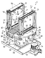
- FIG. 1 shows a perspective view of the device according to the invention
- FIG. 2 shows a magnified perspective illustration of the device according to the invention for forming a stack from printed products
- FIG. 3 shows a plan view onto the device according to FIG. 2 ;
- FIG. 4 shows a perspective illustration of a drive device of a device forming a stacking receptacle provided for pushing out the stack from the stacking receptacle;
- FIG. 5 shows a plan view onto the drive device illustrated in FIG. 4 .
- FIG. 1 illustrates a device 1 for pushing out a stack of printed products 3 stacked on a table 2 at the end of a stacking receptacle 5 , wherein the stack 4 is illustrated in dash-dotted lines.
- the end of the stacking receptacle 5 from where the printed products 3 can be removed in two opposite directions F, F′, is comprised—viewed in the pushing direction F, F′—of two opposite lateral sidewalls 6 , 7 , which must not be mandatorily provided as complete solid walls.
- vertical guide rails 8 , 9 ; 10 , 11 are driveable in the pushing direction F, F′; the guide rails form together with the oppositely positioned guide rails a forward (leading) and rearward receptacle boundary.
- the guide rails 8 , 9 form a forward receptacle boundary and the guide rails 10 , 11 form a rearward receptacle boundary or a pushing device 12 .
- the guide rails 8 , 9 form the rearward receptacle boundary or the pushing device.
- the table 2 forming a support for the stack 4 is a roller table 2 comprised of several conveying rollers 14 , which are positioned sequentially behind one another in the pushing direction F, F′ and are freely rotatably supported in a frame 13 .
- the table 2 is provided with lateral support rails 15 and forms a planar support surface between the sidewalls 6 , 7 .
- the roller table 2 is supported on a rotary frame 16 to be described in the following.
- the guide rails 8 through 11 which match at least the stacking height, circulate about vertical axes that, viewed in the pushing direction, are located at the ends of the sidewalls.
- the upper and the lower end of a guide rail 8 through 11 is attached to an endless toothed belt 17 , 18 or 19 , 20 or a link chain, respectively, which are guided on driven deflection rollers 21 through 28 or 21 ′ through 28 ′.
- deflection rollers 21 through 28 or 21 ′ through 28 ′ are positioned on the opposite sidewalls 7 , 6 correlated with the toothed belt 17 through 20 for the guide rails 8 through 11 forming the leading receptacle boundary or the rearward receptacle boundary. This is illustrated in FIG. 2 .
- the lowermost and the uppermost deflection rollers 21 , 22 and 25 , 26 or 21 ′, 22 ′ and 25 , 26 ′ are provided for the guide rails 8 , 9 forming the leading receptacle boundary, while the deflection rollers 23 , 24 , 27 , 28 or 23 ′, 24 ′, 27 ′, 28 ′ directly neighboring the deflection rollers 21 , 22 , 25 , 26 or 21 ′ 22 ′ 25 ′ 26 ′ are correlated with the rearward receptacle boundary or the pushing device 12 .
- the guide rails 8 , 9 or 10 , 11 forming the forward receptacle boundary, respectively, or the rearward receptacle boundary or the toothed belts 17 through 20 or 17 ′ through 20 ′ are connected to a drive device 29 , 30 , respectively.
- the drive devices 29 , 30 have a toothed belt gear 31 , 32 and are driven in a controlled fashion synchronously or separately, i.e., they have drive motors 33 , 34 which have a rotary angle control.
- FIG. 3 shows both drive devices 29 , 30
- FIGS. 4 and 5 show the drive device 30 separately.
- Each sidewall (guide wall) 6 , 7 of the stacking receptacle 5 has arranged at the ends viewed in the pushing direction F, F′ two pulling or traction means 17 through 20 or 17 ′ through 20 ′, respectively, which circulate about vertically extending axes.
- One pair is arranged at the upper end area and at the lower end area of the guide rails 8 through 11 or 8 ′, respectively.
- the pulling means 17 through 20 or 17 ′ through 20 ′ circulate on deflection rollers 21 through 28 or 21 ′ through 28 ′.
- the guide rails 8 , 9 , 10 , 11 forming the forward and rearward receptacle boundaries, when viewed in the pushing direction F, F′, are connected drivingly to both drive devices 29 , 30 and can be used synchronously for the pushing process and independently for the adjustment of the receptacle to the product size in the pushing direction F, F′.
- the deflection rollers 22 , 22 ′ and 26 , 26 ′ are fixedly connected to the drive shafts 37 ′, 38 ′, while the deflection rollers 25 , 25 ′ that are drivingly connected by the pulling means 17 , 19 , 17 ′, 19 ′ to the deflection rollers 22 , 22 ′ and 26 , 26 ′ are arranged freely rotatable on the shafts 37 , 38 .
- the drive shafts 37 , 38 are fixedly connected to the deflection rollers 23 , 27 and 23 ′, 27 ′ while the deflection rollers 24 , 28 and 24 ′, 28 ′, drivingly connected to the pulling means 18 , 20 and 18 ′, 20 ′, are arranged freely rotatable on the drive shafts 37 , 38 ′.
- deflection rollers 24 , 28 and 24 ′, 28 ′ can be connected with the drive shafts 37 ′, 38 ′.
- the toothed belt gears 31 , 32 of the drive devices 29 , 30 are arranged on the underside of the rotary frame 16 by means of bearing supports 35 , 36 and about two drive shafts 37 , 38 , 37 ′, 38 ′ of the guide rails 8 through 11 or 8 ′ through 11 ′ positioned opposite one another in a direction transverse to the pushing direction F, F′; two deflection rollers 39 , 40 , 39 ′, 40 ′ are drivingly connected thereto, respectively.
- On the bearing supports 35 , 36 , 35 ′, 36 ′ freely rotating support rollers 43 , 44 are supported which support a toothed belt 41 , 42 .
- the drive motors 33 , 34 of the toothed belt gears 31 , 32 are suspended by means of an intermediate gear 45 , 46 from a support 47 (not visible, 48 ) that is connected to the rotary frame 16 .
- the supports 47 , 48 are connected to a support frame 49 which has a support 50 , 51 correlated with the sidewall 6 , 7 , respectively.
- the drive shafts 36 , 36 ′, 37 , 37 ′ of the guide rails 8 through 11 are supported. They are movably supported on guide rods (not illustrated) of a guide arrangement that are arranged in a direction transverse to the pushing direction F, F′ and are anchored in the rotary frame 16 .
- FIG. 2 shows bores 53 , 53 ′, 54 , 54 ′ which are penetrated by the guide rods fastened on the rotary frame 16 for movement of the supports 50 , 51 .
- the supports 50 , 51 of the support frame 49 for changing the spacing between the sidewalls 6 , 7 , are driven by a spindle drive 55 for approaching one another and moving away from one another.
- a telescopically driven guide device 56 , 57 is provided which is comprised of two guide parts 58 , 59 or 58 ′ 59 ′ that are relatively movable on one another.
- One ( 58 , 58 ′) forms a guide groove for receiving the other.
- the guide parts 58 , 59 and 58 ′, 59 ′ are connected to the support frame 49 , and the guide part 58 , 58 ′ are suitable for attachment of the supports 47 , 48 on which the drive motor 33 , 34 of a drive device 29 , 30 is suspended so that the toothed belts 41 , 42 remain tensioned by compensation upon adjustment of the guide walls 6 , 7 .
- the spindle drive 55 is provided (see FIGS. 1 through 3 ). It is comprised of a gear motor 60 fastened on the rotary frame 16 ; a shaft 61 supported on the rotary frame 16 in a position extending transversely to the pushing direction F, F′ is in driving connection with the gear motor 60 ( FIG. 3 ). On this shaft 61 , a pulley 62 , 63 for a lateral adjustment of the guide walls 6 , 7 and of the stacking receptacle 5 is provided, respectively.
- the pulleys are drivingly connected by means of toothed drive belts or a chain 64 , 65 with a spindle rod 66 , 67 provided for moving the guide walls 6 , 7 , wherein the spindle rods 66 , 67 have oppositely acting threads, i.e., a left-handed thread and a right-handed thread. Because of the oppositely oriented movements of the guide walls 6 , 7 or of the supports 50 , 51 of the support frame 49 , the toothed belt 41 , 42 guided through a compensation loop remains tensioned.
- FIG. 1 also shows a device 1 , which is embodied as a compensating stacker, having at its underside a drum 72 that is fixedly connected to the rotary frame 16 and is supported on a machine frame 73 and in driving connection with a stationary electric motor 74 .
- the stacked partial stacks which are stacked alternatingly in an arrangement rotated by 180 degrees, can be pressed before being moved out by lifting the roller table 2 against counter elements 75 that can be moved by the guide walls 6 , 7 into the stacking receptacle 5 .
- the roller table 2 can be lifted and lowered.
- support members 76 are fastened at the top and at the bottom; the support members 76 are positioned, when the stack 4 is pushed out of the stacking receptacle 5 , on the side of the guide walls 6 , 7 facing the stack 4 .
- the drive shafts 37 , 38 and 37 ′, 38 ′ correlated with one of the guide walls 6 , 7 , respectively, are supported at their upper end in a plate 77 connecting the drive shafts.
Applications Claiming Priority (2)
| Application Number | Priority Date | Filing Date | Title |
|---|---|---|---|
| EP02405400.9-1256 | 2002-05-17 | ||
| EP02405400A EP1362817B1 (de) | 2002-05-17 | 2002-05-17 | Einrichtung zum Ausstossen von auf einem Tisch gestapelten Druckerzeugnissen. |
Publications (2)
| Publication Number | Publication Date |
|---|---|
| US20030215322A1 US20030215322A1 (en) | 2003-11-20 |
| US6966743B2 true US6966743B2 (en) | 2005-11-22 |
Family
ID=8185815
Family Applications (1)
| Application Number | Title | Priority Date | Filing Date |
|---|---|---|---|
| US10/440,558 Expired - Fee Related US6966743B2 (en) | 2002-05-17 | 2003-05-15 | Device for pushing a stack of printed products from a table |
Country Status (7)
| Country | Link |
|---|---|
| US (1) | US6966743B2 (de) |
| EP (1) | EP1362817B1 (de) |
| AT (1) | ATE390377T1 (de) |
| DE (1) | DE50211961D1 (de) |
| DK (1) | DK1362817T3 (de) |
| ES (1) | ES2303543T3 (de) |
| NO (1) | NO20032224L (de) |
Cited By (4)
| Publication number | Priority date | Publication date | Assignee | Title |
|---|---|---|---|---|
| US20040140607A1 (en) * | 2003-01-14 | 2004-07-22 | Ferag Ag | Apparatus for forming stacks of flat objects |
| US20130149096A1 (en) * | 2011-12-07 | 2013-06-13 | Ferag Ag | Device and method for composing two-dimensional products, in particular printed products |
| US20130209214A1 (en) * | 2012-02-10 | 2013-08-15 | Illinois Tool Works Inc. | Pusher assembly with dynamic width adjustment for stacker |
| US20130341158A1 (en) * | 2012-06-26 | 2013-12-26 | Shenzhen China Star Optoelectronics Technology Co. Ltd. | Turntable Device for Substrate and Substrate Transporting System |
Families Citing this family (3)
| Publication number | Priority date | Publication date | Assignee | Title |
|---|---|---|---|---|
| US20060280542A1 (en) * | 2005-05-25 | 2006-12-14 | Thieme Gmbh & Co. Kg | Flatbed printing machine |
| EP2133301B1 (de) * | 2008-05-23 | 2011-06-29 | Ferag AG | Drehhubtisch |
| EP2192067B1 (de) * | 2008-11-28 | 2013-09-18 | Müller Martini Holding AG | Stapelvorrichtung für Druckprodukte |
Citations (13)
| Publication number | Priority date | Publication date | Assignee | Title |
|---|---|---|---|---|
| US3532230A (en) | 1968-04-12 | 1970-10-06 | Cutler Hammer Inc | High speed counter stacker for flexible articles |
| US3595370A (en) * | 1969-07-03 | 1971-07-27 | Yuji Fujishiro | Apparatus for stacking and transferring bundles of printed sheets in super-high-speed rolling press |
| US3599807A (en) * | 1970-02-02 | 1971-08-17 | Cutler Hammer Inc | Article counter-stacker having mechanically operated gates on the stack-receiving table |
| CH567996A5 (en) | 1973-06-22 | 1975-10-15 | Ferag Ag | Equipment for stacking printed products - has stacking shaft with pushing out devices along two sides |
| US4055245A (en) * | 1975-04-16 | 1977-10-25 | Wamac Ab | Device with collecting basket for collecting printed matter in a pile and discharging the same |
| US4068567A (en) | 1977-01-31 | 1978-01-17 | Cutler-Hammer, Inc. | Combined ejector-gate means for rotatable table of an article counter-stacker |
| US4103785A (en) * | 1976-08-18 | 1978-08-01 | Wiseman Raymond L | Apparatus for rotating and discharging articles |
| EP0153983A1 (de) | 1984-01-20 | 1985-09-11 | Rima Enterprises, Inc. | Vorrichtung zum Stapeln von Signaturen |
| US4725180A (en) * | 1986-02-17 | 1988-02-16 | Shin Osaka Zoki Co., Ltd. | Apparatus for handling signatures before binding |
| US4749077A (en) * | 1985-03-01 | 1988-06-07 | Quipp, Incorporated | Pusher assembly for a turntable employing plural stepper motors |
| US5433582A (en) * | 1994-06-14 | 1995-07-18 | Medina; Pete R. | Device for discharging papers |
| FR2806396A1 (fr) | 2000-03-15 | 2001-09-21 | Sarl Serop Concept | Machine pour l'empilage ou le desempilage automatique d'objets plats |
| US6692220B2 (en) * | 2001-07-05 | 2004-02-17 | Müller Martini Holding AG | Device for transporting printed products placed in a stack on a support |
-
2002
- 2002-05-17 DE DE50211961T patent/DE50211961D1/de not_active Expired - Lifetime
- 2002-05-17 EP EP02405400A patent/EP1362817B1/de not_active Expired - Lifetime
- 2002-05-17 AT AT02405400T patent/ATE390377T1/de active
- 2002-05-17 DK DK02405400T patent/DK1362817T3/da active
- 2002-05-17 ES ES02405400T patent/ES2303543T3/es not_active Expired - Lifetime
-
2003
- 2003-05-15 US US10/440,558 patent/US6966743B2/en not_active Expired - Fee Related
- 2003-05-16 NO NO20032224A patent/NO20032224L/no not_active Application Discontinuation
Patent Citations (13)
| Publication number | Priority date | Publication date | Assignee | Title |
|---|---|---|---|---|
| US3532230A (en) | 1968-04-12 | 1970-10-06 | Cutler Hammer Inc | High speed counter stacker for flexible articles |
| US3595370A (en) * | 1969-07-03 | 1971-07-27 | Yuji Fujishiro | Apparatus for stacking and transferring bundles of printed sheets in super-high-speed rolling press |
| US3599807A (en) * | 1970-02-02 | 1971-08-17 | Cutler Hammer Inc | Article counter-stacker having mechanically operated gates on the stack-receiving table |
| CH567996A5 (en) | 1973-06-22 | 1975-10-15 | Ferag Ag | Equipment for stacking printed products - has stacking shaft with pushing out devices along two sides |
| US4055245A (en) * | 1975-04-16 | 1977-10-25 | Wamac Ab | Device with collecting basket for collecting printed matter in a pile and discharging the same |
| US4103785A (en) * | 1976-08-18 | 1978-08-01 | Wiseman Raymond L | Apparatus for rotating and discharging articles |
| US4068567A (en) | 1977-01-31 | 1978-01-17 | Cutler-Hammer, Inc. | Combined ejector-gate means for rotatable table of an article counter-stacker |
| EP0153983A1 (de) | 1984-01-20 | 1985-09-11 | Rima Enterprises, Inc. | Vorrichtung zum Stapeln von Signaturen |
| US4749077A (en) * | 1985-03-01 | 1988-06-07 | Quipp, Incorporated | Pusher assembly for a turntable employing plural stepper motors |
| US4725180A (en) * | 1986-02-17 | 1988-02-16 | Shin Osaka Zoki Co., Ltd. | Apparatus for handling signatures before binding |
| US5433582A (en) * | 1994-06-14 | 1995-07-18 | Medina; Pete R. | Device for discharging papers |
| FR2806396A1 (fr) | 2000-03-15 | 2001-09-21 | Sarl Serop Concept | Machine pour l'empilage ou le desempilage automatique d'objets plats |
| US6692220B2 (en) * | 2001-07-05 | 2004-02-17 | Müller Martini Holding AG | Device for transporting printed products placed in a stack on a support |
Cited By (8)
| Publication number | Priority date | Publication date | Assignee | Title |
|---|---|---|---|---|
| US20040140607A1 (en) * | 2003-01-14 | 2004-07-22 | Ferag Ag | Apparatus for forming stacks of flat objects |
| US7828507B2 (en) * | 2003-01-14 | 2010-11-09 | Ferag Ag | Stack turning apparatus with multiple drive means to straighten and eject stack from turntable |
| US20130149096A1 (en) * | 2011-12-07 | 2013-06-13 | Ferag Ag | Device and method for composing two-dimensional products, in particular printed products |
| US9221628B2 (en) * | 2011-12-07 | 2015-12-29 | Ferg Ag | Device and method for composing two-dimensional products, in particular printed products |
| US20130209214A1 (en) * | 2012-02-10 | 2013-08-15 | Illinois Tool Works Inc. | Pusher assembly with dynamic width adjustment for stacker |
| US9181061B2 (en) * | 2012-02-10 | 2015-11-10 | Signode Industrial Group Llc | Pusher assembly with dynamic width adjustment for stacker |
| US20130341158A1 (en) * | 2012-06-26 | 2013-12-26 | Shenzhen China Star Optoelectronics Technology Co. Ltd. | Turntable Device for Substrate and Substrate Transporting System |
| US8776983B2 (en) * | 2012-06-26 | 2014-07-15 | Shenzhen China Star Optoelectronics Technology Co., Ltd | Turntable device for substrate and substrate transporting system |
Also Published As
| Publication number | Publication date |
|---|---|
| DK1362817T3 (da) | 2008-07-28 |
| ATE390377T1 (de) | 2008-04-15 |
| EP1362817B1 (de) | 2008-03-26 |
| EP1362817A1 (de) | 2003-11-19 |
| DE50211961D1 (de) | 2008-05-08 |
| NO20032224D0 (no) | 2003-05-16 |
| US20030215322A1 (en) | 2003-11-20 |
| ES2303543T3 (es) | 2008-08-16 |
| NO20032224L (no) | 2003-11-18 |
Similar Documents
| Publication | Publication Date | Title |
|---|---|---|
| US4927321A (en) | Device for stacking batches of flat objects in a vertical file | |
| US4764074A (en) | Pallet loading apparatus | |
| US20060285947A1 (en) | Method and device for manipulating load containers | |
| US6966743B2 (en) | Device for pushing a stack of printed products from a table | |
| CN113401628B (zh) | 盒型货物的整流码垛一体输送装置及其整流码垛方法 | |
| CN109095254A (zh) | 一种不间断式高效堆码机 | |
| CN109399313A (zh) | 纸箱堆放设备 | |
| CN109178447B (zh) | 一种新型袋装纸尿裤高速堆叠侧推系统 | |
| CA2454925C (en) | Apparatus for forming stacks of flat objects | |
| CN213378637U (zh) | 一种三辊卷板机的自动送料装置 | |
| KR20070015742A (ko) | 컨베이어 장치 | |
| CN113697367A (zh) | 一种基于物联网的全自动分拣智能物流设备 | |
| CN217260807U (zh) | 一种纸杯装箱装置 | |
| EP1084968A1 (de) | Vorrichtung zum Sortieren von Produkten | |
| CN217971470U (zh) | 一种砖坯码垛机 | |
| CA2272283C (en) | Collector apparatus and method | |
| CN115818199A (zh) | 一种板材分流输送装置 | |
| CN212268840U (zh) | 一种瓦楞纸箱生产用堆码机 | |
| CA1318276C (en) | Device suitable for feeding a laminated stack into a heated press and for removing the laminated stack from the press | |
| CN210884413U (zh) | 皮带输送机及分路传输装置 | |
| CN210455367U (zh) | 一种便于调节滑斗速度的爬坡输送装置 | |
| CN113635598B (zh) | 一种瓦楞纸箱切割机的进料系统 | |
| CN112758744A (zh) | 一种自动转向装置 | |
| CN219044748U (zh) | 一种用于布料处理装置的落布装置 | |
| CN219929183U (zh) | 一种纸箱加工用纸箱片自动堆码装置 |
Legal Events
| Date | Code | Title | Description |
|---|---|---|---|
| AS | Assignment |
Owner name: MULLER MARTINI HOLDING AG, SWITZERLAND Free format text: ASSIGNMENT OF ASSIGNORS INTEREST;ASSIGNOR:EUGSTER, ALBERT;REEL/FRAME:014095/0208 Effective date: 20030514 |
|
| FPAY | Fee payment |
Year of fee payment: 4 |
|
| FPAY | Fee payment |
Year of fee payment: 8 |
|
| REMI | Maintenance fee reminder mailed | ||
| LAPS | Lapse for failure to pay maintenance fees |
Free format text: PATENT EXPIRED FOR FAILURE TO PAY MAINTENANCE FEES (ORIGINAL EVENT CODE: EXP.) |
|
| STCH | Information on status: patent discontinuation |
Free format text: PATENT EXPIRED DUE TO NONPAYMENT OF MAINTENANCE FEES UNDER 37 CFR 1.362 |
|
| FP | Lapsed due to failure to pay maintenance fee |
Effective date: 20171122 |