EP1340877A2 - Türantrieb - Google Patents
Türantrieb Download PDFInfo
- Publication number
- EP1340877A2 EP1340877A2 EP03004486A EP03004486A EP1340877A2 EP 1340877 A2 EP1340877 A2 EP 1340877A2 EP 03004486 A EP03004486 A EP 03004486A EP 03004486 A EP03004486 A EP 03004486A EP 1340877 A2 EP1340877 A2 EP 1340877A2
- Authority
- EP
- European Patent Office
- Prior art keywords
- drive device
- wing
- designed
- movement
- sensor
- Prior art date
- Legal status (The legal status is an assumption and is not a legal conclusion. Google has not performed a legal analysis and makes no representation as to the accuracy of the status listed.)
- Granted
Links
Images
Classifications
-
- E—FIXED CONSTRUCTIONS
- E05—LOCKS; KEYS; WINDOW OR DOOR FITTINGS; SAFES
- E05F—DEVICES FOR MOVING WINGS INTO OPEN OR CLOSED POSITION; CHECKS FOR WINGS; WING FITTINGS NOT OTHERWISE PROVIDED FOR, CONCERNED WITH THE FUNCTIONING OF THE WING
- E05F3/00—Closers or openers with braking devices, e.g. checks; Construction of pneumatic or liquid braking devices
- E05F3/22—Additional arrangements for closers, e.g. for holding the wing in opened or other position
- E05F3/223—Hydraulic power-locks, e.g. with electrically operated hydraulic valves
-
- E—FIXED CONSTRUCTIONS
- E05—LOCKS; KEYS; WINDOW OR DOOR FITTINGS; SAFES
- E05F—DEVICES FOR MOVING WINGS INTO OPEN OR CLOSED POSITION; CHECKS FOR WINGS; WING FITTINGS NOT OTHERWISE PROVIDED FOR, CONCERNED WITH THE FUNCTIONING OF THE WING
- E05F15/00—Power-operated mechanisms for wings
- E05F15/40—Safety devices, e.g. detection of obstructions or end positions
- E05F15/42—Detection using safety edges
-
- E—FIXED CONSTRUCTIONS
- E05—LOCKS; KEYS; WINDOW OR DOOR FITTINGS; SAFES
- E05F—DEVICES FOR MOVING WINGS INTO OPEN OR CLOSED POSITION; CHECKS FOR WINGS; WING FITTINGS NOT OTHERWISE PROVIDED FOR, CONCERNED WITH THE FUNCTIONING OF THE WING
- E05F3/00—Closers or openers with braking devices, e.g. checks; Construction of pneumatic or liquid braking devices
- E05F3/04—Closers or openers with braking devices, e.g. checks; Construction of pneumatic or liquid braking devices with liquid piston brakes
- E05F3/10—Closers or openers with braking devices, e.g. checks; Construction of pneumatic or liquid braking devices with liquid piston brakes with a spring, other than a torsion spring, and a piston, the axes of which are the same or lie in the same direction
- E05F3/102—Closers or openers with braking devices, e.g. checks; Construction of pneumatic or liquid braking devices with liquid piston brakes with a spring, other than a torsion spring, and a piston, the axes of which are the same or lie in the same direction with rack-and-pinion transmission between driving shaft and piston within the closer housing
-
- E—FIXED CONSTRUCTIONS
- E05—LOCKS; KEYS; WINDOW OR DOOR FITTINGS; SAFES
- E05F—DEVICES FOR MOVING WINGS INTO OPEN OR CLOSED POSITION; CHECKS FOR WINGS; WING FITTINGS NOT OTHERWISE PROVIDED FOR, CONCERNED WITH THE FUNCTIONING OF THE WING
- E05F3/00—Closers or openers with braking devices, e.g. checks; Construction of pneumatic or liquid braking devices
- E05F3/04—Closers or openers with braking devices, e.g. checks; Construction of pneumatic or liquid braking devices with liquid piston brakes
- E05F3/12—Special devices controlling the circulation of the liquid, e.g. valve arrangement
-
- E—FIXED CONSTRUCTIONS
- E05—LOCKS; KEYS; WINDOW OR DOOR FITTINGS; SAFES
- E05F—DEVICES FOR MOVING WINGS INTO OPEN OR CLOSED POSITION; CHECKS FOR WINGS; WING FITTINGS NOT OTHERWISE PROVIDED FOR, CONCERNED WITH THE FUNCTIONING OF THE WING
- E05F15/00—Power-operated mechanisms for wings
- E05F15/40—Safety devices, e.g. detection of obstructions or end positions
- E05F15/41—Detection by monitoring transmitted force or torque; Safety couplings with activation dependent upon torque or force, e.g. slip couplings
-
- E—FIXED CONSTRUCTIONS
- E05—LOCKS; KEYS; WINDOW OR DOOR FITTINGS; SAFES
- E05F—DEVICES FOR MOVING WINGS INTO OPEN OR CLOSED POSITION; CHECKS FOR WINGS; WING FITTINGS NOT OTHERWISE PROVIDED FOR, CONCERNED WITH THE FUNCTIONING OF THE WING
- E05F15/00—Power-operated mechanisms for wings
- E05F15/70—Power-operated mechanisms for wings with automatic actuation
- E05F15/71—Power-operated mechanisms for wings with automatic actuation responsive to temperature changes, rain, wind or noise
-
- E—FIXED CONSTRUCTIONS
- E05—LOCKS; KEYS; WINDOW OR DOOR FITTINGS; SAFES
- E05F—DEVICES FOR MOVING WINGS INTO OPEN OR CLOSED POSITION; CHECKS FOR WINGS; WING FITTINGS NOT OTHERWISE PROVIDED FOR, CONCERNED WITH THE FUNCTIONING OF THE WING
- E05F15/00—Power-operated mechanisms for wings
- E05F15/40—Safety devices, e.g. detection of obstructions or end positions
- E05F15/42—Detection using safety edges
- E05F2015/483—Detection using safety edges for detection during opening
-
- E—FIXED CONSTRUCTIONS
- E05—LOCKS; KEYS; WINDOW OR DOOR FITTINGS; SAFES
- E05F—DEVICES FOR MOVING WINGS INTO OPEN OR CLOSED POSITION; CHECKS FOR WINGS; WING FITTINGS NOT OTHERWISE PROVIDED FOR, CONCERNED WITH THE FUNCTIONING OF THE WING
- E05F5/00—Braking devices, e.g. checks; Stops; Buffers
- E05F5/12—Braking devices, e.g. checks; Stops; Buffers specially for preventing the closing of a wing before another wing has been closed
-
- E—FIXED CONSTRUCTIONS
- E05—LOCKS; KEYS; WINDOW OR DOOR FITTINGS; SAFES
- E05Y—INDEXING SCHEME RELATING TO HINGES OR OTHER SUSPENSION DEVICES FOR DOORS, WINDOWS OR WINGS AND DEVICES FOR MOVING WINGS INTO OPEN OR CLOSED POSITION, CHECKS FOR WINGS AND WING FITTINGS NOT OTHERWISE PROVIDED FOR, CONCERNED WITH THE FUNCTIONING OF THE WING
- E05Y2400/00—Electronic control; Power supply; Power or signal transmission; User interfaces
- E05Y2400/10—Electronic control
- E05Y2400/20—Electronic control of brakes, disengaging means, holders or stops
-
- E—FIXED CONSTRUCTIONS
- E05—LOCKS; KEYS; WINDOW OR DOOR FITTINGS; SAFES
- E05Y—INDEXING SCHEME RELATING TO HINGES OR OTHER SUSPENSION DEVICES FOR DOORS, WINDOWS OR WINGS AND DEVICES FOR MOVING WINGS INTO OPEN OR CLOSED POSITION, CHECKS FOR WINGS AND WING FITTINGS NOT OTHERWISE PROVIDED FOR, CONCERNED WITH THE FUNCTIONING OF THE WING
- E05Y2400/00—Electronic control; Power supply; Power or signal transmission; User interfaces
- E05Y2400/10—Electronic control
- E05Y2400/30—Electronic control of motors
- E05Y2400/302—Electronic control of motors during electromotoric braking
-
- E—FIXED CONSTRUCTIONS
- E05—LOCKS; KEYS; WINDOW OR DOOR FITTINGS; SAFES
- E05Y—INDEXING SCHEME RELATING TO HINGES OR OTHER SUSPENSION DEVICES FOR DOORS, WINDOWS OR WINGS AND DEVICES FOR MOVING WINGS INTO OPEN OR CLOSED POSITION, CHECKS FOR WINGS AND WING FITTINGS NOT OTHERWISE PROVIDED FOR, CONCERNED WITH THE FUNCTIONING OF THE WING
- E05Y2400/00—Electronic control; Power supply; Power or signal transmission; User interfaces
- E05Y2400/10—Electronic control
- E05Y2400/30—Electronic control of motors
- E05Y2400/32—Position control, detection or monitoring
- E05Y2400/334—Position control, detection or monitoring by using pulse generators
- E05Y2400/336—Position control, detection or monitoring by using pulse generators of the angular type
-
- E—FIXED CONSTRUCTIONS
- E05—LOCKS; KEYS; WINDOW OR DOOR FITTINGS; SAFES
- E05Y—INDEXING SCHEME RELATING TO HINGES OR OTHER SUSPENSION DEVICES FOR DOORS, WINDOWS OR WINGS AND DEVICES FOR MOVING WINGS INTO OPEN OR CLOSED POSITION, CHECKS FOR WINGS AND WING FITTINGS NOT OTHERWISE PROVIDED FOR, CONCERNED WITH THE FUNCTIONING OF THE WING
- E05Y2400/00—Electronic control; Power supply; Power or signal transmission; User interfaces
- E05Y2400/10—Electronic control
- E05Y2400/30—Electronic control of motors
- E05Y2400/40—Control units therefore
-
- E—FIXED CONSTRUCTIONS
- E05—LOCKS; KEYS; WINDOW OR DOOR FITTINGS; SAFES
- E05Y—INDEXING SCHEME RELATING TO HINGES OR OTHER SUSPENSION DEVICES FOR DOORS, WINDOWS OR WINGS AND DEVICES FOR MOVING WINGS INTO OPEN OR CLOSED POSITION, CHECKS FOR WINGS AND WING FITTINGS NOT OTHERWISE PROVIDED FOR, CONCERNED WITH THE FUNCTIONING OF THE WING
- E05Y2400/00—Electronic control; Power supply; Power or signal transmission; User interfaces
- E05Y2400/10—Electronic control
- E05Y2400/52—Safety arrangements
- E05Y2400/53—Wing impact prevention or reduction
- E05Y2400/532—Emergency braking
-
- E—FIXED CONSTRUCTIONS
- E05—LOCKS; KEYS; WINDOW OR DOOR FITTINGS; SAFES
- E05Y—INDEXING SCHEME RELATING TO HINGES OR OTHER SUSPENSION DEVICES FOR DOORS, WINDOWS OR WINGS AND DEVICES FOR MOVING WINGS INTO OPEN OR CLOSED POSITION, CHECKS FOR WINGS AND WING FITTINGS NOT OTHERWISE PROVIDED FOR, CONCERNED WITH THE FUNCTIONING OF THE WING
- E05Y2400/00—Electronic control; Power supply; Power or signal transmission; User interfaces
- E05Y2400/60—Power supply; Power or signal transmission
- E05Y2400/61—Power supply
- E05Y2400/616—Generators
-
- E—FIXED CONSTRUCTIONS
- E05—LOCKS; KEYS; WINDOW OR DOOR FITTINGS; SAFES
- E05Y—INDEXING SCHEME RELATING TO HINGES OR OTHER SUSPENSION DEVICES FOR DOORS, WINDOWS OR WINGS AND DEVICES FOR MOVING WINGS INTO OPEN OR CLOSED POSITION, CHECKS FOR WINGS AND WING FITTINGS NOT OTHERWISE PROVIDED FOR, CONCERNED WITH THE FUNCTIONING OF THE WING
- E05Y2600/00—Mounting or coupling arrangements for elements provided for in this subclass
- E05Y2600/40—Mounting location; Visibility of the elements
- E05Y2600/458—Mounting location; Visibility of the elements in or on a transmission member
-
- E—FIXED CONSTRUCTIONS
- E05—LOCKS; KEYS; WINDOW OR DOOR FITTINGS; SAFES
- E05Y—INDEXING SCHEME RELATING TO HINGES OR OTHER SUSPENSION DEVICES FOR DOORS, WINDOWS OR WINGS AND DEVICES FOR MOVING WINGS INTO OPEN OR CLOSED POSITION, CHECKS FOR WINGS AND WING FITTINGS NOT OTHERWISE PROVIDED FOR, CONCERNED WITH THE FUNCTIONING OF THE WING
- E05Y2800/00—Details, accessories and auxiliary operations not otherwise provided for
- E05Y2800/20—Combinations of elements
- E05Y2800/21—Combinations of elements of identical elements, e.g. of identical compression springs
-
- E—FIXED CONSTRUCTIONS
- E05—LOCKS; KEYS; WINDOW OR DOOR FITTINGS; SAFES
- E05Y—INDEXING SCHEME RELATING TO HINGES OR OTHER SUSPENSION DEVICES FOR DOORS, WINDOWS OR WINGS AND DEVICES FOR MOVING WINGS INTO OPEN OR CLOSED POSITION, CHECKS FOR WINGS AND WING FITTINGS NOT OTHERWISE PROVIDED FOR, CONCERNED WITH THE FUNCTIONING OF THE WING
- E05Y2900/00—Application of doors, windows, wings or fittings thereof
- E05Y2900/10—Application of doors, windows, wings or fittings thereof for buildings or parts thereof
- E05Y2900/13—Application of doors, windows, wings or fittings thereof for buildings or parts thereof characterised by the type of wing
- E05Y2900/132—Doors
Definitions
- the invention relates to a drive device according to the preamble of the claim 1.
- DE 91 02 344 U1 shows a trained as a door closer drive device for automatically closing a rotatably mounted, designed as a door leaf Wing.
- An energy storage acts on a displaceable in the door closer housing guided piston in the closing direction, so that the wing under the effect of Energy storage is closable.
- the closing process is by means of a hydraulic Damping device formed influencing device damped.
- the damping device has various subfunctions, for example a closing dampening and a so-called final stroke shortly before reaching the Closed position;
- Each of these sub-functions requires the need for a separate one Housing channels and a separate control valve. This is elaborate in the Manufacture and in the setting on the mounted drive device.
- US 4,148,111 is designed as a door closer drive for automatic Close a rotatably mounted door known.
- This one has Housing on, in which a trained as a closer shaft output member is rotatably mounted.
- the closer shaft acts as a pinion and rack trained transmission with a linearly displaceably guided in the housing Pistons together, with a e.g. designed as a closing spring mechanical Energy storage applied to the piston in the closing direction.
- An influencing device as a hydraulic, one in an overflow between two of the piston limited housing chambers arranged valve having Damping device is formed, is for damping the closing operation intended.
- the damping device is designed so that the damping the movement of the sash in the closing direction automatically to changes in the Ambient temperature is adjusted by the valve a the flow cross section having plastic element defining, which changes the ambient temperature changes its volume.
- the plastic element expands at temperature increase, so that the flow cross-section reduced accordingly. This ensures that regardless of Changes in the ambient temperature and the resulting changes in viscosity the damping medium a constant flow of the damping medium is ensured by the valve and the damping of the closing movement thus independent of temperature.
- a disadvantage of the drive device shown is that while an adaptation ensured to the described changes in viscosity of the damping medium is an automatic adaptation to other special, through the changes
- other operating conditions triggered ambient conditions not is provided. For example, it may be due to draft within a building or by wind come to that the wing is not completely closed is, especially if when reaching the closed position, the resistance a latch is overcome.
- the closing loss is due to manual adjustment of the valve adjustable; however, this attitude always arises a compromise, because at low closing loss, which is a safe Closing the wing even while draft ensures that the wing, if the Draft just does not exist, violently and loudly fall into its closed position.
- the invention has for its object to provide a drive device, which is flexible for different types and sizes of wings, easy to install is a comfortable and independent of the environmental conditions Actuating and at the same time ensuring safe closing of the sash. moreover the drive device should be inexpensive to manufacture.
- the influencing device has an electrically controllable influencing element on, whereby the movement of the wing directly or indirectly by a Sensor is detected, the output signal to an input of a control device is supplied, which controls the influencing Elemeht.
- the Control device is designed so that the influencing element dependent from the movement of the wing in its influence on the energy output of the energy storage is changeable. This will be a to the actual wing movement in the sense of a regulation adapted movement sequence of the door drive allows.
- the movement of the wing detecting sensor is in preferred embodiments the drive device as a rotary encoder, for example as an incremental encoder or designed as absolute value encoder.
- the encoder can be on the output element be arranged of the door drive.
- the movement of other, with the output member geared connected Components e.g. a linearly displaceable in the drive housing piston, be recorded.
- This can be done, for example, by means of Hall sensors or reed switches respectively.
- the drive device may instead of the or in addition to detecting the output member movement detection of the Pivoting movement of the sash:
- the sensor can then in the range of Rotary axis of the door arranged and designed as a rotary encoder.
- the sensor can also be the linear Detect movement of the slider in the slide, for which Hall sensors or Reed switches are suitable.
- the control device can be a computer device, a memory device and have an electrical energy storage.
- the electrical energy storage can be designed as a replaceable battery. In preferred Designs, the electrical energy storage is designed as a battery.
- the electrical energy store can be used as a capacitive energy store, i. when Capacitor, for example, designed as a so-called gold-cap capacitor be. Another way to provide electrical power to the drive device consists in the use of a fuel cell.
- the Door drive is connected to a power supply network.
- the output signal of the example designed as a multi-pole encoder Sensor is directed to an input of the controller.
- nonvolatile memory device of the control device are Parameter for the possible operating states of the drive device deposited.
- the computer device of the control device are stored Parameter compared with the output signals of the sensor. From these signals are in the computer device directly the opening angle position and the ' Movement speed of the connected to the drive device wing derived.
- the wing allowed a high speed of movement of the wing is that, however, from a certain small opening angle, the movement speed of the wing to a predetermined lower value is slowed down.
- the Shock absorption - especially in the case of doors with a latching latch - is on the way Reaching the closed position again reduced or completely canceled, so that the lock latch can engage reliably.
- the opening movement For example, it may be provided that the wing until reaching a certain opening angle unattenuated, i. alone against the power of the compressed Closing spring is opened that from this particular opening angle but a damping of the opening movement sets in, which is a striking of the Wing against a building part, e.g. against a wall, prevented.
- a movement velocity profile of the wing be deposited wherein each opening angle position of the wing is an optimum moving speed is assigned for the ⁇ ffriungs- and for the closing movement.
- the opening speed depending on the opening speed of the flying ice is adjustable with change of the movement speed profile, i.e.
- Each opening angle of the wing is an adjustable and changeable Value of the opening damping can be assigned.
- the opening loss can be increased and decreased be switched off.
- a hold-open time can be defined so that the wing does not close immediately after the opening process, but only is released after closing the hold open time.
- the hold-open time can be set and changed as well as switched on and off.
- the influencing element can completely fulfill the function of a conventional one Take over locking device and replace it thus. After manual opening of the wing this remains in a predeterminable open position until the Determination is repealed by, for example, the energization of the influencing element is interrupted. It is thus an insert of the drive device on fire doors possible, wherein after evaluation of a smoke sensor signal or in case of power failure, a reliable closure the wing is ensured by the drive device.
- a lifting of the determination of the wing can also by manual Moving the sash to be triggered in the closing direction.
- - with activated Detection a movement of the output member over a predetermined Path detected and as triggering signal for the cancellation of the finding get ranked.
- - with additional housing chamber pressure detection that with activated determination and manual wing operation occurring increase in pressure in one of the housing chambers as triggering the determination.
- Another application of the drive device is - in conjunction with a special freewheel linkage - in a so-called "free swing” function.
- the influencing element locks the closing spring similarly to the above-described locking function in the cocked position.
- the linkage coupling to the output shaft of the drive device allows a relative movement between detected output shaft and the force-transmitting Linkage, allowing the wing to overcome without the force of the closer spring must, is freely movable, as long as the shutter spring is locked.
- a cancellation of the energization of the influencing element a repeal the locking of the closing spring, so that the wing then spring-loaded is closed.
- the influencing element must be designed so that it is fast and accurate can respond to the control signals of the control device.
- An advantageous Design of the influencing element is an electrically controllable Valve, which in an overflow channel, which two in the housing on both sides of Piston connects existing housing chambers, is arranged.
- the electrically controllable valve can, for example, as a bistable solenoid valve be formed, the flow cross section through the clocked switching between the two positions "open” and “closed” can be regulated. Depending on the ratio of the "open” and “closed” pulses to each other, the Flow rate can be adjusted continuously, with a change in the flow rate can be realized very quickly.
- valve cascade instead of a single solenoid valve a valve cascade consisting of several valves connected in parallel be arranged.
- the valves of the valve cascade preferably as bistable solenoid valves are formed, are individually controllable, wherein the flow cross-section the valve cascade is greater, the more valves are opened.
- the gradation The achievable flow cross sections depend on the number of individual valves, i. the more valves in the cascade are arranged parallel to each other are, the finer is the gradation of the flow cross sections.
- valve actuators are suitable with appropriate suitability, for example, piezoelectric actuators or thermal actuators.
- the influencing element as a mechanical Brake device be designed so that optionally on the filling the drive device can be dispensed with a damping medium.
- the mechanical braking device can be mounted on a movable element of the drive device act, for example, directly on the closer shaft or on a rotatably mounted on the closer shaft brake disc or on the Piston.
- the influencing element as an electric Generator be formed.
- the drive device can be dispensed with a damping medium.
- the generator generated during regenerative braking electrical energy, which an electrical resistance is supplied.
- the electrical energy can alternatively or in addition to the electrical energy storage of the control device be supplied.
- the electrical energy store is replaceable or charged via the building's power grid.
- the latter Case may be the supply of electrical energy - if the drive device mounted on the wing - done for example via the force-transmitting linkage.
- the drive device on the wing or fixed solar cells may be arranged, which the electrical energy storage supply with electrical energy.
- the control device of the drive device may also further electrical Have inputs and outputs, e.g. for the connection of the drive device to a central control center. It is thus a central monitoring of the operating state the connected drive devices and optionally Interventions in the operating modes of the drive devices possible.
- a safety sensor device can be arranged in the movement region of the wing be whose output signal is processed in the control device and at a located in the range of motion of the wing obstacle strong damping of the wing movement, possibly leading to a standstill, which avoids impact of the wing against the obstacle. It can be provided that the safety sensor in the housing of the drive device is arranged integrated. This results in the advantage that the evaluation the signals of the safety sensor in the control device of the drive device takes place and thus waives a separate evaluation can be.
- the safety sensor device can in particular the secondary closing edge of the Wing, which forms a crushing and shearing, secure, i. when a Body part or an object with closing wing in the area of Mauschurgikante device, the wing movement is stopped.
- sensors for the environmental conditions for example for Temperature, rain or wind
- the drive device can then be operated adapted to the ambient conditions; e.g. can the Closing movement in cold outside temperatures, rain or strong wind faster than warmer outside temperatures, dryness or calm, to cool the interior closed by the wing, drafts or to prevent the ingress of moisture into the interior.
- the measuring cell of the smoke sensor in the housing of the drive device is arranged integrated;
- the evaluation of the Signals of the measuring cell in the control device of the drive device takes place and thus to a separate transmitter for the measuring cell of the Smoke sensor can be dispensed with.
- operating parameters can already be stored by the manufacturer become. It may additionally be provided that the parameters also at already mounted drive device at any time entered, changeable and storable are.
- an interface may be present on the control device be, wherein the input or change of the operating parameters, for example via a connectable service terminal or via a conventional service terminal PC can be done.
- the PC does not necessarily have to be in close proximity be arranged to the drive device, as well as a data transfer over building-side computer networks or over the Internet is possible.
- the input or Change of the operating parameters also take place from there. It is also conceivable one wireless data transmission for entering or changing the operating parameters, the control device for this purpose a transmitter / receiver device can have.
- the interface may be in an advantageous embodiment of the drive device be designed as a bus interface, which is the connection of the drive device to a building side existing bus system allows. Also the preceding described external sensors may be bus capable and about this Bus interface connected to the control device of the drive device which reduces the cabling effort significantly.
- the drive device may alternatively or in addition to the aforementioned connection options also directly facilities for data display and / or data entry exhibit.
- the memory device to storing operating parameters when commissioning the drive device by a manual movement of the wing according to the desired movement are stored, the signals of the movement of the output member detected sensor in the computer device and evaluated the operating parameters are processed for the movement.
- the memory device may further comprise a time detection device, by means of which the operating conditions of the drive device can be logged. These stored logs may be retrievable for diagnostic purposes.
- the drive device includes a motorized spring force adjustment.
- the closing spring is supported on the one hand on the piston and on the other hand on a displaceably guided in the drive housing spring plate from.
- the spring plate is powered by an electrically actuated actuator, for example by an electric motor whose spindle engages in the spring plate, emotional. Alternatively, this is also the use of an electrochemical actuator conceivable. It is essential that a movement of the spring plate the bias changed the closing spring. In conjunction with the previously described Detecting the movement of the output member of the drive device as well with the actual lst comparison of these measured values with a stored one Movement profile, it is possible to increase the force of the closing spring, if necessary or diminish.
- the closing spring in the closed position of the wing relatively little biased, and when opening the wing then becomes the spring - in addition to the compulsory compression by the movement of the piston - if necessary by the spring plate in addition compressed.
- This additional compression can take place only if the wing is already fully open, so that for the subsequent Closing enough spring force is available, or it can be provided be that the additional compression only when spring-loaded closing of the wing, especially if the closing speed falls below the setpoint stored in the motion profile.
- the operating parameters in the context of a feasible at startup of the drive device "Learning" or by entering door parameters (e.g., dimensions and Weight of the wing).
- door parameters e.g., dimensions and Weight of the wing.
- Another embodiment of the drive device includes a motorized opening assistance.
- an electrically controllable valve is in the overflow arranged a hydraulic pump;
- the pump is powered by an electric motor driven, wherein the electric motor with the control device connected is.
- the electric motor via the control device, which is the manual Opening the wing connected to the drive device by means of a Signal of the sensor has detected, so controlled that the hydraulic medium from the shrinking when opening the wing housing chamber in the is promoted when opening the wing magnifying housing chamber. This creates in the latter housing chamber, an overpressure, the piston in Applied opening direction; for manual opening the wing is thus less Required effort.
- the control of the pump can depend on the opening speed and the opening position of the wing done. This can - as previously described several times - in the memory device the control device be deposited a movement profile. Based on the comparison of the actual wing movement with the stored Movement profile, the electric motor of the pump is driven.
- the pump is reversible, i. in both Flow directions operable pump is formed. Then it is possible that the electric motor of the pump shortly before reaching the open position of the wing - again possibly taking into account the speed of movement of the grand piano - is reversed, i. that the conveying direction of the pump is reversed becomes. This is an opening damping function can be realized.
- the pump acts in the manner of a turbine, i.e. the flowing through. Hydraulic fluid causes the pump to rotate.
- Hydraulic fluid causes the pump to rotate.
- the Electric motor acts as a regenerative brake, the braking effect from the controller based on the comparison of the actual Wing movement is regulated with the stored movement profile.
- a "Final Cut" function is feasible by the braking effect just before reaching the closed position of the wing is withdrawn or canceled.
- the pump can be reversed again, so they then the When closing occurring flow of the hydraulic medium and thus the mechanical Energy storage in the sense of a reliable closure of the wing supported.
- the drive device Due to the fact that the functions of the drive device are learning or programmable and the influencing element a Can take on a variety of functions at the same time, is the drive device extremely flexible. For example, the "end-impact" feature is when needed switchable, without that on the mechanical structure of the drive device changes must be made. On a variety of additional components, such as separate locking devices can be omitted because the influencing element takes over this function.
- the drive housing itself can be dispensed with a variety of hydraulic channels, for example the functions of conventional valves and hydraulic ducts for opening damping, Closing damping and final impact in the influencing element united.
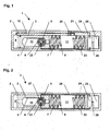
- FIG. 1 shows a drive device 1 designed as a door closer.
- the drive device 1 has a housing 2; this is arranged on a rotatably mounted wing or on a stationary door frame. Alternatively, an integrated in the frame assembly of the housing 2 is conceivable.
- the linearly displaceable in the housing 2 piston 3 is formed as a hollow piston and provided in its interior with a toothing 4, which cooperates with a pinion 6 of a rotatably mounted in the housing 2, designed as a closer shaft output member 5.
- a non-illustrated force-transmitting linkage is arranged rotationally fixed; this can be designed as a sliding arm or as a scissor arm and connects the drive device 1 - depending on the type of mounting - with the stationary door frame or with the wing.
- the piston 3 divides the interior of the housing 2 in two housing chambers 9, 11.
- two closing springs formed as mechanical energy storage 7, 8 are arranged, which with its right in the drawing end on a wall of the housing. 2 and support with its left end on the right end face of the piston 3.
- the mechanical energy storage 7, 8 act on the piston 3 thus to the left; a movement of the piston 3 to the right leads to a compression of the mechanical energy storage 7, 8.
- a damping medium e.g. filled with hydraulic oil.
- the piston 3 moves to the left during the closing movement, it displaces Damping medium from the left housing chamber 9 by the in a longitudinal wall of the housing 2 arranged overflow channel 12 in the right housing chamber 11th
- an electrically controllable valve 20 (schematically ) Shown. This is e.g. designed as a solenoid valve; the valve body Alternatively, it can also be with a rotating electric motor or with piezo actuators or the like can be controlled. An electrical control of the valve 20 - irrespective of its actual implementation - effects a change its flow cross-section. The electrical control of the valve 20 possible modes of the drive device 1 are elsewhere described in detail.
- a sensor 22 is arranged.
- the signals of the sensor 22 are arranged via an electrical line 23 of an arranged in the housing 2 electronic Control device 24 supplied; This receives them to their operation required electrical energy via an electrical line 26 from a also arranged in the housing 2 electrical energy storage 25, as Battery can be formed.
- About another running in the housing 2 electrical Line 21 is an output of the controller 24 to the actuator of Valve 20 connected.
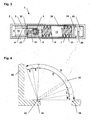
- Figures 2 and 3 show different embodiments of a drive device 1.
- the basic structure of the drive device 1 with housing 2, piston 3 with toothing 4, output member 5 with pinion 6 and mechanical energy storage 7, 8 corresponds to the embodiment shown in Figure 1.
- the arrangement of the sensor 22 of a shaft and the supply of the signals of the sensor 22 via an electrical line 23 to one in the... Described therein also the arrangement of movements of the output member 5 and piston 3 Housing 2 arranged, powered by an energy storage 25 electronic control device 24 correspond to the previous embodiment.
- the drive device 1 instead of the valve arranged in the hydraulic circuit, the drive device 1 according to FIG. 2 has a mechanical braking device 27.
- a mechanical braking device 27 On a filling of the housing 2 with a damping medium can thus possibly even be dispensed with in this embodiment, unless the medium is required for lubrication of the moving parts.
- the electrically controllable braking device 27 is connected via an electrical line 28 to an output of the control device 24 and acts directly on the output member 5 or on a non-rotatably connected thereto brake element, for example on a brake disc.
- the drive device 1 shown in FIG. 3 has a blowing device containing a generator 29.
- the generator 29 is connected by means of a translating gear 31 to the output member 5, so that a slow rotation of the output member 5 causes a rapid rotation of the generator 29.
- the generator 29 is also connected via an electrical line 30 to the controller 24.
- the rotational movement of the output member 5 detected sensor 22 is arranged in this embodiment of the high-speed shaft of the generator 29.
- the braking effect of the generator 29 is achieved in that the control device 24 switches the generator 29 to a variable electrical resistance contained in the control device.
- the electrical energy generated in the regenerative braking can be supplied to the electrical energy storage 25.
- FIG. 4 shows a vane 32 rotatably mounted on a door frame 34 via a hinge 33.
- the total opening angle A of the vane 32 which is equipped with a drive device according to the preceding exemplary embodiments, is limited on the one hand by the closed position of the vane 32 and on the other hand a wall 35.
- a complete opening and closing cycle of the driving device will be described.
- the wing 32 During its complete opening movement, the wing 32 passes through the opening angle partial areas B, C, D, E and F counterclockwise. In the first Opening angle portions B to E, the wing 32 is only against the force the mechanical energy storage without effective damping moves, and at Achieving the last opening angle partial area F becomes the influencing device effectively switched to bounce the wing 32 against the wall 35 or to prevent against the stop buffer. It can be used throughout the opening angle section F be provided for a constant damping, or the Damping can be continuous when passing through the opening angle portion F increase. In particular, the actual opening speed can be through Comparison with a stored target opening speed by continuous Damping control is slowed down to this setpoint.
- the damping of the closing movement is relatively low, so that a rapid Closing movement of the wing 32 in these first opening angle partial areas F until D is reached. If the wing 32 reaches the penultimate opening angle portion C, so sets a higher damping to the wing 32 from the high closing speed decelerate to a lower closing speed.
- the Damping can again be constant in the entire opening angle portion C be or continuously increase - with or without regulation by Soll-lst comparison the closing speed.
- the closing movement may deviate run: Here is in the first four opening angle sections F to C the Damping the closing movement relatively low, allowing a rapid closing movement of the wing 32 reaches in these first opening angle partial areas F to C. becomes. If the wing 32 reaches the last opening angle portion B, so uses a higher damping to the wing 32 of the high closing speed decelerate to a lower closing speed.
- the Damping can again be constant in the entire opening angle portion B be or continuously increase - with or without regulation by Soll-lst comparison the closing speed. Notwithstanding the embodiment With lock latch here sets the deceleration of the high closing speed at a lower closing speed later, so that's, wings 32 so go through a further opening angle range with high closing speed can and thus realized the fastest possible closure of the wing 32 becomes.
- the end stop may, depending on the type of door, on which the drive device is used, switched on or off.
- Another special operating behavior of the drive device can, for example be required if the last opening angle portion in the opening direction F is blocked by a parked item.
- the influencing device now has already in the penultimate opening angle portion E become effective to bounce the wing 32 on the object to prevent.
- the necessary operating parameters like the total opening angle, the opening angle portions - optionally with the individual opening angle partial areas assigned Target movement speeds - and optionally a continuous Movement velocity profile deposited.
- the movement of the grand piano causes a movement corresponding output signal of the controller, which the position of the wing and its direction of movement and speed includes.
- the switched to an input of the control device Sensor signal is in the computer device of the control device compared with the stored operating parameters (setpoint).
- the Influencing device is controlled so that any deviations be compensated between actual and setpoint.
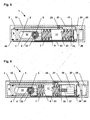
- the drive device 1 shown in FIG. 5 faces the drive device according to the embodiment of Figure 1 additional pressure sensors 40, 42 on.
- a pressure sensor 40 is in the housing chamber 9, in which at Closing of the wing by the displacement of the piston 3 creates an overpressure, arranged.
- the other pressure sensor 42 detects the pressure in the housing chamber 11, in which the mechanical energy storage 7, 8 are arranged; here When opening the sash, an overpressure is created with active opening damping.
- the pressure sensors 40, 42 are by means of electrical lines 41, 43 with the control device 24 connected.
- the pressures detected in the housing chambers 9, 11. This can be applied for one Protection of the drive mechanism against impermissibly high pressures, such as for example, in the case of rapid manual overpressing of the closing ones Door or when too fast opening with effective opening damping done can.
- the closing damping can then be temporarily withdrawn be so that the pressure in the housing chambers 9, 11 a predetermined Limit does not exceed.
- Another application of the pressure sensors 40, 42 is that when activated locking function of the drive device 1 a manual pressing of the wing in the closing direction the determination by overshooting caused by manual wing operation an adjustable pressure limit in the housing chamber 9 as a triggering Signal for canceling the locking function is evaluated.
- an adjustable pressure limit in the housing chamber 9 as a triggering Signal for canceling the locking function is evaluated.
- FIG. 6 shows a drive device 1 with a motorized closing force adjustment.
- the drive device 1 is constructed in principle as the drive device shown in Figure 1; Deviating from this, however, the end of the mechanical energy store 7, 8 facing away from the piston 3 is not supported on the housing 2, but on a spring plate 38 which is linearly displaceable in the housing 2 parallel to its longitudinal axis.
- the spring plate 38 has a threaded bore into which engages a rotationally fixed to the output shaft of an electric motor 36 connected threaded spindle 37.
- the threaded spindle 37 rotates and causes a displacement of the spring plate 38 in the housing 2.
- a device for detecting the position of the spring plate This can for example be designed as a rotary encoder on the output shaft of the electric motor 36 or as a linear, the position of the spring plate directly detecting displacement sensor.
- the detected position of the spring plate is evaluated by the control device.
- Upon movement of the spring plate 38 to the piston 3 towards the mechanical energy storage 7, 8 are compressed, thereby increasing the piston 3 acting force.
- a directed away from the piston 3 movement of the spring plate 38 relaxes the mechanical energy storage 7, 8 and reduces their force acting on the piston 3 force.
- This additional Compression can take place only when the wing already is fully open, so that enough spring force for the subsequent closing is available, or it may be provided that the additional Compression only when caused by the mechanical energy storage 7, 8 Closing the sash is done, especially if the closing speed falls below the setpoint stored in the movement profile. It is essential So even with this design, that the drive device - based on comparing the actual movement with the stored movement profile - reacts flexibly and quickly to deviations from this to ensure a secure Close the sash to ensure.
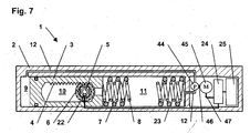
- FIG. 7 shows a drive device 1 with motorized opening assistance.
- the drive device 1 is constructed in principle as shown in Figure 1 Drive device; deviating from this is instead of the electrically controllable Valve in the overflow 12, a hydraulic pump 44 is arranged.
- the pump 44 is driven via a coupling 46 by an electric motor 45, wherein the electric motor 45 via an electrical line 47 to the controller 24 is connected.
- the electric motor 45 When manual opening of the wing, the force in a first opening angle portion starting from the closed position as low as possible be, the electric motor 45 via the controller 24 after it the manual opening of the wing connected to the drive device detected by a signal from the sensor 22, so controlled that the Hydraulic medium from the middle housing chamber 11 in the drawing in the on the opening of the wing enlarging, in the drawing left housing chamber 9 is promoted.
- the control the pump 44 may, depending on the opening speed and of the Opening position of the wing done. For this purpose, in the memory device of Control device 24 be deposited a movement profile. Based on the Comparison of the actual wing movement with the stored movement profile the electric motor 45 of the pump 44 is activated.
- the pump 44 is reversible, i. in It is then possible to operate the pump 44 which can be operated in both directions of flow possible that the electric motor 45 of the pump 44 shortly before reaching the open position of the wing - again, if necessary, taking into account the movement speed of the grand piano - is reversed, i. that the conveying direction the pump 44 is reversed. This is an opening damping function realizable.
- a hold-open function is feasible.
- a valve not shown here to realize a hold-open function by shutting off the overflow channel 12 may be arranged.
- the pump 44 acts in the manner of a turbine, i.e. the flowing hydraulic medium causes the pump 44 to rotate.
- the electric motor 45 acts as a regenerative brake, the Braking action by the controller 24 based on the comparison of actual wing movement with the stored motion profile regulated becomes.
- An "Endschlag" function is feasible by the braking effect shortly before Reaching the closed position of the wing withdrawn or canceled becomes.
- the pump 44 can be reversed again, so they then the occurring during closing flow of the hydraulic medium and thus the mechanical energy storage in the sense of a reliable closure of the Wing supported.
Landscapes
- Power-Operated Mechanisms For Wings (AREA)
Abstract
Description
- Figur 1
- eine Antriebsvorrichtung mit hydraulischer Dämpfung in Schnittdarstellung;
- Figur 2
- eine Antriebsvorrichtung mit mechanischer Bremse (Dämpfung) in Schnittdarstellung;
- Figur 3
- eine Antriebsvorrichtung mit generatorischer Bremse (Dämpfung) in Schnittdarstellung;
- Figur 4
- die Öffnungswinkelteilbereiche eines an die Antriebsvorrichtung angeschlossenen Flügels in Draufsicht;
- Figur 5
- eine Antriebsvorrichtung mit zusätzlicher Gehäusekammerdruckerfassung in Schnittdarstellung;
- Figur 6
- eine Antriebsvorrichtung mit motorischer Schließkraftverstellung in Schnittdarstellung;
- Figur 7
- eine Antriebsvorrichtung mit elektrohydraulischer Pumpe in Schnittdarstellung.
- 1
- Antriebsvorrichtung
- 2
- Gehäuse
- 3
- Kolben
- 4
- Verzahnung
- 5
- Abtriebsglied
- 6
- Ritzel
- 7
- Energiespeicher
- 8
- Energiespeicher
- 9
- Gehäusekammer
- 10
- Innenraum
- 11
- Gehäusekammer
- 12
- Überströmkanal
- 20
- Ventil
- 21
- elektrische Leitung
- 22
- Sensor
- 23
- elektrische Leitung
- 24
- Steuerungseinrichtung
- 25
- Energiespeicher
- 26
- elektrische Leitung
- 27
- Bremseinrichtung
- 28
- elektrische Leitung
- 29
- Generator
- 30
- elektrische Leitung
- 31
- Getriebe
- 32
- Flügel
- 33
- Gelenk
- 34
- Türzarge
- 35
- Wand
- 36
- Elektromotor
- 37
- Gewindespindel
- 38
- Federteller
- 39
- elektrische Leitung
- 40
- Drucksensor
- 41
- elektrische Leitung
- 42
- Drucksensor
- 43
- elektrische Leitung
- 44
- Pumpe
- 45
- Elektromotor
- 46
- Kupplung
- 47
- elektrische Leitung
- A
- Gesamtöffnungswinkel
- B
- Öffnungswinkelteilbereich
- C
- Öffnungswinkelteilbereich
- D
- Öffnungswinkelteilbereich
- E
- Öffnungswinkelteilbereich
- F
- Öffnungswinkelteilbereich
Claims (17)
- Antriebsvorrichtung (1) für einen beweglichen Flügel, insbesondere für eine Tür oder ein Fenster,
mit mindestens einem Energiespeicher (7, 8), durch dessen Energieabgabe der Flügel bewegt wird,
wobei der Energiespeicher (7, 8) durch eine Beeinflussungseinrichtung in seiner Energieabgabe beeinflussbar ist,
dadurch gekennzeichnet, dass die Beeinflussungseinrichtung ein elektrisch ansteuerbares Beeinflussungselement (20, 27, 29) aufweist,
wobei die Bewegung des Flügels (32) direkt oder indirekt durch einen Sensor (22) erfasst wird, dessen Ausgangssignal einem Eingang einer Steuerungseinrichtung (24) zugeleitet wird, welche das Beeinflussungselement (20, 27, 29) steuert, und
wobei die Steuerungseinrichtung (24) so ausgebildet ist, dass das Beeinflussungselement (20, 27, 29) abhängig von der Bewegung des Flügels (32) in seinem Einfluss auf die Energieabgabe des Energiespeichers veränderbar ist. - Antriebsvorrichtung nach Anspruch 1,
dadurch gekennzeichnet, dass die Steuerungseinrichtung (24) eine Rechnereinrichtung und eine Speichereinrichtung sowie einen elektrischen Energiespeicher (25) aufweist, wobei die Speichereinrichtung so ausgebildet ist, dass in ihr die Betriebsparameter der Antriebsvorrichtung (1) speicherbar sind, und wobei die Rechnereinrichtung so ausgebildet ist, dass in ihr Vergleiche der gespeicherten Betriebsparameter der Antriebsvorrichtung (1) mit den gemessenen Signalen des Sensors (22) durchführbar sind. - Antriebsvorrichtung nach Anspruch 2,
dadurch gekennzeichnet, dass die Steuerungseinrichtung (24) so ausgebildet ist, dass beim Auftreten von Abweichungen der tatsächlichen Betriebsstati der Antriebsvorrichtung (1) von den gespeicherten Betriebsparametern eine automatische Reaktion im Sinne einer Regelung erfolgt, insbesondere durch entsprechendes Ansteuern der Beeinflussungseinrichtung. - Antriebsvorrichtung nach Anspruch 1,
dadurch gekennzeichnet, dass die Antriebsvorrichtung (1 ) eine Schließdämpfung aufweist, wobei jedem Öffnungswinkel des Flügels (32) ein einstellbarer und änderbarer Wert der Schließdämpfung zuordenbar ist. - Antriebsvorrichtung nach Anspruch 4,
dadurch gekennzeichnet, dass die Antriebsvorrichtüng (1) eine Endschlagfunktion aufweist, wobei die Schließdämpfung kurz vor Erreichen der Geschlossenlage des Flügels (32) verringert oder aufgehoben wird und wobei der Öffnungswinkel des Flügels (32), bei der die Endschlagfunktion einsetzt, einstellbar und änderbar ist. - Antriebsvorrichtung nach Anspruch 1,
dadurch gekennzeichnet, dass die Antriebsvorrichtung (1 ) eine einstellbare Öffnungsdämpfung aufweist. - Antriebsvorrichtung nach Anspruch 1,
dadurch gekennzeichnet, dass die Antriebsvorrichtung (1.) eine Feststellfunktion aüfweist, wobei der Feststellwinkel des Flügels (32) einstellbar und änderbar ist. - Antriebsvorrichtung nach Anspruch, 1,
dadurch gekennzeichnet, dass der Sensor (22) als Drehgeber ausgebildet ist. - Antriebsvorrichtung nach Anspruch 1,
dadurch gekennzeichnet, dass der Sensor (22) als linearer Weggeber ausgebildet ist. - Antriebsvorrichtung nach Anspruch 1,
dadurch gekennzeichnet, dass der Sensor als Drucksensor (40, 42) ausgebildet ist. - Antriebsvorrichtung nach Anspruch 1,
dadurch gekennzeichnet, dass der Sensor als Sensor für die Strömungsgeschwindigkeit des Hydraulikmediums ausgebildet ist. - Antriebsvorrichtung nach Anspruch 1,
dadurch gekennzeichnet, dass das Beeinflussungselement als elektrisch ansteuerbares Ventil (20) ausgebildet ist. - Antriebsvorrichtung nach Anspruch 1,
dadurch gekennzeichnet, dass das Beeinflussungselement als mechanische Bremseinrichtung (27) ausgebildet ist. - Antriebsvorrichtung nach Anspruch 1,
dadurch gekennzeichnet, dass das Beeinflussungselement als elektrischer Generator (29) ausgebildet ist. - Antriebsvorrichtung nach Anspruch 1,
dadurch gekennzeichnet, dass die Steuerungseinrichtung (24) elektrische Ein- und Ausgänge zum Anschluss externer elektrischer Elemente aufweist. - ; Antriebsvorrichtung nach Anspruch 1,
dadurch gekennzeichnet, dass ,die Antriebsvorrichtung (1) über eine Schnittstelle an eine externe Einrichtung zur Datenanzeige und/oder Dateneingabe anschließbar ist. - ; Antriebsvorrichtung nach Anspruch 1,
dadurch gekennzeichnet, dass die Antriebsvorrichtung (1) eine fremdkraftbetätigte Einrichtung zur Verstellung der Federvorspannung aufweist.
Applications Claiming Priority (4)
| Application Number | Priority Date | Filing Date | Title |
|---|---|---|---|
| DE10209268 | 2002-03-01 | ||
| DE10209268 | 2002-03-01 | ||
| DE10259925A DE10259925A1 (de) | 2002-03-01 | 2002-12-20 | Türantrieb |
| DE10259925 | 2002-12-20 |
Publications (3)
| Publication Number | Publication Date |
|---|---|
| EP1340877A2 true EP1340877A2 (de) | 2003-09-03 |
| EP1340877A3 EP1340877A3 (de) | 2007-08-22 |
| EP1340877B1 EP1340877B1 (de) | 2016-05-25 |
Family
ID=27735698
Family Applications (1)
| Application Number | Title | Priority Date | Filing Date |
|---|---|---|---|
| EP03004486.1A Revoked EP1340877B1 (de) | 2002-03-01 | 2003-02-28 | Türantrieb |
Country Status (4)
| Country | Link |
|---|---|
| US (1) | US7571515B2 (de) |
| EP (1) | EP1340877B1 (de) |
| CN (1) | CN1291127C (de) |
| CA (1) | CA2420748C (de) |
Cited By (13)
| Publication number | Priority date | Publication date | Assignee | Title |
|---|---|---|---|---|
| DE202010000905U1 (de) * | 2010-01-14 | 2011-06-01 | Jansen Entwicklungs GmbH & Co. KG, 26903 | Brandschutzeinrichtung |
| EP2547854A1 (de) * | 2010-03-17 | 2013-01-23 | Yale Security Inc | Türsteuerungsvorrichtung |
| FR2978477A1 (fr) * | 2011-07-26 | 2013-02-01 | Somfy Sas | Systeme et procede d'ouverture et de fermeture de battants, installation equipee d'un tel systeme, et ensemble domotique comprenant au moins deux installations |
| FR2978478A1 (fr) * | 2011-07-26 | 2013-02-01 | Somfy Sas | Systeme autonome d'ouverture et de fermeture de battants, et installation equipee d'un tel systeme |
| EP2716849A1 (de) * | 2007-04-24 | 2014-04-09 | Yale Security Inc | Türschliesseranordnung |
| EP2436863A3 (de) * | 2010-09-30 | 2014-06-18 | Dorma GmbH&Co. Kg | Elektrischer Türbetätiger |
| IT201600081638A1 (it) * | 2016-08-03 | 2018-02-03 | Mypro Res S R L | Dispositivo di smorzamento. |
| EP2650461B1 (de) | 2012-04-13 | 2019-03-20 | GU Automatic GmbH | Einrichtung zur Schließfolgeregelung einer selbstschließenden zweiflügligen Tür sowie ein Verfahren zur Schließregelung einer selbstschließenden Tür und Feuerschutztür mit einer Einrichtung zur Schließfolgeregelung |
| EP3461979A1 (de) * | 2017-09-27 | 2019-04-03 | dormakaba Deutschland GmbH | Auslegungsverfahren zum auslegen einer dämpfungsvorrichtung eines türschliessers, computerprogrammprodukt, dämpfungsvorrichtung sowie türschliesser |
| EP3543965A1 (de) * | 2018-03-22 | 2019-09-25 | dormakaba Deutschland GmbH | Schlossanordnung |
| DE102018206576A1 (de) * | 2018-04-27 | 2019-10-31 | Geze Gmbh | Türschließer, elektrohydraulisches Dämpfungsmodul und Verfahren zum Beeinflussen einer Antriebsbewegung eines Türschließers |
| US11187022B1 (en) | 2001-07-13 | 2021-11-30 | Steven M. Hoffberg | Intelligent door restraint |
| EP4116533A1 (de) * | 2021-07-05 | 2023-01-11 | GEZE GmbH | Türsystem und verfahren zum betreiben eines solchen |
Families Citing this family (50)
| Publication number | Priority date | Publication date | Assignee | Title |
|---|---|---|---|---|
| DE102004002655A1 (de) * | 2004-01-16 | 2005-08-18 | Dorma Gmbh + Co. Kg | Türschließer mit Antrieb |
| DE102004061624C5 (de) * | 2004-12-17 | 2011-02-03 | Dorma Gmbh + Co. Kg | Türantrieb, insbesondere Drehtürantieb |
| DE102004062235A1 (de) * | 2004-12-23 | 2006-07-13 | BSH Bosch und Siemens Hausgeräte GmbH | Einbauhaushaltsgerät |
| GB0523497D0 (en) * | 2005-11-18 | 2005-12-28 | Forde Anthony F | Safety door wedge |
| ITRM20060085U1 (it) * | 2006-05-17 | 2007-11-18 | Findisa S R L | Sistema oleodinamico a bassa tensione a controllo elettronico di movimentazione di chiusure automatiche |
| DE102006026008A1 (de) * | 2006-06-01 | 2007-12-06 | Dorma Gmbh + Co. Kg | Türantrieb mit während der Türbewegung veränderbarer Federvorspannung |
| WO2008137550A2 (en) * | 2007-05-03 | 2008-11-13 | Wabtec Holding Corp. | Locking mechanism for pneumatic differential engine for power-operated doors |
| US7795746B2 (en) * | 2008-05-01 | 2010-09-14 | Robert Bosch Gmbh | Apparatus and method for generating power for a low current device |
| WO2011117083A1 (en) * | 2010-03-24 | 2011-09-29 | Assa Abloy Ip Ab | Power efficient sliding door |
| US8773237B2 (en) | 2010-04-16 | 2014-07-08 | Yale Security Inc. | Door closer with teach mode |
| US8415902B2 (en) | 2010-04-16 | 2013-04-09 | Yale Security Inc. | Door closer with calibration mode |
| US8547046B2 (en) * | 2010-04-16 | 2013-10-01 | Yale Security Inc. | Door closer with self-powered control unit |
| US8527101B2 (en) | 2010-04-16 | 2013-09-03 | Yale Security Inc. | Door closer assembly |
| US8779713B2 (en) | 2010-04-16 | 2014-07-15 | Yale Security Inc. | Door closer with dynamically adjustable latch region parameters |
| US8564235B2 (en) | 2010-04-16 | 2013-10-22 | Yale Security Inc. | Self-adjusting door closer |
| DE102010030304B4 (de) * | 2010-06-21 | 2015-05-28 | Geze Gmbh | Antrieb zum Öffnen und/oder Schließen eines beweglichen Flügels einer Tür oder eines Fensters |
| CN102287109A (zh) * | 2011-06-22 | 2011-12-21 | 肇庆市志盛门控五金有限公司 | 一种具有延时开门功能的闭门器 |
| DE102011055491A1 (de) * | 2011-11-18 | 2013-05-23 | Dorma Gmbh + Co. Kg | Servotürschließer |
| US10236801B2 (en) * | 2012-05-08 | 2019-03-19 | Schlage Lock Company Llc | Door closer system |
| DE102012111539A1 (de) * | 2012-11-28 | 2014-05-28 | Dorma Gmbh + Co. Kg | Türbetätiger |
| KR101418582B1 (ko) * | 2012-12-03 | 2014-07-10 | (주) 다원에스디에스 | 도어 클로저 |
| CN103397827B (zh) * | 2013-08-27 | 2016-01-20 | 长城汽车股份有限公司 | 车辆 |
| US8966712B1 (en) * | 2013-12-31 | 2015-03-03 | Chia-Chu Yu | Door operator |
| USD744315S1 (en) * | 2014-04-08 | 2015-12-01 | Sugatsune Kogyo Co., Ltd. | Door closer |
| DK2933416T3 (da) * | 2014-04-15 | 2019-08-19 | Geze Gmbh | Dørdrev |
| CN104989209B (zh) * | 2014-12-01 | 2016-07-13 | 上海品贵国际贸易有限公司 | 具速度调整功能的机轴自动归位装置 |
| GB201513274D0 (en) | 2015-07-28 | 2015-09-09 | Freeman & Pardoe Ltd | A door closer |
| US11105135B2 (en) | 2015-12-31 | 2021-08-31 | Larson Manufacturing Company Of South Dakota, Llc | Hydraulic door closer with fluid overflow chamber |
| US10370885B1 (en) * | 2015-12-31 | 2019-08-06 | Larson Manufacturing Company Of South Dakota | Hydraulic door closer with fluid overflow chamber |
| CN205400375U (zh) * | 2016-01-05 | 2016-07-27 | 希美克(广州)实业有限公司 | 一种具有高温减压功能的液压闭门器 |
| DE102016207029A1 (de) * | 2016-04-26 | 2017-10-26 | Geze Gmbh | Antriebseinheit und Verfahren zum Schliessen eines Flügels einer Tür oder eines Fensters |
| EP4350648A2 (de) | 2016-05-16 | 2024-04-10 | Schlage Lock Company LLC | Kommunikation eines türschliessers |
| DE102016210598A1 (de) * | 2016-06-15 | 2018-01-04 | Geze Gmbh | Antrieb für einen tür- oder fensterflügel |
| DE102016210780B4 (de) * | 2016-06-16 | 2018-08-02 | Geze Gmbh | Bremsvorrichtung für einen beweglichen Türflügel und korrespondierende Tür |
| DE102016221339A1 (de) * | 2016-10-28 | 2018-05-03 | Geze Gmbh | Überwachungssystem |
| DE102017201955A1 (de) * | 2017-02-08 | 2018-08-09 | Geze Gmbh | Bremsvorrichtung |
| DE102017201953A1 (de) | 2017-02-08 | 2018-08-09 | Geze Gmbh | Antriebseinrichtung für einen Tür- oder Fensterflügel |
| CN107091034A (zh) * | 2017-06-28 | 2017-08-25 | 太仓荣中机电科技有限公司 | 可调速自动闭门器 |
| US20190112849A1 (en) * | 2017-10-16 | 2019-04-18 | Magna Closures Inc. | Power-operated variable force door check mechanism for a vehicular closure system |
| DE102018200700B4 (de) * | 2018-01-17 | 2020-03-26 | Geze Gmbh | Bremsvorrichtung für einen beweglichen Türflügel und Türschließer mit einer solchen Bremsvorrichtung |
| DE102018200730B4 (de) * | 2018-01-17 | 2019-09-05 | Geze Gmbh | Bremsvorrichtung für einen beweglichen Türflügel und Türschließer mit einer solchen Bremsvorrichtung |
| DE102018200946A1 (de) * | 2018-01-22 | 2019-07-25 | Geze Gmbh | Bremsvorrichtung für einen beweglichen türflügel und türschliesser mit einer solchen bremsvorrichtung |
| DE102018111287A1 (de) * | 2018-05-11 | 2019-11-14 | ABUS August Bremicker Söhne KG | Bremsscheibenschloss |
| DE102018210278B4 (de) * | 2018-06-25 | 2021-03-18 | Geze Gmbh | Hydräülisch,gedämpfter Antrieb für einen Tür- oder Fensterflügel |
| GB2577541B (en) * | 2018-09-28 | 2023-06-14 | Assa Abloy Ltd | Adjustable door-closer |
| CA3151016A1 (en) * | 2019-09-12 | 2021-03-18 | Dustin LAWHON | Door closer with power close |
| EP4031738A1 (de) * | 2019-09-16 | 2022-07-27 | ASSA ABLOY Entrance Systems AB | Eingangssystem und verfahren zum betrieb eines solchen eingangssystems |
| CN112654230B (zh) * | 2020-12-24 | 2022-03-11 | 湖南铁路科技职业技术学院 | 一种用于提高dc/dc变换器硬件装配稳定性的组装装置 |
| US11519212B2 (en) * | 2021-02-24 | 2022-12-06 | Schlage Lock Company Llc | Modular add-on devices for door closers |
| CN115199166B (zh) * | 2022-06-02 | 2023-07-14 | 中国长江电力股份有限公司 | 两级活塞液压阻尼延时闭门器 |
Citations (10)
| Publication number | Priority date | Publication date | Assignee | Title |
|---|---|---|---|---|
| US4148111A (en) | 1977-11-30 | 1979-04-10 | Reading Door Closer Corp. | Temperature compensating hydraulic door closer |
| DE3423242C1 (de) | 1984-06-23 | 1985-11-07 | Dorma-Baubeschlag Gmbh & Co Kg, 5828 Ennepetal | Selbsttaetiger Tuerschliesser |
| DE9102344U1 (de) | 1991-02-28 | 1991-05-16 | Dorma Gmbh + Co. Kg, 5828 Ennepetal, De | |
| WO1992012318A1 (de) | 1991-01-08 | 1992-07-23 | record Türautomation GmbH | Elektromechanischer drehflügelantrieb für schwenkflügel von türen oder dergleichen |
| DE4231803A1 (de) | 1992-09-23 | 1994-03-24 | Dorma Gmbh & Co Kg | Diagnose- und Überwachungsverfahren zur Fehlererkennung, Statusreport und Parameteranpassung bei automatischen Türen und Toren |
| EP0662560A1 (de) | 1994-01-10 | 1995-07-12 | Schlage Lock Company | Tür-Regelung mit einem automatisch einstellbaren Dämpfungsvermögen |
| EP0764752A2 (de) | 1995-09-23 | 1997-03-26 | GEZE GmbH & Co. | Schliessvorrichtung für einen Flügel eines Fensters, einer Tür oder dergleichen |
| US5678451A (en) | 1994-08-02 | 1997-10-21 | Thomson Multimedia S.A. | Jog and shuttle controls for electronic or electrical devices |
| US5687507A (en) | 1993-07-19 | 1997-11-18 | Dorma Door Controls Inc. | Apparatus for selective alteration of operating parameters of a door |
| DE19650569A1 (de) | 1996-12-06 | 1998-06-18 | Dorma Gmbh & Co Kg | Vorrichtung und Verfahren zur Ferndiagnose, Fernüberwachung und Ferninitialisierung von automatischen Türen, Türanlagen und Toranlagen |
Family Cites Families (36)
| Publication number | Priority date | Publication date | Assignee | Title |
|---|---|---|---|---|
| US3989287A (en) * | 1972-08-28 | 1976-11-02 | Keystone Industries, Inc. | Automotive vehicle door retarding and closing mechanism |
| US4040143A (en) | 1976-08-06 | 1977-08-09 | Schlage Lock Company | Releasable door hold-open device |
| CH635184A5 (de) * | 1978-12-22 | 1983-03-15 | Sulzer Ag | Dampferzeugeranlage. |
| JPS5854181A (ja) | 1981-09-28 | 1983-03-31 | ワイケイケイ株式会社 | 自動開閉扉の制御装置 |
| DE3204975C1 (de) * | 1982-02-12 | 1983-05-19 | Echt & Co, Nachf. Schulte Kg, 5750 Menden | Doppelflueglige Tuer mit Schliessfolgeregelung |
| EP0137861B1 (de) | 1983-10-13 | 1987-03-25 | Dorma Baubeschlag GmbH. & Co. KG | Selbsttätiger Türschliesser |
| GB2156950B (en) * | 1984-04-04 | 1988-01-13 | Newman Tonks Eng | Flow control valve and door closer incorporating such a valve |
| JPS62152914A (ja) * | 1985-12-26 | 1987-07-07 | Nippon Soken Inc | 走行路面状態検出装置 |
| FI78767C (fi) | 1987-07-09 | 1989-09-11 | Waertsilae Oy Ab | Foerfarande och arrangemang foer optimering av funktionen hos en doerrstaengare. |
| DE3742213C2 (de) * | 1987-12-12 | 1995-03-30 | Dorma Gmbh & Co Kg | Türschließer mit einer durch eine Federanordnung im Schließsinn belasteten Schließerwelle |
| US4878265A (en) * | 1988-09-07 | 1989-11-07 | Dorma Door Controls, Inc. | Hold-open mechanism for use with a door closer |
| US4979261A (en) * | 1989-06-05 | 1990-12-25 | Schlage Lock Company | Variable position door closer |
| US4995194A (en) * | 1990-03-27 | 1991-02-26 | Yale Security Inc. | Power-assist door closer |
| JPH049387U (de) * | 1990-05-15 | 1992-01-28 | ||
| DE4041925C1 (de) | 1990-12-27 | 1992-03-12 | Dorma-Glas Gesellschaft Fuer Glastuerbeschlaege Und -Konstruktionen Mbh, 4902 Bad Salzuflen, De | |
| US5243735A (en) | 1992-03-09 | 1993-09-14 | Thomas Industries, Inc. | Regenerative feedback door control device with one-way clutch |
| US5193647A (en) | 1992-03-23 | 1993-03-16 | Thomas Industries, Inc. | Easy opening door control device |
| DE4323150B4 (de) * | 1993-07-10 | 2004-09-23 | Geze Gmbh | Drehtürantrieb |
| US5913763A (en) | 1993-07-19 | 1999-06-22 | Dorma Door Controls, Inc. | Method for controlling the operational modes of a door in conjunction with a mechanical door control mechanism |
| CA2134016A1 (en) | 1994-01-07 | 1995-07-08 | Peter B. Bandy | Data storage device and method of operation |
| US5417011A (en) * | 1994-02-23 | 1995-05-23 | Keszthelyi; Laszlo | Door opening mechanism |
| DE19514610A1 (de) | 1994-04-25 | 1995-11-02 | Geze Gmbh & Co | Antrieb zum Öffnen und/oder Schließen eines Flügels, einer Tür, eines Fensters oder dergleichen |
| US5515649A (en) * | 1994-08-15 | 1996-05-14 | Gentleman Door Company | Automatic door operator |
| US5513467A (en) * | 1995-05-30 | 1996-05-07 | Schlage Lock Company | Linear drive power door operator |
| JP3254118B2 (ja) | 1995-10-13 | 2002-02-04 | リョービ株式会社 | ドアクローザにおける速度調整装置および速度調整方法 |
| DE19538482C1 (de) * | 1995-10-17 | 1997-02-06 | Dorma Gmbh & Co Kg | Hydraulischer Servotürschließer |
| US5850671A (en) * | 1996-03-01 | 1998-12-22 | Geze Gmbh & Co. | Door closer |
| US5746250A (en) * | 1996-03-08 | 1998-05-05 | Wick; John Leslie | Portable automatic sprinkling system |
| DE19626831C1 (de) * | 1996-07-04 | 1998-01-08 | Dorma Gmbh & Co Kg | Türschließer zur Erzeugung eines Übersetzungssprunges während der Schließphase |
| US6366080B1 (en) * | 1997-04-24 | 2002-04-02 | Trw Fahrwerksysteme Gmbh & Co. Kg | Sensor for sensing rotary movement including a stationary sensor unit and a rotatable sensor unit |
| US6138412A (en) * | 1997-04-25 | 2000-10-31 | Chase Industries, Inc. | Door opener and closer |
| DE19726021A1 (de) | 1997-06-19 | 1998-12-24 | Geze Gmbh & Co | Antrieb für einen Flügel einer Tür, eines Fensters doer dergleichen |
| ES2157670T3 (es) * | 1997-08-01 | 2001-08-16 | Geze Gmbh | Accionamiento para una puerta. |
| GB9811398D0 (en) * | 1998-05-27 | 1998-07-22 | Pbt Limited | Spool valve |
| US6675535B2 (en) * | 2000-12-22 | 2004-01-13 | Richard Armstrong | Remote control door operating and coupling assembly |
| US6751909B2 (en) * | 2001-02-06 | 2004-06-22 | The Stanley Works | Automatic door control system |
-
2003
- 2003-02-28 EP EP03004486.1A patent/EP1340877B1/de not_active Revoked
- 2003-02-28 CN CNB031285333A patent/CN1291127C/zh not_active Expired - Fee Related
- 2003-03-03 CA CA2420748A patent/CA2420748C/en not_active Expired - Lifetime
- 2003-03-03 US US10/377,027 patent/US7571515B2/en not_active Expired - Lifetime
Patent Citations (10)
| Publication number | Priority date | Publication date | Assignee | Title |
|---|---|---|---|---|
| US4148111A (en) | 1977-11-30 | 1979-04-10 | Reading Door Closer Corp. | Temperature compensating hydraulic door closer |
| DE3423242C1 (de) | 1984-06-23 | 1985-11-07 | Dorma-Baubeschlag Gmbh & Co Kg, 5828 Ennepetal | Selbsttaetiger Tuerschliesser |
| WO1992012318A1 (de) | 1991-01-08 | 1992-07-23 | record Türautomation GmbH | Elektromechanischer drehflügelantrieb für schwenkflügel von türen oder dergleichen |
| DE9102344U1 (de) | 1991-02-28 | 1991-05-16 | Dorma Gmbh + Co. Kg, 5828 Ennepetal, De | |
| DE4231803A1 (de) | 1992-09-23 | 1994-03-24 | Dorma Gmbh & Co Kg | Diagnose- und Überwachungsverfahren zur Fehlererkennung, Statusreport und Parameteranpassung bei automatischen Türen und Toren |
| US5687507A (en) | 1993-07-19 | 1997-11-18 | Dorma Door Controls Inc. | Apparatus for selective alteration of operating parameters of a door |
| EP0662560A1 (de) | 1994-01-10 | 1995-07-12 | Schlage Lock Company | Tür-Regelung mit einem automatisch einstellbaren Dämpfungsvermögen |
| US5678451A (en) | 1994-08-02 | 1997-10-21 | Thomson Multimedia S.A. | Jog and shuttle controls for electronic or electrical devices |
| EP0764752A2 (de) | 1995-09-23 | 1997-03-26 | GEZE GmbH & Co. | Schliessvorrichtung für einen Flügel eines Fensters, einer Tür oder dergleichen |
| DE19650569A1 (de) | 1996-12-06 | 1998-06-18 | Dorma Gmbh & Co Kg | Vorrichtung und Verfahren zur Ferndiagnose, Fernüberwachung und Ferninitialisierung von automatischen Türen, Türanlagen und Toranlagen |
Cited By (21)
| Publication number | Priority date | Publication date | Assignee | Title |
|---|---|---|---|---|
| US11187022B1 (en) | 2001-07-13 | 2021-11-30 | Steven M. Hoffberg | Intelligent door restraint |
| US9399884B2 (en) | 2007-04-24 | 2016-07-26 | Yale Security Inc. | Door closer assembly |
| EP2716849A1 (de) * | 2007-04-24 | 2014-04-09 | Yale Security Inc | Türschliesseranordnung |
| DE102011008423A1 (de) | 2010-01-14 | 2012-01-12 | Jansen Entwicklungs Gmbh & Co. Kg | Brandschutzeinrichtung |
| DE202010000905U1 (de) * | 2010-01-14 | 2011-06-01 | Jansen Entwicklungs GmbH & Co. KG, 26903 | Brandschutzeinrichtung |
| US9163446B2 (en) | 2010-03-17 | 2015-10-20 | Yale Security Inc. | Door control apparatus |
| EP2547854A1 (de) * | 2010-03-17 | 2013-01-23 | Yale Security Inc | Türsteuerungsvorrichtung |
| AU2011227577B2 (en) * | 2010-03-17 | 2016-04-14 | Yale Security Inc. | Door control apparatus |
| EP2436863A3 (de) * | 2010-09-30 | 2014-06-18 | Dorma GmbH&Co. Kg | Elektrischer Türbetätiger |
| EP2551434A3 (de) * | 2011-07-26 | 2013-03-13 | Somfy SAS | System und Verfahren zur Öffnung und Schließung von Klappflügeln, mit einem solchen System ausgestattete Anlage und Heimanlage, die mindestens zwei Anlagen umfasst |
| EP2551435A3 (de) * | 2011-07-26 | 2013-03-13 | Somfy SAS | Autonomes Öffnungs- und Schließsystem für Klappflügel, und mit einem solchen System ausgestattete Anlage |
| FR2978478A1 (fr) * | 2011-07-26 | 2013-02-01 | Somfy Sas | Systeme autonome d'ouverture et de fermeture de battants, et installation equipee d'un tel systeme |
| FR2978477A1 (fr) * | 2011-07-26 | 2013-02-01 | Somfy Sas | Systeme et procede d'ouverture et de fermeture de battants, installation equipee d'un tel systeme, et ensemble domotique comprenant au moins deux installations |
| EP2650461B1 (de) | 2012-04-13 | 2019-03-20 | GU Automatic GmbH | Einrichtung zur Schließfolgeregelung einer selbstschließenden zweiflügligen Tür sowie ein Verfahren zur Schließregelung einer selbstschließenden Tür und Feuerschutztür mit einer Einrichtung zur Schließfolgeregelung |
| IT201600081638A1 (it) * | 2016-08-03 | 2018-02-03 | Mypro Res S R L | Dispositivo di smorzamento. |
| WO2018025105A1 (en) * | 2016-08-03 | 2018-02-08 | Mypro Research S.R.L. | Damping device |
| EP3461979A1 (de) * | 2017-09-27 | 2019-04-03 | dormakaba Deutschland GmbH | Auslegungsverfahren zum auslegen einer dämpfungsvorrichtung eines türschliessers, computerprogrammprodukt, dämpfungsvorrichtung sowie türschliesser |
| EP3543965A1 (de) * | 2018-03-22 | 2019-09-25 | dormakaba Deutschland GmbH | Schlossanordnung |
| EP3543965B1 (de) | 2018-03-22 | 2022-07-06 | dormakaba Deutschland GmbH | Schlossanordnung und verfahren zur überprüfung einer schlossanordnung |
| DE102018206576A1 (de) * | 2018-04-27 | 2019-10-31 | Geze Gmbh | Türschließer, elektrohydraulisches Dämpfungsmodul und Verfahren zum Beeinflussen einer Antriebsbewegung eines Türschließers |
| EP4116533A1 (de) * | 2021-07-05 | 2023-01-11 | GEZE GmbH | Türsystem und verfahren zum betreiben eines solchen |
Also Published As
| Publication number | Publication date |
|---|---|
| CA2420748C (en) | 2011-06-28 |
| CN1291127C (zh) | 2006-12-20 |
| US7571515B2 (en) | 2009-08-11 |
| CA2420748A1 (en) | 2003-09-01 |
| EP1340877A3 (de) | 2007-08-22 |
| CN1448608A (zh) | 2003-10-15 |
| EP1340877B1 (de) | 2016-05-25 |
| US20030213092A1 (en) | 2003-11-20 |
Similar Documents
| Publication | Publication Date | Title |
|---|---|---|
| EP1340877B1 (de) | Türantrieb | |
| DE10259925A1 (de) | Türantrieb | |
| EP3325750B1 (de) | Türkomponente mit einer steuerbaren dämpfereinrichtung | |
| EP0662185B1 (de) | Schwenktürantrieb | |
| EP1982030B1 (de) | Verfahren und vorrichtung zum steuern der schliessbewegung eines karosseriebauteils für fahrzeuge | |
| DE4214998A1 (de) | Torantrieb und Verfahren zum Betreiben eines Torantriebes | |
| EP0086267B1 (de) | Elektropneumatische Türsteuerung | |
| DE102006057889B4 (de) | Vorrichtung zum Öffnen und Schließeneines elektrischen Bauteils bei einem Hindernis | |
| EP3361028A1 (de) | Antriebseinheit | |
| DE102006057680B3 (de) | Verfahren und Vorrichtung zum Öffnen und Schließen eines elektrischen Bauteils bei einem Hindernis | |
| EP1487078B1 (de) | Verfahren zum Initialisieren einer fremdkraftbetätigten Verstellvorrichtung und Vorrichtung zur Durchführung des Initialisierungsverfahrens | |
| EP1913222B1 (de) | Verfahren zur positionierung einer beweglichen einheit in einem kraftfahrzeug | |
| EP2122098B1 (de) | Verfahren zur ansteuerung eines stellelements | |
| EP0767288B1 (de) | Antriebssystem für Verschliesselemente | |
| DE102015104818B4 (de) | Verfahren zum Betreiben eines Türantriebs, Türantriebssteuerung, Türantrieb und Drehflügeltür | |
| EP3361034A1 (de) | Feststell- und/oder notöffnungsanlage | |
| EP2206867B1 (de) | Türbetätiger zur betätigung eines türblattes | |
| DE102015104825A1 (de) | Verfahren zum Betreiben eines Türantriebs, Türantriebssteuerung, Türantrieb und Drehflügeltür | |
| DE102021207029A1 (de) | Türsystem und Verfahren zum Betreiben eines solchen | |
| CH690370A5 (de) | Türantrieb. | |
| EP3652100A1 (de) | Automatische tür, insbesondere automatische aufzugtür |
Legal Events
| Date | Code | Title | Description |
|---|---|---|---|
| PUAI | Public reference made under article 153(3) epc to a published international application that has entered the european phase |
Free format text: ORIGINAL CODE: 0009012 |
|
| AK | Designated contracting states |
Kind code of ref document: A2 Designated state(s): AT BE BG CH CY CZ DE DK EE ES FI FR GB GR HU IE IT LI LU MC NL PT SE SI SK TR |
|
| AX | Request for extension of the european patent |
Extension state: AL LT LV MK RO |
|
| PUAL | Search report despatched |
Free format text: ORIGINAL CODE: 0009013 |
|
| AK | Designated contracting states |
Kind code of ref document: A3 Designated state(s): AT BE BG CH CY CZ DE DK EE ES FI FR GB GR HU IE IT LI LU MC NL PT SE SI SK TR |
|
| AX | Request for extension of the european patent |
Extension state: AL LT LV MK RO |
|
| 17P | Request for examination filed |
Effective date: 20080131 |
|
| AKX | Designation fees paid |
Designated state(s): AT BE BG CH CY CZ DE DK EE ES FI FR GB GR HU IE IT LI LU MC NL PT SE SI SK TR |
|
| 17Q | First examination report despatched |
Effective date: 20081209 |
|
| GRAP | Despatch of communication of intention to grant a patent |
Free format text: ORIGINAL CODE: EPIDOSNIGR1 |
|
| INTG | Intention to grant announced |
Effective date: 20160113 |
|
| GRAS | Grant fee paid |
Free format text: ORIGINAL CODE: EPIDOSNIGR3 |
|
| GRAA | (expected) grant |
Free format text: ORIGINAL CODE: 0009210 |
|
| STAA | Information on the status of an ep patent application or granted ep patent |
Free format text: STATUS: THE PATENT HAS BEEN GRANTED |
|
| AK | Designated contracting states |
Kind code of ref document: B1 Designated state(s): AT BE BG CH CY CZ DE DK EE ES FI FR GB GR HU IE IT LI LU MC NL PT SE SI SK TR |
|
| REG | Reference to a national code |
Ref country code: GB Ref legal event code: FG4D Free format text: NOT ENGLISH |
|
| REG | Reference to a national code |
Ref country code: CH Ref legal event code: EP |
|
| REG | Reference to a national code |
Ref country code: IE Ref legal event code: FG4D Free format text: LANGUAGE OF EP DOCUMENT: GERMAN Ref country code: AT Ref legal event code: REF Ref document number: 802483 Country of ref document: AT Kind code of ref document: T Effective date: 20160615 |
|
| REG | Reference to a national code |
Ref country code: DE Ref legal event code: R096 Ref document number: 50315472 Country of ref document: DE |
|
| REG | Reference to a national code |
Ref country code: NL Ref legal event code: MP Effective date: 20160525 |
|
| PG25 | Lapsed in a contracting state [announced via postgrant information from national office to epo] |
Ref country code: NL Free format text: LAPSE BECAUSE OF FAILURE TO SUBMIT A TRANSLATION OF THE DESCRIPTION OR TO PAY THE FEE WITHIN THE PRESCRIBED TIME-LIMIT Effective date: 20160525 Ref country code: FI Free format text: LAPSE BECAUSE OF FAILURE TO SUBMIT A TRANSLATION OF THE DESCRIPTION OR TO PAY THE FEE WITHIN THE PRESCRIBED TIME-LIMIT Effective date: 20160525 |
|
| PG25 | Lapsed in a contracting state [announced via postgrant information from national office to epo] |
Ref country code: GR Free format text: LAPSE BECAUSE OF FAILURE TO SUBMIT A TRANSLATION OF THE DESCRIPTION OR TO PAY THE FEE WITHIN THE PRESCRIBED TIME-LIMIT Effective date: 20160826 Ref country code: ES Free format text: LAPSE BECAUSE OF FAILURE TO SUBMIT A TRANSLATION OF THE DESCRIPTION OR TO PAY THE FEE WITHIN THE PRESCRIBED TIME-LIMIT Effective date: 20160525 Ref country code: PT Free format text: LAPSE BECAUSE OF FAILURE TO SUBMIT A TRANSLATION OF THE DESCRIPTION OR TO PAY THE FEE WITHIN THE PRESCRIBED TIME-LIMIT Effective date: 20160926 Ref country code: SE Free format text: LAPSE BECAUSE OF FAILURE TO SUBMIT A TRANSLATION OF THE DESCRIPTION OR TO PAY THE FEE WITHIN THE PRESCRIBED TIME-LIMIT Effective date: 20160525 |
|
| PG25 | Lapsed in a contracting state [announced via postgrant information from national office to epo] |
Ref country code: EE Free format text: LAPSE BECAUSE OF FAILURE TO SUBMIT A TRANSLATION OF THE DESCRIPTION OR TO PAY THE FEE WITHIN THE PRESCRIBED TIME-LIMIT Effective date: 20160525 Ref country code: SK Free format text: LAPSE BECAUSE OF FAILURE TO SUBMIT A TRANSLATION OF THE DESCRIPTION OR TO PAY THE FEE WITHIN THE PRESCRIBED TIME-LIMIT Effective date: 20160525 Ref country code: CZ Free format text: LAPSE BECAUSE OF FAILURE TO SUBMIT A TRANSLATION OF THE DESCRIPTION OR TO PAY THE FEE WITHIN THE PRESCRIBED TIME-LIMIT Effective date: 20160525 Ref country code: DK Free format text: LAPSE BECAUSE OF FAILURE TO SUBMIT A TRANSLATION OF THE DESCRIPTION OR TO PAY THE FEE WITHIN THE PRESCRIBED TIME-LIMIT Effective date: 20160525 |
|
| REG | Reference to a national code |
Ref country code: FR Ref legal event code: PLFP Year of fee payment: 15 |
|
| REG | Reference to a national code |
Ref country code: DE Ref legal event code: R026 Ref document number: 50315472 Country of ref document: DE |
|
| PLBI | Opposition filed |
Free format text: ORIGINAL CODE: 0009260 |
|
| PLAX | Notice of opposition and request to file observation + time limit sent |
Free format text: ORIGINAL CODE: EPIDOSNOBS2 |
|
| 26 | Opposition filed |
Opponent name: ASSA ABLOY SICHERHEITSTECHNIK GMBH Effective date: 20170227 |
|
| PG25 | Lapsed in a contracting state [announced via postgrant information from national office to epo] |
Ref country code: SI Free format text: LAPSE BECAUSE OF FAILURE TO SUBMIT A TRANSLATION OF THE DESCRIPTION OR TO PAY THE FEE WITHIN THE PRESCRIBED TIME-LIMIT Effective date: 20160525 Ref country code: BE Free format text: LAPSE BECAUSE OF NON-PAYMENT OF DUE FEES Effective date: 20170228 |
|
| PLBB | Reply of patent proprietor to notice(s) of opposition received |
Free format text: ORIGINAL CODE: EPIDOSNOBS3 |
|
| PG25 | Lapsed in a contracting state [announced via postgrant information from national office to epo] |
Ref country code: MC Free format text: LAPSE BECAUSE OF FAILURE TO SUBMIT A TRANSLATION OF THE DESCRIPTION OR TO PAY THE FEE WITHIN THE PRESCRIBED TIME-LIMIT Effective date: 20160525 |
|
| REG | Reference to a national code |
Ref country code: CH Ref legal event code: PL |
|
| PG25 | Lapsed in a contracting state [announced via postgrant information from national office to epo] |
Ref country code: LI Free format text: LAPSE BECAUSE OF NON-PAYMENT OF DUE FEES Effective date: 20170228 Ref country code: CH Free format text: LAPSE BECAUSE OF NON-PAYMENT OF DUE FEES Effective date: 20170228 |
|
| REG | Reference to a national code |
Ref country code: IE Ref legal event code: MM4A |
|
| PG25 | Lapsed in a contracting state [announced via postgrant information from national office to epo] |
Ref country code: LU Free format text: LAPSE BECAUSE OF NON-PAYMENT OF DUE FEES Effective date: 20170228 |
|
| REG | Reference to a national code |
Ref country code: BE Ref legal event code: MM Effective date: 20170228 |
|
| REG | Reference to a national code |
Ref country code: FR Ref legal event code: PLFP Year of fee payment: 16 |
|
| PG25 | Lapsed in a contracting state [announced via postgrant information from national office to epo] |
Ref country code: IE Free format text: LAPSE BECAUSE OF NON-PAYMENT OF DUE FEES Effective date: 20170228 |
|
| REG | Reference to a national code |
Ref country code: AT Ref legal event code: MM01 Ref document number: 802483 Country of ref document: AT Kind code of ref document: T Effective date: 20170228 |
|
| PG25 | Lapsed in a contracting state [announced via postgrant information from national office to epo] |
Ref country code: AT Free format text: LAPSE BECAUSE OF NON-PAYMENT OF DUE FEES Effective date: 20170228 |
|
| PLCK | Communication despatched that opposition was rejected |
Free format text: ORIGINAL CODE: EPIDOSNREJ1 |
|
| STAA | Information on the status of an ep patent application or granted ep patent |
Free format text: STATUS: THE PATENT HAS BEEN GRANTED |
|
| APBM | Appeal reference recorded |
Free format text: ORIGINAL CODE: EPIDOSNREFNO |
|
| APBP | Date of receipt of notice of appeal recorded |
Free format text: ORIGINAL CODE: EPIDOSNNOA2O |
|
| APAH | Appeal reference modified |
Free format text: ORIGINAL CODE: EPIDOSCREFNO |
|
| APBQ | Date of receipt of statement of grounds of appeal recorded |
Free format text: ORIGINAL CODE: EPIDOSNNOA3O |
|
| PG25 | Lapsed in a contracting state [announced via postgrant information from national office to epo] |
Ref country code: HU Free format text: LAPSE BECAUSE OF FAILURE TO SUBMIT A TRANSLATION OF THE DESCRIPTION OR TO PAY THE FEE WITHIN THE PRESCRIBED TIME-LIMIT; INVALID AB INITIO Effective date: 20030228 |
|
| PG25 | Lapsed in a contracting state [announced via postgrant information from national office to epo] |
Ref country code: BG Free format text: LAPSE BECAUSE OF FAILURE TO SUBMIT A TRANSLATION OF THE DESCRIPTION OR TO PAY THE FEE WITHIN THE PRESCRIBED TIME-LIMIT Effective date: 20160525 |
|
| PG25 | Lapsed in a contracting state [announced via postgrant information from national office to epo] |
Ref country code: CY Free format text: LAPSE BECAUSE OF NON-PAYMENT OF DUE FEES Effective date: 20160525 |
|
| PG25 | Lapsed in a contracting state [announced via postgrant information from national office to epo] |
Ref country code: TR Free format text: LAPSE BECAUSE OF FAILURE TO SUBMIT A TRANSLATION OF THE DESCRIPTION OR TO PAY THE FEE WITHIN THE PRESCRIBED TIME-LIMIT Effective date: 20160525 |
|
| REG | Reference to a national code |
Ref country code: DE Ref legal event code: R103 Ref document number: 50315472 Country of ref document: DE Ref country code: DE Ref legal event code: R064 Ref document number: 50315472 Country of ref document: DE |
|
| APBU | Appeal procedure closed |
Free format text: ORIGINAL CODE: EPIDOSNNOA9O |
|
| PGFP | Annual fee paid to national office [announced via postgrant information from national office to epo] |
Ref country code: GB Payment date: 20220223 Year of fee payment: 20 Ref country code: DE Payment date: 20220228 Year of fee payment: 20 |
|
| PGFP | Annual fee paid to national office [announced via postgrant information from national office to epo] |
Ref country code: IT Payment date: 20220218 Year of fee payment: 20 Ref country code: FR Payment date: 20220216 Year of fee payment: 20 |
|
| RDAF | Communication despatched that patent is revoked |
Free format text: ORIGINAL CODE: EPIDOSNREV1 |
|
| STAA | Information on the status of an ep patent application or granted ep patent |
Free format text: STATUS: PATENT REVOKED |
|
| RDAG | Patent revoked |
Free format text: ORIGINAL CODE: 0009271 |
|
| REG | Reference to a national code |
Ref country code: FI Ref legal event code: MGE |
|
| 27W | Patent revoked |
Effective date: 20220412 |
|
| GBPR | Gb: patent revoked under art. 102 of the ep convention designating the uk as contracting state |
Effective date: 20220412 |
|
| REG | Reference to a national code |
Ref country code: AT Ref legal event code: MA03 Ref document number: 802483 Country of ref document: AT Kind code of ref document: T Effective date: 20220412 |