EP1313117A2 - Lichtbogenlöschanordnung für ein elektronisches Schaltgerät - Google Patents
Lichtbogenlöschanordnung für ein elektronisches Schaltgerät Download PDFInfo
- Publication number
- EP1313117A2 EP1313117A2 EP02024168A EP02024168A EP1313117A2 EP 1313117 A2 EP1313117 A2 EP 1313117A2 EP 02024168 A EP02024168 A EP 02024168A EP 02024168 A EP02024168 A EP 02024168A EP 1313117 A2 EP1313117 A2 EP 1313117A2
- Authority
- EP
- European Patent Office
- Prior art keywords
- arc
- plate
- arrangement according
- extinguishing
- quenching
- Prior art date
- Legal status (The legal status is an assumption and is not a legal conclusion. Google has not performed a legal analysis and makes no representation as to the accuracy of the status listed.)
- Granted
Links
Images



Classifications
-
- H—ELECTRICITY
- H01—ELECTRIC ELEMENTS
- H01H—ELECTRIC SWITCHES; RELAYS; SELECTORS; EMERGENCY PROTECTIVE DEVICES
- H01H9/00—Details of switching devices, not covered by groups H01H1/00 - H01H7/00
- H01H9/30—Means for extinguishing or preventing arc between current-carrying parts
- H01H9/302—Means for extinguishing or preventing arc between current-carrying parts wherein arc-extinguishing gas is evolved from stationary parts
-
- H—ELECTRICITY
- H01—ELECTRIC ELEMENTS
- H01H—ELECTRIC SWITCHES; RELAYS; SELECTORS; EMERGENCY PROTECTIVE DEVICES
- H01H71/00—Details of the protective switches or relays covered by groups H01H73/00 - H01H83/00
- H01H71/02—Housings; Casings; Bases; Mountings
- H01H71/025—Constructional details of housings or casings not concerning the mounting or assembly of the different internal parts
-
- H—ELECTRICITY
- H01—ELECTRIC ELEMENTS
- H01H—ELECTRIC SWITCHES; RELAYS; SELECTORS; EMERGENCY PROTECTIVE DEVICES
- H01H73/00—Protective overload circuit-breaking switches in which excess current opens the contacts by automatic release of mechanical energy stored by previous operation of a hand reset mechanism
- H01H73/02—Details
- H01H73/18—Means for extinguishing or suppressing arc
-
- H—ELECTRICITY
- H01—ELECTRIC ELEMENTS
- H01H—ELECTRIC SWITCHES; RELAYS; SELECTORS; EMERGENCY PROTECTIVE DEVICES
- H01H9/00—Details of switching devices, not covered by groups H01H1/00 - H01H7/00
- H01H9/30—Means for extinguishing or preventing arc between current-carrying parts
- H01H9/34—Stationary parts for restricting or subdividing the arc, e.g. barrier plate
Definitions
- the invention relates to an arc extinguishing arrangement for an electrical switching device according to the preamble of claim 1.
- An electrical switching device comprises an insulating housing, which consists of a lower and an upper part is joined in a plane parallel to its broad sides, and Input and output connections, between which there is at least one current path a contact point, which is in the event of an overcurrent or a short-circuit current must be opened.
- a contact point which is in the event of an overcurrent or a short-circuit current must be opened.
- One in the contact point which is either a fixed one and a movable contact piece or two fixed spaced apart
- a contact point is preferably found in circuit breakers, the movable one Contact piece is arranged on a contact lever; preferably with motor protection switches there are two fixed contact pieces, which are connected using a contact bridge are bridged.
- At one contact point there is only an arc quenching plate package provided, whereas two such packages at the double contact point are provided.
- the arc quenching plate package has several arc quenching plates on which are kept at a distance from one another by means of insulating paper; by virtue of of the individual arc quenching plates, the arc is converted into small individual arcs divided, which creates an increased arc voltage, that of the mains voltage counteracts and which ensures a current limitation. The higher the number of Sheet, the greater the arc voltage can be.
- the gas pressure can be within of the quenching plate package can be increased, which also increases the arc voltage is increased because there is a gas atmosphere between the arc extinguishers with coating exists, which can serve to increase the existing arc voltage enlarge.
- the object of the invention is the arc extinguishing arrangement of the aforementioned Kind of improving even further.
- the outer periphery can protrude the outer circumference of the arc extinguishing plates and the one inner recess having.
- the inner recess have an inlet constriction area and an extended area, of which the Inlet area is open to the contact point.
- the conditions are within the arc quenching stack easier to control or the individual parameters can be coordinated more cheaply.
- An optimized gas pressure is generated within the arc quenching plate package be so that the arc voltage between the individual quenching plates increases without the arc returning to the contact point due to excessive gas pressure to be led. This ensures the stable burning of the arc within the arc quenching plate package more controllable, the arc voltage is increased and this limits the prospective short-circuit current better and safer.
- the material can be, for example, the plastic PA 6 or the plastic PA (6-6) are used, the outgassing of which is optimal for the purpose of arc extinguishing is.
- the inlet constriction area can be rectilinear Have boundary edges; but it could also be V-shaped to the contact point expand towards.
- the expanded area of the inner recess can be approximately rectangular or possibly also have an approximately circular inner contour.
- the inner recess has a keyhole shape.
- the at least one plate is like this attached that it limits the arc quenching plate package on one side.
- Another embodiment of the invention provides that the at least one Plate of insulating material completely or partially on the inside of at least one Part of the insulating housing of the electrical switching device is molded.
- a standard arc quenching plate package is used can be used in the housing so that the inside molded on the housing plate limits the arc quenching plate package on one side.
- the arc quenching plate package itself does not have to be changed because the plate made of insulating material is molded as part of the housing on the inside and is also made of the same material as the housing.
- the plate provides that the plate is along one parallel to its long sides and is divided into two halves between these dividing axes, each one half is integrally formed on the inside of one of the two insulating housing parts.
- the two plate parts When assembling the insulating housing, add from the upper and lower part the two plate parts then seamlessly along the division axis to the complete Plate together.
- the two plate parts fit together in such a way that from the joining of their outer contours, the inner contour of the inner recess forms in the plate.
- the particular advantage of the invention is that the switching capacity is improved and increased or the switch-off behavior is stabilized; beyond that the clearances and creepage distances in an arrangement with an arc quenching chamber between the contact pieces with an extension serving as a guardrail become.
- the invention can be used in all switching devices in which one at a Switching action arcing arcing is extinguished with a quenching device or to stabilize the arc at a certain point.
- FIG. 1 shows a circuit breaker 10 in which the invention is applied by way of example is.
- a circuit breaker 10 Within the circuit breaker 10 is only a schematic Switch lock 11 shown, the one hand with a switch toggle 12 and the other is coupled to a movable contact lever 13 on which a movable Contact piece 14 is attached.
- the circuit breaker 10 further includes an electromagnetic release 15, the armature 16 in the event of a short circuit spends the contact lever 13 in the open position.
- the plunger anchor 16 is also included the key switch 11 connected, via a lever 17, so that after opening of the contact lever 13, the key switch 11 keeps the contact lever open.
- the movable contact piece 14 interacts with a fixed contact piece 20 and when switching off, i.e. when the contact lever moves 13 clockwise, arises between the movable contact piece 14 and the fixed contact piece 20 an arc 21, the arc guide plates or rails 22 and a horn 23 is supplied to an arc-quenching plate packet 24.
- the Arc guide 22 is assigned to the movable contact piece 14, the arc horn 23 the fixed contact piece.
- the arc quenching plate packet 24 is shown in more detail in FIGS. 2 to 4. It owns several arc extinguishing plates 25, 11 in the embodiment according to FIG. 3, which, as can be seen from FIG. 2, have a substantially rectangular shape, an approximately V-shaped on the narrow side edge 26 facing the contact point 14, 20 Cutout 27 is provided, the parallel edges 28 and 29 open into the narrow side edge 26, and edges pointing towards one another in a V-shape 30 and 31.
- the tip of the V-shape of the cutout 27 has a nose 32, which points away from the contact point.
- the arc extinguisher pack 24 is from one Insulating paper 33 includes.
- each arc extinguishing sheet has a depression 36, 37 that is slight is greater than the thickness of the insulating paper 33 and lugs 38 and 39, which engage in corresponding openings 40 on the insulating paper 33 and thus for fixation the arc quenching plates 25 serve.
- the circumferential contour 42 of the circumferential contour of the quenching plates 25th corresponds; it has an inner recess 44 which has an inlet constriction area 45 and has an expanded area 46, the inlet throat area 45 opens in a V-shape towards the contact point.
- the V-shape is the V-shape Recess 27 adjusted.
- the plate 41 is made of plastic, preferably a gassing plastic, namely Ultramid (A3 Sk) or PA (6-6).
- FIG. 5 shows a plate 50 with a rectangular outer contour 51 with two parallel ones Long sides 52 and 53 and narrow side edges 54 running transversely thereto and 55 and an inner recess 56.
- the inner recess 56 has an inlet constriction area 57, which is open to the contact point 14, 20, and an expanded Area 58.
- Inlet frame area 57 has parallel inner edges that run parallel to the longitudinal edges 52 and 53; the inner contour of the extended area 58 is rectangular.
- the Inlet bottleneck area 56 and extended area 58 includes, through the closed Thin lines are meant to indicate that these areas are others Can have shapes.
- Fig. 6 shows a sectional view along the section line VI-VI of Fig. 5, with two side by side lying arc extinguishing plates 25 '25 ", between which the plate 50 is arranged.
- the arc 21 burns through the enlarged area 58 and acts on the material of the plate 50 so that it outgasses and a change in Atmosphere generated in the arc quenching chamber or a change in gas pressure.
- FIG. 9 shows a perspective top view of the inside of a part of the insulating material housing 10a.
- the receptacles for the different ones Components of the installation switching device which have already been described above, in Form of recesses and bulges of different geometries provided.
- the spaces between the ribs correspond to the thickness of the quenching plates of the quenching plate package, so that when inserting a quenching plate package into the receiving space 100, the quenching plates of the quenching plate stack between the ribs 106 find and guided there and are kept.
- the receiving space 100 is delimited by a half 150a formed on the inside of the housing part of an insulating Plate 150.
- the upper outer contour line 150b of plate half 150a is shaped so that when the outer contour line is mirrored, this and its mirror image become the inner contour line the recess 58, 46 of an insulating plate 50, 41 according to FIG.
- the mirror axis is an imaginary line 149 that is parallel to the projection line of the inner contour line 150b on the broad side of the housing part 10a and through the section furthest from the inside of the housing part 150c of the contour line 150b runs.
- FIG. 11 shows in cross-section the assignment of an arc-quenching plate stack 124 the insulating plate 141 molded onto the inside of the insulating material housing 124 in FIG. 11 corresponds to the arc quenching stack 24 built in Fig. 3. Identical parts are 100 in FIG. 11 with respect to FIG. 3 provided with increased reference numbers.
- the plate 141 in Fig. 10 consists of two Halves 141a and 141b, which are arranged in mirror image to the axis 149. Each of the both halves 141a and 141b is on one of the inner sides 10a, 10b of the insulating material housing formed.
- the peripheral contour 142 of the assembly of the insulating material resulting insulating plate 141 corresponds to the circumferential contour of the quenching plates 125; it has an inner recess1 44 which has an inlet constriction area 145 and includes an expanded area 146, the inlet throat area 145 opens in a V-shape towards the contact point.
- the V shape is the V shape the recess 27 in Fig. 2 adapted.
- the plate 141 like the plate 41, is made of plastic, preferably a gas Plastic, namely PA 6 or PA (6-6).
- the plate 141 in the same operation as the insulating housing and together with it in one Pieces are made and then consists of the same material as the insulating housing.
- FIG. 12 shows a plate 150, the outer and inner contours of which are similar to those plate 50 in Fig. 5; however, the plate 150 is made up of two mirror images Halves 150a and 150b formed, which touch each other on the mirror axis 149, each of the two halves 150a and 150b on the inside of one of the two insulating housing parts 10a, 10b is formed.
- the contour parts, side parts and inner recesses of plate 150 in FIG. 12 otherwise correspond to that of plate 50 in FIG. 5, the respective ones Reference numerals are 100 from those in FIG. 5 elevated.
- FIG. 13 corresponds to FIG. 6 and shows a sectional view along the section line XIII-XIII of Fig. 12, with two adjacent arc quenching plates 125 ' 125 "between which the plate 150 is arranged.
- the arc 121 burns through it and acts on the material of the plate 150, so that this outgasses and a change in the atmosphere in the arc quenching chamber or a change in the gas pressure generated.
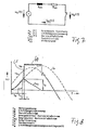
- FIG. 7 shows an equivalent circuit diagram of an arc quenching chamber with u s (t) as the driving voltage, u- b (t) as the arc voltage and i ks (t) as the short-circuit current.
- the designations I ks and r ks designate the inductance and the resistance, respectively.
- FIG. 8 shows a representation of the voltage u and the current i over time t.
- the dashed line u s is the mains voltage and u b is the arc voltage. It can be seen that after the contact point has been opened and the arc has entered the quenching chamber, the arc voltage oscillates in the region 60 until, after the arc has been extinguished (see further below), it returns to the line voltage u s curve.
- the arc voltage u b rises steeply in the region 61 in order to then pass into the region 60; this time period is referred to as the so-called arc voltage rise time.
- the current ip is limited, specifically according to the line i ks .
- the maximum value of the current i ks is the forward current that the switch still lets through after the short-circuit event occurs.
- the forward current i d is limited by means of the plates 41 and 50.
- the plate or plates can on the guardrail or on the fixed contact piece subsequent rail serving as a horn.
Landscapes
- Arc-Extinguishing Devices That Are Switches (AREA)
Abstract
Description
- Fig. 1
- eine Einsicht in ein elektrisches Schaltgerät,
- Fig. 2
- eine Aufsicht auf ein Lichtbogenlöschblech,
- Fig. 3
- eine Seitenansicht des Lichtbogenlöschpaketes, in den mehrere Löschbleche gemäß dem der Fig. 2 enthalten sind,
- Fig. 4
- eine erste Ausgestaltung einer Isolierplatte,
- Fig. 5
- eine zweite Ausführungsform der Isolierplatte,
- Fig. 6
- eine Schnittansicht gemäß Schnittlinie VI- VI der Fig. 5,
- Fig. 7
- ein Ersatzschaltbild einer Lichtbogenlöschkammer,
- Fig. 8
- ein Diagramm, in dem Strom und Spannung über der Zeit aufgetragen sind,
- Fig. 9
- eine Einsicht in ein Teil des Isolierstoffgehäuses mit angeformter Hälfte der Isolierplatte,
- Fig. 10
- eine dritte Ausführungsform der Isolierplatte, angeformt an die Innenseiten des Isolierstoffgehäuses,
- Fig. 11
- eine Seitenansicht des Löschblechpaketes, in dem mehrere Löschbleche gemäß dem der Fig. 2 enthalten sind und das seitlich durch eine isolierende Platte begrenzt wird, die an den Innenseiten des Isolierstoffgehäuses angeformt ist,
- Fig. 12
- eine vierte Ausführungsform der Isolierplatte und
- Fig. 13
- eine Schnittansicht gemäß Schnittlinie XIII - XIII der Fig. 12.
Claims (12)
- Lichtbogenlöschanordnung für ein elektrisches Schaltgerät, welches ein Isolierstoffgehäuse aufweist, das aus einem Unter- und einem Oberteil in einer Ebene parallel zu seinen Breitseiten zusammengefügt ist, mit einer Löschkammer, in der bei einer Schalthandlung zwischen einem feststehenden und einem beweglichen Kontaktstück ein Lichtbogen erzeugt wird, und mit einem mehrere Lichtbogenlöschbleche aufweisenden Lichtbogenlöschblechpaket, in das der Lichtbogen über Leitschienen hineingeführt wird, dadurch gekennzeichnet, daß im Lichtbogenlöschblechpaket (24) wenigstens eine Platte (41, 50) aus isolierendem Material angeordnet ist, deren Außenumfang dem Außenumfang der Lichtbogenlöschbleche (25) in etwa entspricht, und die eine Innenausnehmung (44, 56) aufweist.
- Lichtbogenlöschanordnung nach Anspruch 1, dadurch gekennzeichnet, daß die Innenausnehmung (44, 56) einen Einlaßengstellenbereich (45, 57) und einen erweiterten Bereich (46, 58) aufweist, von denen der Einlaßengstellenbereich (45, 57) zur Kontaktstelle (14, 20) offen ist.
- Lichtbogenlöschanordnung nach Anspruch 2, dadurch gekennzeichnet, daß der Einlaßengstellenbereich (57) geradlinige Begrenzungskanten aufweist.
- Lichtbogenlöschanordnung nach Anspruch 2, dadurch gekennzeichnet, daß der Einlaßengstellenbereich (45) sich V-förmig zur Kontaktstelle hin erweitert.
- Lichtbogenlöschanordnung nach einem der vorigen Ansprüche, dadurch gekennzeichnet, daß der erweiterte Bereich (58) eine etwa rechteckige Innenkontur aufweist.
- Lichtbogenlöschanordnung nach einem der Ansprüche 1 bis 4, dadurch gekennzeichnet, daß der erweiterte Bereich (46) eine etwa kreisförmige Innenkontur aufweist.
- Lichtbogenlöschanordnung nach einem der vorigen Ansprüche, dadurch gekennzeichnet, daß die Innenausnehmung eine Schlüssellochform aufweist.
- Lichtbogenlöschanordnung nach einem der vorigen Ansprüche, dadurch gekennzeichnet, daß die wenigstens eine Platte das Lichtbogenlöschblechpaket (24) einseitig begrenzt.
- Lichtbogenlöschanordnung nach einem der vorigen Ansprüche, dadurch gekennzeichnet, daß die wenigstens eine Platte ganz oder zumindest in Teilen an die Innenseite wenigstens eines Teiles des Isolierstoffgehäuses des elektrischen Schaltgerätes angeformt ist.
- Lichtbogenlöschanordnung nach einem der vorigen Ansprüche, dadurch gekennzeichnet, daß die wenigstens eine Platte entlang einer parallel zu ihren Längsseiten und zwischen diesen verlaufenden Teilungsachse in zwei Hälften geteilt ist, wobei je eine der beiden Hälften an der Innenseite eines der beiden Isolierstoffgehäuseteile angeformt ist, so daß die beiden Hälften nach Zusammenfügen des Isolierstoffgehäuses aus dem Unter- und Oberteil sich längs der Teilungsachse zu der wenigstens einen Platte zusammenfügen.
- Lichtbogenlöschanordnung nach einem der vorigen Ansprüche, dadurch gekennzeichnet, daß das isolierende Material ein gasender Kunststoff, vorzugsweise PA 6 oder PA (6-6), ist.
- Lichtbogenlöschanordnung nach einem der vorigen Ansprüche, dadurch gekennzeichnet, daß die isolierende Platte aus demselben Material besteht wie das Isolierstoffgehäuse.
Applications Claiming Priority (4)
| Application Number | Priority Date | Filing Date | Title |
|---|---|---|---|
| DE10156519 | 2001-11-16 | ||
| DE10156519 | 2001-11-16 | ||
| DE10242310A DE10242310A1 (de) | 2001-11-16 | 2002-09-12 | Lichtbogenlöschanordnung für ein elektrisches Schaltgerät |
| DE10242310 | 2002-09-12 |
Publications (3)
| Publication Number | Publication Date |
|---|---|
| EP1313117A2 true EP1313117A2 (de) | 2003-05-21 |
| EP1313117A3 EP1313117A3 (de) | 2005-02-16 |
| EP1313117B1 EP1313117B1 (de) | 2014-06-04 |
Family
ID=26010599
Family Applications (1)
| Application Number | Title | Priority Date | Filing Date |
|---|---|---|---|
| EP02024168.3A Expired - Lifetime EP1313117B1 (de) | 2001-11-16 | 2002-10-30 | Lichtbogenlöschanordnung für ein elektronisches Schaltgerät |
Country Status (2)
| Country | Link |
|---|---|
| US (1) | US6717090B2 (de) |
| EP (1) | EP1313117B1 (de) |
Cited By (2)
| Publication number | Priority date | Publication date | Assignee | Title |
|---|---|---|---|---|
| DE102010032715A1 (de) | 2010-07-29 | 2012-02-02 | Abb Ag | Lichtbogenlöscheinrichtung und Installationsschaltgerät mit einer Lichtbogenlöscheinrichtung |
| CN107731595A (zh) * | 2017-11-01 | 2018-02-23 | 苏州专创光电科技有限公司 | 一种基于齿轮的电力断路器的灭弧机构 |
Families Citing this family (21)
| Publication number | Priority date | Publication date | Assignee | Title |
|---|---|---|---|---|
| DE10013319C1 (de) * | 2000-03-17 | 2001-10-11 | Siemens Ag | Elektromagnetisches Schaltgerät, insbesondere Schütz, mit einer Kontaktbrückenträgerverriegelung |
| DE102005007303B4 (de) * | 2005-02-17 | 2013-03-21 | Abb Ag | Elektrisches Installationsgerät mit Lichtbogen-Vorkammerraum, Lichtbogenleitschienen und strombegrenzender Lichtbogenlöscheinrichtung |
| DE102005007282A1 (de) * | 2005-02-17 | 2006-08-24 | Abb Patent Gmbh | Elektrisches Installationsgerät mit Lichtbogen-Vorkammerraum, Vorkammerplatten und strombegrenzender Lichtbogenlöscheinrichtung |
| JP4827187B2 (ja) * | 2006-11-21 | 2011-11-30 | 富士電機株式会社 | 消弧用樹脂加工品、及びそれを用いた回路遮断器 |
| DE102008017868B3 (de) * | 2008-04-09 | 2009-12-24 | Abb Ag | Lichtbogenlöschblechanordnung für einen elektrischen Schalter |
| US8168911B2 (en) * | 2008-09-19 | 2012-05-01 | General Electric Company | Circuit breaker with improved arc quenching |
| DE102009053145A1 (de) * | 2009-11-05 | 2011-05-12 | Phoenix Contact Gmbh & Co. Kg | Überspannungsschutzelement |
| US8822866B2 (en) | 2010-04-19 | 2014-09-02 | Carling Technologies, Inc. | Circuit interrupter with enhanced arc quenching capabilities |
| US8866034B2 (en) | 2011-04-14 | 2014-10-21 | Carling Technologies, Inc. | Arc runner with integrated current path that develops a magnetic field to boost arc movement towards splitter plates |
| DE102012203598A1 (de) | 2012-03-07 | 2013-09-12 | Siemens Aktiengesellschaft | Befestigung von Löschblechen im Schaltpol eines Leistungsschalters |
| CN202816829U (zh) * | 2012-09-20 | 2013-03-20 | 上海诺雅克电气有限公司 | 一种高稳定性小型断路器 |
| CN105684118A (zh) * | 2013-10-29 | 2016-06-15 | 伊顿工业(奥地利)有限公司 | 灭弧室嵌入件 |
| JP6655792B2 (ja) * | 2014-05-12 | 2020-02-26 | パナソニックIpマネジメント株式会社 | 接点装置 |
| RU174487U1 (ru) * | 2017-04-13 | 2017-10-17 | Закрытое акционерное общество "Чебоксарский электроаппаратный завод" | Электромагнитный расцепитель максимального тока |
| CN107731596B (zh) * | 2017-11-01 | 2019-11-12 | 江苏一开电力科技有限公司 | 一种采用齿轮的电力断路器的灭弧机构 |
| CN107622897B (zh) * | 2017-11-01 | 2019-09-27 | 明光诚信电子贸易有限公司 | 一种采用弧形导轨的电力断路器的灭弧机构 |
| CN107622898B (zh) * | 2017-11-01 | 2019-09-27 | 明光诚信电子贸易有限公司 | 一种具有弧形导轨的电力断路器的灭弧机构 |
| CN107785197B (zh) * | 2017-11-01 | 2019-10-18 | 安徽龙和电力集团有限公司 | 一种基于弧形导轨的电力断路器的灭弧机构 |
| CN107742599B (zh) * | 2017-11-01 | 2020-03-31 | 国网湖北省电力有限公司随州供电公司 | 一种具有齿轮的电力断路器的灭弧机构 |
| US10504668B1 (en) | 2018-08-06 | 2019-12-10 | Carling Technologies, Inc. | Circuit breaker with snap action contacts |
| AU2018443896B2 (en) | 2018-09-25 | 2022-03-17 | Hager-Electro Sas | Electric arc-extinguishing device for an electrical protection apparatus, and electrical protection apparatus incorporating said device |
Citations (5)
| Publication number | Priority date | Publication date | Assignee | Title |
|---|---|---|---|---|
| US3706868A (en) | 1971-10-18 | 1972-12-19 | Square D Co | Arc chute |
| FR2348559A1 (fr) | 1976-04-15 | 1977-11-10 | Bbc Brown Boveri & Cie | Interrupteur automatique |
| EP0051756A1 (de) | 1980-11-08 | 1982-05-19 | BROWN, BOVERI & CIE Aktiengesellschaft | Lichtbogenlöscheinrichtung, insbesondere für einen Leitungsschutzschalter |
| DE3247681A1 (de) | 1982-12-23 | 1984-06-28 | Brown, Boveri & Cie Ag, 6800 Mannheim | Lichtbogenloeschkammer |
| FR2584230A1 (fr) | 1985-06-28 | 1987-01-02 | Merlin Gerin | Chambre d'extinction d'arc pour disjoncteur a basse tension a coupure dans l'air |
Family Cites Families (11)
| Publication number | Priority date | Publication date | Assignee | Title |
|---|---|---|---|---|
| US2704315A (en) * | 1951-12-18 | 1955-03-15 | Fed Electric Prod Co | Magnetic blow-out for circuit-breakers |
| US4143256A (en) * | 1977-03-17 | 1979-03-06 | General Electric Company | Arc chute having plates coated with weld deterent material |
| US4247746A (en) * | 1977-10-04 | 1981-01-27 | Dorman Smith Switchgear Limited | Electric circuit breaker |
| US4405847A (en) | 1980-12-23 | 1983-09-20 | Whipp & Bourme (1975) Limited | Arc chutes |
| GB8302615D0 (en) * | 1983-01-31 | 1983-03-02 | Whipp And Bourne 1975 Ltd | Arc splitter plates |
| AU563774B2 (en) * | 1985-03-26 | 1987-07-23 | Mitsubishi Denki Kabushiki Kaisha | Arc chute for circuit breaker |
| US4612426A (en) * | 1985-08-23 | 1986-09-16 | Westinghouse Electric Corp. | Arc chute assembly for circuit breaker |
| US4656446A (en) * | 1985-12-17 | 1987-04-07 | Westinghouse Electric Corp. | Current limiting circuit breaker with series double break contact system per pole |
| KR910000071B1 (ko) * | 1986-05-30 | 1991-01-19 | 미츠비시 덴키 가부시키가이샤 | 개폐기 |
| DE19518049A1 (de) | 1995-05-17 | 1996-11-21 | Abb Patent Gmbh | Lichtbogenlöscheinrichtung |
| DE19924414A1 (de) | 1999-05-27 | 2000-11-30 | Abb Patent Gmbh | Elektrisches Installationsgerät, insbesondere Leitungsschutzschalter |
-
2002
- 2002-10-30 EP EP02024168.3A patent/EP1313117B1/de not_active Expired - Lifetime
- 2002-11-18 US US10/298,430 patent/US6717090B2/en not_active Expired - Fee Related
Patent Citations (5)
| Publication number | Priority date | Publication date | Assignee | Title |
|---|---|---|---|---|
| US3706868A (en) | 1971-10-18 | 1972-12-19 | Square D Co | Arc chute |
| FR2348559A1 (fr) | 1976-04-15 | 1977-11-10 | Bbc Brown Boveri & Cie | Interrupteur automatique |
| EP0051756A1 (de) | 1980-11-08 | 1982-05-19 | BROWN, BOVERI & CIE Aktiengesellschaft | Lichtbogenlöscheinrichtung, insbesondere für einen Leitungsschutzschalter |
| DE3247681A1 (de) | 1982-12-23 | 1984-06-28 | Brown, Boveri & Cie Ag, 6800 Mannheim | Lichtbogenloeschkammer |
| FR2584230A1 (fr) | 1985-06-28 | 1987-01-02 | Merlin Gerin | Chambre d'extinction d'arc pour disjoncteur a basse tension a coupure dans l'air |
Cited By (5)
| Publication number | Priority date | Publication date | Assignee | Title |
|---|---|---|---|---|
| DE102010032715A1 (de) | 2010-07-29 | 2012-02-02 | Abb Ag | Lichtbogenlöscheinrichtung und Installationsschaltgerät mit einer Lichtbogenlöscheinrichtung |
| CN107731595A (zh) * | 2017-11-01 | 2018-02-23 | 苏州专创光电科技有限公司 | 一种基于齿轮的电力断路器的灭弧机构 |
| WO2019085361A1 (zh) * | 2017-11-01 | 2019-05-09 | 苏州专创光电科技有限公司 | 一种基于齿轮的电力断路器的灭弧机构 |
| CN110419089A (zh) * | 2017-11-01 | 2019-11-05 | 苏州专创光电科技有限公司 | 一种基于齿轮的电力断路器的灭弧机构 |
| CN110419089B (zh) * | 2017-11-01 | 2021-05-28 | 国网山东省电力公司临邑县供电公司 | 一种基于齿轮的电力断路器的灭弧机构 |
Also Published As
| Publication number | Publication date |
|---|---|
| US6717090B2 (en) | 2004-04-06 |
| US20030094439A1 (en) | 2003-05-22 |
| EP1313117A3 (de) | 2005-02-16 |
| EP1313117B1 (de) | 2014-06-04 |
Similar Documents
| Publication | Publication Date | Title |
|---|---|---|
| EP1313117A2 (de) | Lichtbogenlöschanordnung für ein elektronisches Schaltgerät | |
| DE10356271B4 (de) | Schaltgerät | |
| EP2061053A2 (de) | Schaltgerät für Gleichstrom-Anwendungen | |
| DE10242310A1 (de) | Lichtbogenlöschanordnung für ein elektrisches Schaltgerät | |
| EP3048626A1 (de) | Schaltgerät mit permanentmagnetischer lichtbogenlöschung | |
| EP2443710B1 (de) | Hörnerfunkenstrecke mit deionkammer | |
| EP2747109B1 (de) | Schaltgerät | |
| DE10118746B4 (de) | Verfahren zum Betreiben eines Schaltgerätes mit einem zuschaltbaren Strombegrenzer und zugehörige Anordnung | |
| DE3413555C2 (de) | ||
| EP2555217A1 (de) | Strombegrenzungssystem | |
| DE3908102A1 (de) | Selbstschalter, insbesondere leitungsschutzschalter | |
| DE69932493T2 (de) | Elektrisches Schaltgerät mit einem geschlitzten Kontakt | |
| EP3138111B1 (de) | Schaltgerät mit lichtbogenlöschvorrichtung | |
| EP2030211A1 (de) | Leistungsschalter oder leitungsschutzschalter | |
| DE2508299A1 (de) | Elektrisches schaltgeraet | |
| DE69401605T2 (de) | Elektrischer Schutzschalter mit elektrodynamischer Kontaktabstossung und mit Doppellöschkammern | |
| EP1302957B1 (de) | NH-Kontaktanordnung | |
| DE4243537B4 (de) | Verfahren zum Schalten eines Sicherungslasttrenners und Sicherungslasttrenner hierzu | |
| DE102005007303B4 (de) | Elektrisches Installationsgerät mit Lichtbogen-Vorkammerraum, Lichtbogenleitschienen und strombegrenzender Lichtbogenlöscheinrichtung | |
| EP0746863B1 (de) | Kontaktsystem für ein elektromagnetisches schaltgerät mit schnellauslöser | |
| EP1722384B1 (de) | Elektrisches Installationsgerät mit Lichtbogen-Vorkammerraum, Vorkammerplatten und strombegrenzender Lichtbogenlöscheinrichtung | |
| DE60032414T2 (de) | Elektrisches Schaltgerät mit einem Schaltstück, das mit einem Funkenfänger ausgerüstet ist | |
| EP3891773B1 (de) | Bidirektional schaltendes schütz mit z-förmiger kontaktbrücke | |
| DE2826243A1 (de) | Elektrisches schaltgeraet | |
| DE10119626A1 (de) | Installationsschaltgerät |
Legal Events
| Date | Code | Title | Description |
|---|---|---|---|
| PUAI | Public reference made under article 153(3) epc to a published international application that has entered the european phase |
Free format text: ORIGINAL CODE: 0009012 |
|
| AK | Designated contracting states |
Designated state(s): AT BE BG CH CY CZ DE DK EE ES FI FR GB GR IE IT LI LU MC NL PT SE SK TR |
|
| AX | Request for extension of the european patent |
Extension state: AL LT LV MK RO SI |
|
| PUAL | Search report despatched |
Free format text: ORIGINAL CODE: 0009013 |
|
| AK | Designated contracting states |
Kind code of ref document: A3 Designated state(s): AT BE BG CH CY CZ DE DK EE ES FI FR GB GR IE IT LI LU MC NL PT SE SK TR |
|
| AX | Request for extension of the european patent |
Extension state: AL LT LV MK RO SI |
|
| 17P | Request for examination filed |
Effective date: 20050222 |
|
| AKX | Designation fees paid |
Designated state(s): DE FR GB IT |
|
| 17Q | First examination report despatched |
Effective date: 20100505 |
|
| RAP1 | Party data changed (applicant data changed or rights of an application transferred) |
Owner name: ABB AG |
|
| GRAP | Despatch of communication of intention to grant a patent |
Free format text: ORIGINAL CODE: EPIDOSNIGR1 |
|
| INTG | Intention to grant announced |
Effective date: 20140212 |
|
| GRAS | Grant fee paid |
Free format text: ORIGINAL CODE: EPIDOSNIGR3 |
|
| GRAA | (expected) grant |
Free format text: ORIGINAL CODE: 0009210 |
|
| AK | Designated contracting states |
Kind code of ref document: B1 Designated state(s): DE FR GB IT |
|
| REG | Reference to a national code |
Ref country code: GB Ref legal event code: FG4D Free format text: NOT ENGLISH |
|
| REG | Reference to a national code |
Ref country code: DE Ref legal event code: R096 Ref document number: 50215933 Country of ref document: DE Effective date: 20140717 |
|
| REG | Reference to a national code |
Ref country code: DE Ref legal event code: R097 Ref document number: 50215933 Country of ref document: DE |
|
| PLBE | No opposition filed within time limit |
Free format text: ORIGINAL CODE: 0009261 |
|
| STAA | Information on the status of an ep patent application or granted ep patent |
Free format text: STATUS: NO OPPOSITION FILED WITHIN TIME LIMIT |
|
| 26N | No opposition filed |
Effective date: 20150305 |
|
| REG | Reference to a national code |
Ref country code: DE Ref legal event code: R097 Ref document number: 50215933 Country of ref document: DE Effective date: 20150305 |
|
| GBPC | Gb: european patent ceased through non-payment of renewal fee |
Effective date: 20141030 |
|
| PG25 | Lapsed in a contracting state [announced via postgrant information from national office to epo] |
Ref country code: GB Free format text: LAPSE BECAUSE OF NON-PAYMENT OF DUE FEES Effective date: 20141030 |
|
| REG | Reference to a national code |
Ref country code: FR Ref legal event code: PLFP Year of fee payment: 14 |
|
| PGFP | Annual fee paid to national office [announced via postgrant information from national office to epo] |
Ref country code: IT Payment date: 20151028 Year of fee payment: 14 |
|
| REG | Reference to a national code |
Ref country code: FR Ref legal event code: PLFP Year of fee payment: 15 |
|
| REG | Reference to a national code |
Ref country code: FR Ref legal event code: PLFP Year of fee payment: 16 |
|
| PG25 | Lapsed in a contracting state [announced via postgrant information from national office to epo] |
Ref country code: IT Free format text: LAPSE BECAUSE OF NON-PAYMENT OF DUE FEES Effective date: 20161030 |
|
| REG | Reference to a national code |
Ref country code: FR Ref legal event code: PLFP Year of fee payment: 17 |
|
| REG | Reference to a national code |
Ref country code: DE Ref legal event code: R081 Ref document number: 50215933 Country of ref document: DE Owner name: ABB SCHWEIZ AG, CH Free format text: FORMER OWNER: ABB AG, 68309 MANNHEIM, DE |
|
| PGFP | Annual fee paid to national office [announced via postgrant information from national office to epo] |
Ref country code: DE Payment date: 20211020 Year of fee payment: 20 |
|
| PGFP | Annual fee paid to national office [announced via postgrant information from national office to epo] |
Ref country code: FR Payment date: 20211021 Year of fee payment: 20 |
|
| REG | Reference to a national code |
Ref country code: DE Ref legal event code: R071 Ref document number: 50215933 Country of ref document: DE |