EP1306251A1 - Store à enrouler divisé pour une fenêtre de véhicule - Google Patents
Store à enrouler divisé pour une fenêtre de véhicule Download PDFInfo
- Publication number
- EP1306251A1 EP1306251A1 EP02022610A EP02022610A EP1306251A1 EP 1306251 A1 EP1306251 A1 EP 1306251A1 EP 02022610 A EP02022610 A EP 02022610A EP 02022610 A EP02022610 A EP 02022610A EP 1306251 A1 EP1306251 A1 EP 1306251A1
- Authority
- EP
- European Patent Office
- Prior art keywords
- roller blind
- winding shaft
- edge
- web
- winding
- Prior art date
- Legal status (The legal status is an assumption and is not a legal conclusion. Google has not performed a legal analysis and makes no representation as to the accuracy of the status listed.)
- Granted
Links
Images


Classifications
-
- B—PERFORMING OPERATIONS; TRANSPORTING
- B60—VEHICLES IN GENERAL
- B60J—WINDOWS, WINDSCREENS, NON-FIXED ROOFS, DOORS, OR SIMILAR DEVICES FOR VEHICLES; REMOVABLE EXTERNAL PROTECTIVE COVERINGS SPECIALLY ADAPTED FOR VEHICLES
- B60J1/00—Windows; Windscreens; Accessories therefor
- B60J1/20—Accessories, e.g. wind deflectors, blinds
- B60J1/2011—Blinds; curtains or screens reducing heat or light intensity
- B60J1/2013—Roller blinds
- B60J1/2019—Roller blinds powered, e.g. by electric, hydraulic or pneumatic actuators
- B60J1/2022—Roller blinds powered, e.g. by electric, hydraulic or pneumatic actuators with screw rods or extensible rods acting on the draw bar for pushing or push-pulling
-
- B—PERFORMING OPERATIONS; TRANSPORTING
- B60—VEHICLES IN GENERAL
- B60J—WINDOWS, WINDSCREENS, NON-FIXED ROOFS, DOORS, OR SIMILAR DEVICES FOR VEHICLES; REMOVABLE EXTERNAL PROTECTIVE COVERINGS SPECIALLY ADAPTED FOR VEHICLES
- B60J1/00—Windows; Windscreens; Accessories therefor
- B60J1/20—Accessories, e.g. wind deflectors, blinds
- B60J1/2011—Blinds; curtains or screens reducing heat or light intensity
- B60J1/2013—Roller blinds
- B60J1/2019—Roller blinds powered, e.g. by electric, hydraulic or pneumatic actuators
- B60J1/2025—Roller blinds powered, e.g. by electric, hydraulic or pneumatic actuators with flexible actuating elements connected to the draw bar for pulling only, e.g. cords, wires or cables
-
- B—PERFORMING OPERATIONS; TRANSPORTING
- B60—VEHICLES IN GENERAL
- B60J—WINDOWS, WINDSCREENS, NON-FIXED ROOFS, DOORS, OR SIMILAR DEVICES FOR VEHICLES; REMOVABLE EXTERNAL PROTECTIVE COVERINGS SPECIALLY ADAPTED FOR VEHICLES
- B60J1/00—Windows; Windscreens; Accessories therefor
- B60J1/20—Accessories, e.g. wind deflectors, blinds
- B60J1/2011—Blinds; curtains or screens reducing heat or light intensity
- B60J1/2013—Roller blinds
- B60J1/2019—Roller blinds powered, e.g. by electric, hydraulic or pneumatic actuators
- B60J1/2027—Roller blinds powered, e.g. by electric, hydraulic or pneumatic actuators with a buckle-proof guided flexible actuating element acting on the draw bar for pushing or push-pulling, e.g. a Bowden cable
-
- B—PERFORMING OPERATIONS; TRANSPORTING
- B60—VEHICLES IN GENERAL
- B60J—WINDOWS, WINDSCREENS, NON-FIXED ROOFS, DOORS, OR SIMILAR DEVICES FOR VEHICLES; REMOVABLE EXTERNAL PROTECTIVE COVERINGS SPECIALLY ADAPTED FOR VEHICLES
- B60J1/00—Windows; Windscreens; Accessories therefor
- B60J1/20—Accessories, e.g. wind deflectors, blinds
- B60J1/2011—Blinds; curtains or screens reducing heat or light intensity
- B60J1/2013—Roller blinds
- B60J1/2066—Arrangement of blinds in vehicles
- B60J1/2069—Arrangement of blinds in vehicles of multiple blinds, e.g. more than one blind per window or per actuation system
-
- B—PERFORMING OPERATIONS; TRANSPORTING
- B60—VEHICLES IN GENERAL
- B60J—WINDOWS, WINDSCREENS, NON-FIXED ROOFS, DOORS, OR SIMILAR DEVICES FOR VEHICLES; REMOVABLE EXTERNAL PROTECTIVE COVERINGS SPECIALLY ADAPTED FOR VEHICLES
- B60J1/00—Windows; Windscreens; Accessories therefor
- B60J1/20—Accessories, e.g. wind deflectors, blinds
- B60J1/2011—Blinds; curtains or screens reducing heat or light intensity
- B60J1/2013—Roller blinds
- B60J1/2066—Arrangement of blinds in vehicles
- B60J1/2072—Blinds with inclined or vertical orientation of the winding axis
-
- B—PERFORMING OPERATIONS; TRANSPORTING
- B60—VEHICLES IN GENERAL
- B60J—WINDOWS, WINDSCREENS, NON-FIXED ROOFS, DOORS, OR SIMILAR DEVICES FOR VEHICLES; REMOVABLE EXTERNAL PROTECTIVE COVERINGS SPECIALLY ADAPTED FOR VEHICLES
- B60J1/00—Windows; Windscreens; Accessories therefor
- B60J1/20—Accessories, e.g. wind deflectors, blinds
- B60J1/2011—Blinds; curtains or screens reducing heat or light intensity
- B60J1/2013—Roller blinds
- B60J1/2066—Arrangement of blinds in vehicles
- B60J1/2075—Arrangement of blinds in vehicles specially adapted for fixed windows
-
- B—PERFORMING OPERATIONS; TRANSPORTING
- B60—VEHICLES IN GENERAL
- B60J—WINDOWS, WINDSCREENS, NON-FIXED ROOFS, DOORS, OR SIMILAR DEVICES FOR VEHICLES; REMOVABLE EXTERNAL PROTECTIVE COVERINGS SPECIALLY ADAPTED FOR VEHICLES
- B60J1/00—Windows; Windscreens; Accessories therefor
- B60J1/20—Accessories, e.g. wind deflectors, blinds
- B60J1/2011—Blinds; curtains or screens reducing heat or light intensity
- B60J1/2013—Roller blinds
- B60J1/2066—Arrangement of blinds in vehicles
- B60J1/2086—Arrangement of blinds in vehicles specially adapted for openable windows, e.g. side window
Definitions
- DE 10 05 970 is a roller blind for windows in doors known from motor vehicles.
- the roller blind described there has a rotatably mounted below the window sill Winding shaft with a roller blind on one edge is attached.
- the roller blind is on her other from the edge remote from the winding shaft is attached to a tension rod and runs through a slot in the lower window parapet. Winding up the roller blind the winding shaft happens while using a spring motor pulling off with the help of two linear thrust members takes place that are sufficiently resistant to buckling.
- the push links are in the door using one engine housed.
- the push links will driven by so-called SUFLEXwellen®, that is bendable linear elements on the outside are provided with a screw. This results in a kind of helical rack that fits in an output gear of a gear motor engages. Both Push elements are driven synchronously.
- the pull-out rod is one or guided on both sides in guide rails, and the thrust links run stiffly in the guide rail.
- the rear one is also known Open side window.
- Open side window In the case of motor vehicles, the rear one is also known Open side window. However, it can usually not be opened over the entire length because otherwise the sunken pane with the one corresponding to the wheel arch Recess on the door would collide. That's why it will rear side window of the door through a web into an Essentially rectangular and one in the broadest sense divided triangular part.
- the disc in a rectangular shape Part can be sunk while the disc in triangular part cannot be opened.
- roller blind covers both Window sections. Such coverage of both parts requires a certain window geometry.
- roller blind device for large split windows of motor vehicles to create without the space required for the drive to enlarge significantly.
- this object is the roller blind device solved with the features of claim 1.
- each winding shaft has its own Roller blind connected, which means different winding lengths and / or directions are possible.
- a common drive device for both winding shafts provided through which the blinds either in terms of extending or retracting together are to be operated.
- the other, opposite Direction of movement is one for each Roller blind or winding shaft specific drive device accomplished.
- here is one in mechanical Meaning common drive device, in the mechanical parts of the drive device for both Roller blinds are used.
- All linear actuators are made by set a common electric motor in motion.
- Another variant provides for one of the winding shafts to couple a gearbox that rotates the Converts the winding shaft into a linear movement.
- the output link This gear engages on the free edge of the roller blind the other winding shaft to both in this way Move blinds synchronously.
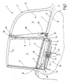
- Figure 1 shows in a highly schematic view the new double roller blind in connection with a right rear Side door 1 of a car sedan.
- the view illustrates the inside facing the vehicle occupant.
- the door 1 is partially in the area of its interior trim 2 broken up to reveal the essence of the invention to be let.
- the door 1 has one of one in its upper region Window frame 3 enclosed window that through a central web 4 in a front window section 5 and a rear window section 6 is divided.
- the rear window section 6 is from a lower window edge 7 a curved rear window edge 8 and a straight edge of the window that is vertical runs and is hidden in the figure by other parts. In this way, the rear window section 6 has a in the broadest sense about a triangular shape.
- the section 5 is largely rectangular and is front and rear by a window edge 9, a window edge 11 and an upper window edge 12 limited while the bottom edge of the window in the illustration is covered. It runs approximately in extension of the Lower window edge 7.
- the door trim 2 forms after the lower window edge 7 inside to a window parapet 12 that below the lower window edge 7 and to the left of the window section 5 can be seen.
- the window frame 3 covered with an inner panel 13 which around to show the essence of the invention by some Make also broke up.
- winding shaft 14 rotatably mounted below the window section 5 .
- the winding shaft 14 runs with it Axis roughly parallel to the bottom edge of the window, which is not visible of a window section 5.
- Storage facilities for the winding shaft 14 are known per se and in FIG. 1 Not shown for reasons of clarity.
- the winding shaft 14 is by means of a spring motor serving coil spring, which is indicated at 15, in biased in one direction.
- the spring motor 15 is for this housed in a known manner in the tubular winding shaft 14 and coupled at one end to the winding shaft 14. The other end of the spring motor 15 is corresponding on the adjacent bearing block for the winding shaft 14 anchored.
- the blind sheet 16 is cut in a way that the window section 15 completely covered.
- the blind sheet 16 runs through one when extended Slit through, which is in the broken away part of the door lining 2 is located.
- a drive device 19 available around the roller blind 16 against the force of the spring motor Subtract 15 from the winding shaft 14. Belongs to the drive device 19 a geared motor 21, on the output shaft of a gear 22 sits non-rotatably. The gear 22 meshes on opposite Sides with two serving as flexible push links Suflex waves 23 and 24 through corresponding guide channels are guided tangentially to the gear 22. On the gearbox close to the left and right two guide tubes 25 and 26 through which the two thrust links 23 and 24 are kink-resistant to just below the lower edge of the window of the window section 5 are guided.
- Each guide tube 25, 26 ends approximately just next to that End of the tie rod 18.
- Figure 3 shows the guide on an enlarged scale the pull rod 18 and the structure of the push member 23 and their interaction with the tie rod 18.
- the guide tube goes below the window parapet 12 26 into a laterally slotted guide rail 27 about.
- the guide rail 27 has the shape of a substantially cylindrical tube and is continuously on its side facing the window section 5 with a continuous longitudinal slot 28 provided.
- the clear expanse the guide rail 27 corresponds to the inside width of the Guide ear 26.
- the pull rod 18 is also tubular and in it is a guide member 29 with a guide pin 31.
- the free end of the guide pin carries one in Diameter larger ball 32 that slides inside the guide rail 27 is received and by the Slot 28 can not escape.
- the push member 23 is made of a flexible soul 33 and a wire-shaped coil 34 applied thereon together.
- the helix 34 is firmly connected to the core 33, so that it turns into a kind of endless screw.
- the spiral acts as a tooth, making the thrust link like a flexible Rack acts, the helical teeth on all sides wearing.
- the gear wheel 22 is adapted to the pitch of the helix 34, so that the push member 23 form-fitting with the as Tooth-acting helix 34 with the gear 22 in engagement stands.
- the guide rail 27 is opposite the window edge 9 slightly set back, so the entire mechanics is hidden behind the inner lining 13 and only the tie rod 18 through a slot in the interior trim 13 leads into the door interior.
- the other end of the pull rod 18 is in the range of rear window edge 11, that is in the region of the central web 4 performed in the same way as for the leading edge is shown in Figure 3.
- FIG. 4 shows parts of the device used to to open the roller blind web 38.
- a guide rail 41 is attached, on which a carriage 42 is guided without jamming.
- the carriage 42 carries one arm 43 projecting upwards through one in the window parapet 12 included slot 44 from the inside of the door protrudes.
- the free end of the arm 43 is for example via a rivet 45 with the one provided with a stiffening 46 Corner 39 of the roller blind 38 connected.
- a guide tube 47 is present in which a further thrust link 48 is guided in the form of a Suflex shaft 48.
- the guide tube 47 is with a continuous upward open Provided longitudinal slot 49 through which a pin 51 protrudes, a one-piece ball 52 at its free end wearing.
- the ball 52 is positively at the free end of the Push member 48 on.
- the guide tube 47 goes below the bearing block 37 into an unslit guide tube 53 that leads to the common Drive motor 19 leads.
- the window sections 5, 6 are free.
- the two roller blinds 16 and 38 are on the respective Winding shaft 14 and 35 wound.
- the push members 23, 24, 48 are far enough from the guide rails 27 and 47 withdrawn so that the roller blinds 16, 38 the shown position can take in the free edges 17 or 39 of the respective window edge with the winding shaft 14, 35 are adjacent.
- the gear motor 21 started.
- the two gears 22, 55 rotate synchronously the same speed. Since the two thrust links 23 and 24 on diametrically opposite sides the teeth of the gear 22 are engaged for example, the thrust member 23 based on the illustration to the left and the pusher 24 moved to the right. Also moves in the same direction as the push member 24 the pusher 48, but at a different speed, according to the difference in diameter between the two gears 22 and 55.
- the free ends come after a short distance of the two thrust members 23 and 24 with the guide members 29 of the pull rod 18 in engagement and push the pull rod towards the upper edge of the window 12.
- the Roller blind 16 against the action of the spring motor 15 from deducted the winding shaft 14.
- the dimensioning of all parts is coordinated so that the two roller blinds 16 and 38 simultaneously reach their end position, even though the path, for example, the free edge of the runway 38 must cover clearly is shorter than the stroke that the free edge 17 of the roller blind 16 passes through.
- the difference in the movement path can on the one hand through different choice of gear ratios of the two gears 22 and 55 can be reached or by, for example, that thrust link that the roller blind moves with the shortest stroke, one accordingly have to go through a larger free travel before using the relevant guide ball 22 or 52 engages, if the affected blind sheet is in the wound Position.
- the blinds 16, 38 remain taut and are wound onto the winding shafts 14, 35 to the extent like this is the retraction of the thrust links 23, 24, 48 allowed.
- roller blind 38 Assume that the roller blind 38 is significantly shorter Way back, it reaches when all thrust links, 23, 24, 48 run at the same linear speed, faster than the runway 16 its retracted position.
- the thrust member 48 which is only loosely on the guide ball 52nd is present from this position of this guide ball Uncouple 52 and move accordingly into the corresponding Pull the guide tube back until the drive motor 21 is stopped because the roller blind 16 also its end position has reached.
- both roller blinds 16, 38 require approximately the same time, to go through their respective stroke. This can, as above mentioned achieved by choosing the gear ratios become.
- a possibly remaining residual error, the optical is not distracting, is by an appropriate idle path the thrust link 23, 24, 48 compensated for the "faster roller blind".
- the free travel is possible because of the push links 23, 24, 48 only positively in one direction of movement cooperate with the pull rod 18 or the slide 42.
- the active connection cannot be loaded under tension.
- the Thrust links can be uncoupled at the return and accordingly, cover any free travel before you go to Push out with the pull rod 18 or the slide 42 in Intervention.
- Pusher member 24 receives.
- the thrust member 24 is at least partially from the Push member 48 covered.
- the thrust member 24 is therefore only in a short section to the right of the section shown of the thrust member 48 illustrated. The complete one Representation of both thrust links 24 and 48 would be the representation make confusing.
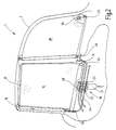
- FIG. 5 illustrates another embodiment of the double blind, both blind sheets 16 and 38 driven by a common drive device become. As far as in the embodiment of FIG. 5 already explained components are present, they are with the same Provide reference numerals. Another detailed one These components are not described. It applies accordingly the above.
- the difference to the embodiment according to the figure 1 consists in the manner in which the roller blind 38 in Sense of unwinding is driven.
- a gear 56 is used instead of the thrust link 48, which moves over the common drive motor 19 .
- the gear 56 comprises a threaded spindle 57 on which a spindle nut 58 is running.
- the spindle nut carries the arm 43, which in the is connected to the roller blind 38 in the same way as in Embodiment in Figure 1
- the threaded spindle 57 is non-rotatable with the winding shaft 14 coupled and runs parallel below the bottom edge of the window 7. If the installation conditions permit, the threaded spindle 57 can be rigid with the winding shaft 14 be coupled. If this is not possible, you can choose between the threaded spindle 57 and the winding shaft 14 also Universal joint can be inserted. In the latter case it is to mount the threaded spindle 57 rotatably at both ends. The bearing of the threaded spindle is sufficient for the rigid connection 57 at the free end.
- the gear ratio of the screw spindle 57 is again chosen so that both roller blinds 16 and 38 simultaneously reach their clamped end position according to FIG. 2.
- the double roller blind according to FIG. 5 is evident again with a common drive device for both Blinds 16 and 38 provided. Both roller blinds 16 and 38 are driven by the drive device, such that used to drive them, parts of the drive device that set both roller blinds in motion.
- the common drive device for the two roller blinds is not on the coupling of the electric drive confined to the free end of the roller blind.
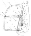
- Figure 6 shows an embodiment, at which the winding shafts via a common gear motor are driven.
- the geared motor 61 has an output shaft 62 which is rotatably coupled to the winding shaft 14. So that can the spring motor 15 is eliminated.
- the gear motor 61 is in the embodiment shown arranged at the end of the Winding shaft 35 lies.
- the end of the gear motor 61 opposite Winding shaft 14 carries a shaft journal 63 on which a Bevel gear 64 is seated.
- the bevel gear 64 meshes with one Bevel gear 65, which in turn is rotationally fixed to the winding shaft 35 communicates.
- the guide carriage already explained 42 which is only indicated in FIG. 6, is with a linear tension member in the form of a Cord or rope 66 connected.
- the rope 66 runs around one in the door 1 stationary pulley 67 around, which is beyond of the stroke of the guide carriage 65.
- the other End of the tension member 66 is a tension spring 68, the is anchored in the door 1, acted upon.
- a similar arrangement of rope spring and pulley can be used to pull rod 18 at both ends to bias in the direction away from the winding shaft 14.
- the geared motor 61 is used to extend the two Blinds 16 and 38 turned on with a Direction of rotation, in the sense of unwinding the blind sheet 16 from the winding shaft 14. This rotary movement is simultaneous via the bevel gear from the two bevel gears 64 and 65 transferred to the winding shaft 35. Because the free end the roller blind 38 via the tension member 66 and the tension spring 68 is biased, the guide carriage 42 to the Move the rear edge 8 of the window section 6.
- the pull rod 18 is at both ends, as mentioned, by similar traction means and tension springs that the traction means 66 and the mainspring. 68 biased accordingly.
- the traction means 66 and the mainspring. 68 biased accordingly.
- the position of the geared motor 61 is only in FIG. 6 indicated schematically. It is understood that at corresponding installation conditions of the geared motor 61 also between the winding shaft 14 and the bevel gear 64 can be inserted. It is also conceivable for the output shaft the gear motor 61 via a further bevel gear, for example, to engage in the bevel gear 64.
- a double roller blind for a split window of a motor vehicle provides two separate winding shafts, the one below any angles to each other are stored on the window.
- the roller blinds which are assigned to the respective winding shaft, inevitably moved at least in one direction.
- the electric motor with the free edges of the blinds be coupled or directly to the winding shafts.
Priority Applications (1)
| Application Number | Priority Date | Filing Date | Title |
|---|---|---|---|
| EP05007719A EP1550570B1 (fr) | 2001-10-24 | 2002-10-09 | Store à enrouler divisé pour une fenêtre de véhicule |
Applications Claiming Priority (2)
| Application Number | Priority Date | Filing Date | Title |
|---|---|---|---|
| DE10151872 | 2001-10-24 | ||
| DE10151872A DE10151872B4 (de) | 2001-10-24 | 2001-10-24 | Geteiltes Fensterrollo für Kraftfahrzeuge |
Related Child Applications (2)
| Application Number | Title | Priority Date | Filing Date |
|---|---|---|---|
| EP05007719A Division EP1550570B1 (fr) | 2001-10-24 | 2002-10-09 | Store à enrouler divisé pour une fenêtre de véhicule |
| EP05007719.7 Division-Into | 2005-04-08 |
Publications (2)
| Publication Number | Publication Date |
|---|---|
| EP1306251A1 true EP1306251A1 (fr) | 2003-05-02 |
| EP1306251B1 EP1306251B1 (fr) | 2005-11-23 |
Family
ID=7703187
Family Applications (2)
| Application Number | Title | Priority Date | Filing Date |
|---|---|---|---|
| EP02022610A Revoked EP1306251B1 (fr) | 2001-10-24 | 2002-10-09 | Store à enrouler divisé pour une fenêtre de véhicule |
| EP05007719A Expired - Fee Related EP1550570B1 (fr) | 2001-10-24 | 2002-10-09 | Store à enrouler divisé pour une fenêtre de véhicule |
Family Applications After (1)
| Application Number | Title | Priority Date | Filing Date |
|---|---|---|---|
| EP05007719A Expired - Fee Related EP1550570B1 (fr) | 2001-10-24 | 2002-10-09 | Store à enrouler divisé pour une fenêtre de véhicule |
Country Status (5)
| Country | Link |
|---|---|
| US (1) | US6910518B2 (fr) |
| EP (2) | EP1306251B1 (fr) |
| JP (2) | JP2003182358A (fr) |
| KR (1) | KR100876847B1 (fr) |
| DE (3) | DE10151872B4 (fr) |
Cited By (9)
| Publication number | Priority date | Publication date | Assignee | Title |
|---|---|---|---|---|
| DE10334721A1 (de) * | 2003-07-30 | 2005-02-24 | Bayerische Motoren Werke Aktiengesellschaft | Sonnenschutzeinrichtung |
| EP1533158A2 (fr) | 2003-11-19 | 2005-05-25 | BOS GmbH & Co. KG | Store à enrouleur pour vitres latérales |
| WO2007006883A1 (fr) * | 2005-07-08 | 2007-01-18 | Peugeot Citroen Automobiles S.A. | Pare-soleil motorise |
| EP1619057A3 (fr) * | 2004-07-24 | 2007-05-02 | BOS GmbH & Co. KG | Agencement de store pare-soleil pour vitre latérale |
| EP1964700A1 (fr) | 2007-02-28 | 2008-09-03 | HS Products Engineering GmbH | Store de fenêtre de véhicule |
| DE102007054694A1 (de) * | 2007-11-14 | 2009-05-20 | Bos Gmbh & Co. Kg | Rolloanordnung mit verminderter Reibung in den Antriebsgabeln |
| CN102712238A (zh) * | 2009-12-28 | 2012-10-03 | 芦森工业株式会社 | 车辆用窗户遮帘装置 |
| EP2581245A4 (fr) * | 2010-06-11 | 2015-07-15 | Ashimori Ind Co Ltd | Dispositif d'écran de glace de portière de véhicule |
| WO2016207189A1 (fr) * | 2015-06-22 | 2016-12-29 | Bos Gmbh & Co. Kg | Dispositif d'ombrage destiné à un système de vitre latérale en deux parties d'un véhicule automobile |
Families Citing this family (50)
| Publication number | Priority date | Publication date | Assignee | Title |
|---|---|---|---|---|
| DE10331514A1 (de) * | 2003-07-11 | 2005-02-03 | Arvinmeritor Gmbh | Sonnenschutzbaugruppe für ein Fahrzeugdach |
| DE10334695A1 (de) * | 2003-07-25 | 2005-02-10 | Brose Fahrzeugteile Gmbh & Co. Kg | Rollo-Anordnung für ein Fenster eines Kraftfahrzeugs |
| US7314079B2 (en) * | 2003-09-09 | 2008-01-01 | Asmo Co., Ltd. | Sunshade system having blind sheet |
| DE102004020335A1 (de) * | 2004-04-26 | 2005-11-17 | Webasto Ag | Rollosystem für ein Fahrzeugdach |
| DE102004020336C5 (de) * | 2004-04-26 | 2008-09-18 | Webasto Ag | Fahrzeudach mit einer Rolloanordnung |
| DE102004030262B3 (de) * | 2004-06-23 | 2006-04-27 | Bos Gmbh & Co. Kg | Rollo mit konischer Wickelwelle |
| DE102004049167A1 (de) * | 2004-10-08 | 2006-04-20 | Hs Products Engineering Gmbh | Fensterrollo für ein Fahrzeugfenster |
| DE102005023967B4 (de) * | 2005-05-20 | 2007-04-19 | Bos Gmbh & Co. Kg | Fensterrollo mit längsverstellbarer Wickelwelle |
| JP4560442B2 (ja) * | 2005-05-23 | 2010-10-13 | トヨタ紡織株式会社 | サンシェード開閉装置 |
| DE102005030707A1 (de) * | 2005-06-29 | 2007-01-04 | Bos Gmbh & Co. Kg | Fensterrollo für Kraftfahrzeuge mit formschlüssigem Anschlag auf dem Betätigungsglied |
| US20070068638A1 (en) * | 2005-09-28 | 2007-03-29 | Puskarz Mitchell M | Anti-wind buffeting device for an automobile |
| DE102005057248B4 (de) * | 2005-11-29 | 2010-09-16 | Johnson Controls Interiors Gmbh & Co. Kg | Flächenbündig um die Brüstung einer Seitenverkleidung eines Kraftfahrzeuges integriertes Sonnenschutzrollo |
| DE102006019455A1 (de) * | 2006-04-26 | 2007-10-31 | Hs Products Engineering Gmbh | Fensterrollo, welches an der Innenseite eines Kraftfahrzeugfensters anzuordnen ist |
| US7401840B2 (en) * | 2006-05-09 | 2008-07-22 | Gm Global Technology Operations, Inc. | Window shade |
| JP4917356B2 (ja) * | 2006-06-01 | 2012-04-18 | 株式会社ハイレックスコーポレーション | サンシェード操作装置 |
| JP4247753B2 (ja) * | 2006-08-10 | 2009-04-02 | トヨタ紡織株式会社 | サンシェード装置 |
| JP4247751B2 (ja) * | 2006-08-10 | 2009-04-02 | トヨタ紡織株式会社 | サンシェード装置 |
| JP4247752B2 (ja) * | 2006-08-10 | 2009-04-02 | トヨタ紡織株式会社 | サンシェード装置 |
| US7493933B2 (en) * | 2006-08-15 | 2009-02-24 | Li Xinian | Retractable window shade |
| DE102006040317A1 (de) * | 2006-08-29 | 2008-03-20 | Bos Gmbh & Co. Kg | Seitenfensterrollo |
| DE102006047348A1 (de) | 2006-09-29 | 2008-04-03 | Brose Fahrzeugteile Gmbh & Co. Kommanditgesellschaft, Coburg | Antriebsvorrichtung zum Bewegen eines Abdeckelementes, Türbaugruppe und Verfahren zur Montage der Antriebsvorrichtung |
| JP4748032B2 (ja) * | 2006-11-07 | 2011-08-17 | トヨタ紡織株式会社 | サンバイザ |
| KR100854074B1 (ko) * | 2007-02-28 | 2008-08-25 | 주식회사 광진엔지니어링 | 차량용 도어개방 장치 |
| DE102007011270A1 (de) * | 2007-03-08 | 2008-07-03 | Audi Ag | Sonnenschutzsystem für Kraftfahrzeugseitenfenster |
| DE102007012281A1 (de) * | 2007-03-09 | 2008-09-11 | Bos Gmbh & Co. Kg | Automatisch betätigbares Seitenfensterrollo |
| DE102007012259A1 (de) * | 2007-03-12 | 2008-09-18 | Bos Gmbh & Co. Kg | Sonnenschutzrollo für Kraftfahrzeuge |
| DE102007016154A1 (de) * | 2007-03-21 | 2008-09-25 | Bos Gmbh & Co. Kg | Seitenfensterrollo mit anscharniertem Zugstab und rechteckigem Tragstab |
| DE202007005160U1 (de) * | 2007-04-03 | 2008-08-14 | Brose Fahrzeugteile Gmbh & Co. Kommanditgesellschaft, Hallstadt | Fahrzeugrollo |
| DE102007028585A1 (de) * | 2007-06-19 | 2008-12-24 | Bos Gmbh & Co. Kg | Elektrisches Seitenfensterrollo |
| DE102008011505B4 (de) * | 2008-02-22 | 2011-03-03 | Bos Gmbh & Co. Kg | Rollosystem für ein Fahrzeug |
| KR100969662B1 (ko) * | 2008-04-22 | 2010-07-14 | 김도언 | 내용물 배출구 일체형 손잡이가 구비된 포장팩 및 포장팩용손잡이 |
| US7673925B2 (en) * | 2008-07-11 | 2010-03-09 | Macauto Industrial Co., Ltd. | Drive motor assembly for a vehicle sunshade assembly |
| KR101080760B1 (ko) * | 2009-08-26 | 2011-11-07 | 평화정공 주식회사 | 차량용 차양장치 |
| JP5427732B2 (ja) * | 2010-08-26 | 2014-02-26 | 本田技研工業株式会社 | 車両用ブラインド装置 |
| JP5719585B2 (ja) * | 2010-12-27 | 2015-05-20 | 芦森工業株式会社 | シェード装置 |
| CN103269887B (zh) * | 2010-12-28 | 2015-08-26 | 芦森工业株式会社 | 车辆用窗遮蔽装置 |
| DE102011007004B8 (de) * | 2011-04-07 | 2013-01-10 | Bos Gmbh & Co. Kg | Rollobaueinheit für ein Kraftfahrzeug |
| JP5634935B2 (ja) * | 2011-04-07 | 2014-12-03 | 芦森工業株式会社 | シェード装置 |
| DE102011076892A1 (de) * | 2011-06-01 | 2012-12-06 | Bos Gmbh & Co. Kg | Beschattungssystem und Rolloeinheit hierfür |
| JP5758782B2 (ja) * | 2011-11-24 | 2015-08-05 | 芦森工業株式会社 | ウインドウシェード装置 |
| DE102013110650A1 (de) | 2013-09-26 | 2015-03-26 | Dr. Ing. H.C. F. Porsche Aktiengesellschaft | Anordnung für ein Rollo |
| JP6629049B2 (ja) * | 2015-11-18 | 2020-01-15 | 芦森工業株式会社 | 車両用シェード装置 |
| CN105480059B (zh) * | 2015-12-14 | 2017-09-15 | 福耀玻璃工业集团股份有限公司 | 一种车窗用卷帘系统 |
| DE102016206301B4 (de) * | 2016-04-14 | 2017-11-30 | Bos Gmbh & Co. Kg | Beschattungssystem für ein Kraftfahrzeug |
| JP6642269B2 (ja) * | 2016-05-23 | 2020-02-05 | トヨタ紡織株式会社 | 乗物用窓装置 |
| US10661638B2 (en) * | 2016-06-24 | 2020-05-26 | Macauto Industrial Co., Ltd | Shade arrangement for vehicle |
| DE102016111658B4 (de) * | 2016-06-24 | 2022-07-21 | Macauto Industrial Co., Ltd. | Verschattungsvorrichtung für ein Fahrzeug |
| US11472269B1 (en) * | 2017-08-29 | 2022-10-18 | Larhonda Quinn | Vehicle window screen |
| KR20220006886A (ko) * | 2020-07-09 | 2022-01-18 | 현대자동차주식회사 | 차량용 전동커튼 장치 |
| US20230136980A1 (en) * | 2020-07-21 | 2023-05-04 | Dawn Tech Ltd | An Electric Spiraling Piston and Systems Devices Apparatuses and Methods Utilizing Same |
Citations (3)
| Publication number | Priority date | Publication date | Assignee | Title |
|---|---|---|---|---|
| FR2786809A1 (fr) * | 1998-12-03 | 2000-06-09 | Webasto Systemes Carrosserie | Dispositif d'entrainement d'au moins un rideau d'occultation du panneau coulissant d'un toit ouvrant pour automobile |
| EP1129871A1 (fr) * | 2000-03-03 | 2001-09-05 | Schwab Technik GmbH | Dispositif de store de fenêtre pour fenêtres de véhicules |
| EP1188591A1 (fr) * | 2000-09-19 | 2002-03-20 | BOS GmbH & Co. KG | Store à rouleau de fenêtre pour vitres de véhicule courbées ou non rectangulaires |
Family Cites Families (19)
| Publication number | Priority date | Publication date | Assignee | Title |
|---|---|---|---|---|
| DE1005970B (de) | 1953-08-10 | 1957-04-11 | Norwich Pharma Co | Verfahren zur Herstellung neuer Hydrazone der 5-Nitrofuran-Reihe |
| US3050075A (en) * | 1960-07-05 | 1962-08-21 | Kaplan Rose | Retractable vehicle covering device |
| US4874026A (en) * | 1988-04-04 | 1989-10-17 | Dayer Worrall | Vehicle window screen assembly |
| FR2646203B1 (fr) * | 1989-04-19 | 1991-07-26 | Farnier & Penin | Store a enrouleur motorise |
| JP2822336B2 (ja) * | 1990-09-28 | 1998-11-11 | 日本発条株式会社 | シート状物巻取装置 |
| US6047762A (en) * | 1998-03-20 | 2000-04-11 | Prince Corporation | Shade control for a vehicle window |
| DE29921859U1 (de) * | 1999-12-13 | 2000-07-27 | Hs Products Ag Systemtechnik U | Seitenfensterrollo |
| DE29921860U1 (de) * | 1999-12-13 | 2000-07-13 | Hs Products Ag Systemtechnik U | Fensterrollo für ein Dreiecksfenster eines Kraftfahrzeugs |
| DE10005970A1 (de) * | 2000-02-09 | 2001-08-23 | Bos Gmbh | Seitenfensterrollo |
| DE10005951A1 (de) * | 2000-02-09 | 2001-08-16 | Bos Gmbh | Heckfensterrollo |
| DE10020212B4 (de) * | 2000-04-25 | 2004-02-19 | Bos Gmbh & Co. Kg | Seitenfensterrollo mit Schlitzabdeckung |
| DE10057763C2 (de) * | 2000-11-22 | 2002-10-24 | Bos Gmbh | Doppelrollo mit vereinfachtem Antrieb |
| DE10057764B4 (de) * | 2000-11-22 | 2005-06-09 | Bos Gmbh & Co. Kg | Fensterrollo mit variabler Abschattungswirkung |
| DE10057759A1 (de) * | 2000-11-22 | 2002-06-06 | Bos Gmbh | Fensterscheibe mit daran befestigtem Fensterrollo |
| DE10057760B4 (de) * | 2000-11-22 | 2004-08-12 | Bos Gmbh & Co. Kg | Fensterrollo mit Zentriereinrichtung für den Zugstab |
| DE10057762A1 (de) * | 2000-11-22 | 2002-06-06 | Bos Gmbh | Fensterrollo mit Ausgleich gegen Verzug |
| DE10101491C1 (de) * | 2001-01-12 | 2002-05-08 | Cts Fahrzeug Dachsysteme Gmbh | Rollo für ein durchsichtiges Dachteil in einem Fahrzeugdach |
| KR100425005B1 (ko) * | 2001-10-10 | 2004-03-30 | 코리아에프티 주식회사 | 자동차의 차양장치 |
| DE10228027B4 (de) * | 2002-06-24 | 2006-04-13 | Bos Gmbh & Co. Kg | Fensterrollo mit klapperfreier Führung |
-
2001
- 2001-10-24 DE DE10151872A patent/DE10151872B4/de not_active Expired - Fee Related
-
2002
- 2002-10-09 DE DE50213997T patent/DE50213997D1/de not_active Expired - Lifetime
- 2002-10-09 EP EP02022610A patent/EP1306251B1/fr not_active Revoked
- 2002-10-09 DE DE50205016T patent/DE50205016D1/de not_active Revoked
- 2002-10-09 EP EP05007719A patent/EP1550570B1/fr not_active Expired - Fee Related
- 2002-10-23 KR KR1020020064779A patent/KR100876847B1/ko not_active IP Right Cessation
- 2002-10-23 US US10/278,628 patent/US6910518B2/en not_active Expired - Fee Related
- 2002-10-24 JP JP2002310110A patent/JP2003182358A/ja not_active Ceased
-
2008
- 2008-12-19 JP JP2008324287A patent/JP2009073491A/ja not_active Withdrawn
Patent Citations (3)
| Publication number | Priority date | Publication date | Assignee | Title |
|---|---|---|---|---|
| FR2786809A1 (fr) * | 1998-12-03 | 2000-06-09 | Webasto Systemes Carrosserie | Dispositif d'entrainement d'au moins un rideau d'occultation du panneau coulissant d'un toit ouvrant pour automobile |
| EP1129871A1 (fr) * | 2000-03-03 | 2001-09-05 | Schwab Technik GmbH | Dispositif de store de fenêtre pour fenêtres de véhicules |
| EP1188591A1 (fr) * | 2000-09-19 | 2002-03-20 | BOS GmbH & Co. KG | Store à rouleau de fenêtre pour vitres de véhicule courbées ou non rectangulaires |
Cited By (15)
| Publication number | Priority date | Publication date | Assignee | Title |
|---|---|---|---|---|
| DE10334721A1 (de) * | 2003-07-30 | 2005-02-24 | Bayerische Motoren Werke Aktiengesellschaft | Sonnenschutzeinrichtung |
| EP1533158A3 (fr) * | 2003-11-19 | 2007-09-12 | BOS GmbH & Co. KG | Store à enrouleur pour vitres latérales |
| EP1533158A2 (fr) | 2003-11-19 | 2005-05-25 | BOS GmbH & Co. KG | Store à enrouleur pour vitres latérales |
| US7347246B2 (en) | 2003-11-19 | 2008-03-25 | Bos Gmbh & Co. Kg | Side window shade with contour part |
| CN1724844B (zh) * | 2004-07-24 | 2011-09-07 | 博斯股份有限两合公司 | 侧窗卷帘装置 |
| EP1619057A3 (fr) * | 2004-07-24 | 2007-05-02 | BOS GmbH & Co. KG | Agencement de store pare-soleil pour vitre latérale |
| WO2007006883A1 (fr) * | 2005-07-08 | 2007-01-18 | Peugeot Citroen Automobiles S.A. | Pare-soleil motorise |
| EP1964700A1 (fr) | 2007-02-28 | 2008-09-03 | HS Products Engineering GmbH | Store de fenêtre de véhicule |
| DE102007054694A1 (de) * | 2007-11-14 | 2009-05-20 | Bos Gmbh & Co. Kg | Rolloanordnung mit verminderter Reibung in den Antriebsgabeln |
| EP2060421A1 (fr) * | 2007-11-14 | 2009-05-20 | BOS GmbH & Co. KG | Agencement de store doté d'un entraînement à friction réduite |
| CN102712238A (zh) * | 2009-12-28 | 2012-10-03 | 芦森工业株式会社 | 车辆用窗户遮帘装置 |
| EP2520450A4 (fr) * | 2009-12-28 | 2015-09-09 | Ashimori Ind Co Ltd | Dispositif de store de fenêtre pour véhicule |
| CN102712238B (zh) * | 2009-12-28 | 2016-01-20 | 芦森工业株式会社 | 车辆用窗户遮帘装置 |
| EP2581245A4 (fr) * | 2010-06-11 | 2015-07-15 | Ashimori Ind Co Ltd | Dispositif d'écran de glace de portière de véhicule |
| WO2016207189A1 (fr) * | 2015-06-22 | 2016-12-29 | Bos Gmbh & Co. Kg | Dispositif d'ombrage destiné à un système de vitre latérale en deux parties d'un véhicule automobile |
Also Published As
| Publication number | Publication date |
|---|---|
| KR100876847B1 (ko) | 2008-12-31 |
| DE50213997D1 (de) | 2009-12-24 |
| EP1306251B1 (fr) | 2005-11-23 |
| EP1550570A3 (fr) | 2005-08-03 |
| EP1550570A2 (fr) | 2005-07-06 |
| DE10151872B4 (de) | 2007-10-04 |
| EP1550570B1 (fr) | 2009-11-11 |
| US20030094249A1 (en) | 2003-05-22 |
| US6910518B2 (en) | 2005-06-28 |
| KR20030033985A (ko) | 2003-05-01 |
| JP2009073491A (ja) | 2009-04-09 |
| DE10151872A1 (de) | 2003-05-15 |
| DE50205016D1 (de) | 2005-12-29 |
| JP2003182358A (ja) | 2003-07-03 |
Similar Documents
| Publication | Publication Date | Title |
|---|---|---|
| EP1306251A1 (fr) | Store à enrouler divisé pour une fenêtre de véhicule | |
| EP1905630B1 (fr) | Store de fenêtre actionné manuellement | |
| EP1211109B1 (fr) | Store à enrouler avec dispositif de centrage pour la tige de tension | |
| EP1182066B1 (fr) | Véhicule avec store à enrouleur dans le toit | |
| EP1468853B1 (fr) | Store à enrouleur pour vitres latérales | |
| EP1970235B1 (fr) | Store de fenêtre latérale doté d'un entraînement à corde | |
| EP2060421B1 (fr) | Agencement de store doté d'un entraînement à friction réduite | |
| EP1209013A2 (fr) | Vitre avec store à enrouleur attaché | |
| EP1418073A1 (fr) | Store à enrouler avec couvercle sur la fente extracte | |
| DE10057764A1 (de) | Fensterrollo mit variabler Abschattungswirkung | |
| DE102006046069A1 (de) | Fensterrollo mit reibungsmindertem Antrieb | |
| EP1747923A2 (fr) | Store à enrouler de fenêtre avec des pousées non-profilées | |
| DE102004020531B3 (de) | Fensterrollo mit justierbarer Zentrierung des Zugstabs | |
| DE102006028353A1 (de) | Fensterrollo für ein Fahrzeugfenster | |
| EP3478521B1 (fr) | Dispositif d'ombrage pour une vitre de véhicule automobile | |
| DE102017218895B4 (de) | Schutzvorrichtung für einen Innenraum eines Kraftfahrzeugs | |
| WO2006063565A1 (fr) | Store pour vitre de vehicule | |
| DE102021204275A1 (de) | Schutzvorrichtung für eine Fensteröffnung eines Kraftfahrzeugs | |
| DE202006017838U1 (de) | Fensterrollo mit reibungsgemindertem Antrieb | |
| EP1972477B1 (fr) | Store de fenêtre latérale doté d'une barre de traction à charnière et d'une barre de support carrée | |
| DE202006017842U1 (de) | Rollo mit hinterschneidungsfreier Führungsschiene | |
| DE10316785B4 (de) | Rollovorrichtung | |
| DE202007008178U1 (de) | Seitenfensterrollo | |
| DE19503439C1 (de) | Gegenzugmarkise | |
| DE10150693A1 (de) | Gegenzugmarkise mit Führungsrollen mit Rillen |
Legal Events
| Date | Code | Title | Description |
|---|---|---|---|
| PUAI | Public reference made under article 153(3) epc to a published international application that has entered the european phase |
Free format text: ORIGINAL CODE: 0009012 |
|
| AK | Designated contracting states |
Designated state(s): AT BE BG CH CY CZ DE DK EE ES FI FR GB GR IE IT LI LU MC NL PT SE SK TR |
|
| AX | Request for extension of the european patent |
Extension state: AL LT LV MK RO SI |
|
| 17P | Request for examination filed |
Effective date: 20030723 |
|
| 17Q | First examination report despatched |
Effective date: 20030923 |
|
| AKX | Designation fees paid |
Designated state(s): DE FR GB IT |
|
| GRAP | Despatch of communication of intention to grant a patent |
Free format text: ORIGINAL CODE: EPIDOSNIGR1 |
|
| GRAS | Grant fee paid |
Free format text: ORIGINAL CODE: EPIDOSNIGR3 |
|
| GRAA | (expected) grant |
Free format text: ORIGINAL CODE: 0009210 |
|
| AK | Designated contracting states |
Kind code of ref document: B1 Designated state(s): DE FR GB IT |
|
| PG25 | Lapsed in a contracting state [announced via postgrant information from national office to epo] |
Ref country code: IT Free format text: LAPSE BECAUSE OF FAILURE TO SUBMIT A TRANSLATION OF THE DESCRIPTION OR TO PAY THE FEE WITHIN THE PRESCRIBED TIME-LIMIT;WARNING: LAPSES OF ITALIAN PATENTS WITH EFFECTIVE DATE BEFORE 2007 MAY HAVE OCCURRED AT ANY TIME BEFORE 2007. THE CORRECT EFFECTIVE DATE MAY BE DIFFERENT FROM THE ONE RECORDED. Effective date: 20051123 |
|
| REG | Reference to a national code |
Ref country code: GB Ref legal event code: FG4D Free format text: NOT ENGLISH |
|
| REF | Corresponds to: |
Ref document number: 50205016 Country of ref document: DE Date of ref document: 20051229 Kind code of ref document: P |
|
| GBT | Gb: translation of ep patent filed (gb section 77(6)(a)/1977) |
Effective date: 20060107 |
|
| ET | Fr: translation filed | ||
| PLBI | Opposition filed |
Free format text: ORIGINAL CODE: 0009260 |
|
| PLAX | Notice of opposition and request to file observation + time limit sent |
Free format text: ORIGINAL CODE: EPIDOSNOBS2 |
|
| 26 | Opposition filed |
Opponent name: LISA DRAEXLMAIER SYSTEMTECHNIK GMBH Effective date: 20060823 |
|
| PLAB | Opposition data, opponent's data or that of the opponent's representative modified |
Free format text: ORIGINAL CODE: 0009299OPPO |
|
| R26 | Opposition filed (corrected) |
Opponent name: LISA DRAEXLMAIER GMBH Effective date: 20060823 |
|
| PLAF | Information modified related to communication of a notice of opposition and request to file observations + time limit |
Free format text: ORIGINAL CODE: EPIDOSCOBS2 |
|
| PLBB | Reply of patent proprietor to notice(s) of opposition received |
Free format text: ORIGINAL CODE: EPIDOSNOBS3 |
|
| RDAF | Communication despatched that patent is revoked |
Free format text: ORIGINAL CODE: EPIDOSNREV1 |
|
| PGFP | Annual fee paid to national office [announced via postgrant information from national office to epo] |
Ref country code: DE Payment date: 20081031 Year of fee payment: 7 |
|
| RDAG | Patent revoked |
Free format text: ORIGINAL CODE: 0009271 |
|
| STAA | Information on the status of an ep patent application or granted ep patent |
Free format text: STATUS: PATENT REVOKED |
|
| 27W | Patent revoked |
Effective date: 20081106 |
|
| GBPR | Gb: patent revoked under art. 102 of the ep convention designating the uk as contracting state |
Effective date: 20081106 |
|
| PGFP | Annual fee paid to national office [announced via postgrant information from national office to epo] |
Ref country code: IT Payment date: 20081022 Year of fee payment: 7 |
|
| PGFP | Annual fee paid to national office [announced via postgrant information from national office to epo] |
Ref country code: FR Payment date: 20081014 Year of fee payment: 7 |
|
| PGFP | Annual fee paid to national office [announced via postgrant information from national office to epo] |
Ref country code: GB Payment date: 20081021 Year of fee payment: 7 |