EP1300587A1 - Antriebssystem - Google Patents
Antriebssystem Download PDFInfo
- Publication number
- EP1300587A1 EP1300587A1 EP01949946A EP01949946A EP1300587A1 EP 1300587 A1 EP1300587 A1 EP 1300587A1 EP 01949946 A EP01949946 A EP 01949946A EP 01949946 A EP01949946 A EP 01949946A EP 1300587 A1 EP1300587 A1 EP 1300587A1
- Authority
- EP
- European Patent Office
- Prior art keywords
- torque
- engine
- electric motor
- control unit
- control
- Prior art date
- Legal status (The legal status is an assumption and is not a legal conclusion. Google has not performed a legal analysis and makes no representation as to the accuracy of the status listed.)
- Granted
Links
Images


Classifications
-
- F—MECHANICAL ENGINEERING; LIGHTING; HEATING; WEAPONS; BLASTING
- F02—COMBUSTION ENGINES; HOT-GAS OR COMBUSTION-PRODUCT ENGINE PLANTS
- F02N—STARTING OF COMBUSTION ENGINES; STARTING AIDS FOR SUCH ENGINES, NOT OTHERWISE PROVIDED FOR
- F02N11/00—Starting of engines by means of electric motors
- F02N11/08—Circuits or control means specially adapted for starting of engines
-
- B—PERFORMING OPERATIONS; TRANSPORTING
- B60—VEHICLES IN GENERAL
- B60W—CONJOINT CONTROL OF VEHICLE SUB-UNITS OF DIFFERENT TYPE OR DIFFERENT FUNCTION; CONTROL SYSTEMS SPECIALLY ADAPTED FOR HYBRID VEHICLES; ROAD VEHICLE DRIVE CONTROL SYSTEMS FOR PURPOSES NOT RELATED TO THE CONTROL OF A PARTICULAR SUB-UNIT
- B60W20/00—Control systems specially adapted for hybrid vehicles
-
- B—PERFORMING OPERATIONS; TRANSPORTING
- B60—VEHICLES IN GENERAL
- B60K—ARRANGEMENT OR MOUNTING OF PROPULSION UNITS OR OF TRANSMISSIONS IN VEHICLES; ARRANGEMENT OR MOUNTING OF PLURAL DIVERSE PRIME-MOVERS IN VEHICLES; AUXILIARY DRIVES FOR VEHICLES; INSTRUMENTATION OR DASHBOARDS FOR VEHICLES; ARRANGEMENTS IN CONNECTION WITH COOLING, AIR INTAKE, GAS EXHAUST OR FUEL SUPPLY OF PROPULSION UNITS IN VEHICLES
- B60K6/00—Arrangement or mounting of plural diverse prime-movers for mutual or common propulsion, e.g. hybrid propulsion systems comprising electric motors and internal combustion engines ; Control systems therefor, i.e. systems controlling two or more prime movers, or controlling one of these prime movers and any of the transmission, drive or drive units Informative references: mechanical gearings with secondary electric drive F16H3/72; arrangements for handling mechanical energy structurally associated with the dynamo-electric machine H02K7/00; machines comprising structurally interrelated motor and generator parts H02K51/00; dynamo-electric machines not otherwise provided for in H02K see H02K99/00
- B60K6/20—Arrangement or mounting of plural diverse prime-movers for mutual or common propulsion, e.g. hybrid propulsion systems comprising electric motors and internal combustion engines ; Control systems therefor, i.e. systems controlling two or more prime movers, or controlling one of these prime movers and any of the transmission, drive or drive units Informative references: mechanical gearings with secondary electric drive F16H3/72; arrangements for handling mechanical energy structurally associated with the dynamo-electric machine H02K7/00; machines comprising structurally interrelated motor and generator parts H02K51/00; dynamo-electric machines not otherwise provided for in H02K see H02K99/00 the prime-movers consisting of electric motors and internal combustion engines, e.g. HEVs
- B60K6/22—Arrangement or mounting of plural diverse prime-movers for mutual or common propulsion, e.g. hybrid propulsion systems comprising electric motors and internal combustion engines ; Control systems therefor, i.e. systems controlling two or more prime movers, or controlling one of these prime movers and any of the transmission, drive or drive units Informative references: mechanical gearings with secondary electric drive F16H3/72; arrangements for handling mechanical energy structurally associated with the dynamo-electric machine H02K7/00; machines comprising structurally interrelated motor and generator parts H02K51/00; dynamo-electric machines not otherwise provided for in H02K see H02K99/00 the prime-movers consisting of electric motors and internal combustion engines, e.g. HEVs characterised by apparatus, components or means specially adapted for HEVs
- B60K6/38—Arrangement or mounting of plural diverse prime-movers for mutual or common propulsion, e.g. hybrid propulsion systems comprising electric motors and internal combustion engines ; Control systems therefor, i.e. systems controlling two or more prime movers, or controlling one of these prime movers and any of the transmission, drive or drive units Informative references: mechanical gearings with secondary electric drive F16H3/72; arrangements for handling mechanical energy structurally associated with the dynamo-electric machine H02K7/00; machines comprising structurally interrelated motor and generator parts H02K51/00; dynamo-electric machines not otherwise provided for in H02K see H02K99/00 the prime-movers consisting of electric motors and internal combustion engines, e.g. HEVs characterised by apparatus, components or means specially adapted for HEVs characterised by the driveline clutches
- B60K6/383—One-way clutches or freewheel devices
-
- B—PERFORMING OPERATIONS; TRANSPORTING
- B60—VEHICLES IN GENERAL
- B60K—ARRANGEMENT OR MOUNTING OF PROPULSION UNITS OR OF TRANSMISSIONS IN VEHICLES; ARRANGEMENT OR MOUNTING OF PLURAL DIVERSE PRIME-MOVERS IN VEHICLES; AUXILIARY DRIVES FOR VEHICLES; INSTRUMENTATION OR DASHBOARDS FOR VEHICLES; ARRANGEMENTS IN CONNECTION WITH COOLING, AIR INTAKE, GAS EXHAUST OR FUEL SUPPLY OF PROPULSION UNITS IN VEHICLES
- B60K6/00—Arrangement or mounting of plural diverse prime-movers for mutual or common propulsion, e.g. hybrid propulsion systems comprising electric motors and internal combustion engines ; Control systems therefor, i.e. systems controlling two or more prime movers, or controlling one of these prime movers and any of the transmission, drive or drive units Informative references: mechanical gearings with secondary electric drive F16H3/72; arrangements for handling mechanical energy structurally associated with the dynamo-electric machine H02K7/00; machines comprising structurally interrelated motor and generator parts H02K51/00; dynamo-electric machines not otherwise provided for in H02K see H02K99/00
- B60K6/20—Arrangement or mounting of plural diverse prime-movers for mutual or common propulsion, e.g. hybrid propulsion systems comprising electric motors and internal combustion engines ; Control systems therefor, i.e. systems controlling two or more prime movers, or controlling one of these prime movers and any of the transmission, drive or drive units Informative references: mechanical gearings with secondary electric drive F16H3/72; arrangements for handling mechanical energy structurally associated with the dynamo-electric machine H02K7/00; machines comprising structurally interrelated motor and generator parts H02K51/00; dynamo-electric machines not otherwise provided for in H02K see H02K99/00 the prime-movers consisting of electric motors and internal combustion engines, e.g. HEVs
- B60K6/42—Arrangement or mounting of plural diverse prime-movers for mutual or common propulsion, e.g. hybrid propulsion systems comprising electric motors and internal combustion engines ; Control systems therefor, i.e. systems controlling two or more prime movers, or controlling one of these prime movers and any of the transmission, drive or drive units Informative references: mechanical gearings with secondary electric drive F16H3/72; arrangements for handling mechanical energy structurally associated with the dynamo-electric machine H02K7/00; machines comprising structurally interrelated motor and generator parts H02K51/00; dynamo-electric machines not otherwise provided for in H02K see H02K99/00 the prime-movers consisting of electric motors and internal combustion engines, e.g. HEVs characterised by the architecture of the hybrid electric vehicle
- B60K6/44—Series-parallel type
- B60K6/445—Differential gearing distribution type
-
- B—PERFORMING OPERATIONS; TRANSPORTING
- B60—VEHICLES IN GENERAL
- B60K—ARRANGEMENT OR MOUNTING OF PROPULSION UNITS OR OF TRANSMISSIONS IN VEHICLES; ARRANGEMENT OR MOUNTING OF PLURAL DIVERSE PRIME-MOVERS IN VEHICLES; AUXILIARY DRIVES FOR VEHICLES; INSTRUMENTATION OR DASHBOARDS FOR VEHICLES; ARRANGEMENTS IN CONNECTION WITH COOLING, AIR INTAKE, GAS EXHAUST OR FUEL SUPPLY OF PROPULSION UNITS IN VEHICLES
- B60K6/00—Arrangement or mounting of plural diverse prime-movers for mutual or common propulsion, e.g. hybrid propulsion systems comprising electric motors and internal combustion engines ; Control systems therefor, i.e. systems controlling two or more prime movers, or controlling one of these prime movers and any of the transmission, drive or drive units Informative references: mechanical gearings with secondary electric drive F16H3/72; arrangements for handling mechanical energy structurally associated with the dynamo-electric machine H02K7/00; machines comprising structurally interrelated motor and generator parts H02K51/00; dynamo-electric machines not otherwise provided for in H02K see H02K99/00
- B60K6/20—Arrangement or mounting of plural diverse prime-movers for mutual or common propulsion, e.g. hybrid propulsion systems comprising electric motors and internal combustion engines ; Control systems therefor, i.e. systems controlling two or more prime movers, or controlling one of these prime movers and any of the transmission, drive or drive units Informative references: mechanical gearings with secondary electric drive F16H3/72; arrangements for handling mechanical energy structurally associated with the dynamo-electric machine H02K7/00; machines comprising structurally interrelated motor and generator parts H02K51/00; dynamo-electric machines not otherwise provided for in H02K see H02K99/00 the prime-movers consisting of electric motors and internal combustion engines, e.g. HEVs
- B60K6/42—Arrangement or mounting of plural diverse prime-movers for mutual or common propulsion, e.g. hybrid propulsion systems comprising electric motors and internal combustion engines ; Control systems therefor, i.e. systems controlling two or more prime movers, or controlling one of these prime movers and any of the transmission, drive or drive units Informative references: mechanical gearings with secondary electric drive F16H3/72; arrangements for handling mechanical energy structurally associated with the dynamo-electric machine H02K7/00; machines comprising structurally interrelated motor and generator parts H02K51/00; dynamo-electric machines not otherwise provided for in H02K see H02K99/00 the prime-movers consisting of electric motors and internal combustion engines, e.g. HEVs characterised by the architecture of the hybrid electric vehicle
- B60K6/46—Series type
-
- B—PERFORMING OPERATIONS; TRANSPORTING
- B60—VEHICLES IN GENERAL
- B60L—PROPULSION OF ELECTRICALLY-PROPELLED VEHICLES; SUPPLYING ELECTRIC POWER FOR AUXILIARY EQUIPMENT OF ELECTRICALLY-PROPELLED VEHICLES; ELECTRODYNAMIC BRAKE SYSTEMS FOR VEHICLES IN GENERAL; MAGNETIC SUSPENSION OR LEVITATION FOR VEHICLES; MONITORING OPERATING VARIABLES OF ELECTRICALLY-PROPELLED VEHICLES; ELECTRIC SAFETY DEVICES FOR ELECTRICALLY-PROPELLED VEHICLES
- B60L15/00—Methods, circuits, or devices for controlling the traction-motor speed of electrically-propelled vehicles
- B60L15/20—Methods, circuits, or devices for controlling the traction-motor speed of electrically-propelled vehicles for control of the vehicle or its driving motor to achieve a desired performance, e.g. speed, torque, programmed variation of speed
-
- B—PERFORMING OPERATIONS; TRANSPORTING
- B60—VEHICLES IN GENERAL
- B60L—PROPULSION OF ELECTRICALLY-PROPELLED VEHICLES; SUPPLYING ELECTRIC POWER FOR AUXILIARY EQUIPMENT OF ELECTRICALLY-PROPELLED VEHICLES; ELECTRODYNAMIC BRAKE SYSTEMS FOR VEHICLES IN GENERAL; MAGNETIC SUSPENSION OR LEVITATION FOR VEHICLES; MONITORING OPERATING VARIABLES OF ELECTRICALLY-PROPELLED VEHICLES; ELECTRIC SAFETY DEVICES FOR ELECTRICALLY-PROPELLED VEHICLES
- B60L50/00—Electric propulsion with power supplied within the vehicle
- B60L50/10—Electric propulsion with power supplied within the vehicle using propulsion power supplied by engine-driven generators, e.g. generators driven by combustion engines
- B60L50/16—Electric propulsion with power supplied within the vehicle using propulsion power supplied by engine-driven generators, e.g. generators driven by combustion engines with provision for separate direct mechanical propulsion
-
- B—PERFORMING OPERATIONS; TRANSPORTING
- B60—VEHICLES IN GENERAL
- B60L—PROPULSION OF ELECTRICALLY-PROPELLED VEHICLES; SUPPLYING ELECTRIC POWER FOR AUXILIARY EQUIPMENT OF ELECTRICALLY-PROPELLED VEHICLES; ELECTRODYNAMIC BRAKE SYSTEMS FOR VEHICLES IN GENERAL; MAGNETIC SUSPENSION OR LEVITATION FOR VEHICLES; MONITORING OPERATING VARIABLES OF ELECTRICALLY-PROPELLED VEHICLES; ELECTRIC SAFETY DEVICES FOR ELECTRICALLY-PROPELLED VEHICLES
- B60L50/00—Electric propulsion with power supplied within the vehicle
- B60L50/50—Electric propulsion with power supplied within the vehicle using propulsion power supplied by batteries or fuel cells
- B60L50/60—Electric propulsion with power supplied within the vehicle using propulsion power supplied by batteries or fuel cells using power supplied by batteries
- B60L50/61—Electric propulsion with power supplied within the vehicle using propulsion power supplied by batteries or fuel cells using power supplied by batteries by batteries charged by engine-driven generators, e.g. series hybrid electric vehicles
-
- B—PERFORMING OPERATIONS; TRANSPORTING
- B60—VEHICLES IN GENERAL
- B60L—PROPULSION OF ELECTRICALLY-PROPELLED VEHICLES; SUPPLYING ELECTRIC POWER FOR AUXILIARY EQUIPMENT OF ELECTRICALLY-PROPELLED VEHICLES; ELECTRODYNAMIC BRAKE SYSTEMS FOR VEHICLES IN GENERAL; MAGNETIC SUSPENSION OR LEVITATION FOR VEHICLES; MONITORING OPERATING VARIABLES OF ELECTRICALLY-PROPELLED VEHICLES; ELECTRIC SAFETY DEVICES FOR ELECTRICALLY-PROPELLED VEHICLES
- B60L58/00—Methods or circuit arrangements for monitoring or controlling batteries or fuel cells, specially adapted for electric vehicles
- B60L58/10—Methods or circuit arrangements for monitoring or controlling batteries or fuel cells, specially adapted for electric vehicles for monitoring or controlling batteries
- B60L58/12—Methods or circuit arrangements for monitoring or controlling batteries or fuel cells, specially adapted for electric vehicles for monitoring or controlling batteries responding to state of charge [SoC]
-
- B—PERFORMING OPERATIONS; TRANSPORTING
- B60—VEHICLES IN GENERAL
- B60W—CONJOINT CONTROL OF VEHICLE SUB-UNITS OF DIFFERENT TYPE OR DIFFERENT FUNCTION; CONTROL SYSTEMS SPECIALLY ADAPTED FOR HYBRID VEHICLES; ROAD VEHICLE DRIVE CONTROL SYSTEMS FOR PURPOSES NOT RELATED TO THE CONTROL OF A PARTICULAR SUB-UNIT
- B60W10/00—Conjoint control of vehicle sub-units of different type or different function
- B60W10/04—Conjoint control of vehicle sub-units of different type or different function including control of propulsion units
- B60W10/06—Conjoint control of vehicle sub-units of different type or different function including control of propulsion units including control of combustion engines
-
- B—PERFORMING OPERATIONS; TRANSPORTING
- B60—VEHICLES IN GENERAL
- B60W—CONJOINT CONTROL OF VEHICLE SUB-UNITS OF DIFFERENT TYPE OR DIFFERENT FUNCTION; CONTROL SYSTEMS SPECIALLY ADAPTED FOR HYBRID VEHICLES; ROAD VEHICLE DRIVE CONTROL SYSTEMS FOR PURPOSES NOT RELATED TO THE CONTROL OF A PARTICULAR SUB-UNIT
- B60W10/00—Conjoint control of vehicle sub-units of different type or different function
- B60W10/04—Conjoint control of vehicle sub-units of different type or different function including control of propulsion units
- B60W10/08—Conjoint control of vehicle sub-units of different type or different function including control of propulsion units including control of electric propulsion units, e.g. motors or generators
-
- F—MECHANICAL ENGINEERING; LIGHTING; HEATING; WEAPONS; BLASTING
- F02—COMBUSTION ENGINES; HOT-GAS OR COMBUSTION-PRODUCT ENGINE PLANTS
- F02D—CONTROLLING COMBUSTION ENGINES
- F02D29/00—Controlling engines, such controlling being peculiar to the devices driven thereby, the devices being other than parts or accessories essential to engine operation, e.g. controlling of engines by signals external thereto
- F02D29/02—Controlling engines, such controlling being peculiar to the devices driven thereby, the devices being other than parts or accessories essential to engine operation, e.g. controlling of engines by signals external thereto peculiar to engines driving vehicles; peculiar to engines driving variable pitch propellers
-
- F—MECHANICAL ENGINEERING; LIGHTING; HEATING; WEAPONS; BLASTING
- F02—COMBUSTION ENGINES; HOT-GAS OR COMBUSTION-PRODUCT ENGINE PLANTS
- F02D—CONTROLLING COMBUSTION ENGINES
- F02D29/00—Controlling engines, such controlling being peculiar to the devices driven thereby, the devices being other than parts or accessories essential to engine operation, e.g. controlling of engines by signals external thereto
- F02D29/06—Controlling engines, such controlling being peculiar to the devices driven thereby, the devices being other than parts or accessories essential to engine operation, e.g. controlling of engines by signals external thereto peculiar to engines driving electric generators
-
- F—MECHANICAL ENGINEERING; LIGHTING; HEATING; WEAPONS; BLASTING
- F02—COMBUSTION ENGINES; HOT-GAS OR COMBUSTION-PRODUCT ENGINE PLANTS
- F02D—CONTROLLING COMBUSTION ENGINES
- F02D41/00—Electrical control of supply of combustible mixture or its constituents
- F02D41/02—Circuit arrangements for generating control signals
- F02D41/04—Introducing corrections for particular operating conditions
- F02D41/042—Introducing corrections for particular operating conditions for stopping the engine
-
- F—MECHANICAL ENGINEERING; LIGHTING; HEATING; WEAPONS; BLASTING
- F02—COMBUSTION ENGINES; HOT-GAS OR COMBUSTION-PRODUCT ENGINE PLANTS
- F02D—CONTROLLING COMBUSTION ENGINES
- F02D41/00—Electrical control of supply of combustible mixture or its constituents
- F02D41/02—Circuit arrangements for generating control signals
- F02D41/04—Introducing corrections for particular operating conditions
- F02D41/06—Introducing corrections for particular operating conditions for engine starting or warming up
- F02D41/062—Introducing corrections for particular operating conditions for engine starting or warming up for starting
-
- F—MECHANICAL ENGINEERING; LIGHTING; HEATING; WEAPONS; BLASTING
- F02—COMBUSTION ENGINES; HOT-GAS OR COMBUSTION-PRODUCT ENGINE PLANTS
- F02N—STARTING OF COMBUSTION ENGINES; STARTING AIDS FOR SUCH ENGINES, NOT OTHERWISE PROVIDED FOR
- F02N11/00—Starting of engines by means of electric motors
- F02N11/08—Circuits or control means specially adapted for starting of engines
- F02N11/0814—Circuits or control means specially adapted for starting of engines comprising means for controlling automatic idle-start-stop
-
- F—MECHANICAL ENGINEERING; LIGHTING; HEATING; WEAPONS; BLASTING
- F02—COMBUSTION ENGINES; HOT-GAS OR COMBUSTION-PRODUCT ENGINE PLANTS
- F02N—STARTING OF COMBUSTION ENGINES; STARTING AIDS FOR SUCH ENGINES, NOT OTHERWISE PROVIDED FOR
- F02N19/00—Starting aids for combustion engines, not otherwise provided for
- F02N19/005—Aiding engine start by starting from a predetermined position, e.g. pre-positioning or reverse rotation
-
- B—PERFORMING OPERATIONS; TRANSPORTING
- B60—VEHICLES IN GENERAL
- B60K—ARRANGEMENT OR MOUNTING OF PROPULSION UNITS OR OF TRANSMISSIONS IN VEHICLES; ARRANGEMENT OR MOUNTING OF PLURAL DIVERSE PRIME-MOVERS IN VEHICLES; AUXILIARY DRIVES FOR VEHICLES; INSTRUMENTATION OR DASHBOARDS FOR VEHICLES; ARRANGEMENTS IN CONNECTION WITH COOLING, AIR INTAKE, GAS EXHAUST OR FUEL SUPPLY OF PROPULSION UNITS IN VEHICLES
- B60K1/00—Arrangement or mounting of electrical propulsion units
- B60K1/02—Arrangement or mounting of electrical propulsion units comprising more than one electric motor
-
- B—PERFORMING OPERATIONS; TRANSPORTING
- B60—VEHICLES IN GENERAL
- B60K—ARRANGEMENT OR MOUNTING OF PROPULSION UNITS OR OF TRANSMISSIONS IN VEHICLES; ARRANGEMENT OR MOUNTING OF PLURAL DIVERSE PRIME-MOVERS IN VEHICLES; AUXILIARY DRIVES FOR VEHICLES; INSTRUMENTATION OR DASHBOARDS FOR VEHICLES; ARRANGEMENTS IN CONNECTION WITH COOLING, AIR INTAKE, GAS EXHAUST OR FUEL SUPPLY OF PROPULSION UNITS IN VEHICLES
- B60K6/00—Arrangement or mounting of plural diverse prime-movers for mutual or common propulsion, e.g. hybrid propulsion systems comprising electric motors and internal combustion engines ; Control systems therefor, i.e. systems controlling two or more prime movers, or controlling one of these prime movers and any of the transmission, drive or drive units Informative references: mechanical gearings with secondary electric drive F16H3/72; arrangements for handling mechanical energy structurally associated with the dynamo-electric machine H02K7/00; machines comprising structurally interrelated motor and generator parts H02K51/00; dynamo-electric machines not otherwise provided for in H02K see H02K99/00
- B60K6/20—Arrangement or mounting of plural diverse prime-movers for mutual or common propulsion, e.g. hybrid propulsion systems comprising electric motors and internal combustion engines ; Control systems therefor, i.e. systems controlling two or more prime movers, or controlling one of these prime movers and any of the transmission, drive or drive units Informative references: mechanical gearings with secondary electric drive F16H3/72; arrangements for handling mechanical energy structurally associated with the dynamo-electric machine H02K7/00; machines comprising structurally interrelated motor and generator parts H02K51/00; dynamo-electric machines not otherwise provided for in H02K see H02K99/00 the prime-movers consisting of electric motors and internal combustion engines, e.g. HEVs
- B60K6/22—Arrangement or mounting of plural diverse prime-movers for mutual or common propulsion, e.g. hybrid propulsion systems comprising electric motors and internal combustion engines ; Control systems therefor, i.e. systems controlling two or more prime movers, or controlling one of these prime movers and any of the transmission, drive or drive units Informative references: mechanical gearings with secondary electric drive F16H3/72; arrangements for handling mechanical energy structurally associated with the dynamo-electric machine H02K7/00; machines comprising structurally interrelated motor and generator parts H02K51/00; dynamo-electric machines not otherwise provided for in H02K see H02K99/00 the prime-movers consisting of electric motors and internal combustion engines, e.g. HEVs characterised by apparatus, components or means specially adapted for HEVs
- B60K6/26—Arrangement or mounting of plural diverse prime-movers for mutual or common propulsion, e.g. hybrid propulsion systems comprising electric motors and internal combustion engines ; Control systems therefor, i.e. systems controlling two or more prime movers, or controlling one of these prime movers and any of the transmission, drive or drive units Informative references: mechanical gearings with secondary electric drive F16H3/72; arrangements for handling mechanical energy structurally associated with the dynamo-electric machine H02K7/00; machines comprising structurally interrelated motor and generator parts H02K51/00; dynamo-electric machines not otherwise provided for in H02K see H02K99/00 the prime-movers consisting of electric motors and internal combustion engines, e.g. HEVs characterised by apparatus, components or means specially adapted for HEVs characterised by the motors or the generators
- B60K2006/268—Electric drive motor starts the engine, i.e. used as starter motor
-
- B—PERFORMING OPERATIONS; TRANSPORTING
- B60—VEHICLES IN GENERAL
- B60L—PROPULSION OF ELECTRICALLY-PROPELLED VEHICLES; SUPPLYING ELECTRIC POWER FOR AUXILIARY EQUIPMENT OF ELECTRICALLY-PROPELLED VEHICLES; ELECTRODYNAMIC BRAKE SYSTEMS FOR VEHICLES IN GENERAL; MAGNETIC SUSPENSION OR LEVITATION FOR VEHICLES; MONITORING OPERATING VARIABLES OF ELECTRICALLY-PROPELLED VEHICLES; ELECTRIC SAFETY DEVICES FOR ELECTRICALLY-PROPELLED VEHICLES
- B60L2210/00—Converter types
- B60L2210/40—DC to AC converters
-
- B—PERFORMING OPERATIONS; TRANSPORTING
- B60—VEHICLES IN GENERAL
- B60L—PROPULSION OF ELECTRICALLY-PROPELLED VEHICLES; SUPPLYING ELECTRIC POWER FOR AUXILIARY EQUIPMENT OF ELECTRICALLY-PROPELLED VEHICLES; ELECTRODYNAMIC BRAKE SYSTEMS FOR VEHICLES IN GENERAL; MAGNETIC SUSPENSION OR LEVITATION FOR VEHICLES; MONITORING OPERATING VARIABLES OF ELECTRICALLY-PROPELLED VEHICLES; ELECTRIC SAFETY DEVICES FOR ELECTRICALLY-PROPELLED VEHICLES
- B60L2220/00—Electrical machine types; Structures or applications thereof
- B60L2220/10—Electrical machine types
- B60L2220/14—Synchronous machines
-
- B—PERFORMING OPERATIONS; TRANSPORTING
- B60—VEHICLES IN GENERAL
- B60L—PROPULSION OF ELECTRICALLY-PROPELLED VEHICLES; SUPPLYING ELECTRIC POWER FOR AUXILIARY EQUIPMENT OF ELECTRICALLY-PROPELLED VEHICLES; ELECTRODYNAMIC BRAKE SYSTEMS FOR VEHICLES IN GENERAL; MAGNETIC SUSPENSION OR LEVITATION FOR VEHICLES; MONITORING OPERATING VARIABLES OF ELECTRICALLY-PROPELLED VEHICLES; ELECTRIC SAFETY DEVICES FOR ELECTRICALLY-PROPELLED VEHICLES
- B60L2240/00—Control parameters of input or output; Target parameters
- B60L2240/40—Drive Train control parameters
- B60L2240/42—Drive Train control parameters related to electric machines
- B60L2240/421—Speed
-
- B—PERFORMING OPERATIONS; TRANSPORTING
- B60—VEHICLES IN GENERAL
- B60L—PROPULSION OF ELECTRICALLY-PROPELLED VEHICLES; SUPPLYING ELECTRIC POWER FOR AUXILIARY EQUIPMENT OF ELECTRICALLY-PROPELLED VEHICLES; ELECTRODYNAMIC BRAKE SYSTEMS FOR VEHICLES IN GENERAL; MAGNETIC SUSPENSION OR LEVITATION FOR VEHICLES; MONITORING OPERATING VARIABLES OF ELECTRICALLY-PROPELLED VEHICLES; ELECTRIC SAFETY DEVICES FOR ELECTRICALLY-PROPELLED VEHICLES
- B60L2240/00—Control parameters of input or output; Target parameters
- B60L2240/40—Drive Train control parameters
- B60L2240/42—Drive Train control parameters related to electric machines
- B60L2240/423—Torque
-
- B—PERFORMING OPERATIONS; TRANSPORTING
- B60—VEHICLES IN GENERAL
- B60L—PROPULSION OF ELECTRICALLY-PROPELLED VEHICLES; SUPPLYING ELECTRIC POWER FOR AUXILIARY EQUIPMENT OF ELECTRICALLY-PROPELLED VEHICLES; ELECTRODYNAMIC BRAKE SYSTEMS FOR VEHICLES IN GENERAL; MAGNETIC SUSPENSION OR LEVITATION FOR VEHICLES; MONITORING OPERATING VARIABLES OF ELECTRICALLY-PROPELLED VEHICLES; ELECTRIC SAFETY DEVICES FOR ELECTRICALLY-PROPELLED VEHICLES
- B60L2240/00—Control parameters of input or output; Target parameters
- B60L2240/40—Drive Train control parameters
- B60L2240/42—Drive Train control parameters related to electric machines
- B60L2240/425—Temperature
-
- B—PERFORMING OPERATIONS; TRANSPORTING
- B60—VEHICLES IN GENERAL
- B60L—PROPULSION OF ELECTRICALLY-PROPELLED VEHICLES; SUPPLYING ELECTRIC POWER FOR AUXILIARY EQUIPMENT OF ELECTRICALLY-PROPELLED VEHICLES; ELECTRODYNAMIC BRAKE SYSTEMS FOR VEHICLES IN GENERAL; MAGNETIC SUSPENSION OR LEVITATION FOR VEHICLES; MONITORING OPERATING VARIABLES OF ELECTRICALLY-PROPELLED VEHICLES; ELECTRIC SAFETY DEVICES FOR ELECTRICALLY-PROPELLED VEHICLES
- B60L2240/00—Control parameters of input or output; Target parameters
- B60L2240/40—Drive Train control parameters
- B60L2240/44—Drive Train control parameters related to combustion engines
- B60L2240/441—Speed
-
- B—PERFORMING OPERATIONS; TRANSPORTING
- B60—VEHICLES IN GENERAL
- B60L—PROPULSION OF ELECTRICALLY-PROPELLED VEHICLES; SUPPLYING ELECTRIC POWER FOR AUXILIARY EQUIPMENT OF ELECTRICALLY-PROPELLED VEHICLES; ELECTRODYNAMIC BRAKE SYSTEMS FOR VEHICLES IN GENERAL; MAGNETIC SUSPENSION OR LEVITATION FOR VEHICLES; MONITORING OPERATING VARIABLES OF ELECTRICALLY-PROPELLED VEHICLES; ELECTRIC SAFETY DEVICES FOR ELECTRICALLY-PROPELLED VEHICLES
- B60L2240/00—Control parameters of input or output; Target parameters
- B60L2240/40—Drive Train control parameters
- B60L2240/44—Drive Train control parameters related to combustion engines
- B60L2240/443—Torque
-
- B—PERFORMING OPERATIONS; TRANSPORTING
- B60—VEHICLES IN GENERAL
- B60L—PROPULSION OF ELECTRICALLY-PROPELLED VEHICLES; SUPPLYING ELECTRIC POWER FOR AUXILIARY EQUIPMENT OF ELECTRICALLY-PROPELLED VEHICLES; ELECTRODYNAMIC BRAKE SYSTEMS FOR VEHICLES IN GENERAL; MAGNETIC SUSPENSION OR LEVITATION FOR VEHICLES; MONITORING OPERATING VARIABLES OF ELECTRICALLY-PROPELLED VEHICLES; ELECTRIC SAFETY DEVICES FOR ELECTRICALLY-PROPELLED VEHICLES
- B60L2240/00—Control parameters of input or output; Target parameters
- B60L2240/40—Drive Train control parameters
- B60L2240/44—Drive Train control parameters related to combustion engines
- B60L2240/445—Temperature
-
- B—PERFORMING OPERATIONS; TRANSPORTING
- B60—VEHICLES IN GENERAL
- B60L—PROPULSION OF ELECTRICALLY-PROPELLED VEHICLES; SUPPLYING ELECTRIC POWER FOR AUXILIARY EQUIPMENT OF ELECTRICALLY-PROPELLED VEHICLES; ELECTRODYNAMIC BRAKE SYSTEMS FOR VEHICLES IN GENERAL; MAGNETIC SUSPENSION OR LEVITATION FOR VEHICLES; MONITORING OPERATING VARIABLES OF ELECTRICALLY-PROPELLED VEHICLES; ELECTRIC SAFETY DEVICES FOR ELECTRICALLY-PROPELLED VEHICLES
- B60L2250/00—Driver interactions
- B60L2250/26—Driver interactions by pedal actuation
-
- B—PERFORMING OPERATIONS; TRANSPORTING
- B60—VEHICLES IN GENERAL
- B60L—PROPULSION OF ELECTRICALLY-PROPELLED VEHICLES; SUPPLYING ELECTRIC POWER FOR AUXILIARY EQUIPMENT OF ELECTRICALLY-PROPELLED VEHICLES; ELECTRODYNAMIC BRAKE SYSTEMS FOR VEHICLES IN GENERAL; MAGNETIC SUSPENSION OR LEVITATION FOR VEHICLES; MONITORING OPERATING VARIABLES OF ELECTRICALLY-PROPELLED VEHICLES; ELECTRIC SAFETY DEVICES FOR ELECTRICALLY-PROPELLED VEHICLES
- B60L2270/00—Problem solutions or means not otherwise provided for
- B60L2270/10—Emission reduction
- B60L2270/14—Emission reduction of noise
- B60L2270/145—Structure borne vibrations
-
- B—PERFORMING OPERATIONS; TRANSPORTING
- B60—VEHICLES IN GENERAL
- B60W—CONJOINT CONTROL OF VEHICLE SUB-UNITS OF DIFFERENT TYPE OR DIFFERENT FUNCTION; CONTROL SYSTEMS SPECIALLY ADAPTED FOR HYBRID VEHICLES; ROAD VEHICLE DRIVE CONTROL SYSTEMS FOR PURPOSES NOT RELATED TO THE CONTROL OF A PARTICULAR SUB-UNIT
- B60W2510/00—Input parameters relating to a particular sub-units
- B60W2510/06—Combustion engines, Gas turbines
- B60W2510/0685—Engine crank angle
-
- B—PERFORMING OPERATIONS; TRANSPORTING
- B60—VEHICLES IN GENERAL
- B60W—CONJOINT CONTROL OF VEHICLE SUB-UNITS OF DIFFERENT TYPE OR DIFFERENT FUNCTION; CONTROL SYSTEMS SPECIALLY ADAPTED FOR HYBRID VEHICLES; ROAD VEHICLE DRIVE CONTROL SYSTEMS FOR PURPOSES NOT RELATED TO THE CONTROL OF A PARTICULAR SUB-UNIT
- B60W2540/00—Input parameters relating to occupants
- B60W2540/10—Accelerator pedal position
-
- B—PERFORMING OPERATIONS; TRANSPORTING
- B60—VEHICLES IN GENERAL
- B60W—CONJOINT CONTROL OF VEHICLE SUB-UNITS OF DIFFERENT TYPE OR DIFFERENT FUNCTION; CONTROL SYSTEMS SPECIALLY ADAPTED FOR HYBRID VEHICLES; ROAD VEHICLE DRIVE CONTROL SYSTEMS FOR PURPOSES NOT RELATED TO THE CONTROL OF A PARTICULAR SUB-UNIT
- B60W2540/00—Input parameters relating to occupants
- B60W2540/12—Brake pedal position
-
- B—PERFORMING OPERATIONS; TRANSPORTING
- B60—VEHICLES IN GENERAL
- B60W—CONJOINT CONTROL OF VEHICLE SUB-UNITS OF DIFFERENT TYPE OR DIFFERENT FUNCTION; CONTROL SYSTEMS SPECIALLY ADAPTED FOR HYBRID VEHICLES; ROAD VEHICLE DRIVE CONTROL SYSTEMS FOR PURPOSES NOT RELATED TO THE CONTROL OF A PARTICULAR SUB-UNIT
- B60W2710/00—Output or target parameters relating to a particular sub-units
- B60W2710/08—Electric propulsion units
- B60W2710/083—Torque
-
- F—MECHANICAL ENGINEERING; LIGHTING; HEATING; WEAPONS; BLASTING
- F02—COMBUSTION ENGINES; HOT-GAS OR COMBUSTION-PRODUCT ENGINE PLANTS
- F02D—CONTROLLING COMBUSTION ENGINES
- F02D41/00—Electrical control of supply of combustible mixture or its constituents
- F02D41/009—Electrical control of supply of combustible mixture or its constituents using means for generating position or synchronisation signals
- F02D2041/0095—Synchronisation of the cylinders during engine shutdown
-
- F—MECHANICAL ENGINEERING; LIGHTING; HEATING; WEAPONS; BLASTING
- F02—COMBUSTION ENGINES; HOT-GAS OR COMBUSTION-PRODUCT ENGINE PLANTS
- F02D—CONTROLLING COMBUSTION ENGINES
- F02D2250/00—Engine control related to specific problems or objectives
- F02D2250/18—Control of the engine output torque
-
- F—MECHANICAL ENGINEERING; LIGHTING; HEATING; WEAPONS; BLASTING
- F02—COMBUSTION ENGINES; HOT-GAS OR COMBUSTION-PRODUCT ENGINE PLANTS
- F02D—CONTROLLING COMBUSTION ENGINES
- F02D2250/00—Engine control related to specific problems or objectives
- F02D2250/18—Control of the engine output torque
- F02D2250/24—Control of the engine output torque by using an external load, e.g. a generator
-
- F—MECHANICAL ENGINEERING; LIGHTING; HEATING; WEAPONS; BLASTING
- F02—COMBUSTION ENGINES; HOT-GAS OR COMBUSTION-PRODUCT ENGINE PLANTS
- F02D—CONTROLLING COMBUSTION ENGINES
- F02D2250/00—Engine control related to specific problems or objectives
- F02D2250/28—Control for reducing torsional vibrations, e.g. at acceleration
-
- F—MECHANICAL ENGINEERING; LIGHTING; HEATING; WEAPONS; BLASTING
- F02—COMBUSTION ENGINES; HOT-GAS OR COMBUSTION-PRODUCT ENGINE PLANTS
- F02N—STARTING OF COMBUSTION ENGINES; STARTING AIDS FOR SUCH ENGINES, NOT OTHERWISE PROVIDED FOR
- F02N2200/00—Parameters used for control of starting apparatus
- F02N2200/02—Parameters used for control of starting apparatus said parameters being related to the engine
- F02N2200/021—Engine crank angle
-
- F—MECHANICAL ENGINEERING; LIGHTING; HEATING; WEAPONS; BLASTING
- F02—COMBUSTION ENGINES; HOT-GAS OR COMBUSTION-PRODUCT ENGINE PLANTS
- F02N—STARTING OF COMBUSTION ENGINES; STARTING AIDS FOR SUCH ENGINES, NOT OTHERWISE PROVIDED FOR
- F02N2300/00—Control related aspects of engine starting
- F02N2300/10—Control related aspects of engine starting characterised by the control output, i.e. means or parameters used as a control output or target
- F02N2300/104—Control of the starter motor torque
-
- Y—GENERAL TAGGING OF NEW TECHNOLOGICAL DEVELOPMENTS; GENERAL TAGGING OF CROSS-SECTIONAL TECHNOLOGIES SPANNING OVER SEVERAL SECTIONS OF THE IPC; TECHNICAL SUBJECTS COVERED BY FORMER USPC CROSS-REFERENCE ART COLLECTIONS [XRACs] AND DIGESTS
- Y02—TECHNOLOGIES OR APPLICATIONS FOR MITIGATION OR ADAPTATION AGAINST CLIMATE CHANGE
- Y02T—CLIMATE CHANGE MITIGATION TECHNOLOGIES RELATED TO TRANSPORTATION
- Y02T10/00—Road transport of goods or passengers
- Y02T10/10—Internal combustion engine [ICE] based vehicles
- Y02T10/40—Engine management systems
-
- Y—GENERAL TAGGING OF NEW TECHNOLOGICAL DEVELOPMENTS; GENERAL TAGGING OF CROSS-SECTIONAL TECHNOLOGIES SPANNING OVER SEVERAL SECTIONS OF THE IPC; TECHNICAL SUBJECTS COVERED BY FORMER USPC CROSS-REFERENCE ART COLLECTIONS [XRACs] AND DIGESTS
- Y02—TECHNOLOGIES OR APPLICATIONS FOR MITIGATION OR ADAPTATION AGAINST CLIMATE CHANGE
- Y02T—CLIMATE CHANGE MITIGATION TECHNOLOGIES RELATED TO TRANSPORTATION
- Y02T10/00—Road transport of goods or passengers
- Y02T10/60—Other road transportation technologies with climate change mitigation effect
- Y02T10/62—Hybrid vehicles
-
- Y—GENERAL TAGGING OF NEW TECHNOLOGICAL DEVELOPMENTS; GENERAL TAGGING OF CROSS-SECTIONAL TECHNOLOGIES SPANNING OVER SEVERAL SECTIONS OF THE IPC; TECHNICAL SUBJECTS COVERED BY FORMER USPC CROSS-REFERENCE ART COLLECTIONS [XRACs] AND DIGESTS
- Y02—TECHNOLOGIES OR APPLICATIONS FOR MITIGATION OR ADAPTATION AGAINST CLIMATE CHANGE
- Y02T—CLIMATE CHANGE MITIGATION TECHNOLOGIES RELATED TO TRANSPORTATION
- Y02T10/00—Road transport of goods or passengers
- Y02T10/60—Other road transportation technologies with climate change mitigation effect
- Y02T10/64—Electric machine technologies in electromobility
-
- Y—GENERAL TAGGING OF NEW TECHNOLOGICAL DEVELOPMENTS; GENERAL TAGGING OF CROSS-SECTIONAL TECHNOLOGIES SPANNING OVER SEVERAL SECTIONS OF THE IPC; TECHNICAL SUBJECTS COVERED BY FORMER USPC CROSS-REFERENCE ART COLLECTIONS [XRACs] AND DIGESTS
- Y02—TECHNOLOGIES OR APPLICATIONS FOR MITIGATION OR ADAPTATION AGAINST CLIMATE CHANGE
- Y02T—CLIMATE CHANGE MITIGATION TECHNOLOGIES RELATED TO TRANSPORTATION
- Y02T10/00—Road transport of goods or passengers
- Y02T10/60—Other road transportation technologies with climate change mitigation effect
- Y02T10/70—Energy storage systems for electromobility, e.g. batteries
-
- Y—GENERAL TAGGING OF NEW TECHNOLOGICAL DEVELOPMENTS; GENERAL TAGGING OF CROSS-SECTIONAL TECHNOLOGIES SPANNING OVER SEVERAL SECTIONS OF THE IPC; TECHNICAL SUBJECTS COVERED BY FORMER USPC CROSS-REFERENCE ART COLLECTIONS [XRACs] AND DIGESTS
- Y02—TECHNOLOGIES OR APPLICATIONS FOR MITIGATION OR ADAPTATION AGAINST CLIMATE CHANGE
- Y02T—CLIMATE CHANGE MITIGATION TECHNOLOGIES RELATED TO TRANSPORTATION
- Y02T10/00—Road transport of goods or passengers
- Y02T10/60—Other road transportation technologies with climate change mitigation effect
- Y02T10/7072—Electromobility specific charging systems or methods for batteries, ultracapacitors, supercapacitors or double-layer capacitors
-
- Y—GENERAL TAGGING OF NEW TECHNOLOGICAL DEVELOPMENTS; GENERAL TAGGING OF CROSS-SECTIONAL TECHNOLOGIES SPANNING OVER SEVERAL SECTIONS OF THE IPC; TECHNICAL SUBJECTS COVERED BY FORMER USPC CROSS-REFERENCE ART COLLECTIONS [XRACs] AND DIGESTS
- Y02—TECHNOLOGIES OR APPLICATIONS FOR MITIGATION OR ADAPTATION AGAINST CLIMATE CHANGE
- Y02T—CLIMATE CHANGE MITIGATION TECHNOLOGIES RELATED TO TRANSPORTATION
- Y02T10/00—Road transport of goods or passengers
- Y02T10/60—Other road transportation technologies with climate change mitigation effect
- Y02T10/72—Electric energy management in electromobility
Definitions
- the present invention relates to a drive apparatus having an engine and an electric motor and, more particularly, to an engine start control for the apparatus.
- the opening/closing timings of an intake valve of the engine are delayed to reduce the effective compression ratio of the engine so that the engine may be smoothly rotationally driven to reduce the amplitude of the torsional vibration of the crank-shaft and to quickly pass the rotational range in which the resonant phenomenon occurs.
- crank angle at the engine stop time does not fall at an identical position but disperses every times.
- the rise in the engine speed may be delayed at the initial stage of the engine start and may fail to pass the rotational range of the resonance phenomenon quickly.
- the inexpensive feedforward control for correcting the torque fluctuation cannot be made on the basis of the simple correction waveform data.
- This torque corrections requires a complicated feedback control.
- a first object of the present invention is to raise the engine speed quickly at the beginning of the engine start to pass the rotational range of the resonance phenomenon quickly.
- a second object of the present invention is to provide a drive apparatus which is enabled to correct the output torque fluctuation at the engine starting time by an inexpensively realizable feedforward control or a simple feedback control thereby to reduce the cranking shock.
- a drive apparatus comprising: a first electric motor for motoring to raise an engine to a speed for an ignition; and a control unit for controlling said engine and said first electric motor, characterized: in that said control unit makes a propositioning control for controlling the first electric motor with a torque output so that the engine being stopped to run may be positioned at a predetermined crank-shaft position.
- the engine being fuel-cut is positioned at the predetermined cranking start position by the torque output of the first electric motor so that the engine start can be always effected under the identical conditions by the motoring of the first electric motor.
- the torque vibration to be then outputted to the wheel has an identical waveform to make the correction of the drive torque possible for absorbing the torque vibration by the simple control such as the feedforward control to output the corresponding waveform data.
- said control unit can cause the first electric motor to output a torque short of a torque necessary for running the engine continuously.
- said control unit can cause the first electric motor to output an arbitrary constant torque. (Claim 3)
- said control unit can cause said constant torque to be outputted only for a predetermined time. (Claim 4)
- crank-shaft position detecting means for detecting the crank-shaft position
- said control unit makes said predetermined time variable according to the difference between a present crank-shaft position and said predetermined crank-shaft position.
- said control unit can cause the first electric motor to output a variable torque. (Claim 7)
- crank-shaft position detecting means for detecting the crank-shaft position
- said control unit can cause said variable torque to be outputted according to the difference between a present crank-shaft position and said predetermined crank-shaft position.
- said control unit can have a variable torque map predetermined according to the difference said present crank-shaft position and said predetermined crank-shaft position. (Claim 9)
- variable torque is a torque along the cranking torque of the engine.
- said predetermined crank-shaft position is the position at which the cranking torque of the engine is the highest.
- the driving force fluctuation in the crank-shaft position control can be corrected by the second electric motor thereby to prevent the physical feeling of the driver from being deteriorated by the crank-shaft position control.
- said control unit can calculate the fluctuation of the torque to be outputted to said wheel, from the torque outputted by the first electric motor.
- said control unit can control the second electric motor on the basis of a first torque correction map predetermined according to said prepositioning control.
- said control unit can also cause said first electric motor and said second electric motor to output torques simultaneously.
- said control unit can execute said prepositioning control prior to the motoring.
- crank-shaft position control is made prior to the start of the engine so that the cranking start position at the engine start can be warranted to be constant.
- said control unit can control the speed of the first electric motor at the motoring time.
- said control unit can also control the torque of the first electric motor at the motoring time.
- said control unit can control the torque of the first electric motor on the basis of a predetermined map.
- the driving force fluctuation during the engine start can be corrected by the second electric motor so that the torque oscillation by the cranking at the engine starting time can be offset to prevent the deterioration of the physical feeling of the driver.
- said control unit can control said second electric motor on the basis of a second correction map predetermined according to the motoring.
- the fluctuation in the motive power to be outputted to the wheel is always constant so that the cranking shock at the engine starting time can be reduced at a low cost by mapping the torque to be corrected in the second electric motor, without requiring the processor capable of calculating the fluctuation of the motive power at a high speed.
- said control unit can cause said first electric motor and said second electric motor to output torques simultaneously.
- the time for rotating the engine to the cranking position before the start can be shortened by taking the engine start preferentially, so that the engine an be quickly started.
- crank-shaft position control is made subsequent to the engine stop, so that necessary torque fluctuation at that time can be continuously followed by the torque fluctuation at the engine position control thereby to eliminate the physical disorder of the crank-shaft position control, as might otherwise be given to the driver.
- the construction further comprises a one-way clutch for blocking the reverse run of the engine. (Claim 28)
- the engine can be held at a position, when it is turn to a predetermined rotational load position, by the one-way clutch. Even in case the drive demand of the driver changes just after the engine stop, the crank-shaft position control can be made at an arbitrary timing. Moreover, the torque need not be continuously applied by the first electric motor so as to hold the engine at the cranking position, so that the excessive power consumption can be prevented.
- a drive apparatus comprising: a first electric motor for motoring to raise an engine to a speed for an ignition; and a control unit for controlling said engine and said first electric motor, characterized: in that said control unit controls the first electric motor with a torque output so that the cranking torque during the motoring may be a predetermined torque.
- the cranking is done with a constant torque output of the first electric motor so that the torque vibration to be then outputted to the wheel can have identical waveforms, to correct the drive torque for absorbing the torque vibration by the simple control such as the feedforward control to output the corresponding waveform data.
- FIG. 1 shows one example of a gear train construction of a hybrid drive apparatus, to which the present invention is applied, in a skeleton diagram.
- This apparatus comprises the following components as its major ones: an engine 1; a first electric motor (as will be called the “generator") 2 for generating an electric power by using at least a portion of the output of the engine 1 and for motoring to raise the engine 1 to a speed for an ignition; a three-element planetary gear set (as will be called the "planetary”) 6; a generator brake 7 for stopping the rotation of the generator 2; a one-way clutch 8 for preventing the reverse rotation of the engine 1; and a second electric motor (as will be called the "drive motor) controlled to set the motive power to be outputted to a wheel 9 to a desired value by using the generated electric power or stored electric power of the generator 2.
- a first electric motor (as will be called the "generator") 2 for generating an electric power by using at least a portion of the output of the engine 1 and for
- This gear train will be described in more detail.
- This drive apparatus is given a four-axis construction of axes parallel to one another, of which: an engine axis carries the engine 1, the generator 2 and the planetary 6; the motor axis carries the drive motor 3; the counter axis carries a counter gear mechanism 4; and the diff axis carries a differential unit 5.
- the engine 1 and the generator 2 are drivingly connected to each other through the planetary 6 and to the counter gear mechanism 4 through the planetary 6, and the dive motor 3 and the differential unit 5 are drivingly connected directly to the counter gear mechanism 4.
- the planetary 6 is given a simple planetary construction including: a sun gear 61; a carrier 63 for supporting a pinion 64 circumscribed to mesh with the sun gear 61, rotatably; and a ring gear 62 inscribed to mesh with the pinion 64.
- the engine 1 is drivingly connected to the generator 2 and the counter gear mechanism 4 by connecting an engine output shaft 10, as connected to its crank-shaft through a fly wheel damper, to the carrier 63 of the planetary 6.
- the generator 2 is drivingly connected to the engine 1 and the counter gear mechanism 4 by connecting its rotor shaft 20 to the sun gear 61 of the planetary 6.
- the ring gear 62 of the planetary 6 is connected through an output shaft 11 on the engine axis to a first counter drive gear 12 integrated with or fixed on the output shaft 11.
- the carrier 63 of the planetary 6 is connected to a drive unit case 100 through the one-way clutch 8 which is locked by the reverse rotation of the engine output shaft 10.
- the rotor shaft 20 of the generator 2 is connected through the generator brake 7 to the drive unit case 100.
- the dive motor 3 is drivingly connected to the counter gear mechanism 4 through a counter drive gear 31 which is integrated with or fixed on a rotor shaft 30 or the motor shaft connected with the former.
- the counter gear mechanism 4 is constructed to include: a counter shaft 40; tow counter driven gears 41 and 42 integrated with or fixed on the former; and a diff drive pinion gear 43.
- the counter gear mechanism 4 is drivingly connected to the output shaft 11 on the engine axis and the motor shaft 30 by causing its counter driven gear 41 to mesh with the counter drive gear 12 on the side of the output shaft 11 on the engine axis and by causing the counter driven gear 42 to mesh with the counter drive gear 31 on the side of the motor shaft 30.
- the differential unit 5 is drivingly connected to the counter gear mechanism 4 by causing a diff ring gear 51 fixed on its diff case 50 to mesh with the diff drive pinion gear 43 of the counter shaft 40. Moreover, the differential unit 5 is drivingly connected to the wheel 9, as well known in the art.
- N E (1 ⁇ N G + ⁇ ⁇ N R )/( ⁇ + 1) - - (1).
- the engine speed (N E ) rises (namely, the relation shifts from that indicated by a broken line to that indicated by a solid line).
- the generator speed (N G ) is reversed by the ⁇ times of the ring gear speed (N R ) (namely, the relation shifts from that indicated by the broken line to that indicated by a single-dotted line).
- the engine 1 is mainly employed for exhibiting the driving force for the vehicle run; the dive motor 3 for assisting the driving force; the engine 1 for driving the generator; the generator 2 for the power generation; and the dive motor 3 for the regenerative braking.
- the generator 2 is employed, too, for starting or stopping the engine.
- the generator 2 When the generator 2 is caused to output the torque (for the power running) at the reverse rotation of the generator 2, moreover, the reaction applied to the carrier 63 of the planetary 6 is reversed so that the power of the generator 2 can be transmitted to the ring gear 62 by retaining the carrier 63 on the drive unit case 100 with the one-way clutch 8.
- the driving force at the vehicle starting time is intensified (for a run in a parallel mode) by the simultaneous outputs of the motor 3 and the generator 2.
- the running load or the stopping load of the vehicle is applied from the wheel 9 to the ring gear 62 of the planetary 6 connected to the output shaft 11 on the engine axis and is used as a reaction to cause the reversely rotating generator 2 to output the torque (or to regenerate) thereby to drive the sun gear 61.
- the revolution of the pinion 64 round the sun gear 61 is outputted to the carrier 63 so that the engine 1 is motored.
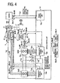
- Fig. 4 is a block diagram showing a system construction of a vehicle drive control system for controlling the gear train.
- This vehicle control system is constructed to include: a vehicle control unit U as a main component; a shift position sensor Sn1, a brake pedal sensor Sn2 and an accelerator pedal sensor Sn3 as input means for inputting demands of the driver to the vehicle control unit; various sensors (e.g., a generator rotor position sensor Sn4 or a drive motor rotor position sensor Sn5) as input means for inputting various pieces of information of the running situation of the vehicle; a battery B as a power source; a drive motor inverter InM as means for driving the drive motor 3; and a generator inverter InG for driving the generator 2.
- a vehicle control unit U as a main component
- a shift position sensor Sn1, a brake pedal sensor Sn2 and an accelerator pedal sensor Sn3 as input means for inputting demands of the driver to the vehicle control unit
- various sensors e.g., a generator rotor position sensor
- the vehicle control unit U is a control unit composed of a CPU, a memory and so on for controlling the vehicle as a whole, and is provided with an engine control unit U E , a generator control unit U G and a drive motor control unit U M .
- the engine control unit U E is composed of a CPU, a memory and so on and is connected through a signal line L E with the engine 1 for sending a command signal such as a throttle opening ⁇ or a fuel injection rate so as to control the engine 1.
- the generator control unit U G is connected through a signal line L G with the inverter InG for sending a control signal to the inverter InG so as to control the generator 2 made of a three-phase AC electric motor (e.g., a permanent magnet type synchronous motor).
- the drive motor control unit U M is connected through a signal line L M with the inverter InM for sending a control signal to the inverter InM so as to control the dive motor 3 made of a three-phase electric motor.
- the two inverters inverter InG and InM are connected through a DC power line L S with the battery B and through three-phase (i.e., three phases U, V and W) AC power lines L A G and L A M with the three-phase coils of the individual stators 21 and 31 of the drive motor 3 and the generator 2.
- reference letters Cn designate a smoothing capacitor for smoothing the DC voltage of the DC power line L S by suppressing its fluctuations.
- the inverter InG is so controlled on the basis of a PWM (Pulse Width Modulation) signal outputted by the generator control unit U G to the signal line L G as to convert the DC current fed from the battery B through the DC power line L S , into electric currents I UG , I VG and I WG of the individual U, V and W phases thereby to send the individual currents I UG , I VG I WG through the three-phase AC power line L A G to the three-phase coils of the generator 2.
- PWM Pulse Width Modulation
- the inverter InG is fed with the currents I UG , I VG and I WG of the individual phases U, V and W, as generated in-the three-phase coils of the generator 2, through the three-phase AC power line L A G, and converts them into DC electric currents and sends the DC currents to the battery B through the DC power line L S .
- the inverter InM is so controlled on the basis of a control signal outputted by the drive motor control unit U M to the signal line L M as to convert the DC current fed from the battery B through the DC power line L S , into electric currents I UM , I VM and I WM of the individual U, V and W phases thereby to send the individual currents I UM , I VM I WM through the three-phase AC power line L A M to the three-phase coils of the dive motor 3.
- the inverter InM is fed with the currents I UM , I VM and I WM of the individual phases U, V and W, as generated in the three-phase coils of the drive motor 3, through the three-phase AC power line L A M, and converts them into DC electric currents and sends the DC currents to the battery B through the DC power line L S .
- a battery sensor detects the states including the battery B, i.e., a battery voltage (V B ), a battery current (I B ), a battery temperature and a battery residue (SOC: State Of Charge), and inputs these pieces of information to the generator control unit U G and the drive motor control unit U M .
- An engine speed sensor Sn6 detects the engine speed (N E ).
- the shift position sensor Sn1 detects a shift position (SP) of the not-shown speed selecting means.
- the accelerator pedal sensor Sn3 detects the position of the accelerator pedal, i.e., a depression (AP).
- the brake pedal sensor Sn2 detects the position of the brake pedal, i.e., a depression (BP).
- An engine temperature sensor Sn7 detects the temperature (t E ) of the engine 1.
- a generator temperature sensor Sn8 detects the temperature (t G ) of the generator 2 in terms of the temperature of the coil, for example.
- a drive motor temperature sensor Sn9 detects the temperature (t M ) of the dive motor 3 in terms of the temperature of the coil, for example.
- the individual current sensors Sn10 to Sn12 of the three-phase AC power lines L A G and L A M are current sensors for detecting the current values I UG , I VG , I UM and I VM of the two in the three phases.
- this vehicle control unit U performs various processing operations: to send an engine control signal to the engine control unit U E thereby to set the drive/stop of the engine 1, as will be detailed; to read the rotor position ( ⁇ G ) of the generator 2 thereby to calculate the motor sped (N G ); to calculate the engine speed (N E ) by the aforementioned speed relation (1); to set the engine control unit U E with an engine target speed (N E *) indicating the target value of the engine speed (N E ); to set the generator control unit U G with a generator target speed (N G *) and a generator target torque (T G *); and to set the drive motor control unit U M with a drive motor target torque (T M *) and a drive motor torque correction value ( ⁇ T M ).
- the engine speed (N E ) is calculated by the vehicle control unit U but can also be read from the engine speed sensor Sn6.
- a vehicle speed (V) is calculated on the basis of the rotor position ( ⁇ M ) of the dive motor 3 but can also be calculated on the basis the ring gear speed (N R ) of the planetary 6 or the speed of the wheel 9.
- a ring gear speed sensor, a wheel speed sensor and so on are arranged as the vehicle speed detecting means.
- the vehicle control unit U is further provided with an oil pressure circuit L F for controlling the oil pressure of the brake 7 of the gear train and for lubricating and cooling the individual portions of the mechanism, and a hydraulic control unit for controlling the former, but the details of those circuit and unit are omitted from the Drawings.
- Fig. 5 and Fig. 6 divide and show a main flow of the control by the vehicle control unit U.
- the accelerator pedal position (AP) is inputted from the accelerator pedal sensor Sn3
- the brake pedal position (BP) is inputted from the brake pedal sensor Sn2.
- the rotor position ( ⁇ M ) is read from the rotor position sensor Sn5 of the dive motor 3 so that the vehicle speed (V) is calculated from the changing rate of the rotor position ( ⁇ M ).
- the vehicle speed (V) can also be calculated in another embodiment, as described hereinbefore, by providing a vehicle speed sensor separately to read it.
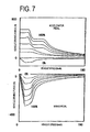
- a vehicle demand torque (T OUT *) is determined.
- the vehicle demand torque (T OUT *) preset to correspond to the accelerator position, the brake pedal position and the vehicle speed is determined by referring the vehicle demand torque map stored in the memory of the vehicle control unit U and shown in the upper stage of Fig. 7, when the accelerator pedal is depressed so that the accelerator pedal position (AP) is inputted, and by referring the vehicle demand torque map stored likewise in the memory and shown in the lower stage of Fig. 7, when the brake pedal is depressed so that the brake pedal position (BP) is inputted.
- Step S4 it is decided whether or not the vehicle demand torque (T OUT *) set at the preceding Step is higher than the dive motor maximum torque which is rated in advance in the dive motor 3. If this decision holds (YES), the torque becomes short. Therefore, the routine advances to Step S9, at which it is decided whether or not the engine 1 is stopped. In the case of the engine stop at which the decision holds (YES), the driving force cannot be assisted by the engine 1 so that an abrupt acceleration control subroutine of Step S10 is executed. In this case, both the dive motor 3 and the generator 2 are driven to make the run in a parallel mode, as will be detailed.
- Step S4 If it is decided at Step S4 that the vehicle demand torque (T OUT *) is no more than the drive motor maximum torque, on the other hand, the routine advances to Step S5, at which driver demand output (P D ) is calculated.
- a battery charge/discharge demand output (P B ) is inputted. This output is calculated on the basis of a battery residue (SOC) read from the signal line L B of the battery sensor.
- Step SOC battery residue
- the running point i.e., an engine target torque T E * and an engine target speed N E *
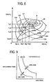
- the engine target running state map stored in the memory of the vehicle control unit U and shown in Fig.
- the points (A1 to A3, A min ), at which broken curves C1 to C3 indicating the vehicle demand output (P OUT ) and the engine operating curve (i.e., a contour curve joining the running points for the highest efficiencies of the engine 1) at individual accelerator pedal positions ( ⁇ 1 % to ⁇ 6 %) intersect, are determined as the running points of the engine 1; the engine torques (T E 1 to T E 3, T E min) at the running points are determined as the engine target torque (T E *); and the engine speeds (N E 1 to N E 3, N E min) at those running points are determined as the engine target speed (N E *).
- Step S11 it is decided at nest Step S11 whether or not the engine is in the running range. This decision is made by judging it, from the vehicle demand torque (T OUT *) and the vehicle speed (V) determined at preceding Steps with reference to the engine running range map stored in the memory of the vehicle control unit U and shown in Fig. 9, whether or not the engine 1 is in the running range.
- T OUT * vehicle demand torque
- V vehicle speed
- a curve crossing an arrow indicating OFF ⁇ ON is a boundary line on which the stopped engine is started; a curve crossing an arrow indicating ON ⁇ OFF is a boundary line on which the running range is stopped; the intermediate region is a hysteresis region for holding the stability of the control; and the side on which the vehicle speed or vehicle demand torque is higher than that in the hysteresis region is the engine running range whereas the lower side is the engine stop range.
- the curve crossing the arrow indicating OFF ⁇ ON for starting the engine is shifted the more rightward of the Drawing for the more battery residue (SOC) thereby to narrow the engine running range, and is shifted the more leftward for the less battery residue SOC thereby to widen the running range.
- Step S11 determines whether or not the engine is running. If this decision does not hold (NO), the engine 1 is not run although it is in the running range. At Step S26, therefore, there is executed the (later-described) engine start control subroutine. If the engine running range decision does not holds (NO) at the stage of Step S11, on the other hand, the routine transfers to Step S24, at which it is separately decided whether or not the engine is running. If this decision holds (YES), moreover, the engine is run although it is in the stop range. At next Step S25, therefore, there is executed the (later-described) engine stop control subroutine.
- Step S13 If the routine is returned to Step S12 at which the decision of the engine running holds (YES), the engine control subroutine is executed at Step S13. This processing is well known in the art so that the description and illustration of its specific contents are omitted.
- the generator target speed (N G *) is determined. This determination is made from the vehicle speed (V: determined from the changing rate of the rotor position ⁇ M of the dive motor 3 in the present embodiment) and the engine target speed (N E *) by using the foregoing speed relation (1) of the planetary.
- Step S15 it is decided whether or not the absolute value of the generator target speed (N G *) exceeds a first predetermined value (e.g., 500 [rpm]). This decision is made for the later selection of ON and OFF of the generator brake so as to reduce the energy loss.
- a first predetermined value e.g. 500 [rpm]
- the generator brake 7 is applied to stop the generator 2 mechanically thereby to improve the fuel economy.
- Step S16 If this decision holds (YES), moreover, the OFF state of the generator brake is confirmed at next Step S16. If this holds, the (later-described) generator speed control subroutine is executed at Step S17. Otherwise, the routine transfers to Step 23, at which there is executed the (later-described) generator brake OFF control subroutine. If the decision of preceding Step S15 does not hold, on the other hand, the ON state of the generator brake is confirmed at Step S21. If this confirmation does not hold, the generator brake ON control subroutine is executed at Step S22. If the confirmation holds, the routine returns to the steps after the generator speed control subroutine by Step S17.
- the drive shaft torque (T R ⁇ OUT ) to be outputted through the planetary is estimated at next Step S18.
- This processing is executed by estimating a ring gear torque (T R ) from a generator torque (T G ) with the foregoing torque balance equation (2) of the planetary and by calculating the drive shaft torque (T R ⁇ OUT ) considering the counter gear ratio.
- the engine torque T E , the ring gear torque T R and the generator torque T G receive reactions from one another, as described hereinbefore, so that the generator torque T G is converted into the ring gear torque T R and is outputted from the ring gear 62.
- the generator rotating speed N G and the ring gear torque T R fluctuate as the ring gear torque T R is outputted from the ring gear 62, the ring gear torque T R having fluctuated is transmitted to the wheel 9 thereby to degrade the running feeling of the vehicle. Therefore, the ring gear torque T R is calculated while estimating the torque of the inertia of the generator 2 accompanying the fluctuations of the generator speed N G .
- the ring gear torque T R is calculated on the basis of the generator target torque T G * and the aforementioned gear ratio ⁇ , by calculating the ring gear torque by the operation of the vehicle control unit U and by reading the generator target torque T G *.
- T G * + I G ⁇ ⁇ G
- T R can be calculated from the generator target torque T G *.
- This processing can also adopt, only when the generator brake is ON, a mode in which the ring gear torque (T R ) is estimated from the engine torque (T E : taught from the engine control unit) by using the torque balancing equation (2) of the planetary.
- Step S19 there is determined the drive motor target torque (T M *). This processing is determined from the difference between the vehicle demand torque (T OUT *) and the drive shaft torque (T R ⁇ OUT ). Finally, the drive motor control is made at Step S20, and the series of flows are ended to return to the initial Step. If the routine transfers to the abrupt acceleration control of Step S10, all the subsequent Steps are skipped to return directly to the initial Step, as shown by symbol B.
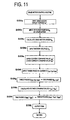
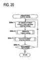
- the vehicle demand torque (T OUT *) determined at preceding Step S3 is inputted at Step S101, and the drive motor target torque (T M *) is set with the maximum torque of the drive motor at next Step S102.
- the differential torque between the vehicle demand torque (T OUT *) and the drive motor target torque (or drive motor maximum torque) (T M *) is calculated to set the shortage for the drive motor maximum torque as the generator target torque (T G *).
- the drive motor control is performed at next Step S104 according to the drive motor target torque (T M *), and the generator torque control is performed at Step S105 according to the generator target torque (T G *).
- the drive motor target torque (T M *) is inputted at Step S104a.
- the rotor position ( ⁇ M ) of the drive motor is inputted at Step S104b.
- These inputs may be detected with or without a position sensor such as a resolver.
- the drive motor speed (N M ) is calculated at Step S104c. This calculation can be made in this embodiment from the changing rate of the rotor position ( ⁇ M ) of the drive motor. In another embodiment, a rotation sensor can be separately adopted for the detection.
- the battery voltage (V B ) is inputted at Step S104d.
- Step S104e there are determined a d-axis current command value (I dM *) and a q-axis current command value (I qM *). These determinations are made with reference to the not-shown map from the drive motor target torque (T M *), the drive motor speed (N M ) and the battery voltage (V B ) inputted at preceding Steps. Subsequently, the three-phase AC currents (I UM , I VM , I WM ) are inputted at Step S104f.
- Step S104g there are made conversions of three phases (I UM , I VM , I WM ) ⁇ two phases (I dM , I qM ).
- the voltage command values (V dM *, V qM *) are so calculated at next Step S104h that the individual differences between (I dM , I qM ) and the d-axis current command value (I dM *) and the q-axis current command value (I qM *) may be reduced to 0.
- Step S104i there are made conversions of the two phases (V dM *, V qM *) ⁇ three phases (V UM *, V VM *, V WM *).
- the voltage command values (V UM *, V VM *, V WM *) thus determined are subjected to pulse width modulations and are outputted as the PWM (Pulse Width Modulation) signals to the inverter InM at Step S104j.
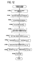
- the generator target torque (T G *) is inputted at Step S105a.
- the rotor position ( ⁇ G ) of the generator is inputted at Step S105b.
- These inputs may be detected with or without a position sensor such as a resolver.
- the generator speed (N G ) is calculated at Step S105c. This generator speed (N G ) is determined in this embodiment from the changing rate of the rotor position ( ⁇ G ) of the generator. In another embodiment, a rotation sensor can be separately adopted for the detection.
- the battery voltage (V B ) is inputted at Step S105d.
- Step S105e there are determined a d-axis current command value (I dG *) and a q-axis current command value (I qG *). These determinations are made with reference to the not-shown map from the generator target torque (T G *), the generator speed (N G ) and the battery voltage (V B ) inputted at preceding Steps. Subsequently, the currents (I UG , I VG , I WG ) are inputted at Step S105f.
- Step S105g there are made conversions of three phases (I UG , I VG , I WG ) ⁇ two phases (I dG , I qG ).
- the voltage command values (V dG *, V qG *) are so calculated at next Step S105h that the individual differences between (I dG , I qG ) and the d-axis current command value (I dG *) and the q-axis current command value (I qG *) may be reduced to 0.
- Step S105i there are made conversions of the two phases (V dG *, V qG *) / three phases (V UG *, V VG* , V WG *).
- the voltage command values (V UG *, V VG *, V WG *) thus determined are subjected to pulse width modulations and are outputted as the PWM (Pulse Width Modulation) signals to the inverter InG at Step S105j.
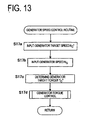
- Fig. 13 shows a flow of the generator speed control routine.
- the input of the generator target speed (N G *) is inputted at first Step S17a.
- the generator speed (N G ) is inputted at Step S17b.
- the generator target torque (T G *) is determined at Step S17c.
- This generator target torque (T G *) is determined by the PI control (in which the generator target torque (T G *) is made the larger considering its plus and minus for the larger difference between the generator target speed (N G *) and the generator speed (N G ) inputted at preceding Steps).
- the generator torque control is made at next Step S17d.
- the contents of the generator torque control of this case are similar to those described in the preceding generator torque control routine.
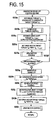
- Fig. 14 shows a flow of the generator brake ON control routine.
- the generator target speed (N G *) is set with 0 rpm at first Step S22a.
- the generator speed control is executed at Step S22b.
- the contents of this control are similar to those described in the preceding generator speed control routine.
- Step S22c there is estimated the drive shaft torque (T R ⁇ OUT ) which is outputted through the planetary.
- the drive motor target torque (T M *) is set with the estimated drive shaft torque (-T R ⁇ OUT ).
- the drive motor control is executed at next Step S22e.
- Step S22f the drive shaft torque (T R ⁇ OUT ) to be outputted from the generator through the planetary is so negated by the drive motor while the generator speed control is being executed at Step S22b that it may not be transmitted as shocks to the wheel.
- Step S22f it is decided at Step S22f whether or not the absolute value of the generator speed (N G ) is less than a second predetermined value (e.g., 100 [rpm]). So long as this decision does not hold, moreover, the loop returning to Step S22b is repeated.
- a second predetermined value e.g. 100 [rpm]
- Step S22f the routine advances to Step S22g, at which the generator brake is turned ON.
- the drive shaft torque (T R ⁇ OUT ) to be outputted through the planetary is estimated at Step S22h, and the drive motor target torque (T M *) is set with the estimated drive shaft torque (-T R ⁇ OUT ) at Step S22i.
- the drive motor control is executed at next Step S22j.
- the contents of this control are similar to those described in the preceding drive motor control routine.
- Step S22k the drive shaft torque (T R ⁇ OUT ) to be outputted from the generator through the planetary is so negated by the drive motor while the generator speed control is being executed at Step S22b that it may not be transmitted as shocks to the wheel.
- Step S22k it is decided at Step S22k whether or not a predetermined time has elapsed with the generator brake being ON. This timer decision is made as the standby time till the rotation of the generator is actually stopped by the generator brake ON.
- the SW (Switching) of the generator is stopped at next Step S221, and this routine is ended and returned.
- Fig. 15 shows a flow of the generator brake OFF control routine.
- the correspondence to the engine torque (T E ) is set with the generator target torque (T G *) at Step S23a, and the generator torque control is accordingly made at Step S23b.
- the drive shaft torque (T R ⁇ OUT ) to be outputted through the planetary is estimated at Step S23c, and the drive motor target torque (T M *) is set with the estimated drive shaft torque (-T R ⁇ OUT ) at next Step S23d.
- the drive motor control is executed at Step S23e.
- Step S23c the drive shaft torque (T R ⁇ OUT ) to be outputted from the generator through the planetary is so negated by the drive motor while the generator speed control is being executed at Step S23b that it may not be transmitted as shocks to the wheel.
- Step S23f a predetermined time has elapsed
- the routine returns to the generator torque control of Step S23b, and the subsequent operations are repeated.
- Step S23g the routine advances to next Step S23g, at which the generator brake is turned OFF.
- Step S23h the generator target speed (N G *) is set with 0 rpm.
- Step S23i the generator speed control is executed. The contents of this control are similar to those described in the preceding generator speed control routine. While the generator speed control being thus made, the drive shaft torque (T R ⁇ OUT ) to be outputted through the planetary is estimated at Step S23j, and the drive motor target torque (T M *) is accordingly set at Step S23k with the estimated drive shaft torque (-T R ⁇ OUT ). Finally, the drive motor control is executed at Step S231. The contents of this control are similar to those described in the preceding drive motor control routine.
- Step S23j the drive shaft torque (T R ⁇ OUT ) to be outputted from the generator through the planetary is so negated by the drive motor while the generator speed control is being executed at Step S23j that it may not be transmitted as shocks to the wheel.
- this routine is ended and returned.
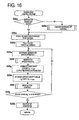
- Fig. 16 shows a flow of the engine stop control routine.
- Step S25a it is decided at first Step S25a whether or not the generator brake is OFF. If this decision does not hold, the generator brake OFF control is made at Step S25b to bring the generator into a rotatable state.
- Step S25c moreover, there are performed the operations to inject the fuel into the engine and to stop the ignition.
- Step S25g there is estimated the drive shaft torque (T R ⁇ OUT ) which is outputted in this state through the planetary.
- the drive motor target torque (T M *) is set with the estimated drive shaft torque (-T R ⁇ OUT ).
- the drive motor control is made at Step S25i. The contents of this control are also similar to those described in the preceding drive motor control routine.
- the drive shaft torque (T R ⁇ OUT ) to be outputted from the generator through the planetary is so negated by the drive motor while the generator speed control is being executed at Step S25f that it may not be transmitted as shocks to the wheel.
- the SW (Switching) of the generator is stopped at Step S25k, and this routine is ended and returned.
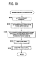
- Fig. 17 shows a flow of the engine start control routine.
- the operation to set the throttle opening to a default of 0 % is performed at first.
- the throttle opening 0 % is decided at first Step S26a. If this decision is not satisfied, the throttle opening is set to 0 % at Step S26b by the output of the engine control unit U E . Under this condition satisfied, moreover, the vehicle speed (V) is inputted at Step S26c.
- the running point e.g., the engine target torque T E *, the engine target speed N E *
- Step S26e the prepositioning control according to the gist of the present invention is made at next Step S26e.
- the generator target speed (N G *) is determined at Step S26f.
- Step S26g it is decided at Step S26g whether or not the engine speed (N E ) ⁇ the starting speed. This decision does not hold at first, and the routine transfers to Step S26h, at which the generator speed control is executed to raise the engine speed.
- the fluctuating torque negating control is made at Step S26i, and the routine returns to the Step S26c to input the vehicle speed (V).
- Step S26g holds so that it is confirmed that the conditions for the engine speed are satisfied.
- Step S26j the fuel is then injected to the engine, and the ignition is started. After this, there are made the generator speed control at Step S26k and the fluctuating torque negating control at Step S261. Moreover, the throttle opening is adjusted at Step S26m.
- Step S26n the engine start is confirmed by deciding whether or not the generator torque (T G ) ⁇ the motoring torque. After this, at final Step S26o, it is decided whether or not a predetermined time for waiting the stability of the engine speed has elapsed. When this decision holds, this routine is ended and returned.
- the engine start in the preceding engine start control is effected by causing the generator 2 to output a sufficient torque for running the engine 1 continuously (i.e., the control of Step S26h shown in Fig. 17), by deciding that the predetermined speed (e.g., the idling speed) is reached (i.e., the decision of Step S26g shown in Fig. 17), and by starting the fuel injection / the ignition (i.e., at Step S26k shown in Fig. 17).
- the generator angular velocity ⁇ G of the aforementioned case fluctuates with the engine rotating load.
- the crank-shaft position control for positioning the engine 1 being fuel-cut at a predetermined cranking starting position is made by the vehicle control unit U by motoring the generator 2.
- Fig. 18 shows the relation between the crank angle of a four-cylinder engine and a cranking torque schematically.
- This relation is determined mainly by synthesizing the relations (in which symbols ⁇ , ⁇ , ⁇ and X indicate the torques of individual cylinders) between the strokes of the pistons in the individual cylinders and the expansion/compression of the combustion chamber volume, as well known in the art.
- the cranking torque increases, when the compression advances in a specific cylinder, and-decreases when the top dead center is passed.
- the torque is characterized to grow extremely high at the rising time of the rotation but then to take a lower substantially constant value although having its fluctuations. Due to the dispersion of the crank angle determined by the state in which the engine is stopped, therefore, there highly fluctuates the cranking load for raising the rotation at the beginning of the cranking.
- the gist of the present invention resides in that the control to rotate the engine having stopped or to stop at the circled A position (indicating the general position to be naturally taken at the engine stop time because the rotation load is near substantially 0) to the circled B position (indicating the position which cannot be usually taken when the rotation load is so high that the engine naturally stops but which is not always limited to the close vicinity before the torque position the minimum necessary for causing the engine to continuously run over the first peak load, as indicated by a broken line), that is, the control (as termed herein as the "crank-shaft position control") is made prior to the cranking.
- the circled A position indicating the general position to be naturally taken at the engine stop time because the rotation load is near substantially 0
- the circled B position indicating the position which cannot be usually taken when the rotation load is so high that the engine naturally stops but which is not always limited to the close vicinity before the torque position the minimum necessary for causing the engine to continuously run over the first peak load, as indicated by a broken line
- the prepositioning control at which the present invention aims, is made in the state where none of the fuel injection and ignition of the engine and the adjustment of the throttle opening is done no matter whether the engine is being stopped or rotated. Therefore, the "engine being stopped in running", as termed in the present invention, implies the aforementioned state but does not always imply the engine being stopped in rotation.
- Fig. 19 shows a time chart of the control of a first embodiment of the prepositioning control.
- the crank-shaft position adjusting torque (T G p) is outputted to rotate the engine discontinuously from the Aposition to the B position, as specified hereinbefore, thereby to make the crank-shaft position control to the predetermined cranking starting position.
- This predetermined cranking starting position may be located, as will be described hereinafter, at a predetermined crank angle position by detecting it, may be warranted by a lapse of a constant time period by multiplying a predetermined torque lower than the torque necessary for starting the engine, or may combine them.
- the output shaft torque fluctuation is prevented by causing the motor to output the torque which is calculated by subtracting a negating torque (T M p) for reducing the generator torque component to 0 on the output shaft from the drive torque (i.e., the a for ementioned vehicle demand torque T OUT *) necessary for the vehicle to run.
- T M p negating torque
- T OUT * the drive torque
- Step S26f the generator is caused to output a cranking torque (T G c) sufficient for rotating the engine continuously, thereby to effect the engine start.
- T G c cranking torque
- the output shaft torque fluctuation is prevented by outputting the torque (T M c) for correcting the cranking torque to the drive motor.
- the drive shaft torque slightly fluctuates at the beginning of the cranking, as indicated by a solid curve, but can be suppressed lower at its peak value than the torque fluctuation of the cranking case from the A position, as indicated by a broken curve.
- This fluctuation is caused by the fluctuation of the cranking torque of the engine according to the crank angle, as shown in Fig. 18.
- the cranking torque (T G c) output according to that high torque load is high from the beginning so that the rise of the engine speed from the shown B position is quickened to shorten the time period for the torque fluctuation to occur.
- Fig. 20 shows a flow chart of the case in which the aforementioned-operations are done by a timer control.
- the generator target torque (T G *) is set with an arbitrary constant torque at Step S26e-1.
- the constant torque of this case is exemplified by 1.5 [Nm], i.e., a torque lower than that necessary for starting the engine.
- Step S26e-2 a generator torque control similar to the aforementioned one is made at Step S26e-2, and a fluctuating torque negating control is made at Step S26e-3.
- One pattern for the fluctuating torque negating control of this case is shown in a flow chart in Fig. 21.
- the drive shaft torque (T R ⁇ OUT ) to be outputted through the planetary is estimated at first Step S26e-31 by a method similar to the aforementioned one; the drive motor target torque (T M *) is set at Step S26e-32 with the torque for negating that torque simply, i.e., -T R ⁇ OUT ; and the drive motor control having contents similar to the aforementioned ones is accordingly executed at Step S26e-33.
- the decision on a predetermined time is thus made at final Step S26e-4.
- the predetermined time of this case is exemplified by 0.3 seconds.
- the correction torque to be set in the aforementioned drive motor target torque (T M *) can be set by the calculation, as described hereinbefore.
- the map of the correction torque in the drive motor as corresponding to the generator torque adjusted to an arbitrary constant torque, as shown in Fig. 22, could be set in the memory of the vehicle control unit U and used to set the correction torque.
- Fig. 23 is a flow chart showing the control contents of a second embodiment in which the aforementioned timer control is replaced by a detection of the crank-shaft position.
- the arbitrary constant torque to be set at first Step S26e-1 of this prepositioning control routine need not be necessarily made lower than the torque for the motoring but can be set to a higher value, e.g., 5 [Nm] than that of the foregoing first embodiment.
- the fluctuating torque negating control of Step S26e-3 of this case can adopt either of the two patterns as in the case of the foregoing first embodiment.
- Various sensors can be used for deciding the predetermined crank-shaft position at final Step S26e-5.
- a sensor having a high resolution and capable of detecting a detailed crank-shaft position or a sensor exemplifying a detector which is prepared by forming corrugations or notches according to the rotation of the crank-shaft on the circumference of a disc-shaped detector Sn21 or Sn22 for rotating synchronously with the crank-shaft, as shown in Fig. 24 or Fig. 25 (in which the corrugations or notches are formed at an interval of 180 degrees according to a four-cylinder engine having two predetermined crank-shaft positions for one rotation of the crank-shaft).
- Another method can be exemplified by a method for determining the speed signal from the engine by integrating it, or a method for determining the engine speed from the speeds of the generator and the drive motor by using the speed equation (1) of the planetary and by integrating it.
- Fig. 26 is a flow chart showing the control contents of the prepositioning control of a third embodiment.
- a crank-shaft position ( ⁇ ) is inputted at first Step S26e-6, and a time (t) till a predetermined crank-shaft position is reached is calculated at next Step S26e-7.
- the time (t) of this case can be either set in the memory of the vehicle control unit U as a map of the relation of the time (t) to the crank-shaft position ( ⁇ [degrees]), as shown in Fig. 27, or determined by calculations.
- the arbitrary torque to be set to the generator target torque of next Step S26e-1 is exemplified by 5 [Nm] as in the foregoing case of the second embodiment.
- the decision of the crank-shaft position is made by deciding the lapse of the time (t) at final Step S26e-8.
- the remaining Steps are similar to those of the foregoing first and second embodiments.
- Fig. 28 is a flow chart showing the control contents of the prepositioning control of a fourth embodiment.
- the torque for setting the crank-shaft position is made variable.
- the crank-shaft position ( ⁇ ) is inputted at first Step S26e-6 as in the preceding third embodiment.
- the generator target torque (T G *) is set according to the crank-shaft position. This setting is made by setting the map of the generator target torque (T G *), as made variable along the cranking torque (as referred to Fig. 18), as shown in Fig. 29, in the memory of the vehicle control unit.
- the fluctuating torque negating control of this case can be corrected not only according to the aforementioned flow of Fig. 20 but also separately by a first torque correcting map, as shown in Fig. 29.
- This first torque correcting map is one for the drive motor target torque (T M * ) which simply negates the generator target torque (T G *) by a variable torque map while considering the gear ratio.
- the engine after the prepositioning control is motored by the speed control (as referred to Step S23k of Fig. 17) of the generator.
- the generator output is different depending upon the temperature. This different may be unable to be corrected even if the torque negating the fluctuating torque during the motoring is mapped.
- a complicated control such as a separate temperature correcting control.
- a more precise torque correction is expected in a simple control by motoring in the torque control of the generator and by mapping the corresponding negating torque.
- the difference between the engine start control routine shown in Fig. 30 and the engine start control routine shown in Fig. 17 resides essentially in the difference of the torque control from the aforementioned speed control of the generator. By designating the corresponding steps by similar step numbers, therefore, the description will be directed to only the differences but not to the common portions.
- the contents of the generator torque control of Steps S26q and S26s in this embodiment are similar to those described before with reference to Fig. 12.
- the fluctuating torque negating controls of Steps S26r and S26t have the following correction patterns, although the foregoing correction method shown in Fig. 21 is the first correction pattern (as will be called the "ordinary correction pattern").
- a second correction pattern is one according to the generator torque negating map, the flow of which is shown in Fig. 31.
- the drive motor control is made by determining the generator torque to occur at the motoring time experimentally by the speed control of the generator, by mapping the drive motor target torque (T M *) to negate the generator torque simply and by setting the drive motor target torque (T M *).
- a third correction pattern is a correction by the ordinary correction pattern and drive shaft torque fluctuation negating map according to the crank-shaft position, as shown in Fig. 33. Therefore, this correction pattern premises the use of the sensor having a high resolution and capable of detecting a detailed position.
- the drive motor target torque (T M *) is set with respect to the crank-shaft position ( ⁇ [degrees]), thereby to negate the cranking torque which fluctuates according to the crank angle indicated by the output shaft torque (in a solid curve) in Fig. 19.
- the map shown in Fig. 35 has a setting including the torque fluctuation at the engine ignition time, and the fluctuation of the drive shaft torque can be eliminated substantially completely by that correction.
- a fourth correction pattern is a combination of the correction by the generator torque negating map and the correction by the drive shaft torque negating map according to the crank-shaft position, as shown in Fig. 36.
- the drive motor target torque (T M *) of the torque correction map by this correction, as shown in Fig. 37, is set as a sum of the torque values referring to the map shown in Fig. 32 and the map shown in Fig. 34.
- the engine start control routine of Fig. 38 shows a sixth embodiment, in which an operation to inhibit the prepositioning control is added when the vehicle demand torque is higher than that of the foregoing engine start control routine shown in Fig. 17.
- the input of the vehicle demand torque (T OUT *) of Step S26u is added after the input step of the vehicle speed (V), and the decision of Step S26v on the vehicle demand torque (T OUT *) ⁇ a predetermined torque is added after the input of the running points of the engine. If this decision does not hold, the flowskips the prepositioning control.
- the remaining flow is similar to that of the engine start control routine of the first embodiment shown in Fig. 17, the description will be omitted by designating the corresponding steps by similar step numbers.
- Fig. 39 is a time chart showing a seventh embodiment for this treatment.
- the engine being run in the fuel cut state is controlled to be quickly stopped by causing the generator to absorb the torque.
- the drive motor is caused to output the correction torque to reduce the generator torque to 0 on the output shaft.
- the engine is abruptly decelerated from the idling run so that the fluctuation of the output shaft torque is caused at a speed just before the stop by the torque fluctuation.
- Fig. 40 is a flow chart showing the control contents described above.
- the engine stop control routine of Step S25 in the first embodiment is partially replaced by a prepositioning control. Specifically, Steps S25g to S25i of the portions relating to the drive motor control are replaced by the fluctuating torque negating control of Step S251, and a prepositioning control step of Step S25m is added before the final Step S25k.
- the torque correction pattern in the fluctuating torque negating control of this case can be exemplified by an ordinary correction pattern as in the case of the first embodiment.
- the torque correction pattern in the prepositioning control can also be exemplified by an ordinary correction pattern as in the first embodiment.
- the crank-shaft position control prior to the engine start is not required so that a quick response for starting the cranking of the engine directly at an arbitrary timing can be made even in case the drive demand of the driver changes just after the engine stop.
- the torque vibrations in this case can be reduced like the case of the first embodiment by the crank-shaft position control made in advance at the engine stop time.
- Fig. 41 to Fig. 43 are time charts showing the actual measurements comparing the engine start of the prior art and the engine start control accompanied by the prepositioning control according to the present invention, so as to verify the effects of the prepositioning control according to the present invention. All these time charts illustrate the data in the vehicle stop state with a view to preventing the complicated waveforms to facilitate the references.
- the motoring by the generator abruptly starts (as referred to the changes in the generator torque and the generator speed from 2.8 sees.) so that the crank-shaft vigorously rotates till the compression stroke end (as likewise referred to the torque peak of 3.2 secs.) of the highest load.
- the motoring gradually proceeds so that the rotation of the generator is caused to drop at an instant (as referred to the position of 3.1 secs.) by the bounce from the damper.
- the difference between the generator target speed and the actual generator speed grows so large as to establish a state in which the actual generator speed follows the target value.
- the generator speed abruptly rises. It is found that the rise causes a high torque fluctuation on the drive shaft (as referred to the rising gradient of the drive shaft torque of 3.1 secs. to 3.2 secs.). After this, the torque is irregularly disturbed to fluctuate without converging for a long time.
- the crank-shaft position control starts near 3.7 secs. (as referred to the change in the generator torque) and ends near 4.1 secs., and that the cranking is started from that position so that the fall of the generator speed is suppressed to a remarkably-small value in the vicinity of 4.3 secs.
- the torque fluctuation to occur in the drive shaft torque is effectively reduced.
- no subsequent disturbance occurs in the torque fluctuation of the drive shaft.
- crank-shaft position control to start near 15.3 secs. is substantially negligibly small with respect to the occurrence of the drive shaft torque fluctuation by the preceding engine stopping operation.
- the second embodiment in which the prepositioning control is made at the engine stop time, could be constructed such that the prepositioning control is made at a suitable timing after the engine stop.
- the timing of this case is proper for the engine position control without giving any physical disorder to the driver, if it is made to the instant when the drive torque change is controlled for the accelerator manipulation or brake manipulation for the driver to change the drive demand.
- the application of the invention has been described by enumerating the hybrid drive apparatus using the engine and the electric motor as its power source.
- the application of the present invention should not be limited thereto but could be employed a system for stopping/starting the engine automatically so as to prevent the unnecessary idling when the vehicle stops.
- the drive apparatus according to the present invention is suitably used as a drive apparatus for various automobiles mounting an engine and an electric motor.
Landscapes
- Engineering & Computer Science (AREA)
- Mechanical Engineering (AREA)
- Chemical & Material Sciences (AREA)
- Combustion & Propulsion (AREA)
- Transportation (AREA)
- General Engineering & Computer Science (AREA)
- Power Engineering (AREA)
- Life Sciences & Earth Sciences (AREA)
- Sustainable Development (AREA)
- Sustainable Energy (AREA)
- Automation & Control Theory (AREA)
- Electric Propulsion And Braking For Vehicles (AREA)
- Hybrid Electric Vehicles (AREA)
- Control Of Vehicle Engines Or Engines For Specific Uses (AREA)
Applications Claiming Priority (3)
| Application Number | Priority Date | Filing Date | Title |
|---|---|---|---|
| JP2000209587 | 2000-07-11 | ||
| JP2000209587 | 2000-07-11 | ||
| PCT/JP2001/006021 WO2002004806A1 (fr) | 2000-07-11 | 2001-07-11 | Systeme d'entrainement |
Publications (3)
| Publication Number | Publication Date |
|---|---|
| EP1300587A1 true EP1300587A1 (de) | 2003-04-09 |
| EP1300587A4 EP1300587A4 (de) | 2007-06-13 |
| EP1300587B1 EP1300587B1 (de) | 2010-10-06 |
Family
ID=18705969
Family Applications (1)
| Application Number | Title | Priority Date | Filing Date |
|---|---|---|---|
| EP01949946A Expired - Lifetime EP1300587B1 (de) | 2000-07-11 | 2001-07-11 | Hybrides antriebssystem |
Country Status (6)
| Country | Link |
|---|---|
| US (1) | US7023150B2 (de) |
| EP (1) | EP1300587B1 (de) |
| JP (1) | JP3903918B2 (de) |
| KR (1) | KR100743132B1 (de) |
| DE (1) | DE60143199D1 (de) |
| WO (1) | WO2002004806A1 (de) |
Cited By (1)
| Publication number | Priority date | Publication date | Assignee | Title |
|---|---|---|---|---|
| WO2008020184A1 (en) * | 2006-08-14 | 2008-02-21 | Nexxtdrive Limited | A method of operating a supercharger |
Families Citing this family (55)
| Publication number | Priority date | Publication date | Assignee | Title |
|---|---|---|---|---|
| DE10129448A1 (de) * | 2001-06-19 | 2003-01-02 | Bosch Gmbh Robert | Verfahren und Vorrichtung zur Überwachung einer Antriebseinheit eines Fahrzeugs und/oder ihr zugeordneter Komponenten |
| US6734647B2 (en) * | 2001-10-30 | 2004-05-11 | Honda Giken Kogyo Kabushiki Kaisha | Working machine |
| JP3997787B2 (ja) * | 2002-01-30 | 2007-10-24 | 株式会社デンソー | 車両統合制御システム |
| JP3466600B1 (ja) * | 2002-07-16 | 2003-11-10 | 本田技研工業株式会社 | ハイブリッド車両の制御装置 |
| JP3958274B2 (ja) * | 2003-10-10 | 2007-08-15 | アイシン・エィ・ダブリュ株式会社 | 放電制御装置、放電制御方法及びそのプログラム |
| JP4596381B2 (ja) * | 2004-02-02 | 2010-12-08 | アイシン・エィ・ダブリュ株式会社 | 電動車両駆動制御装置及び電動車両駆動制御方法 |
| US7495403B2 (en) * | 2004-03-30 | 2009-02-24 | Continental Automotive Systems Us, Inc. | Method, apparatus and article for vibration compensation in electric drivetrains |
| JP2005333690A (ja) * | 2004-05-18 | 2005-12-02 | Denso Corp | ハイブリッド車の制御装置 |
| US7378808B2 (en) * | 2004-05-25 | 2008-05-27 | Caterpillar Inc. | Electric drive system having DC bus voltage control |
| JP4135681B2 (ja) * | 2004-06-02 | 2008-08-20 | トヨタ自動車株式会社 | 動力出力装置およびこれを搭載するハイブリッド車並びにこれらの制御方法 |
| DE102005034794A1 (de) * | 2004-07-23 | 2006-02-23 | Ford Global Technologies, LLC, Dearborn | Verfahren zum Dämpfen von Vibrationen im Antriebsstrang eines hybridelektrischen Fahrzeugs |
| US20060047400A1 (en) * | 2004-08-25 | 2006-03-02 | Raj Prakash | Method and apparatus for braking and stopping vehicles having an electric drive |
| DE112005002717B4 (de) * | 2004-10-27 | 2019-07-18 | Toyota Jidosha Kabushiki Kaisha | Steuervorrichtung für Fahrzeugantriebssystem |
| US7161316B2 (en) * | 2004-11-02 | 2007-01-09 | General Electric Company | Method and apparatus for discrete speed compensated torque step motor control |
| US7512466B2 (en) * | 2005-06-30 | 2009-03-31 | Honeywell International Inc. | High-torque, low power reaction wheel array and method |
| US7578361B2 (en) * | 2005-08-11 | 2009-08-25 | Deere & Company | Differential steering assist system for utility vehicle |
| EP1760297B1 (de) * | 2005-09-06 | 2012-01-04 | Honda Motor Co., Ltd. | Steuerungssystem eines Verbrauchers und Steuerungssystem eines Maschinenstarts |
| US7560888B2 (en) * | 2005-09-08 | 2009-07-14 | Honeywell International Inc. | Electromechanical actuator including redundant, dissimilar position feedback |
| JP4193839B2 (ja) | 2005-12-19 | 2008-12-10 | トヨタ自動車株式会社 | 動力出力装置及びそれを搭載した車両 |
| WO2007138645A1 (ja) * | 2006-05-25 | 2007-12-06 | Mitsubishi Electric Corporation | 車両用補助電源装置 |
| US7722498B2 (en) * | 2006-06-21 | 2010-05-25 | Denso Corporation | Control device and method for hybrid electric vehicle |
| JP4396717B2 (ja) * | 2007-03-07 | 2010-01-13 | トヨタ自動車株式会社 | 車両の制御装置、制御方法、その方法を実現させるプログラムおよびそのプログラムを記録した記録媒体 |
| DE102007019941A1 (de) * | 2007-04-27 | 2008-11-06 | Robert Bosch Gmbh | Verfahren zum Positionieren einer Kurbelwelle einer abgeschalteten Brennkraftmaschine eines Kraftfahrzeugs |
| US8261864B2 (en) * | 2008-06-17 | 2012-09-11 | GM Global Technology Operations LLC | Hybrid powertrain auto start control system with engine pulse cancellation |
| JP4631936B2 (ja) * | 2008-06-18 | 2011-02-16 | トヨタ自動車株式会社 | 動力出力装置およびその制御方法並びに車両 |
| JP5152003B2 (ja) * | 2009-01-19 | 2013-02-27 | 株式会社アドヴィックス | 前後加速度制御装置 |
| EP2426024B1 (de) * | 2009-04-27 | 2015-03-11 | Toyota Jidosha Kabushiki Kaisha | Hybrid-pkw und steuerverfahren dafür |
| US20100276218A1 (en) * | 2009-04-29 | 2010-11-04 | Ford Global Technologies, Llc | Hybrid electric vehicle powertrain having high vehicle speed engine starts |
| JP2011127504A (ja) * | 2009-12-17 | 2011-06-30 | Mitsubishi Electric Corp | エンジンの自動始動装置 |
| JP5521723B2 (ja) * | 2010-04-14 | 2014-06-18 | トヨタ自動車株式会社 | ハイブリッド車両のエンジン始動制御装置 |
| US8660726B2 (en) | 2010-06-24 | 2014-02-25 | GM Global Technology Operations LLC | Torque blending systems for hybrid electric vehicles with electrically continuous variable transmissions |
| US9010469B2 (en) * | 2010-08-30 | 2015-04-21 | Mitsubishi Jidosha Kogyo Kabushiki Kaisha | Generation control device |
| JP5899611B2 (ja) * | 2010-10-20 | 2016-04-06 | トヨタ自動車株式会社 | ハイブリッド車両の制御装置 |
| US9352739B2 (en) * | 2011-02-15 | 2016-05-31 | GM Global Technology Operations LLC | Method for operating a hybrid vehicle |
| WO2012114509A1 (ja) * | 2011-02-25 | 2012-08-30 | スズキ株式会社 | ハイブリッド車両のエンジン始動制御装置 |
| JP5842486B2 (ja) * | 2011-09-07 | 2016-01-13 | トヨタ自動車株式会社 | エンジン始動制御装置 |
| JP2013121231A (ja) * | 2011-12-07 | 2013-06-17 | Hitachi Automotive Systems Ltd | 電動車両の制御装置 |
| US9393954B2 (en) * | 2012-05-04 | 2016-07-19 | Ford Global Technologies, Llc | Methods and systems for engine stopping |
| DE102014204086A1 (de) * | 2013-07-15 | 2015-01-15 | Robert Bosch Gmbh | Verfahren und Vorrichtung zur Steuerung einer Brennkraftmaschine |
| US9246425B2 (en) * | 2014-04-29 | 2016-01-26 | Gulfstream Aerospace Corporation | Apparatus and systems for engine and generator control within an aircraft |
| JP6070669B2 (ja) * | 2014-10-02 | 2017-02-01 | トヨタ自動車株式会社 | エンジン停止装置 |
| US10001196B2 (en) * | 2014-12-19 | 2018-06-19 | Caleb Chung | Continuously variable transmission |
| US10774901B2 (en) | 2014-12-19 | 2020-09-15 | Caleb Chung | Continuously variable transmission |
| WO2016136795A1 (ja) * | 2015-02-27 | 2016-09-01 | 株式会社デンソー | エンジン始動装置及びエンジン始動方法 |
| JP2017043299A (ja) | 2015-08-28 | 2017-03-02 | トヨタ自動車株式会社 | ハイブリッド車両 |
| US10569758B2 (en) * | 2016-02-26 | 2020-02-25 | Ford Global Technologies, Llc | System and method for modeling and estimating engine cranking torque disturbances during starts and stops |
| CN109661339B (zh) * | 2016-08-24 | 2022-04-05 | 日立安斯泰莫株式会社 | 车辆控制装置 |
| KR101795306B1 (ko) * | 2016-10-07 | 2017-11-07 | 현대자동차주식회사 | 차량 시동 제어 방법 |
| US10148209B2 (en) * | 2017-03-01 | 2018-12-04 | Ford Global Technologies, Llc | System and method for in-vehicle resolver alignment |
| US10112598B1 (en) | 2017-09-21 | 2018-10-30 | Ford Global Technologies, Llc | System and method of controlling engine torque of hybrid vehicle |
| JP6881239B2 (ja) * | 2017-11-01 | 2021-06-02 | トヨタ自動車株式会社 | 内燃機関の制御装置 |
| TWI678058B (zh) * | 2018-03-06 | 2019-11-21 | 徐夫子 | 用於發電的阻尼系統 |
| CN109501568B (zh) * | 2018-12-28 | 2023-08-11 | 智一新能源发展有限公司 | 一种电动汽车双电机驱动系统及其控制方法 |
| KR20210045107A (ko) * | 2019-10-16 | 2021-04-26 | 현대자동차주식회사 | 차량 및 차량의 장치의 제어방법 |
| US11932116B1 (en) * | 2022-09-14 | 2024-03-19 | Borgwarner Inc. | Operating an electric drive system with low efficiency |
Citations (6)
| Publication number | Priority date | Publication date | Assignee | Title |
|---|---|---|---|---|
| EP0729858A1 (de) * | 1995-02-28 | 1996-09-04 | Kabushiki Kaisha Equos Research | Hybridfahrzeug |
| DE19532128A1 (de) * | 1995-08-31 | 1997-03-06 | Clouth Gummiwerke Ag | Antriebssystem, insbesondere für ein Kraftfahrzeug, und Verfahren zum Betreiben desselben |
| US5788006A (en) * | 1995-04-28 | 1998-08-04 | Kabushikikaisha Equos Research | Hybrid vehicle |
| WO1999015787A1 (de) * | 1997-09-19 | 1999-04-01 | Robert Bosch Gmbh | Antrieb eines kraftfahrzeuges |
| WO1999054621A1 (de) * | 1998-04-20 | 1999-10-28 | Continental Isad Electronic Systems Gmbh & Co. Kg | Verfahren und startersystem zum starten eines verbrennungsmotors |
| US6018198A (en) * | 1997-08-29 | 2000-01-25 | Aisin Aw Co., Ltd. | Hybrid drive apparatus for vehicle |
Family Cites Families (15)
| Publication number | Priority date | Publication date | Assignee | Title |
|---|---|---|---|---|
| EP0352323B1 (de) * | 1987-02-18 | 1994-06-01 | Hino Jidosha Kogyo Kabushiki Kaisha | Elektrische brems- und hilfsbeschleunigungsvorrichtung für fahrzeuge |
| JPH02286874A (ja) | 1989-04-28 | 1990-11-27 | Mitsubishi Motors Corp | レシプロエンジンの始動性向上装置 |
| JP3083310B2 (ja) * | 1990-01-26 | 2000-09-04 | 三菱電機株式会社 | 始動機能付エンジン動力伝達装置 |
| DE4430670B4 (de) * | 1993-09-02 | 2006-02-23 | Denso Corp., Kariya | Steuervorrichtung für einen elektrischen Generator/Motor für einen Verbrennungsmotor |
| JP3248827B2 (ja) * | 1995-01-18 | 2002-01-21 | 三菱電機株式会社 | エンジン発電機の制御装置 |
| US6148784A (en) * | 1995-08-31 | 2000-11-21 | Isad Electronic Systems Gmbh & Co. Kg | Drive systems, especially for a motor vehicle, and method of operating same |
| JP3129204B2 (ja) * | 1995-10-18 | 2001-01-29 | トヨタ自動車株式会社 | ハイブリッド駆動装置 |
| JP3454036B2 (ja) * | 1995-11-13 | 2003-10-06 | トヨタ自動車株式会社 | ハイブリッド駆動装置 |
| EP0781680B1 (de) * | 1995-12-27 | 2002-06-12 | Denso Corporation | Stromversorgungssteuervorrichtung für ein Hybrid-Fahrzeug |
| JPH09264235A (ja) * | 1996-03-29 | 1997-10-07 | Toyota Motor Corp | パワートレインの制御装置 |
| JP3250483B2 (ja) | 1996-07-18 | 2002-01-28 | トヨタ自動車株式会社 | 駆動装置 |
| JP3451935B2 (ja) * | 1998-06-03 | 2003-09-29 | 日産自動車株式会社 | ハイブリッド車両の駆動力制御装置 |
| JP3414310B2 (ja) * | 1998-09-25 | 2003-06-09 | トヨタ自動車株式会社 | エンジンの始動制御装置 |
| JP3498593B2 (ja) * | 1998-10-15 | 2004-02-16 | 日産自動車株式会社 | ハイブリッド車両の制御装置 |
| JP4244499B2 (ja) * | 2000-05-25 | 2009-03-25 | アイシン・エィ・ダブリュ株式会社 | ハイブリッド型車両の制御装置及び制御方法 |
-
2001
- 2001-07-11 EP EP01949946A patent/EP1300587B1/de not_active Expired - Lifetime
- 2001-07-11 DE DE60143199T patent/DE60143199D1/de not_active Expired - Lifetime
- 2001-07-11 WO PCT/JP2001/006021 patent/WO2002004806A1/ja active Application Filing
- 2001-07-11 JP JP2002509645A patent/JP3903918B2/ja not_active Expired - Fee Related
- 2001-07-11 US US10/069,395 patent/US7023150B2/en not_active Expired - Lifetime
- 2001-07-11 KR KR1020027003158A patent/KR100743132B1/ko active IP Right Grant
Patent Citations (6)
| Publication number | Priority date | Publication date | Assignee | Title |
|---|---|---|---|---|
| EP0729858A1 (de) * | 1995-02-28 | 1996-09-04 | Kabushiki Kaisha Equos Research | Hybridfahrzeug |
| US5788006A (en) * | 1995-04-28 | 1998-08-04 | Kabushikikaisha Equos Research | Hybrid vehicle |
| DE19532128A1 (de) * | 1995-08-31 | 1997-03-06 | Clouth Gummiwerke Ag | Antriebssystem, insbesondere für ein Kraftfahrzeug, und Verfahren zum Betreiben desselben |
| US6018198A (en) * | 1997-08-29 | 2000-01-25 | Aisin Aw Co., Ltd. | Hybrid drive apparatus for vehicle |
| WO1999015787A1 (de) * | 1997-09-19 | 1999-04-01 | Robert Bosch Gmbh | Antrieb eines kraftfahrzeuges |
| WO1999054621A1 (de) * | 1998-04-20 | 1999-10-28 | Continental Isad Electronic Systems Gmbh & Co. Kg | Verfahren und startersystem zum starten eines verbrennungsmotors |
Non-Patent Citations (1)
| Title |
|---|
| See also references of WO0204806A1 * |
Cited By (3)
| Publication number | Priority date | Publication date | Assignee | Title |
|---|---|---|---|---|
| WO2008020184A1 (en) * | 2006-08-14 | 2008-02-21 | Nexxtdrive Limited | A method of operating a supercharger |
| US9133761B2 (en) | 2006-08-14 | 2015-09-15 | Nexxtdrive Limited | Method of operating a supercharger |
| US9856782B2 (en) | 2006-08-14 | 2018-01-02 | Nexxtdrive Limited | Method of operating a supercharger |
Also Published As
| Publication number | Publication date |
|---|---|
| KR20020033174A (ko) | 2002-05-04 |
| US20020171383A1 (en) | 2002-11-21 |
| DE60143199D1 (de) | 2010-11-18 |
| EP1300587B1 (de) | 2010-10-06 |
| EP1300587A4 (de) | 2007-06-13 |
| US7023150B2 (en) | 2006-04-04 |
| JPWO2002004806A1 (ja) | 2004-01-08 |
| JP3903918B2 (ja) | 2007-04-11 |
| WO2002004806A1 (fr) | 2002-01-17 |
| KR100743132B1 (ko) | 2007-07-27 |
Similar Documents
| Publication | Publication Date | Title |
|---|---|---|
| EP1300587B1 (de) | Hybrides antriebssystem | |
| JP4518063B2 (ja) | 駆動装置 | |
| JP3958220B2 (ja) | トルク伝達装置 | |
| CN102639351B (zh) | 混合动力车辆及其控制方法 | |
| JP4670882B2 (ja) | 電動機駆動制御装置、それを備えた車両および電動機駆動制御方法 | |
| US6380640B1 (en) | Method of controlling power output apparatus | |
| US7854680B2 (en) | Control device and control method for power train | |
| US8718854B2 (en) | Electrically-powered vehicle and method for controlling the same | |
| US8125169B2 (en) | Rotating electrical machine control system and vehicle drive system | |
| JP4661183B2 (ja) | モータ駆動装置 | |
| US7406939B2 (en) | Engine vibration suppression device and suppression method thereof | |
| US8052571B2 (en) | Control device and control method for hybrid vehicle | |
| WO2009116215A1 (ja) | 電動機駆動制御装置、それを備えた車両および電動機駆動制御方法 | |
| WO2012133220A1 (ja) | 制御装置 | |
| EP1283122A2 (de) | Antriebsregelvorrichtung und Verfahren für ein Fahrzeug des Typs Hybrid und zugehöriges Programm | |
| WO2010013534A1 (ja) | 回転電機制御システム及び当該回転電機制御システムを備えた車両駆動システム | |
| JP6500872B2 (ja) | 駆動装置および自動車 | |
| JP3454167B2 (ja) | ハイブリッド車両の制御装置 | |
| JP3748397B2 (ja) | 電気自動車の制御装置 | |
| JPH10331674A (ja) | 車両用複合駆動システムの制御装置 | |
| JP5741030B2 (ja) | ハイブリッド車両およびその制御方法 |
Legal Events
| Date | Code | Title | Description |
|---|---|---|---|
| PUAI | Public reference made under article 153(3) epc to a published international application that has entered the european phase |
Free format text: ORIGINAL CODE: 0009012 |
|
| 17P | Request for examination filed |
Effective date: 20020717 |
|
| AK | Designated contracting states |
Kind code of ref document: A1 Designated state(s): AT BE CH CY DE DK ES FI FR GB GR IE IT LI LU MC NL PT SE TR |
|
| RBV | Designated contracting states (corrected) |
Designated state(s): AT BE CH CY DE FR GB IT LI |
|
| A4 | Supplementary search report drawn up and despatched |
Effective date: 20070510 |
|
| 17Q | First examination report despatched |
Effective date: 20071001 |
|
| GRAP | Despatch of communication of intention to grant a patent |
Free format text: ORIGINAL CODE: EPIDOSNIGR1 |
|
| RTI1 | Title (correction) |
Free format text: HYBRID DRIVE DEVICE |
|
| RBV | Designated contracting states (corrected) |
Designated state(s): DE FR GB IT |
|
| GRAS | Grant fee paid |
Free format text: ORIGINAL CODE: EPIDOSNIGR3 |
|
| GRAA | (expected) grant |
Free format text: ORIGINAL CODE: 0009210 |
|
| AK | Designated contracting states |
Kind code of ref document: B1 Designated state(s): DE FR GB IT |
|
| REG | Reference to a national code |
Ref country code: GB Ref legal event code: FG4D |
|
| REF | Corresponds to: |
Ref document number: 60143199 Country of ref document: DE Date of ref document: 20101118 Kind code of ref document: P |
|
| PLBE | No opposition filed within time limit |
Free format text: ORIGINAL CODE: 0009261 |
|
| STAA | Information on the status of an ep patent application or granted ep patent |
Free format text: STATUS: NO OPPOSITION FILED WITHIN TIME LIMIT |
|
| 26N | No opposition filed |
Effective date: 20110707 |
|
| REG | Reference to a national code |
Ref country code: DE Ref legal event code: R097 Ref document number: 60143199 Country of ref document: DE Effective date: 20110707 |
|
| PG25 | Lapsed in a contracting state [announced via postgrant information from national office to epo] |
Ref country code: IT Free format text: LAPSE BECAUSE OF FAILURE TO SUBMIT A TRANSLATION OF THE DESCRIPTION OR TO PAY THE FEE WITHIN THE PRESCRIBED TIME-LIMIT Effective date: 20101006 |
|
| REG | Reference to a national code |
Ref country code: FR Ref legal event code: PLFP Year of fee payment: 16 |
|
| REG | Reference to a national code |
Ref country code: FR Ref legal event code: PLFP Year of fee payment: 17 |
|
| REG | Reference to a national code |
Ref country code: FR Ref legal event code: PLFP Year of fee payment: 18 |
|
| PGFP | Annual fee paid to national office [announced via postgrant information from national office to epo] |
Ref country code: FR Payment date: 20200611 Year of fee payment: 20 |
|
| PGFP | Annual fee paid to national office [announced via postgrant information from national office to epo] |
Ref country code: GB Payment date: 20200701 Year of fee payment: 20 Ref country code: DE Payment date: 20200630 Year of fee payment: 20 |
|
| REG | Reference to a national code |
Ref country code: DE Ref legal event code: R071 Ref document number: 60143199 Country of ref document: DE |
|
| REG | Reference to a national code |
Ref country code: GB Ref legal event code: PE20 Expiry date: 20210710 |
|
| PG25 | Lapsed in a contracting state [announced via postgrant information from national office to epo] |
Ref country code: GB Free format text: LAPSE BECAUSE OF EXPIRATION OF PROTECTION Effective date: 20210710 |