EP1287753A1 - Übertragungsvorrichtung und Verfahren zum Übertragen von Artikeln der tabakverarbeitenden Industrie - Google Patents
Übertragungsvorrichtung und Verfahren zum Übertragen von Artikeln der tabakverarbeitenden Industrie Download PDFInfo
- Publication number
- EP1287753A1 EP1287753A1 EP02013365A EP02013365A EP1287753A1 EP 1287753 A1 EP1287753 A1 EP 1287753A1 EP 02013365 A EP02013365 A EP 02013365A EP 02013365 A EP02013365 A EP 02013365A EP 1287753 A1 EP1287753 A1 EP 1287753A1
- Authority
- EP
- European Patent Office
- Prior art keywords
- transfer
- transmission
- articles
- elements
- transport device
- Prior art date
- Legal status (The legal status is an assumption and is not a legal conclusion. Google has not performed a legal analysis and makes no representation as to the accuracy of the status listed.)
- Granted
Links
- 238000012546 transfer Methods 0.000 title claims abstract description 81
- 241000208125 Nicotiana Species 0.000 title claims description 19
- 235000002637 Nicotiana tabacum Nutrition 0.000 title claims description 19
- 238000000034 method Methods 0.000 title claims description 16
- 238000004519 manufacturing process Methods 0.000 claims abstract description 5
- 230000005540 biological transmission Effects 0.000 claims description 94
- 238000012545 processing Methods 0.000 claims description 19
- 238000003491 array Methods 0.000 claims 1
- 235000019504 cigarettes Nutrition 0.000 abstract description 8
- 230000002093 peripheral effect Effects 0.000 abstract 1
- 238000000926 separation method Methods 0.000 description 3
- 230000006978 adaptation Effects 0.000 description 1
- 230000015572 biosynthetic process Effects 0.000 description 1
- 238000005520 cutting process Methods 0.000 description 1
- 238000006073 displacement reaction Methods 0.000 description 1
- 238000009826 distribution Methods 0.000 description 1
- 230000002996 emotional effect Effects 0.000 description 1
- 238000012423 maintenance Methods 0.000 description 1
- 238000007726 management method Methods 0.000 description 1
- 210000000056 organ Anatomy 0.000 description 1
- 238000009964 serging Methods 0.000 description 1
- 238000003860 storage Methods 0.000 description 1
- 230000001360 synchronised effect Effects 0.000 description 1
- 238000012549 training Methods 0.000 description 1
Images


Classifications
-
- A—HUMAN NECESSITIES
- A24—TOBACCO; CIGARS; CIGARETTES; SIMULATED SMOKING DEVICES; SMOKERS' REQUISITES
- A24C—MACHINES FOR MAKING CIGARS OR CIGARETTES
- A24C5/00—Making cigarettes; Making tipping materials for, or attaching filters or mouthpieces to, cigars or cigarettes
- A24C5/47—Attaching filters or mouthpieces to cigars or cigarettes, e.g. inserting filters into cigarettes or their mouthpieces
- A24C5/478—Transport means for filter- or cigarette-rods in view of their assembling
Definitions
- the invention relates to a transmission device for Transferring articles of the tobacco processing industry from a first transport device to a second transport device, wherein the transfer device pivotable, each with a receptacle provided for an article, in the circumferential direction one behind the other arranged transmission elements comprises.
- the invention further relates to a method for transmitting of articles of the tobacco processing industry of recordings of a first transport device to Shooting a second transport device under Use of transmission elements at one end have a recording.
- a corresponding transfer device for rod-shaped Article is from DE 31 37 223 C2, the US 4,506,779 corresponds, known.
- articles of the Tobacco industry will be under this Invention, in particular cigarettes, filters, filter plugs, Filter cigarettes and the like the tobacco industry Understood.
- Filter attachment machines are the necessary for Filterzigarettenher too individual pieces like filter rods and cigarettes in peripherally sucking Grooves guided by rotating conveyor rollers.
- the Division of said grooves or recordings is based in certain areas of the Filteransetzmaschine on values like the beat of the cigarette machine and the bar feeder.
- the known from DE 31 37 223 C2 transmission device for rod-shaped articles consists of two at the same time rotating delivery cylinders attached to their Periphery each inserts of different pitch for the article, and a counter-rotating Transfer conveyor cylinder between the delivery cylinders is and these are the articles to each defined Transfer takes and transfers. It Here is a variety of lever-shaped end pieces provided, each with an arm with an insert for have the article.
- the transfer conveyor cylinder a second Dregangan on, the same as the and with the angular velocity of the first rotary organ rotates about an axis that is separate and parallel to the axis the first Dregangans lies, between the second Turning member and each lever-shaped end piece connecting means are provided, each having a connecting rod, that the respective lever-shaped tail and the second Dregangan joins together.
- the levers are locked before the article is picked up pivoted the transfer position to then from this wegverschwenkt, so that first a Throttling the speed is given to one relative speed in the ratio of zero between to allow the transmission elements.
- the object of the invention is achieved by training a transmission device for transmitting articles the tobacco processing industry from a first Transport device to a second transport device solved, wherein the transmission device pivotable, each with a recording for one Article provided circumferentially one behind the other arranged transmission elements comprises and wherein each at least two transmission elements axially arranged offset from each other.
- the transmission device comprises a Transmission element in particular an arm or rod.
- the transfer device and the transport devices are preferably drums.
- the first transport device, a feed conveyor and the second Transport device a discharge conveyor.
- the recordings of the first transport device have in a preferred embodiment, a relatively small pitch, whereas the shots the second transport device a relatively have large pitch.
- the shots of the Transmission device preferably have a variable Division on. This is due to the pivoting the one behind the other in the circumferential direction and axially mutually staggered transmission elements allows.
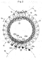
- the axially offset arranged at least two transmission elements at least two levels define, in which successively arranged transmission elements are arranged. From the perspective of Figs. 1 and 2 of this application are two levels of axially arranged transmission elements arranged one behind the other staggered, each pair of transmission elements - In the figure examples, two transmission elements - Are arranged offset axially.
- Axially offset means in particular querab to Movement level of the transmission device and one behind the other in the plane of movement of the transfer device.
- the at least two are axially offset arranged transmission elements independently and in particular differently pivotable. If this preferred embodiment is realized can a very effective separation or graduation of the transferring articles of the tobacco processing industry happen.
- the pictures of the first transport device are preferably at least two above the other or axially aligned arranged articles provided, the for example, shortly before the transfer area accordingly in two Articles from an article, for example, double use length were split or during or shortly after Handover to be parted.
- the respective axially offset Transmission elements define levels, where each level a cam is provided by means of which the transmission elements one associated with the cam body Level are pivotable, is a transmission device feasible, the only slight wear subject.
- the transfer device comprises a rotatable drum, by means of a particularly simple Embodiment of the invention is possible.
- a cam is designed such that at a movement of the transmission elements towards a first transfer station, where a recording of Articles by transmission elements of the transmission device allows the transmission elements in Direction of rotation or towards the first transfer station are swiveling, is a fast transfer device realizable.
- Under pitch is the distance of two shots understood which can be an integer multiple of ⁇ .
- the pivotability of the transmission elements of Transmission device is a variable pitch or a variable distance of the images of successively arranged transmission elements or the axially offset transmission elements possible.
- the at least one cam is such configured such that the transmission elements after the Transfer in the first transfer station against the Rotation are pivotable.
- the Curved bodies are designed such that at least partially an asynchronous movement of the transmission elements is possible, it is easily possible from a given pitch of the first Transport device to another pitch the second transport device rod-shaped article too transport or transfer. If that at least a transmission element in a movement towards a second transfer station, where a delivery of articles is made possible by the transmission elements in Direction of the second transfer station is pivotable, so that a staggering of the articles is possible is a particularly fast transmission possible.
- a particularly elegant embodiment is then given if the cam associated with the planes identical at least in the area of the first transfer station are shaped. This is a synchronous movement the superimposed transmission elements or pairs of transmission elements possible.
- the cam body designed in this way are that a different pivoting of the axial staggered transmission elements at least in Range of a second transfer station is possible is a particularly elegant graduation of at least two axially aligned arranged articles, which are in the Recordings of the first transport device are possible.
- the transmission elements With two axially aligned articles the transmission elements are in the range of the second Transfer station pulled apart in direction of rotation. at three axially aligned articles can, for example. the central transmission element radially, when the Transmission device is a drum, to the drum center be aligned. The other two Transmission elements are then in the direction of movement pivoted before and behind this central transmission element.
- the task is further by a staggering device for serging rod-shaped articles of tobacco processing Industrial, comprising at least one transport device with shots for each at least two axially aligned rod-shaped articles and one second transport device with recordings for each solved a rod-shaped article, which further developed is that a transmission device between the first transport device and the second transport device is provided with transmission elements for receiving the at least two axially aligned Articles and staggered distribution of articles.
- the receiving the at least two axially aligned Article happens in the area of a first transfer station and dispensing in the area of a second transfer station.
- the first transport device a feed conveyor and the second transport device Discharge conveyor.
- the transmission device is preferably a revolving endless conveyor. Further preferably both the transport devices and the revolving Endless conveyor drums.
- an alignment device for transverse axial alignment of the in provided second article dispensing device is preferably in Area of the second transport device provided and is, for example, a wall that engages the articles can be brought to align them.
- the transmission device in the relay device is the transmission device in the relay device as described above.
- the transmission device finds particular Use in a so-called MAX of the Applicant.
- a Such filter attachment machine of the Applicant is on known.
- a corresponding with one of the invention Transmission device provided the MAX Applicant, who is a filter attachment machine could preferably serve to produce multi-segment filters.
- Another use of the transfer device is used in filter manufacturing machines for the production of Multiple filters provided. In such machines is, for example, a MULFI of the Applicant.
- Multiple filters are filters that exclude at least two axially arranged one behind the other Filter rods or filter plugs consists.
- a plurality of circumferentially Transmission device arranged one behind the other Transmission element groups, each at least two axially offset from one another arranged pivotable Include transmission elements for transmitting rod-shaped articles of the tobacco processing industry used.
- the transmission element groups can also Be transmission element pairs, in particular two or more articles through the transfer element group can be transmitted.
- the transfer element groups serve in particular, articles of tobacco processing Industry from one drum to another Drum to transmit and preferably serve these too to stagger the articles accordingly or continue to separate.
- the transmission elements of a group independently pivotable.
- the inventive method is a fast Procedure for staggering tobacco processing articles Industry possible. If preferably the Moving away from each other at a distance moved away from each other, the one pitch corresponds to the recordings of the second transport device, is a very quick handover and adaptation to the second transport device possible. Preferably become the moves away from each other the transmission elements when feeding the recordings of Transmission elements arranged axially offset are moved towards each other in the first transfer station, until they are aligned. By this invention Continuing education is a particularly secure Take over the articles from the first transport device possible.
- the articles are in the circumferential direction the second transport device adjacent recordings to hand over.
- the second transport device in the following cross-axially aligned
- These can, for example, in a simple way and Way further used in the filter attachment machine for example, between two with cigarette paper wrapped tobacco stick sections to be placed.
- Fig. 1 is a plan view in the left area schematically shown on three drums, with the middle Drum a transmission device according to the invention to represent schematically.
- filter plug 10 from a double filter plug 11 by adding a section 19 generated by a circular blade 12 be in shots 16 a transport drum 13th emotional.
- Fig. 1 are of the on the transport drum 13 distributed shots only five shown. It should be presented at the transport drum 13 be that these around the entire circumference with shots 16 is provided.
- the shots 16 take each two superimposed filter plug 10.
- In the Direction of movement, represented by an arrow is, in front of the circular blade 12, double filter plugs 11 recorded in the recordings. Under double filter plugs 11 are understood filter plug double use length.
- the circular blade 12 cuts these double filter plugs 11 in two filter plug 10.
- the filter plug or double filter plug are through Sucked air kept in the recordings.
- the transfer area 52 are the two superimposed filter plug 10 in a transfer drum and more precisely in 16 recordings of pivoting arms 17a and 17b, one above the other are arranged, passed. Also in this In the case of suction air is used to filter plugs 10 in to hold the recordings.
- the pivot arms 17a and 17b are designed pivotable.
- the two superimposed Filter plugs 10 are then in the direction of rotation 54 transported in a second transfer area 53. First of all, the movement of the two Swivel arms 17a and 17b and thus also those of the upper Filter plug 10b and the lower filter plug 10a equal.
- the upper pivot arm 17b and the lower pivot arm 17a pivoted in different directions to one Engaging or passing the filter plug 10 a and 10 b in adjacent receptacles 16 of the alignment drum 15th or staggering drum 15 to allow. This process will be described later with reference to FIG described in more detail.
- Fig. 1 On the right side of Fig. 1 is schematically the relative position of the double filter plug 11 or Filter plug 10 shown.
- position a) is a Double filter plug 11 still relatively high above or schematically shown in Fig. 1 far right. in the further course of feeding the Doppelfilterstöpsels 11 in the area of the circular knife 12 this is in the Processing or cutting plane promoted.
- Position f) is already a cut 19 in the double filter plug 11 attached so that two filter plug 10, namely, an upper filter plug 10b and a lower one Filter plug 10 a, were generated. From position g) to Position h), the distance of the filter plug is increased. In position i) is already a certain pivoting the two filter plug 10 made Service.
- position j) is a maximum pivoting he follows.
- position k) is shown that the two filter plug 10 at a distance from each other are arranged, which the pitch of the recordings 16 of the alignment drum 15 corresponds.
- position 1) are the two filter plugs in a line one behind the other or aligned axially aligned.
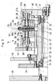
- Fig. 2 the transfer process or the transfer drum 14 shown in detail.
- the pivot arms 17a and 17b with respective Pot curve bodies 21a and 21b via cam rollers 22a and 22b are engaged.
- the curves 20a and 20b are substantially identical, so that a parallel Pivoting of the pivot arms 17a and 17b in one much of the movement of the transfer drum 14 given is.
- the Division of the alignment drum 15 shown.
- the pitch here is, for example, 6 ⁇ , whereas the pitch the transport drum 13, for example, 4 ⁇ is.
- the Division of the transfer drum 14 is on average 8 ⁇ .
- the Transfer drum rotates, for example, with about 210 revolutions / min.
- the cam rollers rotate, for example, with 1,600 Revolutions / min.
- the cam rollers 22a and 22b are in its center with the center of rotation of the pivot arms 17a and 17b connected by a lever arm 39.
- the transfer drum is shown in cross section.
- the hub 33 with Support 32 and the drive member 34 rotatably arranged.
- the connecting flange 35 connects concentrically two mirror-image interconnected drum body 36.
- the drum bodies 36 are concentric arranged at the same distance roller bearings Pivot arms 17a and 17b.
- lever arms 39 On the second wave end of the Swivel arms are lever arms 39 with cam rollers 22b for the cam follower at the front and 22a for the cam follower at the rear attached.
- cam tracks 20a and 20b in the Topfkurven stressesn 21a and 21b become the required Swivel movements of the swivel arms for product transfer and product handover initiated.
- the cam 21b is with an adjustable Topfkurvenarrettechnik 41 to Curved track 21a alignable.
- the required holding force for the transport is with Vacuum generated.
- suction air holes 18 are provided, the product or in this embodiment the filter plug 10a and 10b with the suction side a suitable blower connects.
- the suction air hole 42 or the air flow is with the help of Saug Kunststoff Kunststoff stresses 43 in the areas of product takeover and product delivery turned on or off.
- a corresponding control is known to the person skilled in the art.
- the cover 44 for the air box, the cover 45 for the Gearbox and the mounting plate 46 serve the Formation of a lubricant-tight drive housing and the external air duct.
- seals 47 provided, the suction air or the vacuum seal accordingly.
- the lever arms 39 are fastened by means of clamping screws 38.
- Fig. 4a shows a schematic side view of a Lever arm 39 with corresponding cam rollers 22a and 22b.
- FIG. 4b shows a plan view of the element of FIG. 4a, wherein it is indicated that the cam rollers 22a and 22b are arranged slightly offset axially. They are further Ball bearing 49 shown to the cam rollers 22a or 22b are rotatably mounted. It is also in both Fig. 4a and in Fig. 4b, the axis 48 shown.
Landscapes
- Manufacturing Of Cigar And Cigarette Tobacco (AREA)
- Cigarettes, Filters, And Manufacturing Of Filters (AREA)
- Specific Conveyance Elements (AREA)
- Manufacture Of Tobacco Products (AREA)
- Packaging Of Annular Or Rod-Shaped Articles, Wearing Apparel, Cassettes, Or The Like (AREA)
Abstract
Description
- Transportieren der Artikel in den Aufnahmen der ersten Transportvorrichtung in den Bereich einer ersten Übergabestation,
- Übergabe der Artikel in die Aufnahmen der Übertragungselemente, die sich im Bereich der ersten Übergabestation befinden,
- Transportieren der Artikel in den Bereich einer zweiten Übergabestation,
- Übergabe der Arikel in die Aufnahmen der zweiten Transportvorrichtung, wobei bei der Übergäbe der Artikel in der ersten Übergabestation jeweils wenigstens zwei axial fluchtend angeordnete Artikel in wenigstens zwei axial versetzt angeordnete Übertragungselemente übergeben werden, und daß zum Übergeben der Artikel an die zweite Transportvorrichtung die Aufnahmen der axial fluchtend angeordneten Übertragungselemente voneinander wegbewegt werden.
- Fig. 1
- eine schematische Draufsicht auf drei Trommeln sowie im rechten Bereich die relative Positionierung von entsprechenden Filterstöpseln,
- Fig. 2
- einen vergrößerten Ausschnitt aus der Fig. 1 in detaillierterer Darstellung,
- Fig. 3
- eine Querschnittsdarstellung durch eine erfindungsgemäße Staffeltrommel,
- Fig. 4a
- eine schematische Seitenansicht eines Hebelarms mit Kurvenrollen, und
- Fig. 4b
- eine schematische Draufsicht der Elemente aus Fig. 4a.
- 10
- Filterstöpsel
- 10a
- oberer Filterstöpsel
- 10b
- unterer Filterstöpsel
- 11
- Doppelfilterstöpsel
- 12
- Kreismesser
- 13
- Transporttrommel
- 14
- Übergabetrommel
- 15
- Ausrichttrommel
- 16
- Aufnahme
- 17a
- Schwenkarm oben
- 17b
- Schwenkarm unten
- 18
- Saugkanal
- 19
- Schnitt
- 20a
- Kurve vorne
- 20b
- Kurve hinten
- 21a
- Topfkurvenkörper vorne
- 21b
- Topfkurvenkörper hinten
- 22a
- Kurvenrolle vorne
- 22b
- Kurvenrolle hinten
- 25
- Teilung
- 26
- Fluchtungsvorrichtung
- 31
- Lagerbolzen
- 32
- Lagerung
- 33
- Nabe
- 34
- Antriebselement
- 35
- Verbindungsflansch
- 36
- Trommelkörper
- 37
- Lager
- 38
- Klemmschraube
- 39
- Hebelarm
- 40
- Ringspalt
- 41
- Topfkurvenarretierung
- 42
- Saugluftbohrung
- 43
- Saugluftsteuerkörper
- 44
- Deckel für Luftkasten
- 45
- Deckel für Getriebekasten
- 46
- Montageplatte
- 47
- Dichtung
- 48
- Achse
- 49
- Kugellager
- 50
- erste Ebene
- 51
- zweite Ebene
- 52
- erste Übergabestation
- 53
- zweite Übergabe station
- 54
- Drehrichtung
- a) bis l)
- relative Filterstöpselpositionen
Claims (20)
- Übertragungsvorrichtung zum Übertragen von Artikeln (10, 11) der tabakverarbeitenden Industrie von einer ersten Transportvorrichtung (13) zu einer zweiten Transportvorrichtung (15), wobei die Übertragungsvorrichtung verschwenkbare, mit jeweils einer Aufnahme (16) für einen Artikel (10, 11) versehene, in Umfangsrichtung hintereinander angeordnete Übertragungselemente (17a, 17b) umfaßt, dadurch gekennzeichnet, daß jeweils wenigstens zwei Übertragungselemente (17a, 17b) axial zueinander versetzt angeordnet sind.
- Übertragungsvorrichtung nach Anspruch 1, dadurch gekennzeichnet, daß die wenigstens zwei axial versetzt angeordneten Übertragungselemente (17a, 17b) unabhängig voneinander verschwenkbar sind.
- Übertragungsvorrichtung nach Anspruch 1 und/oder 2, dadurch gekennzeichnet, daß die jeweils axial versetzt liegenden Übertragungselemente (17a, 17b) Ebenen (50, 51) definieren, wobei je Ebene (50, 51) ein Kurvenkörper (21a, 21b) vorgesehen ist, mittels dem die Übertragungselemente (17a, 17b) einer dem jeweiligen Kurvenkörper (21a, 21b) zugeordneten Ebene (50, 51) verschwenkbar sind.
- Übertragungsvorrichtung nach einem oder mehreren der Ansprüche 1 bis 3, dadurch gekennzeichnet, daß diese eine drehbare Trommel (14) umfaßt.
- Übertragungsvorrichtung nach Anspruch 3 und/oder 4, dadurch gekennzeichnet, daß wenigstens ein Kurvenkörper (21a, 21b) derart ausgestaltet ist, daß bei einer Bewegung der Übertragungselemente (17a, 17b) hin zu einer ersten Übergabestation (52), bei der ein Aufnehmen von Artikeln (10, 11) durch Übertragungselemente (17a, 17b) der Übertragungsvorrichtung ermöglicht ist, die Übertragungselemente (17a, 17b) in Drehrichtung (54) oder in Richtung der ersten Übergabestation (52) verschwenkbar sind.
- Übertragungsvorrichtung nach Anspruch 5, dadurch gekennzeichnet, daß der wenigstens eine Kurvenkörper (21a, 21b) derart ausgestaltet ist, daß die Übertragungselemente (17a, 17b) während der Übergabe (52) entgegengesetzt zur Drehrichtung (54) verschwenkbar sind.
- Übertragungsvorrichtung nach einem oder mehreren der Ansprüche 3 bis 6, dadurch gekennzeichnet, daß die Kurvenkörper (21a, 21b) derart ausgestaltet sind, daß wenigstens teilweise eine asynchrone Bewegung der Übertragungselemente (17a, 17b) ermöglicht ist.
- Übertragungsvorrichtung nach Anspruch 7, dadurch gekennzeichnet, daß wenigstens ein Übertragungselement (17a, 17b) bei einer Bewegung hin zu einer zweiten Übergabestation (53), bei der eine Abgabe von Artikeln (10a, 10b) durch die Übertragungselemente (17a, 17b) ermöglicht ist, in Richtung der zweiten Übergabestation (53) verschwenkbar ist, so daß eine Staffelung der Artikel (10a, 10b) ermöglicht ist.
- Übertragungsvorrichtung nach einem oder mehreren der Ansprüche 5 bis 8, dadurch gekennzeichnet, daß die den Ebenen (50, 51) zugeordneten Kurvenkörper (21a, 21b) zumindest im Bereich der ersten Übergabestation (52) identisch geformt sind.
- Staffeleinrichtung zum Staffeln von stabförmigen Artikeln (10, 11) der tabakverarbeitenden Industrie, umfassend wenigstens eine erste Transportvorrichtung (13) mit Aufnahmen für jeweils wenigstens zwei axial fluchtende stabförmige Artikel und eine zweite Transportvorrichtung (15) mit Aufnahmen für jeweils einen stabförmigen Artikel, dadurch gekennzeichnet, daß eine Übertragungsvorrichtung (14) zwischen der ersten Transportvorrichtung (13) und der zweiten Transportvorrichtung (15) vorgesehen ist, mit Übertragungselementen (17a, 17b) zum Aufnehmen der wenigstens zwei axial fluchtenden Artikel (10, 10a, 10b) und zum gestaffelten Abgeben der Artikel (10a, 10b).
- Staffeleinrichtung nach Anspruch 10, dadurch gekennzeichnet, daß eine Fluchtungsvorrichtung (26) zum queraxialen Fluchten der in die zweite Transportvorrichtung (15) abgegebenen Artikel (10a, 10b) vorgesehen ist.
- Staffeleinrichtung nach Anspruch 10 und/oder 11,
dadurch gekennzeichnet, daß die Übertragungsvorrichtung (14) gem. einem oder mehreren der Ansprüche 1 bis 9 ausgebildet ist. - Maschine zur Herstellung von stabförmigen Produkten der tabakverarbeitenden Industrie mit wenigstens einer Übertragungsvorrichtung nach einem oder mehreren der Ansprüche 1 bis 9 und/oder mit wenigstens einer Staffeleinrichtung nach einem oder mehreren der Ansprüche 10 bis 12.
- Verwendung von mehreren in Umfangsrichtung einer Übertragungsvorrichtung hintereinander angeordneten Übertragungselementgruppen zum Übertragen von stabförmigen Artikeln (10, 11) der tabakverarbeitenden Industrie, wobei die Übertragungselementgruppen jeweils wenigstens zwei axial zueinander versetzt angeordnete verschwenkbare Übertragungselemente (17a, 17b) umfassen.
- Verwendung von Übertragungselementgruppen nach Anspruch 14, dadurch gekennzeichnet, daß die Übertragungselemente (17a, 17b) einer Gruppe unabhängig voneinander verschwenkbar sind.
- Verfahren zum Übertragen von stabförmigen Artikeln (10, 11) der tabakverarbeitenden Industrie von Aufnahmen (16) einer ersten Transportvorrichtung (13) zu Aufnahmen (16) einer zweiten Transportvorrichtung (15) unter Verwendung von Übertragungselementen (17a, 17b), die an einem Ende eine Aufnahme (16) aufweisen, mit den folgenden Verfahrensschritten:Transportieren der Artikel (10, 11) in den Aufnahmen (16) der ersten Transportvorrichtung (13) in den Bereich einer ersten Übergabestation (52),Übergabe der Artikel (10, 11) in die Aufnahmen (16) der Übertragungselemente (17a, 17b), die sich im Bereich der ersten Übergabestation (52) befinden,Transportieren der Artikel (10, 11) in den Bereich einer zweiten Übergabestation (53),Übergabe der Artikel (10, 11) in die Aufnahmen (16) der zweiten Transportvorrichtung (15), dadurch gekennzeichnet, daß bei der Übergabe der Artikel (10, 11) in der ersten Übergabestation (52) jeweils wenigstens zwei axial fluchtend angeordnete Artikel (10) in wenigstens zwei axial versetzt angeordnete Übertragungselemente (17a, 17b) übergeben werden, und daß zum Übergeben der Artikel (10) an die zweite Transportvorrichtung (15) die Aufnahmen (16) der axial fluchtend angeordneten Übertragungselemente (17a, 17b) voneinander wegbewegt werden.
- Verfahren nach Anspruch 16, dadurch gekennzeichnet, daß die voneinander wegbewegten Aufnahmen (10) auf einen Abstand voneinander wegbewegt werden, der im wesentlichen dem Teilungsabstand (25) der zweiten Trommel (15) entspricht.
- Verfahren nach Anspruch 16 und/oder 17, dadurch gekennzeichnet, daß die voneinander wegbewegten Aufnahmen (16) der Übertragungselemente (17a, 17b) beim Zuführen zur ersten Übergabestation (52) zueinander hinbewegt werden, bis diese miteinander fluchten.
- Verfahren nach einem oder mehreren der Ansprüche 16 bis 18, dadurch gekennzeichnet, daß die Artikel (10, 10a, 10b) in in Umfangsrichtung der zweiten Transportvorrichtung (15) benachbarte Aufnahmen (16) übergeben werden.
- Verfahren nach einem oder mehreren der Ansprüche 16 bis 19, dadurch gekennzeichnet, daß die in die zweite Transportvorrichtung (15) übergebenen Arikel (10, 10a, 10b) im folgenden queraxial gefluchtet werden.
Applications Claiming Priority (2)
| Application Number | Priority Date | Filing Date | Title |
|---|---|---|---|
| DE10141703A DE10141703A1 (de) | 2001-08-25 | 2001-08-25 | Übertragungsvorrichtung und Verfahren zum Übertragen von Artikeln der tabakverarbeitenden Industrie |
| DE10141703 | 2001-08-25 |
Publications (2)
| Publication Number | Publication Date |
|---|---|
| EP1287753A1 true EP1287753A1 (de) | 2003-03-05 |
| EP1287753B1 EP1287753B1 (de) | 2004-11-24 |
Family
ID=7696605
Family Applications (1)
| Application Number | Title | Priority Date | Filing Date |
|---|---|---|---|
| EP02013365A Expired - Lifetime EP1287753B1 (de) | 2001-08-25 | 2002-06-19 | Übertragungsvorrichtung und Verfahren zum Übertragen von Artikeln der tabakverarbeitenden Industrie |
Country Status (8)
| Country | Link |
|---|---|
| US (1) | US6736257B2 (de) |
| EP (1) | EP1287753B1 (de) |
| JP (1) | JP4084126B2 (de) |
| CN (1) | CN1247126C (de) |
| AT (1) | ATE282970T1 (de) |
| DE (2) | DE10141703A1 (de) |
| ES (1) | ES2231613T3 (de) |
| PL (1) | PL205682B1 (de) |
Cited By (10)
| Publication number | Priority date | Publication date | Assignee | Title |
|---|---|---|---|---|
| EP1588960A1 (de) * | 2004-04-22 | 2005-10-26 | G.D Societ Per Azioni | Übertragungseinheit für längliche Gegenstände |
| WO2006016246A1 (en) * | 2004-08-09 | 2006-02-16 | G.D S.P.A. | A method and a machine for making filter cigarettes |
| EP1679010A1 (de) * | 2005-01-06 | 2006-07-12 | Hauni Maschinenbau AG | Herstellung von Filterstopfen bzw. von Filterzigaretten |
| EP1733635A1 (de) * | 2005-06-14 | 2006-12-20 | Hauni Maschinenbau Aktiengesellschaft | Fördertrommel der Tabak verarbeitenden Industrie mit Hebelsegmenten |
| EP1787534A1 (de) * | 2005-11-16 | 2007-05-23 | G.D. Societa' per Azioni | Maschine zur Herstellung von Mehrfachfiltern |
| EP2294934A3 (de) * | 2009-09-15 | 2011-03-23 | HAUNI Maschinenbau AG | Einlegen von Filtersegmenten in Filterstränge |
| EP2335503A1 (de) * | 2009-12-16 | 2011-06-22 | HAUNI Maschinenbau AG | Multisegmentfilterherstellung der Tabak verarbeitenden Industrie |
| EP3047738A1 (de) * | 2015-01-20 | 2016-07-27 | Hauni Maschinenbau GmbH | Fördertrommel der tabak verarbeitenden industrie |
| EP2696708B1 (de) | 2011-04-14 | 2017-10-11 | Hauni Maschinenbau GmbH | Förderung von stabförmigen artikeln der tabak verarbeitenden industrie |
| DE102017121292A1 (de) | 2017-09-14 | 2019-03-14 | Hauni Maschinenbau Gmbh | Übertragungsvorrichtung der Tabak verarbeitenden Industrie |
Families Citing this family (12)
| Publication number | Priority date | Publication date | Assignee | Title |
|---|---|---|---|---|
| DE10245850A1 (de) * | 2002-09-30 | 2004-04-08 | Hauni Maschinenbau Ag | Fördern von Artikeln der tabakverarbeitenden Industrie |
| JP3739752B2 (ja) * | 2003-02-07 | 2006-01-25 | 株式会社 ハリーズ | ランダム周期変速可能な小片移載装置 |
| ATE327688T1 (de) * | 2003-04-11 | 2006-06-15 | Hauni Maschinenbau Ag | Verfahren zum vereinigen von rauchartikelkomponenten |
| DE102004025047A1 (de) * | 2004-05-18 | 2005-12-15 | Hauni Maschinenbau Ag | Herstellung von Filterstopfen bzw. von Filterzigaretten |
| DK1772403T3 (da) * | 2005-10-05 | 2008-08-18 | Fameccanica Data Spa | Apparat til at ændre den adskillende afstand mellem transporterede genstande |
| FR2907438B1 (fr) * | 2006-10-20 | 2009-01-16 | Sidel Participations | Procede et installation de changement de pas d'entites discretes convoyees les unes a la suite des autres |
| DE102011007091A1 (de) * | 2011-04-08 | 2012-10-11 | Hauni Maschinenbau Ag | Vorrichtung und Verfahren zum Bearbeiten von stabförmigen Artikeln der tabakverarbeitenden Industrie |
| PL222327B1 (pl) | 2012-07-12 | 2016-07-29 | Int Tobacco Machinery Poland Spółka Z Ograniczoną Odpowiedzialnością | Sposób i urządzenie do transferowania elementów prętopodobnych w maszynach przemysłu tytoniowego oraz maszyna do wytwarzania sztabek wieloelementowych |
| WO2015140742A1 (en) * | 2014-03-18 | 2015-09-24 | G.D Societa' Per Azioni | Method for producing smoking articles |
| DE102016125001A1 (de) * | 2016-12-20 | 2018-06-21 | Hauni Maschinenbau Gmbh | Rotationsfördervorrichtung zum Fördern von Artikeln der tabakverarbeitenden Industrie |
| PL244133B1 (pl) * | 2020-05-14 | 2023-12-04 | Int Tobacco Machinery Poland Spolka Z Ograniczona Odpowiedzialnoscia | Urządzenie do formowania końcówek artykułu prętopodobnego, urządzenie do produkcji artykułów prętopodobnych i sposób formowania końcówek artykułu prętoopdobnego dla przemysłu tytoniowego |
| CN119608474B (zh) * | 2025-02-13 | 2025-04-29 | 江苏安江汽车部件有限公司 | 汽车扰流板用喷涂生产系统 |
Citations (6)
| Publication number | Priority date | Publication date | Assignee | Title |
|---|---|---|---|---|
| US2944654A (en) * | 1958-07-25 | 1960-07-12 | Hauni Werke Koerber & Co Kg | Device for aligning filter rod portions in filter tip cigarette making machines |
| US3010561A (en) * | 1957-12-26 | 1961-11-28 | Koerber & Co Kg | Filter mouthpiece cigarette making machines |
| US3164243A (en) * | 1959-10-07 | 1965-01-05 | Hauni Werke Koerber & Co Kg | Method and apparatus for making filter plugs for filter tip cigarettes |
| US3887059A (en) * | 1973-01-04 | 1975-06-03 | Decoufle Usines | Device for aligning cylindrical articles |
| US4506779A (en) * | 1980-12-12 | 1985-03-26 | G.D. Societa Per Azioni | Device for transferring bar shaped articles |
| EP0679343A2 (de) * | 1994-03-31 | 1995-11-02 | Japan Tobacco Inc. | Trennvorrichtung für die Herstellung von Filtern für Zigaretten |
Family Cites Families (3)
| Publication number | Priority date | Publication date | Assignee | Title |
|---|---|---|---|---|
| DE3504555A1 (de) * | 1985-02-11 | 1986-10-30 | Jagenberg AG, 4000 Düsseldorf | Vorrichtung zum verteilen von gegenstaenden, insbesondere flaschen |
| US5769205A (en) * | 1994-10-13 | 1998-06-23 | G. D Societa Per Azioni | Continuous cigarette manufacturing machine |
| DE19540158C2 (de) * | 1995-10-27 | 1997-10-16 | Polytype Maschf Sa | Übergabevorrichtung |
-
2001
- 2001-08-25 DE DE10141703A patent/DE10141703A1/de not_active Withdrawn
-
2002
- 2002-06-19 DE DE50201389T patent/DE50201389D1/de not_active Expired - Lifetime
- 2002-06-19 EP EP02013365A patent/EP1287753B1/de not_active Expired - Lifetime
- 2002-06-19 ES ES02013365T patent/ES2231613T3/es not_active Expired - Lifetime
- 2002-06-19 AT AT02013365T patent/ATE282970T1/de not_active IP Right Cessation
- 2002-08-20 JP JP2002239285A patent/JP4084126B2/ja not_active Expired - Fee Related
- 2002-08-21 US US10/224,594 patent/US6736257B2/en not_active Expired - Fee Related
- 2002-08-22 PL PL355619A patent/PL205682B1/pl unknown
- 2002-08-23 CN CN02130190.5A patent/CN1247126C/zh not_active Expired - Fee Related
Patent Citations (6)
| Publication number | Priority date | Publication date | Assignee | Title |
|---|---|---|---|---|
| US3010561A (en) * | 1957-12-26 | 1961-11-28 | Koerber & Co Kg | Filter mouthpiece cigarette making machines |
| US2944654A (en) * | 1958-07-25 | 1960-07-12 | Hauni Werke Koerber & Co Kg | Device for aligning filter rod portions in filter tip cigarette making machines |
| US3164243A (en) * | 1959-10-07 | 1965-01-05 | Hauni Werke Koerber & Co Kg | Method and apparatus for making filter plugs for filter tip cigarettes |
| US3887059A (en) * | 1973-01-04 | 1975-06-03 | Decoufle Usines | Device for aligning cylindrical articles |
| US4506779A (en) * | 1980-12-12 | 1985-03-26 | G.D. Societa Per Azioni | Device for transferring bar shaped articles |
| EP0679343A2 (de) * | 1994-03-31 | 1995-11-02 | Japan Tobacco Inc. | Trennvorrichtung für die Herstellung von Filtern für Zigaretten |
Cited By (18)
| Publication number | Priority date | Publication date | Assignee | Title |
|---|---|---|---|---|
| CN100548162C (zh) * | 2004-04-22 | 2009-10-14 | 吉第联合股份公司 | 用于传递长条物品的传递单元 |
| EP1588960A1 (de) * | 2004-04-22 | 2005-10-26 | G.D Societ Per Azioni | Übertragungseinheit für längliche Gegenstände |
| US7530444B2 (en) | 2004-04-22 | 2009-05-12 | G.D Societa′ per Azioni | Transfer unit for transferring elongated articles |
| WO2006016246A1 (en) * | 2004-08-09 | 2006-02-16 | G.D S.P.A. | A method and a machine for making filter cigarettes |
| EP1679010A1 (de) * | 2005-01-06 | 2006-07-12 | Hauni Maschinenbau AG | Herstellung von Filterstopfen bzw. von Filterzigaretten |
| EP1733635A1 (de) * | 2005-06-14 | 2006-12-20 | Hauni Maschinenbau Aktiengesellschaft | Fördertrommel der Tabak verarbeitenden Industrie mit Hebelsegmenten |
| US7922638B2 (en) | 2005-11-16 | 2011-04-12 | G.D S.P.A. | Machine for manufacturing composite filters |
| EP1787534A1 (de) * | 2005-11-16 | 2007-05-23 | G.D. Societa' per Azioni | Maschine zur Herstellung von Mehrfachfiltern |
| CN1965709B (zh) * | 2005-11-16 | 2011-05-04 | 吉地股份公司 | 用于制造复合过滤嘴的机器 |
| EP2294934A3 (de) * | 2009-09-15 | 2011-03-23 | HAUNI Maschinenbau AG | Einlegen von Filtersegmenten in Filterstränge |
| EP2628399A1 (de) * | 2009-09-15 | 2013-08-21 | HAUNI Maschinenbau AG | Übergabetrommel der Tabak verarbeitenden Industrie |
| EP2335503A1 (de) * | 2009-12-16 | 2011-06-22 | HAUNI Maschinenbau AG | Multisegmentfilterherstellung der Tabak verarbeitenden Industrie |
| CN102100403A (zh) * | 2009-12-16 | 2011-06-22 | 豪尼机械制造股份公司 | 烟草加工业的多段过滤嘴制造 |
| EP2696708B1 (de) | 2011-04-14 | 2017-10-11 | Hauni Maschinenbau GmbH | Förderung von stabförmigen artikeln der tabak verarbeitenden industrie |
| EP2696708B2 (de) † | 2011-04-14 | 2022-12-28 | Körber Technologies GmbH | Förderung von stabförmigen artikeln der tabak verarbeitenden industrie |
| EP3047738A1 (de) * | 2015-01-20 | 2016-07-27 | Hauni Maschinenbau GmbH | Fördertrommel der tabak verarbeitenden industrie |
| DE102017121292A1 (de) | 2017-09-14 | 2019-03-14 | Hauni Maschinenbau Gmbh | Übertragungsvorrichtung der Tabak verarbeitenden Industrie |
| EP3456210A1 (de) * | 2017-09-14 | 2019-03-20 | Hauni Maschinenbau GmbH | Übertragungsvorrichtung der tabak verarbeitenden industrie |
Also Published As
| Publication number | Publication date |
|---|---|
| EP1287753B1 (de) | 2004-11-24 |
| CN1247126C (zh) | 2006-03-29 |
| US6736257B2 (en) | 2004-05-18 |
| PL355619A1 (en) | 2003-03-10 |
| ATE282970T1 (de) | 2004-12-15 |
| DE10141703A1 (de) | 2003-03-06 |
| CN1406529A (zh) | 2003-04-02 |
| JP2003070454A (ja) | 2003-03-11 |
| PL205682B1 (pl) | 2010-05-31 |
| ES2231613T3 (es) | 2005-05-16 |
| DE50201389D1 (de) | 2004-12-02 |
| JP4084126B2 (ja) | 2008-04-30 |
| US20030051978A1 (en) | 2003-03-20 |
Similar Documents
| Publication | Publication Date | Title |
|---|---|---|
| EP1287753B1 (de) | Übertragungsvorrichtung und Verfahren zum Übertragen von Artikeln der tabakverarbeitenden Industrie | |
| DE3137223C2 (de) | ||
| EP0770566B1 (de) | Übergabevorrichtung | |
| EP2251283B1 (de) | Fördervorrichtung mit Unterdruckansaugung | |
| DE2534666A1 (de) | Vorrichtung zum herstellen von kombinierten filterstopfen fuer filterzigaretten oder andere stabfoermige gegenstaende der tabakverarbeitenden industrie | |
| EP2364603A2 (de) | Tabakstrangmaschine zur Herstellung von Tabakstäben, Filteransetzmaschine zum Verbinden von Filtern mit Tabakstäben sowie Zigarettenherstellungsmaschine | |
| DE3641064A1 (de) | Foerdervorrichtung zum foerdern von einem doppelstrang abgetrennter stabfoermiger artikel der tabakverarbeitenden industrie | |
| EP1050222A1 (de) | Vorrichtung zum Wenden von stabförmigen Gegenständen | |
| DE2746915A1 (de) | Vorrichtung zum fuehren von werkzeugen an tabakverarbeitenden maschinen | |
| DE4203517A1 (de) | Vorrichtung zur ueberfuehrung von zigarettenabschnitten | |
| EP1164878B1 (de) | Vorrichtung zum transportieren von zigaretten oder dergleichen | |
| DE1481378B2 (de) | Vorrichtung zum Staffeln von queraxial geförderten Filterstopfen oder anderen stab förmigen Gegenstanden | |
| DE69617558T2 (de) | Verarbeitungsmaschine, insbesondere Verpackungsmaschine für Zigaretten oder dergleichen | |
| DE3445575C2 (de) | Vorrichtung zum Beabstanden und Umwenden von zwei koaxialen Zigarettenlängenabschnitten in einer Filterbestückungsmaschine | |
| EP1493338B1 (de) | Fördervorrichtung zum Überführen von stabförmigen Artikelen der Tabak verarbeitenden Industrie aus längsaxialer Förderung in queraxiale Weiterförderung | |
| DE69519958T4 (de) | Vorrichtung zum Ausrichten von stabförmigen Gegenständen | |
| EP3069619B1 (de) | Vorrichtung zum wenden von stabförmigen produkten der tabak verarbeitenden industrie um eine senkrecht zu einer längsachse der produkte ausgerichtete querachse | |
| DE102013104708B4 (de) | Vorrichtung zum Übergeben von stabförmigen Rauchartikeln | |
| EP3248477A1 (de) | Einlegevorrichtung und strangmaschine der tabak verarbeitenden industrie | |
| EP1827143B1 (de) | Einstosstrommel | |
| CH719848A1 (de) | Förderanlage mit einer Vorrichtung zum Lenken von liegend geförderten Fördergütern. | |
| DE3213393A1 (de) | Foerdervorrichtung fuer artikel der tabakverarbeitenden industrie | |
| EP3338567A1 (de) | Rotationsfördervorrichtung zum fördern von artikeln der tabakverarbeitenden industrie | |
| WO2022008220A1 (de) | Transfervorrichtung und verfahren zum übergeben stabförmiger artikel von einer strangbildenden vorrichtung an eine trommelvorrichtung | |
| DE2326181A1 (de) | Foerdereinrichtung zum foerdern stabfoermiger artikel |
Legal Events
| Date | Code | Title | Description |
|---|---|---|---|
| PUAI | Public reference made under article 153(3) epc to a published international application that has entered the european phase |
Free format text: ORIGINAL CODE: 0009012 |
|
| AK | Designated contracting states |
Kind code of ref document: A1 Designated state(s): AT BE CH CY DE DK ES FI FR GB GR IE IT LI LU MC NL PT SE TR Designated state(s): AT BE CH CY DE DK ES FI FR GB GR IE IT LI LU MC NL PT SE TR |
|
| AX | Request for extension of the european patent |
Extension state: AL LT LV MK RO SI |
|
| 17P | Request for examination filed |
Effective date: 20030428 |
|
| 17Q | First examination report despatched |
Effective date: 20030602 |
|
| AKX | Designation fees paid |
Designated state(s): AT BE CH CY DE DK ES FI FR GB GR IE IT LI LU MC NL PT SE TR |
|
| GRAP | Despatch of communication of intention to grant a patent |
Free format text: ORIGINAL CODE: EPIDOSNIGR1 |
|
| RIN1 | Information on inventor provided before grant (corrected) |
Inventor name: OESTERLING, ERWIN Inventor name: STEINIGER, WOLFGANG |
|
| GRAS | Grant fee paid |
Free format text: ORIGINAL CODE: EPIDOSNIGR3 |
|
| GRAA | (expected) grant |
Free format text: ORIGINAL CODE: 0009210 |
|
| PUAC | Information related to the publication of a b1 document modified or deleted |
Free format text: ORIGINAL CODE: 0009299EPPU |
|
| GRAA | (expected) grant |
Free format text: ORIGINAL CODE: 0009210 |
|
| AK | Designated contracting states |
Kind code of ref document: B1 Designated state(s): AT BE CH CY DE DK ES FI FR GB GR IE IT LI LU MC NL PT SE TR |
|
| REG | Reference to a national code |
Ref country code: GB Ref legal event code: FG4D Free format text: NOT ENGLISH |
|
| DB1 | Publication of patent cancelled | ||
| GBT | Gb: translation of ep patent filed (gb section 77(6)(a)/1977) |
Effective date: 20041027 |
|
| AK | Designated contracting states |
Kind code of ref document: B1 Designated state(s): AT BE CH CY DE DK ES FI FR GB GR IE IT LI LU MC NL PT SE TR |
|
| PG25 | Lapsed in a contracting state [announced via postgrant information from national office to epo] |
Ref country code: TR Free format text: LAPSE BECAUSE OF FAILURE TO SUBMIT A TRANSLATION OF THE DESCRIPTION OR TO PAY THE FEE WITHIN THE PRESCRIBED TIME-LIMIT Effective date: 20041124 Ref country code: IE Free format text: LAPSE BECAUSE OF FAILURE TO SUBMIT A TRANSLATION OF THE DESCRIPTION OR TO PAY THE FEE WITHIN THE PRESCRIBED TIME-LIMIT Effective date: 20041124 Ref country code: FI Free format text: LAPSE BECAUSE OF FAILURE TO SUBMIT A TRANSLATION OF THE DESCRIPTION OR TO PAY THE FEE WITHIN THE PRESCRIBED TIME-LIMIT Effective date: 20041124 |
|
| REG | Reference to a national code |
Ref country code: CH Ref legal event code: EP |
|
| REG | Reference to a national code |
Ref country code: IE Ref legal event code: FG4D Free format text: GERMAN |
|
| REF | Corresponds to: |
Ref document number: 50201389 Country of ref document: DE Date of ref document: 20041202 Kind code of ref document: P |
|
| GBT | Gb: translation of ep patent filed (gb section 77(6)(a)/1977) |
Effective date: 20041125 |
|
| REG | Reference to a national code |
Ref country code: GB Ref legal event code: ERR Free format text: THE ABOVE EP(UK) PATENT WAS ADVERTISED AS TRANSLATION FILED AND GRANTED ON 20041027 IN THE PATENTS AND DESIGNS JOURNAL NO. 6026 DATED 20041117 AS DESIGNATING THE UNITED KINGDOM AS A CONTRACTING STATE. HOWEVER THE ORIGINAL GRANT DATE HAS BEEN DELETED BY THE EPO AND A NEW GRANT DATE OF 20041124 HAS BEEN GIVEN. |
|
| PG25 | Lapsed in a contracting state [announced via postgrant information from national office to epo] |
Ref country code: SE Free format text: LAPSE BECAUSE OF FAILURE TO SUBMIT A TRANSLATION OF THE DESCRIPTION OR TO PAY THE FEE WITHIN THE PRESCRIBED TIME-LIMIT Effective date: 20050127 Ref country code: DK Free format text: LAPSE BECAUSE OF FAILURE TO SUBMIT A TRANSLATION OF THE DESCRIPTION OR TO PAY THE FEE WITHIN THE PRESCRIBED TIME-LIMIT Effective date: 20050127 |
|
| PG25 | Lapsed in a contracting state [announced via postgrant information from national office to epo] |
Ref country code: GR Free format text: LAPSE BECAUSE OF FAILURE TO SUBMIT A TRANSLATION OF THE DESCRIPTION OR TO PAY THE FEE WITHIN THE PRESCRIBED TIME-LIMIT Effective date: 20050224 |
|
| REG | Reference to a national code |
Ref country code: ES Ref legal event code: FG2A Ref document number: 2231613 Country of ref document: ES Kind code of ref document: T3 |
|
| PG25 | Lapsed in a contracting state [announced via postgrant information from national office to epo] |
Ref country code: LU Free format text: LAPSE BECAUSE OF NON-PAYMENT OF DUE FEES Effective date: 20050619 Ref country code: CY Free format text: LAPSE BECAUSE OF FAILURE TO SUBMIT A TRANSLATION OF THE DESCRIPTION OR TO PAY THE FEE WITHIN THE PRESCRIBED TIME-LIMIT Effective date: 20050619 Ref country code: AT Free format text: LAPSE BECAUSE OF NON-PAYMENT OF DUE FEES Effective date: 20050619 |
|
| REG | Reference to a national code |
Ref country code: IE Ref legal event code: FD4D |
|
| PG25 | Lapsed in a contracting state [announced via postgrant information from national office to epo] |
Ref country code: BE Free format text: LAPSE BECAUSE OF NON-PAYMENT OF DUE FEES Effective date: 20050630 Ref country code: MC Free format text: LAPSE BECAUSE OF NON-PAYMENT OF DUE FEES Effective date: 20050630 |
|
| ET | Fr: translation filed | ||
| PLBE | No opposition filed within time limit |
Free format text: ORIGINAL CODE: 0009261 |
|
| STAA | Information on the status of an ep patent application or granted ep patent |
Free format text: STATUS: NO OPPOSITION FILED WITHIN TIME LIMIT |
|
| 26N | No opposition filed |
Effective date: 20050825 |
|
| PGFP | Annual fee paid to national office [announced via postgrant information from national office to epo] |
Ref country code: ES Payment date: 20060605 Year of fee payment: 5 |
|
| PGFP | Annual fee paid to national office [announced via postgrant information from national office to epo] |
Ref country code: CH Payment date: 20060613 Year of fee payment: 5 |
|
| PGFP | Annual fee paid to national office [announced via postgrant information from national office to epo] |
Ref country code: FR Payment date: 20060629 Year of fee payment: 5 |
|
| PGFP | Annual fee paid to national office [announced via postgrant information from national office to epo] |
Ref country code: GB Payment date: 20060706 Year of fee payment: 5 |
|
| BERE | Be: lapsed |
Owner name: *HAUNI MASCHINENBAU A.G. Effective date: 20050630 |
|
| PG25 | Lapsed in a contracting state [announced via postgrant information from national office to epo] |
Ref country code: PT Free format text: LAPSE BECAUSE OF NON-PAYMENT OF DUE FEES Effective date: 20050424 |
|
| REG | Reference to a national code |
Ref country code: CH Ref legal event code: PL |
|
| GBPC | Gb: european patent ceased through non-payment of renewal fee |
Effective date: 20070619 |
|
| REG | Reference to a national code |
Ref country code: FR Ref legal event code: ST Effective date: 20080229 |
|
| PG25 | Lapsed in a contracting state [announced via postgrant information from national office to epo] |
Ref country code: LI Free format text: LAPSE BECAUSE OF NON-PAYMENT OF DUE FEES Effective date: 20070630 Ref country code: CH Free format text: LAPSE BECAUSE OF NON-PAYMENT OF DUE FEES Effective date: 20070630 |
|
| PG25 | Lapsed in a contracting state [announced via postgrant information from national office to epo] |
Ref country code: GB Free format text: LAPSE BECAUSE OF NON-PAYMENT OF DUE FEES Effective date: 20070619 |
|
| REG | Reference to a national code |
Ref country code: ES Ref legal event code: FD2A Effective date: 20070620 |
|
| PG25 | Lapsed in a contracting state [announced via postgrant information from national office to epo] |
Ref country code: FR Free format text: LAPSE BECAUSE OF NON-PAYMENT OF DUE FEES Effective date: 20070702 |
|
| PG25 | Lapsed in a contracting state [announced via postgrant information from national office to epo] |
Ref country code: ES Free format text: LAPSE BECAUSE OF NON-PAYMENT OF DUE FEES Effective date: 20070620 |
|
| REG | Reference to a national code |
Ref country code: DE Ref legal event code: R081 Ref document number: 50201389 Country of ref document: DE Owner name: HAUNI MASCHINENBAU GMBH, DE Free format text: FORMER OWNER: HAUNI MASCHINENBAU AG, 21033 HAMBURG, DE |
|
| REG | Reference to a national code |
Ref country code: NL Ref legal event code: PD Owner name: HAUNI MASCHINENBAU GMBH; DE Free format text: DETAILS ASSIGNMENT: VERANDERING VAN EIGENAAR(S), VERANDERING VAN DE JURIDISCHE ENTITEIT Effective date: 20160809 |
|
| PGFP | Annual fee paid to national office [announced via postgrant information from national office to epo] |
Ref country code: NL Payment date: 20190623 Year of fee payment: 18 |
|
| PGFP | Annual fee paid to national office [announced via postgrant information from national office to epo] |
Ref country code: DE Payment date: 20200701 Year of fee payment: 19 |
|
| PGFP | Annual fee paid to national office [announced via postgrant information from national office to epo] |
Ref country code: IT Payment date: 20200630 Year of fee payment: 19 |
|
| REG | Reference to a national code |
Ref country code: NL Ref legal event code: MM Effective date: 20200701 |
|
| PG25 | Lapsed in a contracting state [announced via postgrant information from national office to epo] |
Ref country code: NL Free format text: LAPSE BECAUSE OF NON-PAYMENT OF DUE FEES Effective date: 20200701 |
|
| REG | Reference to a national code |
Ref country code: DE Ref legal event code: R119 Ref document number: 50201389 Country of ref document: DE |
|
| PG25 | Lapsed in a contracting state [announced via postgrant information from national office to epo] |
Ref country code: DE Free format text: LAPSE BECAUSE OF NON-PAYMENT OF DUE FEES Effective date: 20220101 |
|
| PG25 | Lapsed in a contracting state [announced via postgrant information from national office to epo] |
Ref country code: IT Free format text: LAPSE BECAUSE OF NON-PAYMENT OF DUE FEES Effective date: 20210619 |
|
| REG | Reference to a national code |
Ref country code: CH Ref legal event code: PK Free format text: DIE ERTEILUNG VOM 27.10.2004 WURDE VOM EPA WIDERRUFEN. |