EP1286852B1 - Ameliorations apportees a un siege et procede de fabrication - Google Patents
Ameliorations apportees a un siege et procede de fabrication Download PDFInfo
- Publication number
- EP1286852B1 EP1286852B1 EP01935710A EP01935710A EP1286852B1 EP 1286852 B1 EP1286852 B1 EP 1286852B1 EP 01935710 A EP01935710 A EP 01935710A EP 01935710 A EP01935710 A EP 01935710A EP 1286852 B1 EP1286852 B1 EP 1286852B1
- Authority
- EP
- European Patent Office
- Prior art keywords
- seat back
- seat
- assembly
- seating assembly
- wall portion
- Prior art date
- Legal status (The legal status is an assumption and is not a legal conclusion. Google has not performed a legal analysis and makes no representation as to the accuracy of the status listed.)
- Expired - Lifetime
Links
Images


Classifications
-
- B—PERFORMING OPERATIONS; TRANSPORTING
- B60—VEHICLES IN GENERAL
- B60N—SEATS SPECIALLY ADAPTED FOR VEHICLES; VEHICLE PASSENGER ACCOMMODATION NOT OTHERWISE PROVIDED FOR
- B60N2/00—Seats specially adapted for vehicles; Arrangement or mounting of seats in vehicles
- B60N2/68—Seat frames
- B60N2/688—Particular seat belt attachment and guiding
-
- B—PERFORMING OPERATIONS; TRANSPORTING
- B29—WORKING OF PLASTICS; WORKING OF SUBSTANCES IN A PLASTIC STATE IN GENERAL
- B29C—SHAPING OR JOINING OF PLASTICS; SHAPING OF MATERIAL IN A PLASTIC STATE, NOT OTHERWISE PROVIDED FOR; AFTER-TREATMENT OF THE SHAPED PRODUCTS, e.g. REPAIRING
- B29C49/00—Blow-moulding, i.e. blowing a preform or parison to a desired shape within a mould; Apparatus therefor
- B29C49/42—Component parts, details or accessories; Auxiliary operations
- B29C49/48—Moulds
- B29C49/4802—Moulds with means for locally compressing part(s) of the parison in the main blowing cavity
-
- B—PERFORMING OPERATIONS; TRANSPORTING
- B60—VEHICLES IN GENERAL
- B60N—SEATS SPECIALLY ADAPTED FOR VEHICLES; VEHICLE PASSENGER ACCOMMODATION NOT OTHERWISE PROVIDED FOR
- B60N2/00—Seats specially adapted for vehicles; Arrangement or mounting of seats in vehicles
- B60N2/24—Seats specially adapted for vehicles; Arrangement or mounting of seats in vehicles for particular purposes or particular vehicles
- B60N2/32—Seats specially adapted for vehicles; Arrangement or mounting of seats in vehicles for particular purposes or particular vehicles convertible for other use
- B60N2/36—Seats specially adapted for vehicles; Arrangement or mounting of seats in vehicles for particular purposes or particular vehicles convertible for other use into a loading platform
- B60N2/366—Seats specially adapted for vehicles; Arrangement or mounting of seats in vehicles for particular purposes or particular vehicles convertible for other use into a loading platform characterised by the locking device
-
- B—PERFORMING OPERATIONS; TRANSPORTING
- B60—VEHICLES IN GENERAL
- B60N—SEATS SPECIALLY ADAPTED FOR VEHICLES; VEHICLE PASSENGER ACCOMMODATION NOT OTHERWISE PROVIDED FOR
- B60N2/00—Seats specially adapted for vehicles; Arrangement or mounting of seats in vehicles
- B60N2/68—Seat frames
- B60N2/682—Joining means
-
- B—PERFORMING OPERATIONS; TRANSPORTING
- B60—VEHICLES IN GENERAL
- B60N—SEATS SPECIALLY ADAPTED FOR VEHICLES; VEHICLE PASSENGER ACCOMMODATION NOT OTHERWISE PROVIDED FOR
- B60N2/00—Seats specially adapted for vehicles; Arrangement or mounting of seats in vehicles
- B60N2/68—Seat frames
- B60N2/686—Panel like structures
-
- B—PERFORMING OPERATIONS; TRANSPORTING
- B29—WORKING OF PLASTICS; WORKING OF SUBSTANCES IN A PLASTIC STATE IN GENERAL
- B29C—SHAPING OR JOINING OF PLASTICS; SHAPING OF MATERIAL IN A PLASTIC STATE, NOT OTHERWISE PROVIDED FOR; AFTER-TREATMENT OF THE SHAPED PRODUCTS, e.g. REPAIRING
- B29C49/00—Blow-moulding, i.e. blowing a preform or parison to a desired shape within a mould; Apparatus therefor
- B29C49/02—Combined blow-moulding and manufacture of the preform or the parison
- B29C49/04—Extrusion blow-moulding
-
- B—PERFORMING OPERATIONS; TRANSPORTING
- B29—WORKING OF PLASTICS; WORKING OF SUBSTANCES IN A PLASTIC STATE IN GENERAL
- B29C—SHAPING OR JOINING OF PLASTICS; SHAPING OF MATERIAL IN A PLASTIC STATE, NOT OTHERWISE PROVIDED FOR; AFTER-TREATMENT OF THE SHAPED PRODUCTS, e.g. REPAIRING
- B29C49/00—Blow-moulding, i.e. blowing a preform or parison to a desired shape within a mould; Apparatus therefor
- B29C49/42—Component parts, details or accessories; Auxiliary operations
- B29C49/48—Moulds
- B29C49/4802—Moulds with means for locally compressing part(s) of the parison in the main blowing cavity
- B29C49/4812—Moulds with means for locally compressing part(s) of the parison in the main blowing cavity and welding opposite wall parts of the parisons or preforms to each other
-
- B—PERFORMING OPERATIONS; TRANSPORTING
- B60—VEHICLES IN GENERAL
- B60N—SEATS SPECIALLY ADAPTED FOR VEHICLES; VEHICLE PASSENGER ACCOMMODATION NOT OTHERWISE PROVIDED FOR
- B60N2205/00—General mechanical or structural details
- B60N2205/30—Seat or seat parts characterised by comprising plural parts or pieces
- B60N2205/35—Seat, bench or back-rests being split laterally in two or more parts
-
- Y—GENERAL TAGGING OF NEW TECHNOLOGICAL DEVELOPMENTS; GENERAL TAGGING OF CROSS-SECTIONAL TECHNOLOGIES SPANNING OVER SEVERAL SECTIONS OF THE IPC; TECHNICAL SUBJECTS COVERED BY FORMER USPC CROSS-REFERENCE ART COLLECTIONS [XRACs] AND DIGESTS
- Y10—TECHNICAL SUBJECTS COVERED BY FORMER USPC
- Y10S—TECHNICAL SUBJECTS COVERED BY FORMER USPC CROSS-REFERENCE ART COLLECTIONS [XRACs] AND DIGESTS
- Y10S297/00—Chairs and seats
- Y10S297/02—Molded
Definitions
- the present invention relates to an improved seating system, and more particularly to an improved system for automotive vehicle seating.
- US-A-4142757 and US-A-4246734 both disclose a fold-down multi-purpose vehicle seatback core, which includes two parallel walls with tying links between them.
- US-A-5575533 discloses a blow molded vehicle seat frame system with an integral restraint safety belt. The molded frame contains tubular side cavities, housing reinforcing beams.
- US-A-5713634 discloses a seatback structure for a vehicle seat, utilising a blow-molded plastic seatback frame, with an anchor bracket preassembled integrally therein. The applicant has devised a seating assembly, including attachment assembly which provides significantly improved resistance to various forces, as is described in more detail herein after.
- the invention provides a seating assembly for an automotive vehicle, comprising a seat back formed from a molded plastic having a forward wall portion and a rearward wall portion, and a plurality of individual integrated reinforcement structures for defining an integrated reinforcement structure pattern; and an attachment assembly for anchoring said seat back to at least one body in white portion of said automotive vehicle; wherein the attachment assembly includes a channel-shaped member, affixed to both the forward wall portion and the rearward wall portion of the seat back, such that the seating assembly is capable of
- the present invention is premised upon the development of an improved automotive vehicle seat back assembly 10 having a molded plastic seat back 12 including a first wall portion 14 and an opposing second wall portion 16 (which wall portions may or may not be integrally formed) and one or more integrated reinforcement structures 18 disposed therebetween.
- a hinge assembly 20 is employed for pivotally anchoring the seat back 12 to an automotive vehicle.
- the hinge assembly 20 includes a receiving portion 22 for securing the seat back to said hinge assembly, and a mounting portion 24 for securing the hinge assembly to the vehicle.
- a retention mechanism 26 is employed for maintaining the seat back in a generally upright position.
- the hinge assembly 20, retention mechanism 26 or a combination of the two effectively define an assembly for attaching the seat back 12 to the vehicle and anchoring it to one or more body in white portions of the vehicle.
- the phrase “wall stock thickness” or “wall thickness” shall refer to the dimension (T w ) between a first surface 30 and a second surface 32 of a wall, such as first wall 34.
- the phrase “part section thickness” or “section thickness” (T s ) shall refer to the dimension between the first surface of the first wall and an outwardly disposed surface 36 of a second wall 38, if cut by an intersecting plane.
- integrated reinforcement structure shall refer to a location where, as shown in Fig. 2 the first wall 34 and second wall 38 of a molded component are joined, enlarged or reduced in wall thickness, section thickness, or otherwise configured to effectively create a beamed structural section for creating a locally modified bending moment or otherwise imparting additional rigidity, toughness or impact resistance to a seat back assembly.
- FIG. 2 various different structural configurations are shown, one or more of which can be employed in the design of seat backs for the present invention.
- One such configuration includes a tack-off 40, having a plurality of walls 42 (shown optionally in contact with the wall 38) that are spaced apart to effectively define a beam structure.
- Another illustrative configuration includes a tack-off 44 having a plurality of adjoining walls 46 in contact with each other.
- Yet another illustrative configuration includes a single wall rib 48, which can be formed, for instance, by employing one or a plurality of movable inserts in the tooling during forming.
- Still another configuration may include an enlarged rib 50 (i.e. having an enlarged portion on one or more of its sides) or some other like configuration.
- Another configuration includes a wall portion 52 that has a different wall thickness relative to an adjoining wall portion.
- the present invention contemplates the use of integrated reinforcement structures for imparting additional rigidity, toughness or impact resistance to a seat back assembly, or otherwise locally modifying the bending moment of a structure. While a variety of structures may be employed for this purpose, the most preferred structures are selected from ribs, tack-offs or a combination thereof.
- a seat back is fabricated by blow molding, pursuant to which a parison is placed in a cavity of a first tool adapted for defining the shape of a seat back.
- the parison is heated to a suitable temperature (e.g., for the preferred materials described hereinafter) from about 100°C to about 400°C, and more preferably about 225°C to about 300°C to induce plasticity.
- a gas is injected into the parison to cause expansion of the parison within the tool cavity and the formation of generally opposing spaced apart first and second wall portions.
- the first or optionally a second tool is brought into contact with one or both of the walls and deforms each contacted wall in the direction of the opposing wall.
- the opposing walls remain spaced from each other.
- the walls are brought into contact with each other and remain in contact by this deformation step, thereby forming a tack-off. It will be appreciated that the effect of forming each tack off is to form a structure having wall portions that project away (e.g., as ribs) from the wall portions from which they are formed.
- the section and wall profiles vary generally in at least one axis, e.g., in the z direction, to define individual integrated reinforcement structures.
- the section or wall profile might also vary in either or both of the x direction (i.e. cross car) or y direction (i.e. generally vertical in the seat's upright position) for an individual integrated reinforcement structure.
- the individual integrated reinforcement structures are made up of components that are vertically oriented (i.e. in the y-direction), horizontally oriented (i.e. in the x-direction), of a predetermined geometry, or a combination of some or all of these.
- a grouping of a plurality of individual integrated reinforcement structures constitutes an "integrated reinforcement structure pattern."
- a seat back 12 may include one or more patterns 54.
- FIG. 3 illustrates examples of various alternative predetermined geometric configurations for individual integrated reinforcement structures 18.
- FIG. 3 also illustrates examples of various integrated reinforcement structure patterns 54.
- the individual integrated reinforcement structure 18, and the integrated reinforcement structure pattern 54 may include one or a combination of any suitable letter, character, shape, or symbol. Examples of components of such structures or patterns include, without limitation, the "C” shape, "D” shape, "H” shape, “I” shape, “J” shape, “L” shape, “M” shape, “N” shape, “O” shape, "S” shape, “T” shape, “U” shape, "V” shape, "W” shape, "X” shape, "Y” shape, “Z” shape, curves (e.g.
- Integrated reinforcement structure patterns 54 include a plurality of individual integrated reinforcement structures 18. As seen in Fig. 3F and 3G, without limitation, the individual integrated reinforcement structure 18 may be a composite of multiple component shapes. The patterns 54 may be random, as seen in FIG.3B and 3G, or repetitious, as seen in FIGS. 3A or 3E. One or more different type of integrated reinforcement structures 18 of the type illustrated in FIG. 2 may be employed to define each pattern 54 used in a seat back 12.
- a vertically oriented integrated reinforcement structure requires openings to allow for air flow during molding, the location of the openings is preferably staggered to help reduce or eliminate hinge points.
- the horizontal spacing ("x" in FIG. 3A) between each individual integrated reinforcement structure will vary from about 5 mm to about 100 mm and more preferably about 20 mm to about 50 mm.
- One or more horizontally oriented integrated reinforcement structures might be incorporated in addition to or in lieu of vertical integrated reinforcement structures to help improve cross-car direction stiffness in a seat back.
- the horizontally oriented integrated reinforcement structures When employed with vertically oriented integrated reinforcement structures, the horizontally oriented integrated reinforcement structures preferably are staggered between vertically oriented integrated reinforcement structures or otherwise located to help reduce the likelihood they will serve as a hinge point. (See, e.g., FIG. 3G).
- Horizontally oriented integrated reinforcement structures may be added directly to existing vertically oriented integrated reinforcement structures (see, e.g., FIG. 3G and FIG. 3H).
- the horizontally oriented integrated reinforcement structures alternatively may be incorporated into an overall pattern so that the integrated reinforcement structure is angled or is substantially perpendicular to the horizontal bending diagonal plane.
- each integrated reinforcement structure 18 and pattern 54 fabricated in the seat back 12 may be optimized for each individual application, taking into account some or all of the following criteria.
- the specific integrated reinforcement structure employed is configured to help minimize the bending or hinge effect caused by loads resulting from rapid deceleration or acceleration of a vehicle in the presence of a passenger or cargo behind a seat (e.g., that which experienced by a top mounted center shoulder belt, top mounted child seat anchors, and luggage intrusion).
- the integrated reinforcement structure and pattern selected generally is one that will position a portion of the integrated reinforcement structure having a higher bending moment in a position generally perpendicular to the torsional bending diagonal plane.
- integrated reinforcement structures are further illustrated in the following discussion, by reference to two of the more commonly expected locations for integrated reinforcement structures, specifically in the perimeter regions of a seat back and in the regions proximate hardware, such as seat belts, seat belt anchors, hinges, latching components or the like.
- an integrated reinforcement structure around at least a portion of the perimeter 56 of the seat back 12 to help increase horizontal stiffness, vertical stiffness, or both in the perimeter regions of the seat back.
- an outboard edge 58 of the integrated reinforcement structure 18 is at or within about 50 mm (and more preferably about 15 mm) or less of an edge defining the perimeter 56 of the seat back 12.
- the width ("w") of any integrated reinforcement structure used in the perimeter regions of a seat back preferably ranges up to about 30mm, and more preferably it is about 4 to about 20 mm.
- tack-off 40 of FIG. 2 such dimension helps to minimize bending in the recessed valley portion 60.
- any latch strikers or latch members it is also preferable to form an integrated reinforcement structure in the vicinity of any latch strikers or latch members.
- FIG. 4 which shows an alternative hinge structure
- the bottom end 62 of a vertically oriented perimeter integrated reinforcement structure 64 will be positioned below the highest point 66 of a hinge assembly bracket 68 or other reinforcement 70 securing the seat back to the vehicle. More preferably, the overlap (“O") will range from about 25% to as high as about 100% of the vertical length (“L H ”) of any hinge or reinforcement.
- top end 72 of such vertical perimeter integrated reinforcement structure will be spaced from (e.g., within about 10 to about 200 mm of) the top of the seat.
- a thicker part section thickness as available by the use of structures 50 or 52 of FIGS. 1 and 2, may be incorporated at the top or bottom of the seat back to help increase stiffness.
- design criteria is employed to help reduce the forward, downward and torsional or diagonal bending of the seat back that are caused by perimeter loads at or adjacent the shoulder belt or tether attachments.
- the integrated reinforcement structures will provide good vertical stiffness (as this is the plane that is anticipated to endure the more severe bending forces), as well as good torsional stiffness (responsive to the diagonal offset loads a passenger imparts to a shoulder belt system).
- the integrated reinforcement structures it is preferable to alternate geometries of the integrated reinforcement structures either in a random or predetermined pattern, or to maintain the integrated reinforcement structure width up to about 40 mm, and more preferably up to about 30 mm (e.g., about 5 to about 30 mm).
- the employment of vertically oriented integrated reinforcement structures is particularly preferred in the load path for center belt loads and upper child seat tethers to help avoid vertical bending.
- the integrated reinforcement structure width (W) will vary up to about 50 mm and more preferably will be about 4 to about 40 mm, and still more preferably will be about 15 to about 25 mm.
- the vertically oriented integrated reinforcement structure length (L R ) will vary between about 70 to about 95% of the vertical seat back height, and more preferably about 80 to about 90%.
- the hinge assembly 20 of the present invention is provided in any suitable manner for assuring that the seat back remains anchored to the vehicle body in white in the event of a sudden or rapid acceleration, deceleration, or a large force is applied.
- hinge assemblies 20 are secured to the seat back 12 after fabrication of the seat back.
- the hinge assemblies 20 preferably include relatively tough and high strength to weight materials (such as plain carbon or alloy steels, or a comparable metal, composite or other material), and are configured for facilitating controlled deformation for transmitting loads.
- the hinge assembly 20 thus includes a bracket portion 74 adapted for receiving or otherwise engaging the seat back 12, and a suitable pivot portion 76, that can be secured to a vehicle body or other mounting surface, hingedly anchoring the overall seat back assembly 10.
- the hinge assembly 20 (and any other anchorage system) is connected to an anchoring substrate, preferably the vehicle body-in-white or an associated structure that has a breaking strength equal to or greater than the breaking strength of the webbing of any seat belt assembly installed as original equipment at that seating position.
- FIG. 1 illustrates one example of a manner for establishing a pivot attachment, in which a cross bar 78 is mounted to the vehicle body in white and carries the pivot portion and associated bracket portion. In Fig.
- bracket portion 80 adapted for mounting directly (or with an intermediate structure, such as seat track, pedestal, lower lock/latch, or the like) to the vehicle body in white.
- bracket portion 80 adapted for mounting directly (or with an intermediate structure, such as seat track, pedestal, lower lock/latch, or the like) to the vehicle body in white.
- a frame 82 having a cutout portion 84 is connected to define a seat halo assembly that may be connected to the vehicle body-in-white.
- the bracket portion 74 is adapted to receive the seat back in a nesting or mating type relationship, with the bracket portion acting as a female portion as generally shown in FIG. 4 and 5-7.
- bracket type includes a plurality of adjoining walls for defining a well or a generally "U-shaped" channel (with or without at least one closed end) for receiving and holding the seat back 12.
- the average wall thickness of the bracket assuming a high strength metal such as steel, will range from about 1 to about 3 mm.
- the bracket portion is an elongate member, having a length of about 30 to about 300 mm, and a width of about 10 to about 75 mm.
- the wall or walls can be disposed anywhere along the length of the hinge assembly (e.g., at one or both of its ends, or at an intermediate location).
- the walls may be configured in any suitable manner, with FIGS. 5 and 6 illustrating two such configurations.
- the walls include a first side wall portion 86 and a second opposing side wall portion 88, both of which are about the same length, and have an intermediate wall portion 90 bridging them.
- FIG. 5 the walls include a first side wall portion 86 and a second opposing side wall portion 88, both of which are about the same length, and have an intermediate wall portion 90 bridging them.
- a first side wall portion 92 and a second side wall portion 94 are joined with an intermediate portion 96.
- the first and second side portions are arranged so that a distal end 98 of the second side portion extends beyond a distal end 100 of the first side portion 92.
- the intermediate side portion 96 is such that it optionally includes a section terminating at an edge 102 that extends beyond the distal end 100 of the first side portion 92 toward the distal end 98 of the second side portion 94.
- the edge 102 may be any suitable configuration, e.g., linear, curved, stepped or the like, as shown in the illustrations of FIGS. 8A-8D. Further, though FIGS. 9A-9D illustrate a front to rear upward slope of the edge 102, the slope of the edge could be downward.
- the hinge assembly is secured to the seat back 12 using any suitable joining technique. It may be mechanically fastened (e.g., by screws or shoulder bolts), adhesively fastened, a combination thereof, or otherwise.
- a fastener 104 is secured through the first wall portion 14 and second wall portion 16 of the seat back and the hinge bracket 74.
- a fastener 104 is fastened to a stud that is formed in the hinge bracket 74 or otherwise placed between the opposing side wall portions.
- one possible bracket includes a side wall portion configured with a projection 106 for cooperating with an integrated reinforcing structure 18 and establishing an interference connection, thereby reinforcing the attachment in response to forward directed longitudinal forces (as illustrated in FIG. 7D).
- the bracket may be crimped into a tack off, or preformed to include a projection that penetrates the volume defined by the tack off, or otherwise grips an integrated reinforcement structure.
- the hinge assembly optionally may be further reinforced by the placement of a supplemental reinforcing insert 108 of suitable geometry (such as triangular, square, polygonal, rounded or otherwise) between or outside of the walls of the seat back, preferably in the vicinity of the bracket.
- a supplemental reinforcing insert 108 of suitable geometry (such as triangular, square, polygonal, rounded or otherwise) between or outside of the walls of the seat back, preferably in the vicinity of the bracket.
- the reinforcing insert 108 may be a steel (as with a hinge bracket)
- the reinforcing insert 108 preferably is made of a relatively tough and high strength to weight material, such as titanium, magnesium, aluminum, plastic, plastic composite, carbon fiber or the like.
- the supplemental reinforcement may be hollow or solid, and it may extend the entire span of the bracket or only a portion of it, or even beyond the bracket.
- the typical vertical length of one such reinforcement may range up to about 300 mm, with a cross car width of about 10 to about
- supplemental reinforcements is not limited to the regions adjacent the hinge assembly, but may be anywhere within the assembly.
- a relatively rigid member such as a metal (e.g., steel), composite, unfoamed plastic, or foamed plastic (either prefoamed or foamed in situ) may be incorporated between walls of a seat back wherever localized reinforcement is sought.
- suitable foams include polyurethanes, epoxies, styrenics, or the like. Softer foams may also be employed for noise and vibration absorption.
- the hinge assembly 20 will result in a portion of the seat back 12 that is susceptible to function as a deformation site or stress concentrator in the event of a sudden or rapid acceleration or deceleration of the vehicle.
- a deformation site or stress concentrator in the event of a sudden or rapid acceleration or deceleration of the vehicle.
- such anticipated deformation site is placed toward the wall that will be forward facing when assembled in the vehicle. For instance, it may be located along the leading edge of the seat back for inducing a compressive load in that region.
- brackets described above are particularly advantageously used in foldable seat applications such as found in rear seats of hatchback vehicles sedans or coupes. However, they may also be suitably employed in free standing seating assemblies, in which case they will be mounted to a pedestal or other structure associated with a seat track.
- the present systems may incorporate one or more retention mechanisms 26 (e.g., latch assemblies) at any of a number of different locations on the seat assembly (e.g., along the seat sides, on the seat back, or along the top of the seat back), for affording releasable self locking of the seat back to the vehicle relative to its hinge.
- any such retention mechanism provide a sufficient combination of high strength and good load distribution over the structure to which it is attached and high strength.
- the configuration is such that the seat is maintained in place by the retention mechanism in the event of a sudden or rapid acceleration, deceleration or other force, so that load on the seat back can be transferred as desired within the seat back.
- Retention mechanism configurations may vary from application to application. However, once engaged, for a forward-facing seat preferably such mechanism preferably will not release or fail when a forward longitudinal force (in Newton), equal to the product of 9.8 and 20 times the mass of the hinged or folding portion of the seat (kilograms), is applied approximately through the center of gravity of the latched seat portion. Moreover, once engaged, the mechanism preferably also will not release or fail when subjected to an acceleration of about 20 g., in the longitudinal direction opposite to the seat folding direction.
- a forward longitudinal force in Newton
- the mechanism preferably also will not release or fail when subjected to an acceleration of about 20 g., in the longitudinal direction opposite to the seat folding direction.
- a seatback configuration is illustrated with a pivotal mounting member.
- This configuration illustrates a seatback 12 with an extending pivot member 128.
- the extending pivot member 128 is configured such that the seatback 12 may be pivotally mounted to a bracket portion 80 thus negating the need for a cross bar 78.
- the maximum wall stock thickness will range up to about 6 mm or higher, more preferably it will range from about 1.5 mm to about 4.0 mm, and still more preferably, it will range from about 2.5 mm to about 3.5 mm.
- the maximum section thickness will range up to about 60 mm, more preferably it will range from about 20 mm to about 40 mm, and still more preferably it will range from about 25 to about 35 mm.
- the materials selected for forming the walls of the seat backs of the present invention preferably exhibit an elastic modulus ranging from about 500 MPa to about 6000 MPa, and more preferably about 1300 to about 1500 MPa, and still more preferably about 1700 to about 2500 MPa. In applications when the seat back is also to be used as a load bearing floor, it is preferable to select a material toward the higher end of the ranges.
- the preferred flexural modulus will be at least about 600 MPa, more preferably it will range from about 200 to about 500 ksi (1300 to about 3500 MPa), and still more preferably about 250 to about 350 ksi (1700 to about 2500 MPa).
- the preferred yield strength of the material ranges from about 20 to about 200 MPa. More preferably it will range from about 25 to about 70 MPa and still more preferably about 35 to about 55 MPa. Moreover, the ductility (as measured by percent elongation) of the material preferably ranges from about 20% to about 150%, and more preferably it is at least about 30% and still more preferably, it is at least about 100%.
- the material also will preferably exhibit attractive processing characteristics, such as a melt flow rate (230°C/3.8 kg-I; according to ASTM D1238) of about 0.300 to about 5.0 g/10 min to about 0.900 to about 3 g/10 min; a softening point (according to ASTM D1525) of less than about 180°C, and more preferably about 90°C to about 150°C; linear-flow mold shrink (according to ASTM D 955) of about 0.076 mm/mm (0.003 in/in) about 0.203 mm/mm (0.008 in/in) and more preferably about 0.152 mm/mm (0.006 in/in) to about 0.178 mm/mm (0.007 in/in); or a combination of these properties.
- a melt flow rate 230°C/3.8 kg-I
- ASTM D1238 a softening point
- linear-flow mold shrink accordinging to ASTM D 955) of about 0.076 mm/mm (0.003 in/in) about 0.203 mm/mm (0.008 in/in
- the seat back of the present invention preferably is made from a plastic material, and more preferably a thermoplastic material.
- the seat back is made from a high strength thermoplastic resin selected from styrenics, polyamides, polyolefins, polycarbonates, polyesters or mixtures thereof.
- acrylonitrile butadiene styrene polycarbonate/acrylonitrile/butadiene styrene, polycarbonate, polyphenylene oxide/polystyrene, polybutylene terephthalate, polybutylene terephthalate/polycarbonate, polyamide (e.g., nylon), polyesters, polypropylene, polyethylene, and mixtures thereof.
- Examples of preferred commercially available materials include PULSE® 2200 BG and MAGNUM® 1150 EM, both available from The Dow Chemical Company.
- blow molding While the technology of the present invention has been illustrated in connection with a blow molding fabrication process, it is not intended to be limited to such process. Like results may be attainable using the teachings of the present invention in combination with other fabrication techniques, including but not limited to injection molding, lost core processing, rotoforming, compression molding (with or without decorative or structural inserts), thermoforming, or the like. Preferably, when blow molding, the processing temperature will range.
- the seating system (1) is capable of withstanding without rupture at least 13 000 Newtons in the direction in which the seat faces in a plane, parallel to the longitudinal centerline of the vehicle; (2) exhibits, upon rapid acceleration up to at least 20 times "g" (the accelerator due to gravity), substantially no fragmentation of the seat back with at least a 30 kg mass placed behind the seat back; or (3) both (1) and (2).
- the seating system (1) is capable of withstanding without rupture at least about 13000 Newtons in the direction in which the seat faces in a plane, parallel to the longitudinal centerline of the vehicle; and (2) exhibits, upon rapid acceleration of times "g" (the accelerator due to gravity) 20, substantially no fragmentation of the seat back with at least a 36 kg mass placed behind the seat back;
- the seats, the anchorages, attachment hardware, and attachment bolts for the systems of the present invention are capable of withstanding without complete rupture at least a 3000 pound force and more preferably a 5,000 pound force.
- the system is capable of withstanding a force of at least about 13,000 N to about 22,000 N generally in the direction in which the seat faces (to a pelvic body block)in a plane parallel to the longitudinal centerline of the vehicle, with an initial force application angle of not less than about 5 degrees or more than about 15 degrees above the horizontal. Still more preferably, the system withstands such force even when applied at an onset rate of not more than about 133,000 N per second to about 222,000 N per second, whereby the force is attained in not more than about 30 seconds and is maintained for about 10 seconds.
- each seat assembly is capable of withstanding
- the seatback of the present invention is incorporated into a seat assembly, and two 18 kg masses (e.g., cubes with an edge length of about 300mm) are placed about 200 mm from the seat back. Upon rapid acceleration to at least about 20 to about 30 g, the seatback maintains the cargo disposed behind the seat back, with no visible fragmenting of the seat back or formation of sharp edges or corners.
- two 18 kg masses e.g., cubes with an edge length of about 300mm
- the seat backs made in accordance with the present invention are capable of exhibiting a set less than 6 mm after soaking for about 4 hours at about 82° C with an applied load of about 244 kg/m 2 and a momentary load of about 615 kg/m 2 .
- This seat back also will be greater than conventionally fabricated current blow molded polyethylene, filled polyethylene, polypropylene, or filled polypropylene seat backs.
- the present invention contemplates techniques and methods for the optimization of one or more of material selection, wall thickness, section thickness, hinge design, and latch design, for realizing the desired stiffness and strength to meet traditionally demanding load requirements in automotive vehicles occasioned of center mounted shoulder belt loads, child seat anchor loads, or cargo intrusion.
- material selection for the optimization of one or more of material selection, wall thickness, section thickness, hinge design, and latch design, for realizing the desired stiffness and strength to meet traditionally demanding load requirements in automotive vehicles occasioned of center mounted shoulder belt loads, child seat anchor loads, or cargo intrusion.
- design requirements will vary, and therefore a reasonable amount of experimentation may be needed to adapt the various teachings to the unique intended environment.
- part size, seat belt location, hinge points, latch locations, and split ratio may affect final design.
- CAE computer aided engineering
- the present invention finds useful application in connection with any of a number of different types of seating systems, including but not limited to, adjustable seats, fixed position seats, foldable seats, seats pivotal about an axis, including but not limited to hinged seats.
- the seats may be vehicle rear seats, vehicle front seats, jump seats or the like.
- Moveable seats may be held in place by latches disposed in the central portion of the seating configuration (e.g., at the top), along the seat sides (anywhere from the top to the bottom), or elsewhere.
- Fixed seats may include no latch assembly nor any assembly.
- the seating system may include one or more rear seats that fold downward to obtain a larger storage area, and which may require the seat back to act as load floor.
- the seat may be a split design (e.g., about 50/50, 60/40, 70/30 or the like), or the seats may constitute a one piece design.
- the seat back is latched to either a structural package shelf (top latches) or to the body in white (side outboard latches), and seat belt anchors or seat belt guidance system (as may be needed for a center mounted belt) for the two outboard seats is not attached on the seat. (See FIG. 1).
- a sliding lock pin might be incorporated between two folding seats.
- the sliding pin can be unlocked to fold down one portion of the seat and self locking when the seat backs are both upright.
- Localized reinforcement e.g., steel reinforcement or plastic foam
- Potential stress concentration locations such as hinge points, latch areas, seat belt anchorage locations, child seat tether anchor locations, head rest attachments, armrest support areas, or the like.
- seat belt anchors or a seat belt guidance system for the center seat belt and/or child tether anchors are attached to the seat.
- the top center seat belt mounting location is towards the middle of the seat back to help minimize the extent of cantilever, thereby helping to minimizing bending in response to a force.
- the present invention is particularly suitable for application in automotive vehicles of a number of different types, including but not limited to passenger cars (including sedans, coupes, station wagons, convertibles, or the like), multipurpose passenger vehicles (including sport utility vehicles, sport activity vehicles, minivans, or the like), trucks, and buses.
- passenger cars including sedans, coupes, station wagons, convertibles, or the like
- multipurpose passenger vehicles including sport utility vehicles, sport activity vehicles, minivans, or the like
- trucks and buses.
- Systems of the present invention are not limited to seat backs, but may also include one or more additional components for a vehicle interior system, particularly a seating system, such as seat belts, and seat belt anchorage components for transferring seat belt loads to the vehicle structure, including, but not limited to, the attachment hardware, seat frames, seat pedestals, the vehicle structure itself, and other parts of the vehicle that help to prevent of the belt from the vehicle structure.
- the systems may optionally include supplemental inflatable restraint systems, such as air bags.
- seating system components that are contemplated as within the systems of the present invention include, without limitation, seat adjusters (power actuated and manual), lumbar supports, child seats, child seat tether anchors, synthetic upholstery, natural upholstery (such as leather), seat warmers, seat coolers, headrests, integrated stereo components, arm rests, leg rests, cup holders, or the like.
- seat belt incorporated into the system is a shoulder belt, and more preferably a three point harness, other seat belt types may also be used, such as lap belts only, lap belts with a separate or detachable torso belt.
- a first wall could be moldably configured to provide a suitable lumbar support.
- An opposing wall i.e., the rearward facing wall when the seat back is in its upright position
- the opposing wall could be configured with suitable component housings or cargo carrying implements such as troughs, tie down members, tonneau cover brackets, seat belt retractor housings, or the like.
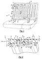
- Two seat back assemblies are fabricated for a sedan vehicle, such as the seat back assembly as shown generally in FIG. 12 having individual integrated reinforcement structures 18 defining an integrated reinforcement structure pattern 54 and an upper edge latch (not shown).
- One is fabricated using blow molded PULSE® 2200 BG resin (from The Dow Chemical Company).
- the other one is fabricated using blow molded MAGNUM® 1150 EM resin (from The Dow Chemical Company).
- a halo frame 82 carries the seat backs, which are hingedly connected along their bottom edge 130 and latched along the top edge 132.
- the seat back includes two child seat tether anchors 134, although other applications may include no anchor, a single anchor or more than one anchor, upper or lower.
- the final seat back has an average wall thickness in the seat back of about 3 mm, and an average section thickness of about 25 mm. Both assemblies pass United States and European government test standards for motor vehicles as addressed in FMVSS 207 (49 CFR 571.207), FMVSS 225 (49 CFR 571.225) and ECE 17, as well as the requirements of automobile original equipment manufacturers and their suppliers.
- Two seat back assemblies are fabricated for a vehicle with a rear hatch, such as seat back assembly as shown generally in FIG. 1.
- One is fabricated using blow molded PULSE® 2200 BG resin (from The Dow Chemical Company).
- the other one is fabricated using blow molded MAGNUM® 1150 EM resin (from The Dow Chemical Company).
- the final assembly has an average wall thickness in the seat back of about 3 mm, and an average section thickness of about 30 mm. Both assemblies pass United States and European government test standards for motor vehicles as addressed in FMVSS 207 (49 CFR 571.207), FMVSS 225 (49 CFR 571.225) and ECE 17, as well as the requirements of automobile original equipment manufacturers and their suppliers.
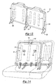
- Two seat back assemblies are fabricated for a vehicle to be a free-standing seat assembly, such as assembly as shown generally in FIG. 13 having individual integrated reinforcement structures 18 defining an integrated reinforcement structure pattern 54.
- the seat backs are secured to the vehicle body in white with a conventional lower lock/latch 136 connected to a bracket 138.
- One is fabricated using blow molded PULSE® 2200 BG resin (from The Dow Chemical Company).
- the other one is fabricated using blow molded MAGNUM® 1150 EM resin (from The Dow Chemical Company).
- the final assembly has an average wall thickness in the seat back of about 3 mm, and an average section thickness of about 30 mm. Both assemblies pass United States and European government test standards for motor vehicles as addressed in FMVSS 207 (49 CFR 571.207), FMVSS 225 (49 CFR 571.225) and ECE 17, as well as the requirements of automobile original equipment manufacturers and their suppliers.
- Two seat back assemblies are fabricated for a vehicle to have a center shoulder belt such as seat back assembly as shown generally in FIG. 14 having individual integrated reinforcement structures 18 defining an integrated reinforcement structure pattern 54 and a latch (not shown).
- One is fabricated, using blow molded PULSE® 2200 BG resin (from The Dow Chemical Company).
- the other one is fabricated using blow molded MAGNUM® 1150 EM resin (from The Dow Chemical Company).
- the seat back includes a housing 140 on one of its walls (illustrated optionally on the rear wall), for a seat belt retractor 142.
- the final assembly has an average wall thickness in the seat back of about 3 mm, and an average section thickness of about 30 mm.
- FMVSS 207 49 CFR 571.207
- FMVSS 210 49 CFR 571.210
- FMVSS 225 49 CFR 571.225
- ECE 17 the requirements of automobile original equipment manufacturers and their suppliers.
Abstract
Claims (10)
- Assemblage de siège pour véhicule automobile, comprenant un dossier (12) formé à partir d'une matière plastique moulée comportant une partie paroi avant (16) et une partie paroi arrière (14), et une pluralité de structures de renforcement intégrées individuelles (42, 46, 48, 50) pour définir un motif de structures de renforcement intégrées, et un ensemble de fixation pour attacher ledit dossier à au moins une partie de carrosserie brute dudit véhicule automobile ;
dans lequel l'ensemble de fixation comporte un élément en forme de rigole, fixé à la fois à la partie paroi avant (16) et à la partie paroi arrière (14) du dossier (12), de sorte que l'assemblage de siège est capable :(1) de supporter sans rupture au moins environ 13 000 newtons dans la direction dans laquelle le siège est tourné, dans un plan parallèle à l'axe longitudinal du véhicule ; et(2) lors d'une accélération rapide jusqu'à 20 à 30 "g" (accélération due à la gravité), de ne présenter substantiellement aucune fragmentation du dossier avec au moins une masse de 36 kg placée derrière le dossier. - Assemblage de siège selon la revendication 1, dans lequel le dossier est un dossier moulé par soufflage.
- Assemblage de siège selon la revendication 1 ou 2, comprenant en outre un mécanisme de retenue autobloquant et déverrouillable (26) pour maintenir ledit dossier dans une position globalement droite.
- Assemblage de siège selon l'une quelconque des revendications 1 à 3, dans lequel l'ensemble de fixation comprend :un assemblage d'articulation comportant une partie support incluant une partie première paroi latérale, une partie deuxième paroi latérale opposée et une paroi intermédiaire, lesdites parois étant contiguës les unes aux autres en définissant une rigole pour recevoir ledit dossier et un élément formant pivot (76) pour fixer de manière articulée ledit dossier directement sur une première partie de carrosserie brute dudit véhicule automobile ;une attache (112) fixée à une deuxième partie de carrosserie brute d'un véhicule automobile ; etun percuteur comportant un ergot d'entraínement saillant (118) attaché à une partie de montage (116) en prise à chevauchement avec ladite partie paroi arrière dudit siège (12) pour mettre en prise de façon coopérante ladite attache afin de maintenir ledit dossier dans une position globalement droite.
- Assemblage de siège selon l'une quelconque des revendications 1 à 4, dans lequel ledit dossier est formé à partir d'une matière plastique choisie parmi les polystyréniques, les polyamides, les polyoléfines, les polycarbonates et leurs mélanges.
- Assemblage de siège selon l'une quelconque des revendications 1 à 4, dans lequel ladite matière plastique moulée comprend un polyester-polycarbonate.
- Assemblage de siège selon l'une quelconque des revendications 1 à 6, dans lequel ledit assemblage de siège est adapté pour un siège de véhicule sur pied.
- Assemblage de siège selon l'une quelconque des revendications 1 à 7, dans lequel une pluralité desdites structures de renforcement intégrées individuelles inclut un bâtissage ayant une pluralité de parois.
- Assemblage de siège selon l'une quelconque des revendications 1 à 8, dans lequel une pluralité desdites structures de renforcement intégrées individuelles inclut au moins une nervure de paroi.
- Assemblage de siège selon l'une quelconque des revendications 1 à 9, comprenant en outre un insert de renforcement supplémentaire configuré pour être placé entre ladite partie paroi avant et ladite partie paroi arrière dudit dossier.
Applications Claiming Priority (7)
| Application Number | Priority Date | Filing Date | Title |
|---|---|---|---|
| US20869400P | 2000-06-01 | 2000-06-01 | |
| US208694P | 2000-06-01 | ||
| US24301200P | 2000-10-24 | 2000-10-24 | |
| US243012P | 2000-10-24 | ||
| US09/766,792 US6491346B1 (en) | 2000-06-01 | 2001-01-22 | Seating system and method for making the same |
| US766792 | 2001-01-22 | ||
| PCT/US2001/016266 WO2001092051A1 (fr) | 2000-06-01 | 2001-05-18 | Ameliorations apportées à un siège et procédé de fabrication |
Publications (2)
| Publication Number | Publication Date |
|---|---|
| EP1286852A1 EP1286852A1 (fr) | 2003-03-05 |
| EP1286852B1 true EP1286852B1 (fr) | 2005-08-31 |
Family
ID=27395241
Family Applications (1)
| Application Number | Title | Priority Date | Filing Date |
|---|---|---|---|
| EP01935710A Expired - Lifetime EP1286852B1 (fr) | 2000-06-01 | 2001-05-18 | Ameliorations apportees a un siege et procede de fabrication |
Country Status (8)
| Country | Link |
|---|---|
| US (4) | US6491346B1 (fr) |
| EP (1) | EP1286852B1 (fr) |
| AU (1) | AU2001261779A1 (fr) |
| CA (1) | CA2410261C (fr) |
| DE (1) | DE60113102T2 (fr) |
| ES (1) | ES2244620T3 (fr) |
| MX (1) | MXPA02011856A (fr) |
| WO (1) | WO2001092051A1 (fr) |
Cited By (3)
| Publication number | Priority date | Publication date | Assignee | Title |
|---|---|---|---|---|
| US8511748B2 (en) | 2008-05-28 | 2013-08-20 | Styron Europe Gmbh | Vehicular seat back assembly |
| US8998316B2 (en) | 2010-06-07 | 2015-04-07 | Styron Europe Gmbh | Seating assembly with a blow molded seat back |
| EP2663445B1 (fr) | 2011-01-12 | 2016-08-10 | Salflex Polymers Limited | Objet creux doté d'éléments structuraux moulé par soufflage et procédé de moulage par soufflage |
Families Citing this family (111)
| Publication number | Priority date | Publication date | Assignee | Title |
|---|---|---|---|---|
| US7040696B2 (en) * | 1998-10-30 | 2006-05-09 | Indiana Mills & Manufacturing, Inc. | System of seats for a vehicle |
| US6886889B2 (en) * | 1998-10-30 | 2005-05-03 | Indiana Mills & Manufacturing, Inc. | Restraint system for a vehicle |
| US6491346B1 (en) | 2000-06-01 | 2002-12-10 | Dow Global Technologies, Inc. | Seating system and method for making the same |
| DE10126014C1 (de) * | 2001-05-28 | 2003-01-09 | Porsche Ag | Klappbare Rückenlehne für einen Rücksitz eines Kraftfahrzeugs |
| US6739673B2 (en) * | 2001-08-15 | 2004-05-25 | Dow Global Technologies, Inc. | Seating system |
| DE10142981B4 (de) * | 2001-09-01 | 2005-04-21 | Keiper Gmbh & Co. Kg | Lehnenpolsterträger für einen Fahrzeugsitz |
| US6786551B2 (en) * | 2001-10-08 | 2004-09-07 | Lear Corporation | Seat latching assembly |
| US6669259B2 (en) * | 2001-11-09 | 2003-12-30 | Pro-Gard Industries, L.P. | Vehicle partition |
| US6783184B2 (en) * | 2002-01-17 | 2004-08-31 | Bayer Polymers Llc | Molded article having a rigid support and a flexible hollow member |
| US7144085B2 (en) * | 2002-03-05 | 2006-12-05 | Indiana Mills & Manufacturing, Inc. | Passenger restraint system |
| US6896324B1 (en) * | 2002-04-19 | 2005-05-24 | Adam Aircraft Industries | Hybrid composite-metal energy absorbing seat |
| US7128373B2 (en) * | 2002-09-27 | 2006-10-31 | Dow Global Technologies, Inc. | Seating system and method of forming same |
| DE10250218A1 (de) * | 2002-10-23 | 2004-05-06 | Volkswagen Ag | Gewichtsoptimierte Rückenlehne für einen Kraftfahrzeugsitz |
| US7250091B2 (en) * | 2003-02-13 | 2007-07-31 | Dow Global Technologies Inc | Method of forming a seating system |
| FR2856351B1 (fr) * | 2003-06-20 | 2005-10-28 | Faurecia Sieges Automobile | Armature de dossier de siege de vehicule automobile, et procede de realisation d'une telle armature |
| US7383911B2 (en) * | 2003-09-19 | 2008-06-10 | Ford Global Technologies Llc | Wireless seatbelt buckle switch harvesting energy and method therefor |
| US7536973B2 (en) * | 2005-01-07 | 2009-05-26 | Plastic Safety Systems, Inc. | Plastic blow molded board-like members |
| FR2868023B1 (fr) * | 2004-03-26 | 2006-06-02 | Faurecia Sieges Automobile | Dossier de siege de vehicule adapte pour permettre la fixation d'un siege pour enfant et siege de vehicule comprenant un tel dossier |
| KR100733134B1 (ko) * | 2005-04-29 | 2007-06-28 | 주식회사 엘지화학 | 프레임 패널 |
| DE102005028929B4 (de) * | 2005-06-22 | 2009-04-09 | Wilhelm Karmann Gmbh | Bauteilgruppe für ein Cabriolet-Kraftfahrzeug |
| US7980589B2 (en) * | 2005-11-17 | 2011-07-19 | Salflex Polymers Ltd. | Inflatable bolster |
| US8128174B2 (en) | 2006-01-31 | 2012-03-06 | Lear Corporation | Pocketed molded vehicle backrest |
| US7585027B2 (en) | 2006-04-07 | 2009-09-08 | Schukra Of North America | Overmolded thin-profile lumbar support |
| EP1857321A2 (fr) * | 2006-05-18 | 2007-11-21 | Nissan Motor Co., Ltd. | Structure de siège |
| US7775603B2 (en) * | 2006-06-29 | 2010-08-17 | L & P Property Management Company | Seat suspension system and seat cushion module holder |
| EP2046601A2 (fr) * | 2006-07-21 | 2009-04-15 | Basf Se | Ensemble dossiers de sièges modulaires |
| DE102006038785A1 (de) * | 2006-08-18 | 2008-02-21 | Johnson Controls Gmbh | Metallstruktur für die Innenausstattung eines Kraftfahrzeuges |
| US7497521B2 (en) * | 2006-08-30 | 2009-03-03 | Honda Motor Co., Ltd | Seat belt retractor mounting system |
| US7887668B2 (en) * | 2006-08-30 | 2011-02-15 | Dow Global Technologies Inc. | Amine organoborane polymerizable compostion and uses therefor |
| DE102006046877B4 (de) * | 2006-10-04 | 2021-08-05 | Volkswagen Ag | Montierbare Schottwand zwischen Fahrgastraum und Kofferraum |
| JP4682963B2 (ja) * | 2006-10-26 | 2011-05-11 | 日産自動車株式会社 | 車両用シートバックのフレーム構造 |
| US20080145635A1 (en) * | 2006-12-15 | 2008-06-19 | General Electric Company | Automotive interior structural components with integral close-out panel |
| US7842146B2 (en) | 2007-01-26 | 2010-11-30 | Dow Global Technologies Inc. | Ultrasonic energy for adhesive bonding |
| US20080211275A1 (en) * | 2007-03-02 | 2008-09-04 | M2K, Llc. | Seat assembly for a vehicle and a method of manufacturing the same |
| WO2008121754A1 (fr) * | 2007-03-30 | 2008-10-09 | Dow Global Technologies, Inc. | Système de siège de véhicule renforcé de mousse |
| US7854479B2 (en) * | 2007-04-30 | 2010-12-21 | L&P Property Management Company | Overmolded lumbar support apparatus and method |
| US20080277976A1 (en) * | 2007-05-10 | 2008-11-13 | M&C Corporation | Seat back assist |
| DE102007053964A1 (de) * | 2007-07-18 | 2009-01-22 | Johnson Controls Gmbh | Struktur für einen Fahrzeugsitz |
| DE102007053962A1 (de) | 2007-07-18 | 2009-01-22 | Johnson Controls Gmbh | Struktur für Fahrzeugsitz |
| DE102007041222A1 (de) * | 2007-08-31 | 2009-03-05 | Lear Corp., Southfield | Fahrzeugsitz-Verbundrahmen |
| DE102008036646A1 (de) * | 2007-10-26 | 2009-04-30 | C. Rob. Hammerstein Gmbh & Co. Kg | Rahmenseitenteil eines Fahrzeugsitzes |
| US7753435B2 (en) * | 2007-11-26 | 2010-07-13 | Chrysler Group Llc | Water shield for vehicle door |
| US20090184562A1 (en) * | 2008-01-18 | 2009-07-23 | International Truck Intellectual Property Company, Llc | School bus seat frame back attachment |
| US20090189321A1 (en) | 2008-01-29 | 2009-07-30 | Dow Global Technologies Inc. | Thermoplastic composition and use for large parison blow molding applications |
| DE102008020290B4 (de) * | 2008-04-22 | 2015-02-19 | Johnson Controls Gmbh | Strukturteil und Fahrzeugsitz mit einer Rückenlehne |
| FR2930476B1 (fr) * | 2008-04-25 | 2013-08-30 | Rehau Sa | Piece plane en matiere plastique soufflee ou injectee, a rigidite amelioree |
| FR2931113B1 (fr) | 2008-05-16 | 2010-08-13 | Rehau Sa | Corps de dossier de siege rabattable pour vehicule |
| KR20110011701A (ko) * | 2008-05-23 | 2011-02-08 | 다우 글로벌 테크놀로지스 인크. | 개선된 차량 좌석 시스템 |
| JP5408688B2 (ja) * | 2008-05-28 | 2014-02-05 | 株式会社デルタツーリング | シート |
| CN102056764B (zh) * | 2008-06-06 | 2013-09-25 | 日产自动车株式会社 | 折叠式座椅 |
| US8414053B2 (en) | 2008-12-19 | 2013-04-09 | Toyota Motor Engineering & Manufacturing North America, Inc. | Seat back assembly with integral reinforcement structure |
| US7959233B2 (en) * | 2008-12-19 | 2011-06-14 | Toyota Motor Engineering & Manufacturing North America, Inc. | Seat back assembly with integral reinforcement structure |
| US7954899B2 (en) * | 2008-12-22 | 2011-06-07 | Toyota Motor Engineering & Manufacturing North America, Inc. | Seat back assembly with an adjustable headrest |
| US8157322B2 (en) * | 2008-12-22 | 2012-04-17 | Toyota Motor Engineering & Manufacturing North America, Inc. | Seat back assembly with low density frame |
| NL2002430C2 (en) * | 2009-01-19 | 2010-07-20 | Bonne Mechanisatie B V D | Improved car seat. |
| DE102009012772A1 (de) * | 2009-03-13 | 2010-09-16 | Koki Technik Seating Systems Gmbh | Fahrzeugsitz |
| DE102009012782B4 (de) * | 2009-03-13 | 2014-02-27 | Kokinetics Gmbh | Fahrzeugsitz |
| US8864239B2 (en) * | 2009-07-10 | 2014-10-21 | Johnson Controls Technology Company | Vehicle seat back rest structure |
| US9254770B2 (en) | 2009-09-22 | 2016-02-09 | Johnson Controls Gmbh | Method for producing a rear wall of a seat backrest |
| DE102009050840A1 (de) * | 2009-10-20 | 2011-06-09 | Keiper Gmbh & Co. Kg | Lehnenschlossanbindung für eine Rückenlehne einer Rücksitzanlage eines Kraftfahrzeugs |
| DE102009050839B4 (de) | 2009-10-20 | 2022-03-03 | Adient Luxembourg Holding S.À R.L. | Rückenlehne, insbesondere für eine Rücksitzanlage eines Kraftfahrzeugs |
| JP5511310B2 (ja) * | 2009-10-27 | 2014-06-04 | 日本発條株式会社 | 車両用シート |
| FR2952593B1 (fr) * | 2009-11-13 | 2011-10-28 | Rehau Sa | Procede de rigidification d'un corps de dossier de siege, en matiere plastique soufflee |
| US8042855B2 (en) * | 2009-11-24 | 2011-10-25 | Honda Motor Co., Ltd. | Lateral slide vehicle seat |
| IT1399531B1 (it) * | 2010-04-09 | 2013-04-19 | Arper Spa | Elemento di seduta |
| DE102010016775B3 (de) * | 2010-05-04 | 2011-11-17 | MöllerTech GmbH | Verfahren zum Herstellen eines Sitzbauteils mit einer Kopfstützenaufnahme und Sitzbauteil |
| FR2959702B1 (fr) * | 2010-05-07 | 2012-05-18 | Rehau Sa | Corps de dossier de siege en plastique souffle, comportant un dispositif d'ancrage pour la fixation securisee d'un siege enfant. |
| DE102010024715A1 (de) * | 2010-06-23 | 2011-12-29 | Volkswagen Ag | Rückenlehne eines Kraftfahrzeugsitzes |
| EP2412571B1 (fr) * | 2010-07-28 | 2020-04-15 | Adient Luxembourg Holding S.à r.l. | Dossier rabattable pour siège de véhicule et procédé de fabrication d'un dossier rabattable pour siège de véhicule |
| DE102010036798B4 (de) * | 2010-08-02 | 2022-09-29 | Kokinetics Gmbh | Sitzteil |
| DE102010039361A1 (de) * | 2010-08-16 | 2012-02-16 | Brose Fahrzeugteile Gmbh & Co. Kommanditgesellschaft, Coburg | Fahrzeugsitz mit mehreren Beschlägen |
| JP5189146B2 (ja) * | 2010-08-26 | 2013-04-24 | トヨタ紡織株式会社 | 車両用シート |
| WO2012075297A1 (fr) * | 2010-12-01 | 2012-06-07 | Salflex Polymers Limited | Dossier ayant une barre d'ancrage |
| DE202011000563U1 (de) | 2011-03-11 | 2011-05-12 | MöllerTech GmbH | Sitzlehnenbauteil und Sitzlehnensystem |
| JP2012254686A (ja) | 2011-06-08 | 2012-12-27 | Toyota Boshoku Corp | 車両用シート |
| JP5799097B2 (ja) * | 2011-07-05 | 2015-10-21 | 日本発條株式会社 | 車両シート用締結構造 |
| EP2546098B1 (fr) * | 2011-07-13 | 2015-07-08 | C.R.F. Società Consortile per Azioni | Procédé pour fabriquer différents dossiers pour sièges arrière de véhicule à moteur et ensemble de dossiers produit selon ce procédé |
| US8851569B2 (en) * | 2011-09-23 | 2014-10-07 | Chang-Hsien Ho | Full-cover and light-weight safety seat for child |
| DE102011056430A1 (de) * | 2011-12-14 | 2013-06-20 | Dr. Ing. H.C. F. Porsche Ag | Kraftfahrzeugsitz |
| US8746772B2 (en) * | 2011-12-20 | 2014-06-10 | Honda Motor Co., Ltd. | Seating assembly for a vehicle |
| DE102012207118A1 (de) * | 2012-04-27 | 2013-10-31 | Bayerische Motoren Werke Aktiengesellschaft | Bauteil aus Kunststoff |
| DE102012009505A1 (de) * | 2012-05-14 | 2013-11-14 | Johnson Controls Gmbh | Bauteilanordnung, fahrzeugsitz und herstellungsverfahren |
| DE102012214039A1 (de) * | 2012-05-29 | 2013-12-05 | Keiper Gmbh & Co. Kg | Lehnenteil für einen Sitz, insbesondere einen Fahrzeugsitz |
| JP5961453B2 (ja) * | 2012-06-11 | 2016-08-02 | 日本発條株式会社 | 車両用シート |
| DE102012018261A1 (de) * | 2012-09-17 | 2014-03-20 | GM Global Technology Operations, LLC (n.d. Ges. d. Staates Delaware) | Schwenkgelenkanordnung für einen Fahrzeugsitz und Fahrzeugsitz mit der Schwenkgelenkanordnung |
| USD697726S1 (en) | 2012-09-20 | 2014-01-21 | Steelcase Inc. | Chair |
| US11304528B2 (en) | 2012-09-20 | 2022-04-19 | Steelcase Inc. | Chair assembly with upholstery covering |
| DE102013003787B4 (de) * | 2012-11-30 | 2022-09-08 | Adient Us Llc | Fahrzeugsitz |
| US9004606B2 (en) | 2013-04-17 | 2015-04-14 | H.O. Bostrom Company, Inc. | Emergency vehicle seat with integrated seat belt and height adjustable webbing guide |
| DE102013012291A1 (de) * | 2013-07-24 | 2015-01-29 | Man Truck & Bus Ag | Fahrzeugsitz, insbesondere Fahrgastsitz für einen Bus |
| JP5915603B2 (ja) * | 2013-08-29 | 2016-05-11 | トヨタ自動車株式会社 | シートバックフレーム構造 |
| DE102013021692A1 (de) * | 2013-12-19 | 2015-06-25 | GM Global Technology Operations LLC (n. d. Ges. d. Staates Delaware) | Kraftfahrzeugsitzelement |
| DE102013021864A1 (de) | 2013-12-20 | 2015-06-25 | GM Global Technology Operations LLC (n. d. Ges. d. Staates Delaware) | Fahrzeugsitzbank für ein Kraftfahrzeug |
| JP6181563B2 (ja) * | 2014-01-22 | 2017-08-16 | テイ・エス テック株式会社 | 乗物用シート |
| JP6256121B2 (ja) * | 2014-03-12 | 2018-01-10 | スズキ株式会社 | 車両用シート構造 |
| CN104494472A (zh) * | 2014-05-28 | 2015-04-08 | 苏州雷姆斯汽车工程有限公司 | 一种碳纤维加强安全座椅基体 |
| JP6387258B2 (ja) * | 2014-07-10 | 2018-09-05 | 日本発條株式会社 | シートバックフレーム及び車両用シート |
| US9616779B2 (en) * | 2014-10-20 | 2017-04-11 | Lear Corporation | Seat assembly having a latch mechanism |
| WO2017058760A1 (fr) * | 2015-10-02 | 2017-04-06 | Johnson Controls Technology Company | Structure de siège automobile en plastique moulé par soufflage |
| CN108601451B (zh) | 2016-02-12 | 2021-07-06 | 安道拓卢森堡控股有限公司 | 座椅靠背框架 |
| JP6680089B2 (ja) * | 2016-06-07 | 2020-04-15 | スズキ株式会社 | 車両用シートバック組立体 |
| JP6780404B2 (ja) * | 2016-09-21 | 2020-11-04 | トヨタ紡織株式会社 | 乗物用シート |
| JP6828338B2 (ja) * | 2016-09-21 | 2021-02-10 | トヨタ紡織株式会社 | 乗物用シート |
| US10308203B2 (en) * | 2017-06-20 | 2019-06-04 | Ford Global Technologies, Llc | Stab proof back panel for law enforcement vehicle |
| US11685303B2 (en) | 2018-08-31 | 2023-06-27 | Daniel R. Brettschneider | Berth apparatus and methods using physiological parameters for controlling berth motion to promote relaxation and to induce sleep |
| EP3847053B1 (fr) | 2018-09-04 | 2023-10-25 | Safran Seats USA LLC | Dossier métallique léger avec espace vital supplémentaire |
| EP3643563A1 (fr) * | 2018-10-24 | 2020-04-29 | Volvo Car Corporation | Structure de cadre pour dossier de siège de véhicule |
| US10681983B2 (en) * | 2018-11-15 | 2020-06-16 | Series International, Llc | Beam seating system |
| US11026515B2 (en) | 2018-11-15 | 2021-06-08 | Series International, Llc | Beam seating system |
| DE102019214933B4 (de) * | 2019-09-27 | 2023-07-06 | Lear Corporation | Sitzanordnung |
| US11820275B2 (en) | 2020-10-30 | 2023-11-21 | Daniel R. Brettschneider | Carrier platform with suspension mechanism for supporting a vibration-sensitive load on a vehicle |
Family Cites Families (80)
| Publication number | Priority date | Publication date | Assignee | Title |
|---|---|---|---|---|
| US2572482A (en) * | 1948-05-01 | 1951-10-23 | American Seating Co | Vehicle chair |
| US2838100A (en) * | 1955-12-12 | 1958-06-10 | John W Follows | Chair, sofa, or similar article |
| US3054643A (en) | 1960-07-18 | 1962-09-18 | Finkel Outdoor Prod | Chairs with snap-on slats and such slats |
| US3171691A (en) * | 1963-07-17 | 1965-03-02 | Ford Motor Co | Seat construction |
| US3245715A (en) | 1964-09-08 | 1966-04-12 | Jules C Gits | Molded articles and methods of making same |
| US3638997A (en) | 1970-03-04 | 1972-02-01 | Scott N Shapiro | Temporary seat supported by spaced-apart chairs |
| US3712614A (en) | 1970-07-17 | 1973-01-23 | Cambridge Res & Dev Group | Swing seat |
| US3669496A (en) | 1970-12-03 | 1972-06-13 | American Desk Mfg Co | Chair and seat and back unit therefor |
| US3797887A (en) * | 1971-06-28 | 1974-03-19 | American Seating Co | Seat for urban mass transit vehicles |
| FR2240424A1 (en) | 1973-08-08 | 1975-03-07 | Bally Georges | Hot water or steam boiler - cylindrical extension above combustion chamber is joined to annular gas chamber |
| US3907363A (en) | 1974-04-22 | 1975-09-23 | Steelcase Inc | Upholstery system |
| US4065182A (en) | 1976-08-30 | 1977-12-27 | General Motors Corporation | Cushion retention for a vehicle seat |
| US4088367A (en) | 1977-06-20 | 1978-05-09 | Rohr Industries, Inc. | Vehicle seat assembly |
| US4118061A (en) * | 1977-07-25 | 1978-10-03 | Rohr Industries, Inc. | Vehicle seat assembly |
| US4133579A (en) | 1977-08-29 | 1979-01-09 | American Desk Manufacturing Co. | Stadium, gymnasium or like chair |
| US4246734A (en) | 1978-10-18 | 1981-01-27 | K & M Plastics Inc. | Fold down multi-purpose vehicle seat back core with inmolded metal reenforcing member |
| US4142757A (en) | 1977-10-27 | 1979-03-06 | K & M Plastics, Inc. | Fold down multi-purpose vehicle seat back core or the like automotive structural member |
| FR2420424A1 (fr) | 1978-03-21 | 1979-10-19 | Permali Sa | Perfectionnements aux panneaux travaillant a la flexion, en particulier aux panneaux de banquette arriere pour voitures automobiles |
| US4186966A (en) * | 1978-05-05 | 1980-02-05 | Coach & Car Equipment Corporation | Metal seat frame with adhesively secured exterior plastic parts |
| DE2902386A1 (de) * | 1979-01-23 | 1980-07-24 | Vogel Ignaz Fahrzeugsitze | Sitz |
| JPS55150348A (en) | 1979-05-11 | 1980-11-22 | Mitsui Petrochemical Ind | Seat |
| US4275925A (en) * | 1979-07-10 | 1981-06-30 | Coach And Car Equipment Corporation | Back shroud for seat |
| JPS56120319A (en) | 1980-02-27 | 1981-09-21 | Showa Denko Kk | Core material of synthetic resin for sheet of vehicle and its manufacture |
| US4556254A (en) * | 1981-12-15 | 1985-12-03 | Bio-Support Industries Limited | Backrest |
| JPS6024918A (ja) | 1983-07-20 | 1985-02-07 | Tokyo Seat Kk | ヘツドレストカバ−の製造方法 |
| JPS6024917A (ja) | 1983-07-20 | 1985-02-07 | Tokyo Seat Kk | ヘツドレストカバ−の製造方法 |
| JPS61114835A (ja) | 1984-11-09 | 1986-06-02 | Nissan Shatai Co Ltd | ブロ−成形装置 |
| DE3513807A1 (de) | 1985-04-17 | 1986-10-23 | Adam Opel AG, 6090 Rüsselsheim | Lager- oder verriegelungsvorrichtung, insbesondere fuer verschwenkbare kraftfahrzeugsitze |
| DE3609591A1 (de) | 1986-03-21 | 1988-01-21 | Grammer Sitzsysteme Gmbh | Sitz |
| US4744603A (en) * | 1986-04-10 | 1988-05-17 | Steelcase Inc. | Chair shell with selective back stiffening |
| FR2602654B1 (fr) | 1986-08-14 | 1988-11-25 | Peugeot Cycles | Structure d'assise, notamment pour siege a dossier reglable |
| CA1243930A (fr) * | 1987-08-07 | 1988-11-01 | Roland Leblanc | Siege plant pour bebes |
| DE3841532A1 (de) | 1988-12-09 | 1990-06-13 | Bayer Ag | Rueckenlehnen-tragstruktur fuer einen fahrzeugsitz und fahrzeugsitz-rueckenlehne mit dieser rueckenlehnen-tragstruktur |
| JPH0347728A (ja) | 1989-07-14 | 1991-02-28 | Mazda Motor Corp | 樹脂成形品のブロー成形法 |
| JP2526693Y2 (ja) | 1989-11-15 | 1997-02-19 | 株式会社東洋シート | 車両用シートのシートフレーム構造 |
| US5240310A (en) * | 1989-11-30 | 1993-08-31 | Bayer Aktiengesellschaft | Seat base for vehicle seats |
| US5224756A (en) * | 1991-05-14 | 1993-07-06 | The United States Of America As Represented By The Director Of The National Security Agency | Integrated child seat for vehicle |
| JPH0817730B2 (ja) * | 1991-05-21 | 1996-02-28 | 株式会社イトーキ | 背と座がシンクロ動作する椅子におけるシェル構造体 |
| US5253924A (en) | 1991-06-11 | 1993-10-19 | Concept Analysis Corporation | Blow molded seat back with integral reinforcing member |
| US5133588A (en) | 1991-06-14 | 1992-07-28 | Deere & Company | Seat assembly with integral fuel tank |
| US5282667A (en) * | 1991-12-20 | 1994-02-01 | Hoover Universal, Inc. | Vehicle seat assembly with integral child seat |
| DE4208150A1 (de) | 1992-03-13 | 1993-09-16 | Bayerische Motoren Werke Ag | Rueckenlehne fuer einen fahrzeugsitz |
| US5375914A (en) | 1992-05-12 | 1994-12-27 | J. G. Furniture Systems, Inc. | Public seating chair |
| US5540479A (en) * | 1992-05-22 | 1996-07-30 | Thomas; Alan V. | Vehicle seats |
| GB2267223B (en) * | 1992-05-29 | 1995-04-26 | Sutcliffe Leisure Ltd | Seats for swings |
| US5280995A (en) * | 1992-11-13 | 1994-01-25 | Hoover Universal, Inc. | Vehicle seat assembly with rotating seat pack panel and integral child seat |
| FR2698832B1 (fr) | 1992-12-08 | 1995-02-24 | Peugeot | Structure modulaire de siège pour véhicule automobile. |
| US5437498A (en) | 1994-02-22 | 1995-08-01 | Hoover Universal, Inc. | Vehicle seat with side bolster reinforcement |
| US5597205A (en) | 1994-02-25 | 1997-01-28 | Concept Analysis Corporation | Energy absorbing restraint seat back recliner for application on a restraint safety seat |
| US5575533A (en) | 1994-02-25 | 1996-11-19 | Concept Analysis Corp. | Blow molded seat frame with integral reinforcement |
| US5499859A (en) | 1994-05-04 | 1996-03-19 | Steelcase, Inc. | Upholstery attachment device and upholstered article using same |
| US5505520A (en) * | 1994-11-03 | 1996-04-09 | Ford Motor Company | Passenger seat with adjustable lumbar support |
| DE19548400C2 (de) * | 1994-12-27 | 1999-02-11 | Fuji Heavy Ind Ltd | Fahrzeugrücksitz mit Kindersitz |
| US5601334A (en) * | 1995-07-14 | 1997-02-11 | Hoover Universal, Inc. | Integrated child seat with detachable booster seat |
| US5603550A (en) * | 1995-10-18 | 1997-02-18 | Douglas & Lomason Company | Vehicle seat interlock system |
| US5700054A (en) * | 1996-04-23 | 1997-12-23 | Lear Corporation | Vehicle seat assembly including integral child restraint seat |
| US5803543A (en) * | 1996-05-17 | 1998-09-08 | Ekkehard Grimm | Child's seat for mounting on a standard seat for adults |
| AU3288897A (en) * | 1996-06-05 | 1998-01-05 | Herman Miller, Inc. | Chair construction |
| US5743593A (en) * | 1996-08-09 | 1998-04-28 | Lear Corporation | Vehicle seat with integral child seat |
| US5722732A (en) * | 1996-08-26 | 1998-03-03 | General Motors Corporation | Shoulder belt retractor with headrest support |
| US5713634A (en) | 1996-09-30 | 1998-02-03 | Koike; Toshihisa | Seat back structure of vehicle seat |
| US6059369A (en) | 1997-05-01 | 2000-05-09 | Lear Corporation | Composite vehicle seat back frame and method of manufacturing thereof |
| US5895096A (en) | 1997-04-10 | 1999-04-20 | Lear Corporation | Vehicle seat back assembly and method of making a vehicle seat back assembly |
| DE19728052A1 (de) | 1997-07-01 | 1999-01-07 | Basf Ag | Sitzelement mit Rahmen |
| US5951110A (en) | 1997-10-17 | 1999-09-14 | Irwin Seating Company | Contoured plastic seat back |
| DE19800071A1 (de) * | 1998-01-02 | 1999-07-08 | Volkswagen Ag | Rückhalteeinrichtung mit einem Sicherheitsgurt |
| US6062649A (en) | 1998-03-03 | 2000-05-16 | Steelcase Development Inc. | Chair back construction |
| US6079781A (en) | 1998-10-13 | 2000-06-27 | Tilley; Jay M. | Ventilated child restraint seat |
| US6478381B1 (en) * | 1999-10-29 | 2002-11-12 | Lear Corporation | Elastomeric seat back and slide-over head rest assembly for a vehicle seat |
| US6536844B2 (en) | 1999-11-18 | 2003-03-25 | Moeller Marine Products | Blow-molded seat assembly and method of making same |
| US6554356B1 (en) * | 1999-11-30 | 2003-04-29 | The C.E. White Co. | Shock absorbing vehicle seat frame |
| US6286902B1 (en) | 1999-12-10 | 2001-09-11 | Tachi-S Co. Ltd. | Seat back framework of seat |
| US6328386B1 (en) * | 2000-01-11 | 2001-12-11 | Takata Seat Belts Inc. | Seat belt system |
| US6491346B1 (en) * | 2000-06-01 | 2002-12-10 | Dow Global Technologies, Inc. | Seating system and method for making the same |
| FR2816262B1 (fr) | 2000-11-09 | 2003-01-31 | Cera | Procede pour la realisation d'un element de garnissage |
| US6552929B1 (en) * | 2001-02-08 | 2003-04-22 | Advanced Micro Devices, Inc. | Piggyback programming using an extended first pulse for multi-level cell flash memory designs |
| US6679558B2 (en) * | 2001-07-26 | 2004-01-20 | Lear Corporation | Integral blow-molded, steel reinforced automotive seating structure |
| US6733064B2 (en) * | 2001-08-10 | 2004-05-11 | Lear Corporation | Impact absorbing assembly for vehicle interior systems and seat backs |
| US6739673B2 (en) * | 2001-08-15 | 2004-05-25 | Dow Global Technologies, Inc. | Seating system |
| DE10142981B4 (de) * | 2001-09-01 | 2005-04-21 | Keiper Gmbh & Co. Kg | Lehnenpolsterträger für einen Fahrzeugsitz |
-
2001
- 2001-01-22 US US09/766,792 patent/US6491346B1/en not_active Expired - Lifetime
- 2001-05-18 AU AU2001261779A patent/AU2001261779A1/en not_active Abandoned
- 2001-05-18 ES ES01935710T patent/ES2244620T3/es not_active Expired - Lifetime
- 2001-05-18 WO PCT/US2001/016266 patent/WO2001092051A1/fr active IP Right Grant
- 2001-05-18 MX MXPA02011856A patent/MXPA02011856A/es active IP Right Grant
- 2001-05-18 CA CA002410261A patent/CA2410261C/fr not_active Expired - Fee Related
- 2001-05-18 DE DE60113102T patent/DE60113102T2/de not_active Expired - Lifetime
- 2001-05-18 EP EP01935710A patent/EP1286852B1/fr not_active Expired - Lifetime
-
2002
- 2002-10-07 US US10/265,977 patent/US6688700B2/en not_active Expired - Lifetime
-
2003
- 2003-12-18 US US10/739,875 patent/US6997515B2/en not_active Expired - Lifetime
-
2005
- 2005-11-07 US US11/268,245 patent/US7137670B2/en not_active Expired - Lifetime
Cited By (4)
| Publication number | Priority date | Publication date | Assignee | Title |
|---|---|---|---|---|
| US8511748B2 (en) | 2008-05-28 | 2013-08-20 | Styron Europe Gmbh | Vehicular seat back assembly |
| US8998316B2 (en) | 2010-06-07 | 2015-04-07 | Styron Europe Gmbh | Seating assembly with a blow molded seat back |
| EP2663445B1 (fr) | 2011-01-12 | 2016-08-10 | Salflex Polymers Limited | Objet creux doté d'éléments structuraux moulé par soufflage et procédé de moulage par soufflage |
| EP2663445B2 (fr) † | 2011-01-12 | 2019-05-08 | ABC Group Inc. | Objet creux doté d'éléments structuraux moulé par soufflage et procédé de moulage par soufflage |
Also Published As
| Publication number | Publication date |
|---|---|
| WO2001092051A1 (fr) | 2001-12-06 |
| EP1286852A1 (fr) | 2003-03-05 |
| US6491346B1 (en) | 2002-12-10 |
| US6688700B2 (en) | 2004-02-10 |
| US20030075968A1 (en) | 2003-04-24 |
| AU2001261779A1 (en) | 2001-12-11 |
| US7137670B2 (en) | 2006-11-21 |
| CA2410261A1 (fr) | 2001-12-06 |
| US6997515B2 (en) | 2006-02-14 |
| DE60113102D1 (de) | 2005-10-06 |
| CA2410261C (fr) | 2007-03-27 |
| DE60113102T2 (de) | 2006-05-04 |
| ES2244620T3 (es) | 2005-12-16 |
| US20060103228A1 (en) | 2006-05-18 |
| MXPA02011856A (es) | 2004-05-17 |
| US20040155513A1 (en) | 2004-08-12 |
Similar Documents
| Publication | Publication Date | Title |
|---|---|---|
| EP1286852B1 (fr) | Ameliorations apportees a un siege et procede de fabrication | |
| US8998316B2 (en) | Seating assembly with a blow molded seat back | |
| US7128373B2 (en) | Seating system and method of forming same | |
| US7300102B2 (en) | Instrument panel assembly | |
| US20110101744A1 (en) | Vehicular seating system | |
| US20090066142A1 (en) | Automobile Vehicle Passenger Seat and Process For Producing A Vehicle Passenger Seat | |
| WO2008121754A1 (fr) | Système de siège de véhicule renforcé de mousse | |
| EP1564067A1 (fr) | Système de siège prefectionné | |
| EP2646282B1 (fr) | Dossier ayant une barre d'ancrage | |
| US10220737B2 (en) | Kinematic back panel | |
| Naughton et al. | Eco-friendly automotive plastic seat design | |
| Naughton et al. | Improved car seats by blow-moulded plastic seat-back design |
Legal Events
| Date | Code | Title | Description |
|---|---|---|---|
| PUAI | Public reference made under article 153(3) epc to a published international application that has entered the european phase |
Free format text: ORIGINAL CODE: 0009012 |
|
| 17P | Request for examination filed |
Effective date: 20021125 |
|
| AK | Designated contracting states |
Kind code of ref document: A1 Designated state(s): AT BE CH CY DE DK ES FI FR GB GR IE IT LI LU MC NL PT SE TR |
|
| AX | Request for extension of the european patent |
Extension state: AL LT LV MK RO SI |
|
| 17Q | First examination report despatched |
Effective date: 20030306 |
|
| RIN1 | Information on inventor provided before grant (corrected) |
Inventor name: KURTYCZ, ERIC, R. Inventor name: HECKERT, MICK, F. Inventor name: GUPTA, VIKAS Inventor name: KORCHNAK, GREGORY, J. Inventor name: PALMIERI, JANE, M. Inventor name: RENY, GREGORY, P. |
|
| RBV | Designated contracting states (corrected) |
Designated state(s): DE ES FR GB IT SE |
|
| GRAP | Despatch of communication of intention to grant a patent |
Free format text: ORIGINAL CODE: EPIDOSNIGR1 |
|
| GRAS | Grant fee paid |
Free format text: ORIGINAL CODE: EPIDOSNIGR3 |
|
| GRAA | (expected) grant |
Free format text: ORIGINAL CODE: 0009210 |
|
| AK | Designated contracting states |
Kind code of ref document: B1 Designated state(s): DE ES FR GB IT SE |
|
| REG | Reference to a national code |
Ref country code: GB Ref legal event code: FG4D |
|
| REF | Corresponds to: |
Ref document number: 60113102 Country of ref document: DE Date of ref document: 20051006 Kind code of ref document: P |
|
| REG | Reference to a national code |
Ref country code: SE Ref legal event code: TRGR |
|
| REG | Reference to a national code |
Ref country code: ES Ref legal event code: FG2A Ref document number: 2244620 Country of ref document: ES Kind code of ref document: T3 |
|
| ET | Fr: translation filed | ||
| PLBE | No opposition filed within time limit |
Free format text: ORIGINAL CODE: 0009261 |
|
| STAA | Information on the status of an ep patent application or granted ep patent |
Free format text: STATUS: NO OPPOSITION FILED WITHIN TIME LIMIT |
|
| 26N | No opposition filed |
Effective date: 20060601 |
|
| REG | Reference to a national code |
Ref country code: GB Ref legal event code: 732E Free format text: REGISTERED BETWEEN 20110728 AND 20110803 |
|
| PGFP | Annual fee paid to national office [announced via postgrant information from national office to epo] |
Ref country code: IT Payment date: 20110528 Year of fee payment: 11 |
|
| REG | Reference to a national code |
Ref country code: FR Ref legal event code: CA Effective date: 20111010 Ref country code: FR Ref legal event code: TP Owner name: STYRON EUROPE GMBH, CH Effective date: 20111010 |
|
| REG | Reference to a national code |
Ref country code: ES Ref legal event code: PC2A Owner name: STYRON LLC Effective date: 20120412 |
|
| REG | Reference to a national code |
Ref country code: FR Ref legal event code: GC Effective date: 20120423 |
|
| REG | Reference to a national code |
Ref country code: ES Ref legal event code: PC2A Owner name: STYRON EUROPE GMBH Effective date: 20120522 |
|
| REG | Reference to a national code |
Ref country code: GB Ref legal event code: 732E Free format text: REGISTERED BETWEEN 20120531 AND 20120606 |
|
| PG25 | Lapsed in a contracting state [announced via postgrant information from national office to epo] |
Ref country code: IT Free format text: LAPSE BECAUSE OF NON-PAYMENT OF DUE FEES Effective date: 20120518 |
|
| PGFP | Annual fee paid to national office [announced via postgrant information from national office to epo] |
Ref country code: SE Payment date: 20130530 Year of fee payment: 13 |
|
| PGFP | Annual fee paid to national office [announced via postgrant information from national office to epo] |
Ref country code: FR Payment date: 20130606 Year of fee payment: 13 |
|
| PGFP | Annual fee paid to national office [announced via postgrant information from national office to epo] |
Ref country code: GB Payment date: 20140527 Year of fee payment: 14 |
|
| PGFP | Annual fee paid to national office [announced via postgrant information from national office to epo] |
Ref country code: ES Payment date: 20140526 Year of fee payment: 14 |
|
| PG25 | Lapsed in a contracting state [announced via postgrant information from national office to epo] |
Ref country code: SE Free format text: LAPSE BECAUSE OF NON-PAYMENT OF DUE FEES Effective date: 20140519 |
|
| REG | Reference to a national code |
Ref country code: SE Ref legal event code: EUG |
|
| REG | Reference to a national code |
Ref country code: FR Ref legal event code: ST Effective date: 20150130 |
|
| PG25 | Lapsed in a contracting state [announced via postgrant information from national office to epo] |
Ref country code: FR Free format text: LAPSE BECAUSE OF NON-PAYMENT OF DUE FEES Effective date: 20140602 |
|
| REG | Reference to a national code |
Ref country code: DE Ref legal event code: R082 Ref document number: 60113102 Country of ref document: DE Representative=s name: CASALONGA & PARTNERS, DE Ref country code: DE Ref legal event code: R081 Ref document number: 60113102 Country of ref document: DE Owner name: TRINSEO EUROPE GMBH, CH Free format text: FORMER OWNER: STYRON EUROPE GMBH, HORGEN, CH Ref country code: DE Ref legal event code: R081 Ref document number: 60113102 Country of ref document: DE Owner name: TRINSEO EUROPE GMBH, CH Free format text: FORMER OWNER: DOW GLOBAL TECHNOLOGIES INC., MIDLAND, MICH., US |
|
| GBPC | Gb: european patent ceased through non-payment of renewal fee |
Effective date: 20150518 |
|
| PG25 | Lapsed in a contracting state [announced via postgrant information from national office to epo] |
Ref country code: GB Free format text: LAPSE BECAUSE OF NON-PAYMENT OF DUE FEES Effective date: 20150518 |
|
| REG | Reference to a national code |
Ref country code: ES Ref legal event code: FD2A Effective date: 20160628 |
|
| PG25 | Lapsed in a contracting state [announced via postgrant information from national office to epo] |
Ref country code: ES Free format text: LAPSE BECAUSE OF NON-PAYMENT OF DUE FEES Effective date: 20150519 |
|
| PGFP | Annual fee paid to national office [announced via postgrant information from national office to epo] |
Ref country code: DE Payment date: 20180529 Year of fee payment: 18 |
|
| REG | Reference to a national code |
Ref country code: DE Ref legal event code: R119 Ref document number: 60113102 Country of ref document: DE |
|
| PG25 | Lapsed in a contracting state [announced via postgrant information from national office to epo] |
Ref country code: DE Free format text: LAPSE BECAUSE OF NON-PAYMENT OF DUE FEES Effective date: 20191203 |