EP1286852B1 - Improved seating system and method for making the same - Google Patents

Improved seating system and method for making the same Download PDF

Info

Publication number
EP1286852B1
EP1286852B1 EP01935710A EP01935710A EP1286852B1 EP 1286852 B1 EP1286852 B1 EP 1286852B1 EP 01935710 A EP01935710 A EP 01935710A EP 01935710 A EP01935710 A EP 01935710A EP 1286852 B1 EP1286852 B1 EP 1286852B1
Authority
EP
European Patent Office
Prior art keywords
seat back
seat
assembly
seating assembly
wall portion
Prior art date
Legal status (The legal status is an assumption and is not a legal conclusion. Google has not performed a legal analysis and makes no representation as to the accuracy of the status listed.)
Expired - Lifetime
Application number
EP01935710A
Other languages
German (de)
French (fr)
Other versions
EP1286852A1 (en
Inventor
Vikas Gupta
Jane M. Palmieri
Mick F. Heckert
Gregory J. Korchnak
Eric R. Kurtycz
Gregory P. Reny
Current Assignee (The listed assignees may be inaccurate. Google has not performed a legal analysis and makes no representation or warranty as to the accuracy of the list.)
Dow Global Technologies LLC
Original Assignee
Dow Global Technologies LLC
Priority date (The priority date is an assumption and is not a legal conclusion. Google has not performed a legal analysis and makes no representation as to the accuracy of the date listed.)
Filing date
Publication date
Application filed by Dow Global Technologies LLC filed Critical Dow Global Technologies LLC
Publication of EP1286852A1 publication Critical patent/EP1286852A1/en
Application granted granted Critical
Publication of EP1286852B1 publication Critical patent/EP1286852B1/en
Anticipated expiration legal-status Critical
Expired - Lifetime legal-status Critical Current

Links

Images

Classifications

    • BPERFORMING OPERATIONS; TRANSPORTING
    • B60VEHICLES IN GENERAL
    • B60NSEATS SPECIALLY ADAPTED FOR VEHICLES; VEHICLE PASSENGER ACCOMMODATION NOT OTHERWISE PROVIDED FOR
    • B60N2/00Seats specially adapted for vehicles; Arrangement or mounting of seats in vehicles
    • B60N2/68Seat frames
    • B60N2/688Particular seat belt attachment and guiding
    • BPERFORMING OPERATIONS; TRANSPORTING
    • B29WORKING OF PLASTICS; WORKING OF SUBSTANCES IN A PLASTIC STATE IN GENERAL
    • B29CSHAPING OR JOINING OF PLASTICS; SHAPING OF MATERIAL IN A PLASTIC STATE, NOT OTHERWISE PROVIDED FOR; AFTER-TREATMENT OF THE SHAPED PRODUCTS, e.g. REPAIRING
    • B29C49/00Blow-moulding, i.e. blowing a preform or parison to a desired shape within a mould; Apparatus therefor
    • B29C49/42Component parts, details or accessories; Auxiliary operations
    • B29C49/48Moulds
    • B29C49/4802Moulds with means for locally compressing part(s) of the parison in the main blowing cavity
    • BPERFORMING OPERATIONS; TRANSPORTING
    • B60VEHICLES IN GENERAL
    • B60NSEATS SPECIALLY ADAPTED FOR VEHICLES; VEHICLE PASSENGER ACCOMMODATION NOT OTHERWISE PROVIDED FOR
    • B60N2/00Seats specially adapted for vehicles; Arrangement or mounting of seats in vehicles
    • B60N2/24Seats specially adapted for vehicles; Arrangement or mounting of seats in vehicles for particular purposes or particular vehicles
    • B60N2/32Seats specially adapted for vehicles; Arrangement or mounting of seats in vehicles for particular purposes or particular vehicles convertible for other use
    • B60N2/36Seats specially adapted for vehicles; Arrangement or mounting of seats in vehicles for particular purposes or particular vehicles convertible for other use into a loading platform
    • B60N2/366Seats specially adapted for vehicles; Arrangement or mounting of seats in vehicles for particular purposes or particular vehicles convertible for other use into a loading platform characterised by the locking device
    • BPERFORMING OPERATIONS; TRANSPORTING
    • B60VEHICLES IN GENERAL
    • B60NSEATS SPECIALLY ADAPTED FOR VEHICLES; VEHICLE PASSENGER ACCOMMODATION NOT OTHERWISE PROVIDED FOR
    • B60N2/00Seats specially adapted for vehicles; Arrangement or mounting of seats in vehicles
    • B60N2/68Seat frames
    • B60N2/682Joining means
    • BPERFORMING OPERATIONS; TRANSPORTING
    • B60VEHICLES IN GENERAL
    • B60NSEATS SPECIALLY ADAPTED FOR VEHICLES; VEHICLE PASSENGER ACCOMMODATION NOT OTHERWISE PROVIDED FOR
    • B60N2/00Seats specially adapted for vehicles; Arrangement or mounting of seats in vehicles
    • B60N2/68Seat frames
    • B60N2/686Panel like structures
    • BPERFORMING OPERATIONS; TRANSPORTING
    • B29WORKING OF PLASTICS; WORKING OF SUBSTANCES IN A PLASTIC STATE IN GENERAL
    • B29CSHAPING OR JOINING OF PLASTICS; SHAPING OF MATERIAL IN A PLASTIC STATE, NOT OTHERWISE PROVIDED FOR; AFTER-TREATMENT OF THE SHAPED PRODUCTS, e.g. REPAIRING
    • B29C49/00Blow-moulding, i.e. blowing a preform or parison to a desired shape within a mould; Apparatus therefor
    • B29C49/02Combined blow-moulding and manufacture of the preform or the parison
    • B29C49/04Extrusion blow-moulding
    • BPERFORMING OPERATIONS; TRANSPORTING
    • B29WORKING OF PLASTICS; WORKING OF SUBSTANCES IN A PLASTIC STATE IN GENERAL
    • B29CSHAPING OR JOINING OF PLASTICS; SHAPING OF MATERIAL IN A PLASTIC STATE, NOT OTHERWISE PROVIDED FOR; AFTER-TREATMENT OF THE SHAPED PRODUCTS, e.g. REPAIRING
    • B29C49/00Blow-moulding, i.e. blowing a preform or parison to a desired shape within a mould; Apparatus therefor
    • B29C49/42Component parts, details or accessories; Auxiliary operations
    • B29C49/48Moulds
    • B29C49/4802Moulds with means for locally compressing part(s) of the parison in the main blowing cavity
    • B29C49/4812Moulds with means for locally compressing part(s) of the parison in the main blowing cavity and welding opposite wall parts of the parisons or preforms to each other
    • BPERFORMING OPERATIONS; TRANSPORTING
    • B60VEHICLES IN GENERAL
    • B60NSEATS SPECIALLY ADAPTED FOR VEHICLES; VEHICLE PASSENGER ACCOMMODATION NOT OTHERWISE PROVIDED FOR
    • B60N2205/00General mechanical or structural details
    • B60N2205/30Seat or seat parts characterised by comprising plural parts or pieces
    • B60N2205/35Seat, bench or back-rests being split laterally in two or more parts
    • YGENERAL TAGGING OF NEW TECHNOLOGICAL DEVELOPMENTS; GENERAL TAGGING OF CROSS-SECTIONAL TECHNOLOGIES SPANNING OVER SEVERAL SECTIONS OF THE IPC; TECHNICAL SUBJECTS COVERED BY FORMER USPC CROSS-REFERENCE ART COLLECTIONS [XRACs] AND DIGESTS
    • Y10TECHNICAL SUBJECTS COVERED BY FORMER USPC
    • Y10STECHNICAL SUBJECTS COVERED BY FORMER USPC CROSS-REFERENCE ART COLLECTIONS [XRACs] AND DIGESTS
    • Y10S297/00Chairs and seats
    • Y10S297/02Molded

Abstract

An improved seating system that includes a seat back assembly (10) that is fabricated to include a seat back (12) with first and second wall portions (14, 16), and which may include an integrated reinforcement structure (18). The seating system is capable of either or both of withstanding without rupture at least about 11000 Newtons in the direction in which the seat back (12) faces in a plane, parallel to the logitudinal centerline of the vehicle or, upon rapid acceleration up to at least about 20 g, substantially no fragmentation of the seat back with at least a 30 kg mass placed behind the seat back.

Description

Technical Field
The present invention relates to an improved seating system, and more particularly to an improved system for automotive vehicle seating.
Background
There is an ever-growing need for improved seating systems in automotive vehicles. The surge in popularity of hatchbacks, sport utility vehicles and minivans, has posed unique design challenges, in view of the need for seating to be adjustable and in many instances to restrain cargo carried toward the rear of the vehicle. In light of the increased consumer usage of these vehicles for stowage and transport of cargo along with passengers (particularly passengers in rear seats), manufacturers have turned their attention to improving the ability of the seating systems to withstand large loads.
One approach has been to develop improved systems for transmitting loads to the seat tracks of vehicle seating assemblies. A growing number of applications, however, employ attachment of seating components directly to the vehicle body in white for load distribution to the body in white. For the improved seat track technology to be viable in the latter applications; it would require substantial modification, which is believed would unduly complicate the manufacturing procedures, require the development of expensive new processing techniques, or add substantial weight to the vehicles. Accordingly, there is a need for an improved, readily manufactured seating system that is capable of meeting vehicle manufacturer design criteria and government standards for vehicles, and which can be efficiently and conveniently adapted for use in a variety of applications including those involving seat track load distribution, body in white load distribution or both.
US-A-4142757 and US-A-4246734 both disclose a fold-down multi-purpose vehicle seatback core, which includes two parallel walls with tying links between them. US-A-5575533 discloses a blow molded vehicle seat frame system with an integral restraint safety belt. The molded frame contains tubular side cavities, housing reinforcing beams. US-A-5713634 discloses a seatback structure for a vehicle seat, utilising a blow-molded plastic seatback frame, with an anchor bracket preassembled integrally therein.
The applicant has devised a seating assembly, including attachment assembly which provides significantly improved resistance to various forces, as is described in more detail herein after.
Summary of the Invention
The invention provides a seating assembly for an automotive vehicle, comprising a seat back formed from a molded plastic having a forward wall portion and a rearward wall portion, and a plurality of individual integrated reinforcement structures for defining an integrated reinforcement structure pattern; and an attachment assembly for anchoring said seat back to at least one body in white portion of said automotive vehicle;
wherein the attachment assembly includes a channel-shaped member, affixed to both the forward wall portion and the rearward wall portion of the seat back, such that the seating assembly is capable of
  • (1) withstanding without rupture at least about 13000 Newtons in the direction in which the seat faces, in a plane parallel to the longitudinal centerline of the vehicle; and
  • (2) upon rapid acceleration up to 20 to 30 times "g" (the acceleration due to gravity), exhibiting substantially no fragmentation of the seat back with at least a 36 kg mass placed behind the seat back.
  • Description of the Drawings
  • FIG. 1 is a perspective view of a seatback assembly;
  • FIG. 2 illustrates a sectional view of the seatback in FIG. 1;
  • FIGS. 3 A-1 illustrates examples of alternative seatback integrated reinforcement structure components and patterns;
  • FIG. 4 is a perspective view of an illustrative seatback assembly;
  • FIG. 5 is a perspective view of one preferred hinge structure;
  • FIG. 6 is a perspective view of another preferred hinge structure;
  • FIGS. 7A-7D illustrate examples of alternative hinge configurations;
  • FIGS. 8A-D illustrates examples of alternative hinge bracket configurations;
  • FIGS. 9A-9F illustrate examples of seat back reinforcements;
  • FIG. 10 illustrates a sectional view of a preferred retention mechanism
  • FIG.11 illustrates an example of an alternate pivotal mounting configuration;
  • FIG.12 is a perspective view of an exemplary seatback assembly;
  • FIG.13 is a perspective view of another exemplary seatback assembly; and
  • FIG.14 is a perspective view of a seatback assembly illustrating associated components.
  • Detailed Description of the Preferred Embodiment
    Referring to FIGS. 1 and 2, the present invention is premised upon the development of an improved automotive vehicle seat back assembly 10 having a molded plastic seat back 12 including a first wall portion 14 and an opposing second wall portion 16 (which wall portions may or may not be integrally formed) and one or more integrated reinforcement structures 18 disposed therebetween. A hinge assembly 20 is employed for pivotally anchoring the seat back 12 to an automotive vehicle. The hinge assembly 20 includes a receiving portion 22 for securing the seat back to said hinge assembly, and a mounting portion 24 for securing the hinge assembly to the vehicle. A retention mechanism 26 is employed for maintaining the seat back in a generally upright position. The hinge assembly 20, retention mechanism 26 or a combination of the two effectively define an assembly for attaching the seat back 12 to the vehicle and anchoring it to one or more body in white portions of the vehicle.
    As used herein, and illustrated in FIG. 2, by reference to an exemplar molded section 28, the phrase "wall stock thickness" or "wall thickness" shall refer to the dimension (Tw) between a first surface 30 and a second surface 32 of a wall, such as first wall 34. Moreover, the phrase "part section thickness" or "section thickness" (Ts) shall refer to the dimension between the first surface of the first wall and an outwardly disposed surface 36 of a second wall 38, if cut by an intersecting plane.
    The phrase "integrated reinforcement structure" shall refer to a location where, as shown in Fig. 2 the first wall 34 and second wall 38 of a molded component are joined, enlarged or reduced in wall thickness, section thickness, or otherwise configured to effectively create a beamed structural section for creating a locally modified bending moment or otherwise imparting additional rigidity, toughness or impact resistance to a seat back assembly.
    By way of further reference to FIG. 2, various different structural configurations are shown, one or more of which can be employed in the design of seat backs for the present invention. One such configuration includes a tack-off 40, having a plurality of walls 42 (shown optionally in contact with the wall 38) that are spaced apart to effectively define a beam structure. Another illustrative configuration includes a tack-off 44 having a plurality of adjoining walls 46 in contact with each other. Yet another illustrative configuration includes a single wall rib 48, which can be formed, for instance, by employing one or a plurality of movable inserts in the tooling during forming. Still another configuration may include an enlarged rib 50 (i.e. having an enlarged portion on one or more of its sides) or some other like configuration. Another configuration includes a wall portion 52 that has a different wall thickness relative to an adjoining wall portion.
    As discussed previously, the present invention contemplates the use of integrated reinforcement structures for imparting additional rigidity, toughness or impact resistance to a seat back assembly, or otherwise locally modifying the bending moment of a structure. While a variety of structures may be employed for this purpose, the most preferred structures are selected from ribs, tack-offs or a combination thereof.
    Advantageously, in one preferred embodiment in which the seat back is blow molded, integrated reinforcement structures 18 are integrally formed during the molding process. By way of illustration, a seat back is fabricated by blow molding, pursuant to which a parison is placed in a cavity of a first tool adapted for defining the shape of a seat back. The parison is heated to a suitable temperature (e.g., for the preferred materials described hereinafter) from about 100°C to about 400°C, and more preferably about 225°C to about 300°C to induce plasticity. A gas is injected into the parison to cause expansion of the parison within the tool cavity and the formation of generally opposing spaced apart first and second wall portions. At or after the expansion occurs and while the material remains in its plastic state, the first or optionally a second tool is brought into contact with one or both of the walls and deforms each contacted wall in the direction of the opposing wall. In one embodiment, the opposing walls remain spaced from each other. In a more preferred embodiment, the walls are brought into contact with each other and remain in contact by this deformation step, thereby forming a tack-off. It will be appreciated that the effect of forming each tack off is to form a structure having wall portions that project away (e.g., as ribs) from the wall portions from which they are formed.
    As illustrated in FIG. 2 and 3, assuming an x-y-z orthogonal coordinate system, the section and wall profiles vary generally in at least one axis, e.g., in the z direction, to define individual integrated reinforcement structures. The section or wall profile might also vary in either or both of the x direction (i.e. cross car) or y direction (i.e. generally vertical in the seat's upright position) for an individual integrated reinforcement structure. In general the individual integrated reinforcement structures are made up of components that are vertically oriented (i.e. in the y-direction), horizontally oriented (i.e. in the x-direction), of a predetermined geometry, or a combination of some or all of these. A grouping of a plurality of individual integrated reinforcement structures constitutes an "integrated reinforcement structure pattern." A seat back 12 may include one or more patterns 54.
    FIG. 3 illustrates examples of various alternative predetermined geometric configurations for individual integrated reinforcement structures 18. FIG. 3 also illustrates examples of various integrated reinforcement structure patterns 54. The individual integrated reinforcement structure 18, and the integrated reinforcement structure pattern 54 may include one or a combination of any suitable letter, character, shape, or symbol. Examples of components of such structures or patterns include, without limitation, the "C" shape, "D" shape, "H" shape, "I" shape, "J" shape, "L" shape, "M" shape, "N" shape, "O" shape, "S" shape, "T" shape, "U" shape, "V" shape, "W" shape, "X" shape, "Y" shape, "Z" shape, curves (e.g. sinusoidal curves), zig zags, "+" shape, or the like. Integrated reinforcement structure patterns 54 include a plurality of individual integrated reinforcement structures 18. As seen in Fig. 3F and 3G, without limitation, the individual integrated reinforcement structure 18 may be a composite of multiple component shapes. The patterns 54 may be random, as seen in FIG.3B and 3G, or repetitious, as seen in FIGS. 3A or 3E. One or more different type of integrated reinforcement structures 18 of the type illustrated in FIG. 2 may be employed to define each pattern 54 used in a seat back 12.
    For all applications, it should be appreciated that if a vertically oriented integrated reinforcement structure requires openings to allow for air flow during molding, the location of the openings is preferably staggered to help reduce or eliminate hinge points. Further, where a plurality of vertically oriented integrated reinforcement structures is used in a pattern, the horizontal spacing ("x" in FIG. 3A) between each individual integrated reinforcement structure will vary from about 5 mm to about 100 mm and more preferably about 20 mm to about 50 mm.
    One or more horizontally oriented integrated reinforcement structures might be incorporated in addition to or in lieu of vertical integrated reinforcement structures to help improve cross-car direction stiffness in a seat back. When employed with vertically oriented integrated reinforcement structures, the horizontally oriented integrated reinforcement structures preferably are staggered between vertically oriented integrated reinforcement structures or otherwise located to help reduce the likelihood they will serve as a hinge point. (See, e.g., FIG. 3G). Horizontally oriented integrated reinforcement structures may be added directly to existing vertically oriented integrated reinforcement structures (see, e.g., FIG. 3G and FIG. 3H). The horizontally oriented integrated reinforcement structures alternatively may be incorporated into an overall pattern so that the integrated reinforcement structure is angled or is substantially perpendicular to the horizontal bending diagonal plane.
    The design and location of each integrated reinforcement structure 18 and pattern 54 fabricated in the seat back 12 may be optimized for each individual application, taking into account some or all of the following criteria. For each application, the skilled artisan will appreciate that the specific integrated reinforcement structure employed is configured to help minimize the bending or hinge effect caused by loads resulting from rapid deceleration or acceleration of a vehicle in the presence of a passenger or cargo behind a seat (e.g., that which experienced by a top mounted center shoulder belt, top mounted child seat anchors, and luggage intrusion). For instance, in one preferred embodiment, the integrated reinforcement structure and pattern selected generally is one that will position a portion of the integrated reinforcement structure having a higher bending moment in a position generally perpendicular to the torsional bending diagonal plane.
    The use of integrated reinforcement structures is further illustrated in the following discussion, by reference to two of the more commonly expected locations for integrated reinforcement structures, specifically in the perimeter regions of a seat back and in the regions proximate hardware, such as seat belts, seat belt anchors, hinges, latching components or the like.
    For a number of applications, it is particularly attractive to incorporate an integrated reinforcement structure around at least a portion of the perimeter 56 of the seat back 12 to help increase horizontal stiffness, vertical stiffness, or both in the perimeter regions of the seat back. With illustrative reference to FIG. 3A, for most applications it is contemplated that an outboard edge 58 of the integrated reinforcement structure 18 is at or within about 50 mm (and more preferably about 15 mm) or less of an edge defining the perimeter 56 of the seat back 12. With further reference to FIG. 2, the width ("w") of any integrated reinforcement structure used in the perimeter regions of a seat back preferably ranges up to about 30mm, and more preferably it is about 4 to about 20 mm. Particularly for integrated reinforcement structures of the type depicted as tack-off 40 of FIG. 2, such dimension helps to minimize bending in the recessed valley portion 60.
    It is also preferable to form an integrated reinforcement structure in the vicinity of any latch strikers or latch members. In some applications, such as where the seat is intended to carry the load for a center belt, or a child seat tether, it may be desirable to modify, further reinforce or eliminate the top perimeter horizontally oriented integrated reinforcement structure to reduce the potential for hinge effect stress concentration in that vicinity. By reference to FIG. 4 (which shows an alternative hinge structure), in this application and others, the bottom end 62 of a vertically oriented perimeter integrated reinforcement structure 64 will be positioned below the highest point 66 of a hinge assembly bracket 68 or other reinforcement 70 securing the seat back to the vehicle. More preferably, the overlap ("O") will range from about 25% to as high as about 100% of the vertical length ("LH") of any hinge or reinforcement. Further, the top end 72 of such vertical perimeter integrated reinforcement structure will be spaced from (e.g., within about 10 to about 200 mm of) the top of the seat. Alternatively, a thicker part section thickness as available by the use of structures 50 or 52 of FIGS. 1 and 2, may be incorporated at the top or bottom of the seat back to help increase stiffness.
    In instances where a center passenger shoulder belt system is employed, or a top child seat tether is employed, optionally, design criteria is employed to help reduce the forward, downward and torsional or diagonal bending of the seat back that are caused by perimeter loads at or adjacent the shoulder belt or tether attachments. Preferably the integrated reinforcement structures will provide good vertical stiffness (as this is the plane that is anticipated to endure the more severe bending forces), as well as good torsional stiffness (responsive to the diagonal offset loads a passenger imparts to a shoulder belt system). In such instances, it is preferable to alternate geometries of the integrated reinforcement structures either in a random or predetermined pattern, or to maintain the integrated reinforcement structure width up to about 40 mm, and more preferably up to about 30 mm (e.g., about 5 to about 30 mm).
    The employment of vertically oriented integrated reinforcement structures is particularly preferred in the load path for center belt loads and upper child seat tethers to help avoid vertical bending. Preferably, for these applications, the integrated reinforcement structure width (W) will vary up to about 50 mm and more preferably will be about 4 to about 40 mm, and still more preferably will be about 15 to about 25 mm. The vertically oriented integrated reinforcement structure length (LR) will vary between about 70 to about 95% of the vertical seat back height, and more preferably about 80 to about 90%.
    It will be appreciated that the above design criteria are preferred but are not intended as limiting. Depending upon the particular applications, variations to the above may be made. Moreover, it should be appreciated that forming an integrated reinforcement structure need not occur in every application, and the need for and magnitude of such generally will be in directly proportional relationship to the size of the seat back. Thus, for example, a smaller folding seat may not require a perimeter integrated reinforcement structure or it may only require it in limited areas.
    Referring by way of illustration to FIGS. 1 and 4-7 (without limitation as to the other configurations, such as ones excluding a vertically oriented perimeter integrated reinforcement structure), for folding seat backs, the hinge assembly 20 of the present invention is provided in any suitable manner for assuring that the seat back remains anchored to the vehicle body in white in the event of a sudden or rapid acceleration, deceleration, or a large force is applied.
    Though it is possible that locally reinforced structures integral with the seat back may be employed in one preferred embodiment, it is contemplated that one or more hinge assemblies 20 are secured to the seat back 12 after fabrication of the seat back. The hinge assemblies 20 preferably include relatively tough and high strength to weight materials (such as plain carbon or alloy steels, or a comparable metal, composite or other material), and are configured for facilitating controlled deformation for transmitting loads.
    The hinge assembly 20 thus includes a bracket portion 74 adapted for receiving or otherwise engaging the seat back 12, and a suitable pivot portion 76, that can be secured to a vehicle body or other mounting surface, hingedly anchoring the overall seat back assembly 10. In one preferred embodiment, the hinge assembly 20 (and any other anchorage system) is connected to an anchoring substrate, preferably the vehicle body-in-white or an associated structure that has a breaking strength equal to or greater than the breaking strength of the webbing of any seat belt assembly installed as original equipment at that seating position. FIG. 1 illustrates one example of a manner for establishing a pivot attachment, in which a cross bar 78 is mounted to the vehicle body in white and carries the pivot portion and associated bracket portion. In Fig. 14 it can be seen that another alternative is to employ no cross bar, instead having the bracket portion 80 adapted for mounting directly (or with an intermediate structure, such as seat track, pedestal, lower lock/latch, or the like) to the vehicle body in white. In yet another alternative embodiment, as shown in FIG. 15, a frame 82 having a cutout portion 84 is connected to define a seat halo assembly that may be connected to the vehicle body-in-white.
    The bracket portion 74 is adapted to receive the seat back in a nesting or mating type relationship, with the bracket portion acting as a female portion as generally shown in FIG. 4 and 5-7. As illustrated in FIGS. 4-6, for the female portion bracket type includes a plurality of adjoining walls for defining a well or a generally "U-shaped" channel (with or without at least one closed end) for receiving and holding the seat back 12. The average wall thickness of the bracket; assuming a high strength metal such as steel, will range from about 1 to about 3 mm.
    In one embodiment, the bracket portion is an elongate member, having a length of about 30 to about 300 mm, and a width of about 10 to about 75 mm. (See e.g., FIGS. 5 and 6.) The wall or walls can be disposed anywhere along the length of the hinge assembly (e.g., at one or both of its ends, or at an intermediate location). The walls may be configured in any suitable manner, with FIGS. 5 and 6 illustrating two such configurations. In FIG. 5, the walls include a first side wall portion 86 and a second opposing side wall portion 88, both of which are about the same length, and have an intermediate wall portion 90 bridging them. In FIG. 6, a first side wall portion 92 and a second side wall portion 94 are joined with an intermediate portion 96. The first and second side portions are arranged so that a distal end 98 of the second side portion extends beyond a distal end 100 of the first side portion 92. The intermediate side portion 96 is such that it optionally includes a section terminating at an edge 102 that extends beyond the distal end 100 of the first side portion 92 toward the distal end 98 of the second side portion 94. The edge 102 may be any suitable configuration, e.g., linear, curved, stepped or the like, as shown in the illustrations of FIGS. 8A-8D. Further, though FIGS. 9A-9D illustrate a front to rear upward slope of the edge 102, the slope of the edge could be downward.
    The hinge assembly is secured to the seat back 12 using any suitable joining technique. It may be mechanically fastened (e.g., by screws or shoulder bolts), adhesively fastened, a combination thereof, or otherwise. In a particularly preferred embodiment, as illustrated in FIG. 7A, a fastener 104 is secured through the first wall portion 14 and second wall portion 16 of the seat back and the hinge bracket 74. In FIG. 7C a fastener 104 is fastened to a stud that is formed in the hinge bracket 74 or otherwise placed between the opposing side wall portions.
    As shown in FIG. 7B, in another embodiment, one possible bracket includes a side wall portion configured with a projection 106 for cooperating with an integrated reinforcing structure 18 and establishing an interference connection, thereby reinforcing the attachment in response to forward directed longitudinal forces (as illustrated in FIG. 7D). For instance, the bracket may be crimped into a tack off, or preformed to include a projection that penetrates the volume defined by the tack off, or otherwise grips an integrated reinforcement structure.
    Referring to FIGS. 9A-9F, the hinge assembly optionally may be further reinforced by the placement of a supplemental reinforcing insert 108 of suitable geometry (such as triangular, square, polygonal, rounded or otherwise) between or outside of the walls of the seat back, preferably in the vicinity of the bracket. Though it may be a steel (as with a hinge bracket), the reinforcing insert 108 preferably is made of a relatively tough and high strength to weight material, such as titanium, magnesium, aluminum, plastic, plastic composite, carbon fiber or the like. The supplemental reinforcement may be hollow or solid, and it may extend the entire span of the bracket or only a portion of it, or even beyond the bracket. By way of example, for split seats, the typical vertical length of one such reinforcement may range up to about 300 mm, with a cross car width of about 10 to about 75 mm and a fore/aft depth of about 12 to about 37 mm.
    It should be appreciated that the use of supplemental reinforcements is not limited to the regions adjacent the hinge assembly, but may be anywhere within the assembly. In this regard, a relatively rigid member, such as a metal (e.g., steel), composite, unfoamed plastic, or foamed plastic (either prefoamed or foamed in situ) may be incorporated between walls of a seat back wherever localized reinforcement is sought. Without limitation, examples of suitable foams include polyurethanes, epoxies, styrenics, or the like. Softer foams may also be employed for noise and vibration absorption.
    Generally, the hinge assembly 20 will result in a portion of the seat back 12 that is susceptible to function as a deformation site or stress concentrator in the event of a sudden or rapid acceleration or deceleration of the vehicle. As seen in FIG. 1, such anticipated deformation site is placed toward the wall that will be forward facing when assembled in the vehicle. For instance, it may be located along the leading edge of the seat back for inducing a compressive load in that region.
    As will be appreciated, the brackets described above are particularly advantageously used in foldable seat applications such as found in rear seats of hatchback vehicles sedans or coupes. However, they may also be suitably employed in free standing seating assemblies, in which case they will be mounted to a pedestal or other structure associated with a seat track.
    As discussed elsewhere herein, and referring now also to FIG. 1 the present systems may incorporate one or more retention mechanisms 26 (e.g., latch assemblies) at any of a number of different locations on the seat assembly (e.g., along the seat sides, on the seat back, or along the top of the seat back), for affording releasable self locking of the seat back to the vehicle relative to its hinge. It is preferred that any such retention mechanism provide a sufficient combination of high strength and good load distribution over the structure to which it is attached and high strength. Preferably, the configuration is such that the seat is maintained in place by the retention mechanism in the event of a sudden or rapid acceleration, deceleration or other force, so that load on the seat back can be transferred as desired within the seat back.
    Retention mechanism configurations may vary from application to application. However, once engaged, for a forward-facing seat preferably such mechanism preferably will not release or fail when a forward longitudinal force (in Newton), equal to the product of 9.8 and 20 times the mass of the hinged or folding portion of the seat (kilograms), is applied approximately through the center of gravity of the latched seat portion. Moreover, once engaged, the mechanism preferably also will not release or fail when subjected to an acceleration of about 20 g., in the longitudinal direction opposite to the seat folding direction.
    Referring to FIG. 14, a seatback configuration is illustrated with a pivotal mounting member. This configuration illustrates a seatback 12 with an extending pivot member 128. The extending pivot member 128 is configured such that the seatback 12 may be pivotally mounted to a bracket portion 80 thus negating the need for a cross bar 78.
    As will be appreciated, proper material selection will permit efficient design and molding of optimal wall thicknesses, part section thicknesses or both, for achieving the desired performance without substantially increasing vehicle weight or intruding into interior space availability. By way of example, it is desired for many applications that the maximum wall stock thickness will range up to about 6 mm or higher, more preferably it will range from about 1.5 mm to about 4.0 mm, and still more preferably, it will range from about 2.5 mm to about 3.5 mm. Likewise, the maximum section thickness will range up to about 60 mm, more preferably it will range from about 20 mm to about 40 mm, and still more preferably it will range from about 25 to about 35 mm.
    The materials selected for forming the walls of the seat backs of the present invention preferably exhibit an elastic modulus ranging from about 500 MPa to about 6000 MPa, and more preferably about 1300 to about 1500 MPa, and still more preferably about 1700 to about 2500 MPa. In applications when the seat back is also to be used as a load bearing floor, it is preferable to select a material toward the higher end of the ranges.
    The preferred flexural modulus will be at least about 600 MPa, more preferably it will range from about 200 to about 500 ksi (1300 to about 3500 MPa), and still more preferably about 250 to about 350 ksi (1700 to about 2500 MPa).
    The preferred yield strength of the material ranges from about 20 to about 200 MPa. More preferably it will range from about 25 to about 70 MPa and still more preferably about 35 to about 55 MPa. Moreover, the ductility (as measured by percent elongation) of the material preferably ranges from about 20% to about 150%, and more preferably it is at least about 30% and still more preferably, it is at least about 100%.
    The material also will preferably exhibit attractive processing characteristics, such as a melt flow rate (230°C/3.8 kg-I; according to ASTM D1238) of about 0.300 to about 5.0 g/10 min to about 0.900 to about 3 g/10 min; a softening point (according to ASTM D1525) of less than about 180°C, and more preferably about 90°C to about 150°C; linear-flow mold shrink (according to ASTM D 955) of about 0.076 mm/mm (0.003 in/in) about 0.203 mm/mm (0.008 in/in) and more preferably about 0.152 mm/mm (0.006 in/in) to about 0.178 mm/mm (0.007 in/in); or a combination of these properties.
    Accordingly, in one preferred embodiment, the seat back of the present invention preferably is made from a plastic material, and more preferably a thermoplastic material. In a particularly preferred embodiment, the seat back is made from a high strength thermoplastic resin selected from styrenics, polyamides, polyolefins, polycarbonates, polyesters or mixtures thereof. Still more preferably they are selected from the group consisting of acrylonitrile butadiene styrene, polycarbonate/acrylonitrile/butadiene styrene, polycarbonate, polyphenylene oxide/polystyrene, polybutylene terephthalate, polybutylene terephthalate/polycarbonate, polyamide (e.g., nylon), polyesters, polypropylene, polyethylene, and mixtures thereof.
    Examples of preferred commercially available materials include PULSE® 2200 BG and MAGNUM® 1150 EM, both available from The Dow Chemical Company.
    The skilled artisan will recognize that the above teachings may be modified in any of a number of ways yet still stay within the scope of the present invention as defined by the claims. Among the many different options are the following.
    While the technology of the present invention has been illustrated in connection with a blow molding fabrication process, it is not intended to be limited to such process. Like results may be attainable using the teachings of the present invention in combination with other fabrication techniques, including but not limited to injection molding, lost core processing, rotoforming, compression molding (with or without decorative or structural inserts), thermoforming, or the like. Preferably, when blow molding, the processing temperature will range.
    As will be appreciated from the above, preferred seating systems that are optimized in accordance with the criteria outlined herein, and using the referenced materials, consistently should pass United States and European government test standards for motor vehicles (e.g., as addressed in FMVSS 207, FMVSS 210, FMVSS 225 (49 CFR 571.207,.210, .225) or ECE 17; all such standards being expressly incorporated by reference herein) as well as the requirements of automobile original equipment manufacturers and their suppliers.
    The seating system (1) is capable of withstanding without rupture at least 13 000 Newtons in the direction in which the seat faces in a plane, parallel to the longitudinal centerline of the vehicle; (2) exhibits, upon rapid acceleration up to at least 20 times "g" (the accelerator due to gravity), substantially no fragmentation of the seat back with at least a 30 kg mass placed behind the seat back; or (3) both (1) and (2).
    The seating system (1) is capable of withstanding without rupture at least about 13000 Newtons in the direction in which the seat faces in a plane, parallel to the longitudinal centerline of the vehicle; and (2) exhibits, upon rapid acceleration of times "g" (the accelerator due to gravity) 20, substantially no fragmentation of the seat back with at least a 36 kg mass placed behind the seat back;
    Though not intended to be limited thereby, in one embodiment, the seats, the anchorages, attachment hardware, and attachment bolts for the systems of the present invention are capable of withstanding without complete rupture at least a 3000 pound force and more preferably a 5,000 pound force. In one particularly preferred embodiment, the system is capable of withstanding a force of at least about 13,000 N to about 22,000 N generally in the direction in which the seat faces (to a pelvic body block)in a plane parallel to the longitudinal centerline of the vehicle, with an initial force application angle of not less than about 5 degrees or more than about 15 degrees above the horizontal. Still more preferably, the system withstands such force even when applied at an onset rate of not more than about 133,000 N per second to about 222,000 N per second, whereby the force is attained in not more than about 30 seconds and is maintained for about 10 seconds.
    In yet another embodiment, each seat assembly is capable of withstanding
  • (a) in any position to which the seat can be adjusted, a force (Newtons) of 20 times the mass of the seat in kilograms multiplied by 9.8 applied in a forward or rearward longitudinal direction; or
  • (b) in its rearmost position, a force that produces a 373 Newton meters moment about the seating reference point for each designated seating position that the seat provides
    (as applied to an upper cross-member of the seat back or the upper seat back, in a rearward longitudinal direction for forward-facing seats).
  • In yet another highly preferred embodiment, the seatback of the present invention is incorporated into a seat assembly, and two 18 kg masses (e.g., cubes with an edge length of about 300mm) are placed about 200 mm from the seat back. Upon rapid acceleration to at least about 20 to about 30 g, the seatback maintains the cargo disposed behind the seat back, with no visible fragmenting of the seat back or formation of sharp edges or corners.
    Advantageously, in one additional preferred embodiment, the seat backs made in accordance with the present invention are capable of exhibiting a set less than 6 mm after soaking for about 4 hours at about 82° C with an applied load of about 244 kg/m2 and a momentary load of about 615 kg/m2.
    The stiffness, impact strength, and crack resistance of this seat back also will be greater than conventionally fabricated current blow molded polyethylene, filled polyethylene, polypropylene, or filled polypropylene seat backs.
    The present invention contemplates techniques and methods for the optimization of one or more of material selection, wall thickness, section thickness, hinge design, and latch design, for realizing the desired stiffness and strength to meet traditionally demanding load requirements in automotive vehicles occasioned of center mounted shoulder belt loads, child seat anchor loads, or cargo intrusion. The skilled artisan will recognize, however, that from application to application, design requirements will vary, and therefore a reasonable amount of experimentation may be needed to adapt the various teachings to the unique intended environment. By way of example, part size, seat belt location, hinge points, latch locations, and split ratio may affect final design. It is believed that the use of conventional computer aided engineering (CAE) techniques in combination with the present teachings will yield satisfactory results, which can be improved as desired with conventional techniques for localized steel reinforcement (e:g., in high stress areas, such as hinge points, latch areas, seat belt mounting areas, and armrest support areas).
    Thus, the present invention finds useful application in connection with any of a number of different types of seating systems, including but not limited to, adjustable seats, fixed position seats, foldable seats, seats pivotal about an axis, including but not limited to hinged seats. The seats may be vehicle rear seats, vehicle front seats, jump seats or the like. Moveable seats may be held in place by latches disposed in the central portion of the seating configuration (e.g., at the top), along the seat sides (anywhere from the top to the bottom), or elsewhere. Fixed seats may include no latch assembly nor any assembly. The seating system may include one or more rear seats that fold downward to obtain a larger storage area, and which may require the seat back to act as load floor. The seat may be a split design (e.g., about 50/50, 60/40, 70/30 or the like), or the seats may constitute a one piece design. In one embodiment, the seat back is latched to either a structural package shelf (top latches) or to the body in white (side outboard latches), and seat belt anchors or seat belt guidance system (as may be needed for a center mounted belt) for the two outboard seats is not attached on the seat. (See FIG. 1).
    A sliding lock pin might be incorporated between two folding seats. The sliding pin can be unlocked to fold down one portion of the seat and self locking when the seat backs are both upright. Localized reinforcement (e.g., steel reinforcement or plastic foam) for a spreading loads may be incorporated into potential stress concentration locations, such as hinge points, latch areas, seat belt anchorage locations, child seat tether anchor locations, head rest attachments, armrest support areas, or the like.
    In another embodiment, seat belt anchors or a seat belt guidance system for the center seat belt and/or child tether anchors are attached to the seat. Preferably, the top center seat belt mounting location is towards the middle of the seat back to help minimize the extent of cantilever, thereby helping to minimizing bending in response to a force.
    Though it finds application in a variety of other environments (e.g., rail transportation seating, air transportation seating, amusement park rides, auditorium or stadium applications, or elsewhere), the present invention is particularly suitable for application in automotive vehicles of a number of different types, including but not limited to passenger cars (including sedans, coupes, station wagons, convertibles, or the like), multipurpose passenger vehicles (including sport utility vehicles, sport activity vehicles, minivans, or the like), trucks, and buses.
    Systems of the present invention are not limited to seat backs, but may also include one or more additional components for a vehicle interior system, particularly a seating system, such as seat belts, and seat belt anchorage components for transferring seat belt loads to the vehicle structure, including, but not limited to, the attachment hardware, seat frames, seat pedestals, the vehicle structure itself, and other parts of the vehicle that help to prevent of the belt from the vehicle structure. The systems may optionally include supplemental inflatable restraint systems, such as air bags. Other seating system components that are contemplated as within the systems of the present invention include, without limitation, seat adjusters (power actuated and manual), lumbar supports, child seats, child seat tether anchors, synthetic upholstery, natural upholstery (such as leather), seat warmers, seat coolers, headrests, integrated stereo components, arm rests, leg rests, cup holders, or the like. While in a preferred embodiment the seat belt incorporated into the system is a shoulder belt, and more preferably a three point harness, other seat belt types may also be used, such as lap belts only, lap belts with a separate or detachable torso belt.
    As will be appreciated, the present invention also affords considerable design and manufacture flexibility, including but not limited to the ability to vary the configurations and contours of the respective opposing walls of a seat back. For instance, a first wall could be moldably configured to provide a suitable lumbar support. An opposing wall (i.e., the rearward facing wall when the seat back is in its upright position) could be configured to provide a relatively flat surface for carrying loads. Optionally, the opposing wall could be configured with suitable component housings or cargo carrying implements such as troughs, tie down members, tonneau cover brackets, seat belt retractor housings, or the like.
    EXAMPLE 1
    Two seat back assemblies are fabricated for a sedan vehicle, such as the seat back assembly as shown generally in FIG. 12 having individual integrated reinforcement structures 18 defining an integrated reinforcement structure pattern 54 and an upper edge latch (not shown). One is fabricated using blow molded PULSE® 2200 BG resin (from The Dow Chemical Company). The other one is fabricated using blow molded MAGNUM® 1150 EM resin (from The Dow Chemical Company). A halo frame 82 carries the seat backs, which are hingedly connected along their bottom edge 130 and latched along the top edge 132. As with Examples 2-4, the seat back includes two child seat tether anchors 134, although other applications may include no anchor, a single anchor or more than one anchor, upper or lower. The final seat back has an average wall thickness in the seat back of about 3 mm, and an average section thickness of about 25 mm. Both assemblies pass United States and European government test standards for motor vehicles as addressed in FMVSS 207 (49 CFR 571.207), FMVSS 225 (49 CFR 571.225) and ECE 17, as well as the requirements of automobile original equipment manufacturers and their suppliers.
    EXAMPLE 2
    Two seat back assemblies are fabricated for a vehicle with a rear hatch, such as seat back assembly as shown generally in FIG. 1. One is fabricated using blow molded PULSE® 2200 BG resin (from The Dow Chemical Company). The other one is fabricated using blow molded MAGNUM® 1150 EM resin (from The Dow Chemical Company). The final assembly has an average wall thickness in the seat back of about 3 mm, and an average section thickness of about 30 mm. Both assemblies pass United States and European government test standards for motor vehicles as addressed in FMVSS 207 (49 CFR 571.207), FMVSS 225 (49 CFR 571.225) and ECE 17, as well as the requirements of automobile original equipment manufacturers and their suppliers.
    EXAMPLE 3
    Two seat back assemblies are fabricated for a vehicle to be a free-standing seat assembly, such as assembly as shown generally in FIG. 13 having individual integrated reinforcement structures 18 defining an integrated reinforcement structure pattern 54. The seat backs are secured to the vehicle body in white with a conventional lower lock/latch 136 connected to a bracket 138. One is fabricated using blow molded PULSE® 2200 BG resin (from The Dow Chemical Company). The other one is fabricated using blow molded MAGNUM® 1150 EM resin (from The Dow Chemical Company). The final assembly has an average wall thickness in the seat back of about 3 mm, and an average section thickness of about 30 mm. Both assemblies pass United States and European government test standards for motor vehicles as addressed in FMVSS 207 (49 CFR 571.207), FMVSS 225 (49 CFR 571.225) and ECE 17, as well as the requirements of automobile original equipment manufacturers and their suppliers.
    EXAMPLE 4
    Two seat back assemblies are fabricated for a vehicle to have a center shoulder belt such as seat back assembly as shown generally in FIG. 14 having individual integrated reinforcement structures 18 defining an integrated reinforcement structure pattern 54 and a latch (not shown). One is fabricated, using blow molded PULSE® 2200 BG resin (from The Dow Chemical Company). The other one is fabricated using blow molded MAGNUM® 1150 EM resin (from The Dow Chemical Company). The seat back includes a housing 140 on one of its walls (illustrated optionally on the rear wall), for a seat belt retractor 142. The final assembly has an average wall thickness in the seat back of about 3 mm, and an average section thickness of about 30 mm. Both assemblies pass United States and European government test standards for motor vehicles as addressed in FMVSS 207 (49 CFR 571.207). FMVSS 210 (49 CFR 571.210), FMVSS 225 (49 CFR 571.225) and ECE 17, as well as the requirements of automobile original equipment manufacturers and their suppliers.
    One skilled in the art will readily recognize that various changes, modifications and variations can be made from the accompanying drawings within the scope of the invention as defined in the following claims.

    Claims (10)

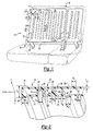
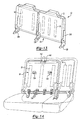
    1. A seating assembly for an automotive vehicle, comprising a seat back (12) formed from a molded plastic having a forward wall portion (16) and a rearward wall portion (14), and a plurality of individual integrated reinforcement structures (42,46,48,50) for defining an integrated reinforcement structure pattern; and an attachment assembly for anchoring said seat back to at least one body in white portion of said automotive vehicle;
      wherein the attachment assembly includes a channel-shaped member, affixed to both the forward wall portion (16) and the rearward wall portion (14) of the seat back (12), such that the seating assembly is capable of
      (1) withstanding without rupture at least about 13000 Newtons in the direction in which the seat faces, in a plane parallel to the longitudinal centerline of the vehicle; and
      (2) upon rapid acceleration up to 20 to 30 times "g" (the acceleration due to gravity), exhibiting substantially no fragmentation of the seat back with at least a 36 kg mass placed behind the seat back.
    2. The seating assembly of Claim 1, wherein the seat back is a blow molded seatback.
    3. The seating assembly of Claim 1 or Claim 2, further comprising a self locking releasable retention mechanism (26) for maintaining said seat back in a generally upright position.
    4. The seating assembly of any one of Claims 1 to 3, wherein the attachment assembly comprises:
      a hinge assembly having a bracket portion including a first side wall portion, an opposing second side wall portion and an intermediate wall, said walls adjoined to one another defining a channel for receiving said seat back and a pivot member (76) for hingedly anchoring said seat back directly to a first body in white portion of said automotive vehicle;
      a latch (112) secured to a second body in white portion of an automotive vehicle; and
      a striker having a projecting striker bar (118) attached to a mounting portion (116) in overlapping engagement with said rearward wall portion of said seat back (12) for interferingly engaging said latch to maintain said seat back in a generally upright position.
    5. The seating assembly of any one of Claims 1 to 4, wherein said seat back is formed from a plastic selected from polystyrenics, polyamides, polyolefins, polycarbonates or mixtures thereof.
    6. The seating assembly of any of any one of Claims 1 to 4, wherein said molded plastic includes a polyesterpolycarbonate.
    7. The seating assembly of any one of Claims 1 to 6, wherein said seating assembly is adapted for a vehicle free standing seat.
    8. The seating assembly of any one of Claims 1 to 7, wherein a plurality of said individual integrated reinforcement structures includes a tack-off having a plurality of walls.
    9. The seating assembly of any one of Claims 1 to 8, wherein a plurality of said individual integrated reinforcement structures includes at least one wall rib.
    10. The seating assembly of any one of Claims 1 to 9, further comprising a supplemental reinforcing insert configured for placement between said forward wall portion and said rearward wall portion of said seat back.
    EP01935710A 2000-06-01 2001-05-18 Improved seating system and method for making the same Expired - Lifetime EP1286852B1 (en)

    Applications Claiming Priority (7)

    Application Number Priority Date Filing Date Title
    US20869400P 2000-06-01 2000-06-01
    US208694P 2000-06-01
    US24301200P 2000-10-24 2000-10-24
    US243012P 2000-10-24
    US766792 2001-01-22
    US09/766,792 US6491346B1 (en) 2000-06-01 2001-01-22 Seating system and method for making the same
    PCT/US2001/016266 WO2001092051A1 (en) 2000-06-01 2001-05-18 Improved seating system and method for making the same

    Publications (2)

    Publication Number Publication Date
    EP1286852A1 EP1286852A1 (en) 2003-03-05
    EP1286852B1 true EP1286852B1 (en) 2005-08-31

    Family

    ID=27395241

    Family Applications (1)

    Application Number Title Priority Date Filing Date
    EP01935710A Expired - Lifetime EP1286852B1 (en) 2000-06-01 2001-05-18 Improved seating system and method for making the same

    Country Status (8)

    Country Link
    US (4) US6491346B1 (en)
    EP (1) EP1286852B1 (en)
    AU (1) AU2001261779A1 (en)
    CA (1) CA2410261C (en)
    DE (1) DE60113102T2 (en)
    ES (1) ES2244620T3 (en)
    MX (1) MXPA02011856A (en)
    WO (1) WO2001092051A1 (en)

    Cited By (3)

    * Cited by examiner, † Cited by third party
    Publication number Priority date Publication date Assignee Title
    US8511748B2 (en) 2008-05-28 2013-08-20 Styron Europe Gmbh Vehicular seat back assembly
    US8998316B2 (en) 2010-06-07 2015-04-07 Styron Europe Gmbh Seating assembly with a blow molded seat back
    EP2663445B1 (en) 2011-01-12 2016-08-10 Salflex Polymers Limited Blow-molded hollow article with pillar structural members and blow molding process

    Families Citing this family (111)

    * Cited by examiner, † Cited by third party
    Publication number Priority date Publication date Assignee Title
    US7040696B2 (en) 1998-10-30 2006-05-09 Indiana Mills & Manufacturing, Inc. System of seats for a vehicle
    US6886889B2 (en) * 1998-10-30 2005-05-03 Indiana Mills & Manufacturing, Inc. Restraint system for a vehicle
    US6491346B1 (en) * 2000-06-01 2002-12-10 Dow Global Technologies, Inc. Seating system and method for making the same
    DE10126014C1 (en) * 2001-05-28 2003-01-09 Porsche Ag Folding backrest for a rear seat of a motor vehicle
    DE60205492T2 (en) 2001-08-15 2006-06-08 Dow Global Technologies, Inc., Midland IMPROVED SEATING SYSTEM
    DE10142981B4 (en) * 2001-09-01 2005-04-21 Keiper Gmbh & Co. Kg Backrest cushion support for a vehicle seat
    US6786551B2 (en) * 2001-10-08 2004-09-07 Lear Corporation Seat latching assembly
    US6669259B2 (en) * 2001-11-09 2003-12-30 Pro-Gard Industries, L.P. Vehicle partition
    US6783184B2 (en) * 2002-01-17 2004-08-31 Bayer Polymers Llc Molded article having a rigid support and a flexible hollow member
    US7144085B2 (en) * 2002-03-05 2006-12-05 Indiana Mills & Manufacturing, Inc. Passenger restraint system
    US6896324B1 (en) * 2002-04-19 2005-05-24 Adam Aircraft Industries Hybrid composite-metal energy absorbing seat
    US7128373B2 (en) * 2002-09-27 2006-10-31 Dow Global Technologies, Inc. Seating system and method of forming same
    DE10250218A1 (en) * 2002-10-23 2004-05-06 Volkswagen Ag Weight-optimized backrest for a motor vehicle seat
    US7250091B2 (en) * 2003-02-13 2007-07-31 Dow Global Technologies Inc Method of forming a seating system
    FR2856351B1 (en) * 2003-06-20 2005-10-28 Faurecia Sieges Automobile SEAT BACK FOLDING OF A MOTOR VEHICLE, AND METHOD OF MAKING SUCH A REINFORCEMENT
    US7383911B2 (en) * 2003-09-19 2008-06-10 Ford Global Technologies Llc Wireless seatbelt buckle switch harvesting energy and method therefor
    US7536973B2 (en) * 2005-01-07 2009-05-26 Plastic Safety Systems, Inc. Plastic blow molded board-like members
    FR2868023B1 (en) * 2004-03-26 2006-06-02 Faurecia Sieges Automobile VEHICLE SEAT BACKREST SUITABLE FOR PERMITTING THE FIXING OF A CHILD SEAT AND VEHICLE SEAT COMPRISING SUCH A DOSSIER
    KR100733134B1 (en) * 2005-04-29 2007-06-28 주식회사 엘지화학 Frame panel
    DE102005028929B4 (en) * 2005-06-22 2009-04-09 Wilhelm Karmann Gmbh Component group for a convertible motor vehicle
    US7980589B2 (en) * 2005-11-17 2011-07-19 Salflex Polymers Ltd. Inflatable bolster
    US8128174B2 (en) * 2006-01-31 2012-03-06 Lear Corporation Pocketed molded vehicle backrest
    US7585027B2 (en) 2006-04-07 2009-09-08 Schukra Of North America Overmolded thin-profile lumbar support
    EP1857321A2 (en) * 2006-05-18 2007-11-21 Nissan Motor Co., Ltd. Seat structure
    US7775603B2 (en) * 2006-06-29 2010-08-17 L & P Property Management Company Seat suspension system and seat cushion module holder
    WO2008009690A2 (en) * 2006-07-21 2008-01-24 Basf Se Modular seat back assembly
    DE102006038785A1 (en) * 2006-08-18 2008-02-21 Johnson Controls Gmbh Metal structure for interior furnishing decoration of motor vehicle, has base plate, reinforcing plate and reinforcement profiles, where base plate or reinforcing plate has multiple small-area stampings
    US7887668B2 (en) * 2006-08-30 2011-02-15 Dow Global Technologies Inc. Amine organoborane polymerizable compostion and uses therefor
    US7497521B2 (en) * 2006-08-30 2009-03-03 Honda Motor Co., Ltd Seat belt retractor mounting system
    DE102006046877B4 (en) * 2006-10-04 2021-08-05 Volkswagen Ag Mountable bulkhead between the passenger compartment and trunk
    JP4682963B2 (en) * 2006-10-26 2011-05-11 日産自動車株式会社 Frame structure for vehicle seat back
    US20080145635A1 (en) * 2006-12-15 2008-06-19 General Electric Company Automotive interior structural components with integral close-out panel
    US7842146B2 (en) 2007-01-26 2010-11-30 Dow Global Technologies Inc. Ultrasonic energy for adhesive bonding
    US20080211275A1 (en) * 2007-03-02 2008-09-04 M2K, Llc. Seat assembly for a vehicle and a method of manufacturing the same
    WO2008121754A1 (en) * 2007-03-30 2008-10-09 Dow Global Technologies, Inc. Foam reinforced vehicular seating system
    US7854479B2 (en) * 2007-04-30 2010-12-21 L&P Property Management Company Overmolded lumbar support apparatus and method
    US20080277976A1 (en) * 2007-05-10 2008-11-13 M&C Corporation Seat back assist
    DE102007053962A1 (en) * 2007-07-18 2009-01-22 Johnson Controls Gmbh Structure for vehicle seat
    DE102007053964A1 (en) * 2007-07-18 2009-01-22 Johnson Controls Gmbh Structure for a vehicle seat
    DE102007041222A1 (en) * 2007-08-31 2009-03-05 Lear Corp., Southfield Vehicle seat composite frame
    DE102008036646A1 (en) * 2007-10-26 2009-04-30 C. Rob. Hammerstein Gmbh & Co. Kg Frame side part of a vehicle seat
    US7753435B2 (en) * 2007-11-26 2010-07-13 Chrysler Group Llc Water shield for vehicle door
    US20090184562A1 (en) * 2008-01-18 2009-07-23 International Truck Intellectual Property Company, Llc School bus seat frame back attachment
    US20090189321A1 (en) * 2008-01-29 2009-07-30 Dow Global Technologies Inc. Thermoplastic composition and use for large parison blow molding applications
    DE102008020290B4 (en) * 2008-04-22 2015-02-19 Johnson Controls Gmbh Structural part and vehicle seat with a backrest
    FR2930476B1 (en) * 2008-04-25 2013-08-30 Rehau Sa PLASTIC PLASTIC PIECE, BLOWN OR INJECTED, WITH IMPROVED RIGIDITY
    FR2931113B1 (en) 2008-05-16 2010-08-13 Rehau Sa FOLDING SEAT BACKBACK FOR VEHICLE
    WO2009142649A1 (en) * 2008-05-23 2009-11-26 Dow Global Technologies Inc. Improved vehicular seating system
    JP5408688B2 (en) * 2008-05-28 2014-02-05 株式会社デルタツーリング Sheet
    US8845019B2 (en) * 2008-06-06 2014-09-30 Nissan Motor Co., Ltd. Folding type seat
    US7959233B2 (en) * 2008-12-19 2011-06-14 Toyota Motor Engineering & Manufacturing North America, Inc. Seat back assembly with integral reinforcement structure
    US8414053B2 (en) 2008-12-19 2013-04-09 Toyota Motor Engineering & Manufacturing North America, Inc. Seat back assembly with integral reinforcement structure
    US8157322B2 (en) * 2008-12-22 2012-04-17 Toyota Motor Engineering & Manufacturing North America, Inc. Seat back assembly with low density frame
    US7954899B2 (en) * 2008-12-22 2011-06-07 Toyota Motor Engineering & Manufacturing North America, Inc. Seat back assembly with an adjustable headrest
    NL2002430C2 (en) * 2009-01-19 2010-07-20 Bonne Mechanisatie B V D Improved car seat.
    DE102009012772A1 (en) * 2009-03-13 2010-09-16 Koki Technik Seating Systems Gmbh Motor vehicle seat, has seat depth adjustment mechanism for adjustment of seat depth, where backrest and seat are connected by mechanism and base body of backrest and/or seat is made of plastic
    DE102009012782B4 (en) * 2009-03-13 2014-02-27 Kokinetics Gmbh vehicle seat
    US8864239B2 (en) * 2009-07-10 2014-10-21 Johnson Controls Technology Company Vehicle seat back rest structure
    US9254770B2 (en) 2009-09-22 2016-02-09 Johnson Controls Gmbh Method for producing a rear wall of a seat backrest
    DE102009050840A1 (en) * 2009-10-20 2011-06-09 Keiper Gmbh & Co. Kg Backrest locking connection for backrest of rear seat system of motor vehicle, has retainer provided for backrest lock, where retainer is formed with backrest part and formed with reinforcement in strengthened manner
    DE102009050839B4 (en) * 2009-10-20 2022-03-03 Adient Luxembourg Holding S.À R.L. Backrest, in particular for a rear seat system of a motor vehicle
    JP5511310B2 (en) * 2009-10-27 2014-06-04 日本発條株式会社 Vehicle seat
    FR2952593B1 (en) * 2009-11-13 2011-10-28 Rehau Sa METHOD FOR RIGIDIFYING A SEAT BACK BODY OF BLOWN PLASTIC MATERIAL
    US8042855B2 (en) * 2009-11-24 2011-10-25 Honda Motor Co., Ltd. Lateral slide vehicle seat
    IT1399531B1 (en) * 2010-04-09 2013-04-19 Arper Spa SEAT ELEMENT
    DE102010016775B3 (en) * 2010-05-04 2011-11-17 MöllerTech GmbH Method for manufacturing seat component with head support receiver, particularly motor vehicle seat component, involves providing receiving structure for mounting head support unit
    FR2959702B1 (en) * 2010-05-07 2012-05-18 Rehau Sa FLAT PLASTIC SEAT BACK BODY HAVING AN ANCHORING DEVICE FOR SECURELY ATTACHING A CHILD SEAT.
    DE102010024715A1 (en) * 2010-06-23 2011-12-29 Volkswagen Ag Backrest of a motor vehicle seat
    EP2412571B1 (en) * 2010-07-28 2020-04-15 Adient Luxembourg Holding S.à r.l. Seat backrest for a vehicle seat and method for producing a seat backrest for a vehicle seat
    DE102010036798B4 (en) * 2010-08-02 2022-09-29 Kokinetics Gmbh seat part
    DE102010039361A1 (en) * 2010-08-16 2012-02-16 Brose Fahrzeugteile Gmbh & Co. Kommanditgesellschaft, Coburg Vehicle seat with several fittings
    JP5189146B2 (en) * 2010-08-26 2013-04-24 トヨタ紡織株式会社 Vehicle seat
    US9180791B2 (en) * 2010-12-01 2015-11-10 Salflex Polymers Limited Seat-back with anchorage bar
    DE202011000563U1 (en) 2011-03-11 2011-05-12 MöllerTech GmbH Seatback component and seatback system
    JP2012254686A (en) 2011-06-08 2012-12-27 Toyota Boshoku Corp Vehicle seat
    JP5799097B2 (en) * 2011-07-05 2015-10-21 日本発條株式会社 Fastening structure for vehicle seat
    EP2546098B1 (en) * 2011-07-13 2015-07-08 C.R.F. Società Consortile per Azioni Method for manufacturing different backrests of motor vehicle rear seats and a set backrests produced according to this method
    US8851569B2 (en) * 2011-09-23 2014-10-07 Chang-Hsien Ho Full-cover and light-weight safety seat for child
    DE102011056430A1 (en) * 2011-12-14 2013-06-20 Dr. Ing. H.C. F. Porsche Ag Automotive seat
    US8746772B2 (en) * 2011-12-20 2014-06-10 Honda Motor Co., Ltd. Seating assembly for a vehicle
    DE102012207118A1 (en) * 2012-04-27 2013-10-31 Bayerische Motoren Werke Aktiengesellschaft Plastic component
    DE102012009505A1 (en) * 2012-05-14 2013-11-14 Johnson Controls Gmbh COMPONENT ASSEMBLY, VEHICLE SEAT AND MANUFACTURING PROCESS
    DE102012214039A1 (en) * 2012-05-29 2013-12-05 Keiper Gmbh & Co. Kg Backrest part for a seat, in particular a vehicle seat
    JP5961453B2 (en) * 2012-06-11 2016-08-02 日本発條株式会社 Vehicle seat
    DE102012018261A1 (en) * 2012-09-17 2014-03-20 GM Global Technology Operations, LLC (n.d. Ges. d. Staates Delaware) Pivot joint assembly for e.g. rear seat arranged in e.g. passenger car, has power and/or signal transmission device that is formed between vehicle onboard network and electrical load, for wirelessly transmitting power and/or signal
    US11304528B2 (en) 2012-09-20 2022-04-19 Steelcase Inc. Chair assembly with upholstery covering
    USD697726S1 (en) 2012-09-20 2014-01-21 Steelcase Inc. Chair
    DE102013003787B4 (en) * 2012-11-30 2022-09-08 Adient Us Llc vehicle seat
    US9004606B2 (en) 2013-04-17 2015-04-14 H.O. Bostrom Company, Inc. Emergency vehicle seat with integrated seat belt and height adjustable webbing guide
    DE102013012291A1 (en) * 2013-07-24 2015-01-29 Man Truck & Bus Ag Vehicle seat, in particular passenger seat for a bus
    JP5915603B2 (en) * 2013-08-29 2016-05-11 トヨタ自動車株式会社 Seat back frame structure
    DE102013021692A1 (en) * 2013-12-19 2015-06-25 GM Global Technology Operations LLC (n. d. Ges. d. Staates Delaware) Automotive seat element
    DE102013021864A1 (en) 2013-12-20 2015-06-25 GM Global Technology Operations LLC (n. d. Ges. d. Staates Delaware) Vehicle seat for a motor vehicle
    JP6181563B2 (en) * 2014-01-22 2017-08-16 テイ・エス テック株式会社 Vehicle seat
    JP6256121B2 (en) * 2014-03-12 2018-01-10 スズキ株式会社 Vehicle seat structure
    CN104494472A (en) * 2014-05-28 2015-04-08 苏州雷姆斯汽车工程有限公司 Carbon fiber reinforced safety seat base
    JP6387258B2 (en) * 2014-07-10 2018-09-05 日本発條株式会社 Seat back frame and vehicle seat
    US9616779B2 (en) * 2014-10-20 2017-04-11 Lear Corporation Seat assembly having a latch mechanism
    WO2017058760A1 (en) * 2015-10-02 2017-04-06 Johnson Controls Technology Company Blow molded plastic automobile seat structure
    US10576857B2 (en) 2016-02-12 2020-03-03 Adient Luxembourg Holding S.Á R.L. Seat back frame
    JP6680089B2 (en) * 2016-06-07 2020-04-15 スズキ株式会社 Vehicle seat back assembly
    JP6828338B2 (en) * 2016-09-21 2021-02-10 トヨタ紡織株式会社 Vehicle seat
    JP6780404B2 (en) * 2016-09-21 2020-11-04 トヨタ紡織株式会社 Vehicle seat
    US10308203B2 (en) * 2017-06-20 2019-06-04 Ford Global Technologies, Llc Stab proof back panel for law enforcement vehicle
    US11685303B2 (en) 2018-08-31 2023-06-27 Daniel R. Brettschneider Berth apparatus and methods using physiological parameters for controlling berth motion to promote relaxation and to induce sleep
    EP3847053B1 (en) 2018-09-04 2023-10-25 Safran Seats USA LLC Light weight metal back with extra living space
    EP3643563A1 (en) * 2018-10-24 2020-04-29 Volvo Car Corporation A frame structure for a vehicle seat backrest
    US10681983B2 (en) * 2018-11-15 2020-06-16 Series International, Llc Beam seating system
    US11026515B2 (en) 2018-11-15 2021-06-08 Series International, Llc Beam seating system
    DE102019214933B4 (en) * 2019-09-27 2023-07-06 Lear Corporation seating arrangement
    US11820275B2 (en) 2020-10-30 2023-11-21 Daniel R. Brettschneider Carrier platform with suspension mechanism for supporting a vibration-sensitive load on a vehicle

    Family Cites Families (80)

    * Cited by examiner, † Cited by third party
    Publication number Priority date Publication date Assignee Title
    US2572482A (en) * 1948-05-01 1951-10-23 American Seating Co Vehicle chair
    US2838100A (en) * 1955-12-12 1958-06-10 John W Follows Chair, sofa, or similar article
    US3054643A (en) * 1960-07-18 1962-09-18 Finkel Outdoor Prod Chairs with snap-on slats and such slats
    US3171691A (en) * 1963-07-17 1965-03-02 Ford Motor Co Seat construction
    US3245715A (en) * 1964-09-08 1966-04-12 Jules C Gits Molded articles and methods of making same
    US3638997A (en) 1970-03-04 1972-02-01 Scott N Shapiro Temporary seat supported by spaced-apart chairs
    US3712614A (en) 1970-07-17 1973-01-23 Cambridge Res & Dev Group Swing seat
    US3669496A (en) 1970-12-03 1972-06-13 American Desk Mfg Co Chair and seat and back unit therefor
    US3797887A (en) * 1971-06-28 1974-03-19 American Seating Co Seat for urban mass transit vehicles
    FR2240424A1 (en) 1973-08-08 1975-03-07 Bally Georges Hot water or steam boiler - cylindrical extension above combustion chamber is joined to annular gas chamber
    US3947068A (en) * 1974-04-22 1976-03-30 Steelcase Inc. Chair
    US4065182A (en) 1976-08-30 1977-12-27 General Motors Corporation Cushion retention for a vehicle seat
    US4088367A (en) 1977-06-20 1978-05-09 Rohr Industries, Inc. Vehicle seat assembly
    US4118061A (en) * 1977-07-25 1978-10-03 Rohr Industries, Inc. Vehicle seat assembly
    US4133579A (en) 1977-08-29 1979-01-09 American Desk Manufacturing Co. Stadium, gymnasium or like chair
    US4142757A (en) 1977-10-27 1979-03-06 K & M Plastics, Inc. Fold down multi-purpose vehicle seat back core or the like automotive structural member
    US4246734A (en) 1978-10-18 1981-01-27 K & M Plastics Inc. Fold down multi-purpose vehicle seat back core with inmolded metal reenforcing member
    FR2420424A1 (en) 1978-03-21 1979-10-19 Permali Sa Timber-reinforced moulded fibreboard panels for vehicle bench seats - minimise wt. and acoustic drumming c.f. use of pressed steel panels
    US4186966A (en) * 1978-05-05 1980-02-05 Coach & Car Equipment Corporation Metal seat frame with adhesively secured exterior plastic parts
    DE2902386A1 (en) * 1979-01-23 1980-07-24 Vogel Ignaz Fahrzeugsitze SEAT
    JPS55150348A (en) 1979-05-11 1980-11-22 Mitsui Petrochemical Ind Seat
    US4275925A (en) * 1979-07-10 1981-06-30 Coach And Car Equipment Corporation Back shroud for seat
    JPS56120319A (en) 1980-02-27 1981-09-21 Showa Denko Kk Core material of synthetic resin for sheet of vehicle and its manufacture
    US4556254A (en) * 1981-12-15 1985-12-03 Bio-Support Industries Limited Backrest
    JPS6024918A (en) 1983-07-20 1985-02-07 Tokyo Seat Kk Manufacture of head rest cover
    JPS6024917A (en) 1983-07-20 1985-02-07 Tokyo Seat Kk Manufacture of head rest cover
    JPS61114835A (en) 1984-11-09 1986-06-02 Nissan Shatai Co Ltd Blow molding apparatus
    DE3513807A1 (en) 1985-04-17 1986-10-23 Adam Opel AG, 6090 Rüsselsheim STORAGE OR LOCKING DEVICE, IN PARTICULAR FOR PIVOTING MOTOR VEHICLE SEATS
    DE3609591A1 (en) * 1986-03-21 1988-01-21 Grammer Sitzsysteme Gmbh SEAT
    US4776633A (en) * 1986-04-10 1988-10-11 Steelcase Inc. Integrated chair and control
    FR2602654B1 (en) * 1986-08-14 1988-11-25 Peugeot Cycles SEAT STRUCTURE, PARTICULARLY FOR SEAT WITH ADJUSTABLE BACK
    CA1243930A (en) * 1987-08-07 1988-11-01 Roland Leblanc Collapsible infant seat
    DE3841532A1 (en) 1988-12-09 1990-06-13 Bayer Ag BACKREST SUPPORT STRUCTURE FOR A VEHICLE SEAT AND VEHICLE SEAT BACKREST WITH THIS BACKREST SUPPORT STRUCTURE
    JPH0347728A (en) 1989-07-14 1991-02-28 Mazda Motor Corp Blow molding method of resin molded item
    JP2526693Y2 (en) 1989-11-15 1997-02-19 株式会社東洋シート Seat frame structure of vehicle seat
    US5240310A (en) * 1989-11-30 1993-08-31 Bayer Aktiengesellschaft Seat base for vehicle seats
    US5224756A (en) * 1991-05-14 1993-07-06 The United States Of America As Represented By The Director Of The National Security Agency Integrated child seat for vehicle
    JPH0817730B2 (en) * 1991-05-21 1996-02-28 株式会社イトーキ Shell structure in chair with back and seat synchronized movement
    US5253924A (en) 1991-06-11 1993-10-19 Concept Analysis Corporation Blow molded seat back with integral reinforcing member
    US5133588A (en) 1991-06-14 1992-07-28 Deere & Company Seat assembly with integral fuel tank
    US5282667A (en) * 1991-12-20 1994-02-01 Hoover Universal, Inc. Vehicle seat assembly with integral child seat
    DE4208150A1 (en) 1992-03-13 1993-09-16 Bayerische Motoren Werke Ag Backrest frame for vehicle seat - uses crosspiece and diagonal strut to distribute effects of side loads.
    US5375914A (en) * 1992-05-12 1994-12-27 J. G. Furniture Systems, Inc. Public seating chair
    US5540479A (en) * 1992-05-22 1996-07-30 Thomas; Alan V. Vehicle seats
    GB2267223B (en) * 1992-05-29 1995-04-26 Sutcliffe Leisure Ltd Seats for swings
    US5280995A (en) * 1992-11-13 1994-01-25 Hoover Universal, Inc. Vehicle seat assembly with rotating seat pack panel and integral child seat
    FR2698832B1 (en) 1992-12-08 1995-02-24 Peugeot Modular seat structure for a motor vehicle.
    US5437498A (en) * 1994-02-22 1995-08-01 Hoover Universal, Inc. Vehicle seat with side bolster reinforcement
    US5575533A (en) 1994-02-25 1996-11-19 Concept Analysis Corp. Blow molded seat frame with integral reinforcement
    US5597205A (en) 1994-02-25 1997-01-28 Concept Analysis Corporation Energy absorbing restraint seat back recliner for application on a restraint safety seat
    US5499859A (en) * 1994-05-04 1996-03-19 Steelcase, Inc. Upholstery attachment device and upholstered article using same
    US5505520A (en) * 1994-11-03 1996-04-09 Ford Motor Company Passenger seat with adjustable lumbar support
    US5704685A (en) * 1994-12-27 1998-01-06 Nhk Spring Co., Ltd. Vehicle rear seat provided with child seat
    US5601334A (en) * 1995-07-14 1997-02-11 Hoover Universal, Inc. Integrated child seat with detachable booster seat
    US5603550A (en) * 1995-10-18 1997-02-18 Douglas & Lomason Company Vehicle seat interlock system
    US5700054A (en) * 1996-04-23 1997-12-23 Lear Corporation Vehicle seat assembly including integral child restraint seat
    US5803543A (en) * 1996-05-17 1998-09-08 Ekkehard Grimm Child's seat for mounting on a standard seat for adults
    CA2257396A1 (en) * 1996-06-05 1997-12-11 Thomas J. Newhouse Chair construction
    US5743593A (en) * 1996-08-09 1998-04-28 Lear Corporation Vehicle seat with integral child seat
    US5722732A (en) * 1996-08-26 1998-03-03 General Motors Corporation Shoulder belt retractor with headrest support
    US5713634A (en) 1996-09-30 1998-02-03 Koike; Toshihisa Seat back structure of vehicle seat
    US6059369A (en) * 1997-05-01 2000-05-09 Lear Corporation Composite vehicle seat back frame and method of manufacturing thereof
    US5895096A (en) 1997-04-10 1999-04-20 Lear Corporation Vehicle seat back assembly and method of making a vehicle seat back assembly
    DE19728052A1 (en) 1997-07-01 1999-01-07 Basf Ag Vehicle seat
    US5951110A (en) * 1997-10-17 1999-09-14 Irwin Seating Company Contoured plastic seat back
    DE19800071A1 (en) * 1998-01-02 1999-07-08 Volkswagen Ag Restraint with a seat belt
    US6062649A (en) * 1998-03-03 2000-05-16 Steelcase Development Inc. Chair back construction
    US6079781A (en) 1998-10-13 2000-06-27 Tilley; Jay M. Ventilated child restraint seat
    US6478381B1 (en) * 1999-10-29 2002-11-12 Lear Corporation Elastomeric seat back and slide-over head rest assembly for a vehicle seat
    US6536844B2 (en) 1999-11-18 2003-03-25 Moeller Marine Products Blow-molded seat assembly and method of making same
    US6554356B1 (en) * 1999-11-30 2003-04-29 The C.E. White Co. Shock absorbing vehicle seat frame
    US6286902B1 (en) * 1999-12-10 2001-09-11 Tachi-S Co. Ltd. Seat back framework of seat
    US6328386B1 (en) * 2000-01-11 2001-12-11 Takata Seat Belts Inc. Seat belt system
    US6491346B1 (en) 2000-06-01 2002-12-10 Dow Global Technologies, Inc. Seating system and method for making the same
    FR2816262B1 (en) 2000-11-09 2003-01-31 Cera PROCESS FOR THE PRODUCTION OF A TRIM ELEMENT
    US6552929B1 (en) * 2001-02-08 2003-04-22 Advanced Micro Devices, Inc. Piggyback programming using an extended first pulse for multi-level cell flash memory designs
    US6679558B2 (en) * 2001-07-26 2004-01-20 Lear Corporation Integral blow-molded, steel reinforced automotive seating structure
    US6733064B2 (en) * 2001-08-10 2004-05-11 Lear Corporation Impact absorbing assembly for vehicle interior systems and seat backs
    DE60205492T2 (en) * 2001-08-15 2006-06-08 Dow Global Technologies, Inc., Midland IMPROVED SEATING SYSTEM
    DE10142981B4 (en) * 2001-09-01 2005-04-21 Keiper Gmbh & Co. Kg Backrest cushion support for a vehicle seat

    Cited By (4)

    * Cited by examiner, † Cited by third party
    Publication number Priority date Publication date Assignee Title
    US8511748B2 (en) 2008-05-28 2013-08-20 Styron Europe Gmbh Vehicular seat back assembly
    US8998316B2 (en) 2010-06-07 2015-04-07 Styron Europe Gmbh Seating assembly with a blow molded seat back
    EP2663445B1 (en) 2011-01-12 2016-08-10 Salflex Polymers Limited Blow-molded hollow article with pillar structural members and blow molding process
    EP2663445B2 (en) 2011-01-12 2019-05-08 ABC Group Inc. Blow-molded hollow article with pillar structural members and blow molding process

    Also Published As

    Publication number Publication date
    US6997515B2 (en) 2006-02-14
    ES2244620T3 (en) 2005-12-16
    US6688700B2 (en) 2004-02-10
    US6491346B1 (en) 2002-12-10
    CA2410261C (en) 2007-03-27
    US20060103228A1 (en) 2006-05-18
    WO2001092051A1 (en) 2001-12-06
    MXPA02011856A (en) 2004-05-17
    DE60113102D1 (en) 2005-10-06
    EP1286852A1 (en) 2003-03-05
    US20030075968A1 (en) 2003-04-24
    AU2001261779A1 (en) 2001-12-11
    DE60113102T2 (en) 2006-05-04
    US20040155513A1 (en) 2004-08-12
    US7137670B2 (en) 2006-11-21
    CA2410261A1 (en) 2001-12-06

    Similar Documents

    Publication Publication Date Title
    EP1286852B1 (en) Improved seating system and method for making the same
    US8998316B2 (en) Seating assembly with a blow molded seat back
    US7128373B2 (en) Seating system and method of forming same
    US7300102B2 (en) Instrument panel assembly
    US20110101744A1 (en) Vehicular seating system
    US20090066142A1 (en) Automobile Vehicle Passenger Seat and Process For Producing A Vehicle Passenger Seat
    EP1564067A1 (en) Improved seating system
    EP2646282B1 (en) Seat-back with anchorage bar
    WO2008121754A1 (en) Foam reinforced vehicular seating system
    US10220737B2 (en) Kinematic back panel
    Naughton et al. Eco-friendly automotive plastic seat design
    Naughton et al. Improved car seats by blow-moulded plastic seat-back design

    Legal Events

    Date Code Title Description
    PUAI Public reference made under article 153(3) epc to a published international application that has entered the european phase

    Free format text: ORIGINAL CODE: 0009012

    17P Request for examination filed

    Effective date: 20021125

    AK Designated contracting states

    Kind code of ref document: A1

    Designated state(s): AT BE CH CY DE DK ES FI FR GB GR IE IT LI LU MC NL PT SE TR

    AX Request for extension of the european patent

    Extension state: AL LT LV MK RO SI

    17Q First examination report despatched

    Effective date: 20030306

    RIN1 Information on inventor provided before grant (corrected)

    Inventor name: KURTYCZ, ERIC, R.

    Inventor name: HECKERT, MICK, F.

    Inventor name: GUPTA, VIKAS

    Inventor name: KORCHNAK, GREGORY, J.

    Inventor name: PALMIERI, JANE, M.

    Inventor name: RENY, GREGORY, P.

    RBV Designated contracting states (corrected)

    Designated state(s): DE ES FR GB IT SE

    GRAP Despatch of communication of intention to grant a patent

    Free format text: ORIGINAL CODE: EPIDOSNIGR1

    GRAS Grant fee paid

    Free format text: ORIGINAL CODE: EPIDOSNIGR3

    GRAA (expected) grant

    Free format text: ORIGINAL CODE: 0009210

    AK Designated contracting states

    Kind code of ref document: B1

    Designated state(s): DE ES FR GB IT SE

    REG Reference to a national code

    Ref country code: GB

    Ref legal event code: FG4D

    REF Corresponds to:

    Ref document number: 60113102

    Country of ref document: DE

    Date of ref document: 20051006

    Kind code of ref document: P

    REG Reference to a national code

    Ref country code: SE

    Ref legal event code: TRGR

    REG Reference to a national code

    Ref country code: ES

    Ref legal event code: FG2A

    Ref document number: 2244620

    Country of ref document: ES

    Kind code of ref document: T3

    ET Fr: translation filed
    PLBE No opposition filed within time limit

    Free format text: ORIGINAL CODE: 0009261

    STAA Information on the status of an ep patent application or granted ep patent

    Free format text: STATUS: NO OPPOSITION FILED WITHIN TIME LIMIT

    26N No opposition filed

    Effective date: 20060601

    REG Reference to a national code

    Ref country code: GB

    Ref legal event code: 732E

    Free format text: REGISTERED BETWEEN 20110728 AND 20110803

    PGFP Annual fee paid to national office [announced via postgrant information from national office to epo]

    Ref country code: IT

    Payment date: 20110528

    Year of fee payment: 11

    REG Reference to a national code

    Ref country code: FR

    Ref legal event code: CA

    Effective date: 20111010

    Ref country code: FR

    Ref legal event code: TP

    Owner name: STYRON EUROPE GMBH, CH

    Effective date: 20111010

    REG Reference to a national code

    Ref country code: ES

    Ref legal event code: PC2A

    Owner name: STYRON LLC

    Effective date: 20120412

    REG Reference to a national code

    Ref country code: FR

    Ref legal event code: GC

    Effective date: 20120423

    REG Reference to a national code

    Ref country code: ES

    Ref legal event code: PC2A

    Owner name: STYRON EUROPE GMBH

    Effective date: 20120522

    REG Reference to a national code

    Ref country code: GB

    Ref legal event code: 732E

    Free format text: REGISTERED BETWEEN 20120531 AND 20120606

    PG25 Lapsed in a contracting state [announced via postgrant information from national office to epo]

    Ref country code: IT

    Free format text: LAPSE BECAUSE OF NON-PAYMENT OF DUE FEES

    Effective date: 20120518

    PGFP Annual fee paid to national office [announced via postgrant information from national office to epo]

    Ref country code: SE

    Payment date: 20130530

    Year of fee payment: 13

    PGFP Annual fee paid to national office [announced via postgrant information from national office to epo]

    Ref country code: FR

    Payment date: 20130606

    Year of fee payment: 13

    PGFP Annual fee paid to national office [announced via postgrant information from national office to epo]

    Ref country code: GB

    Payment date: 20140527

    Year of fee payment: 14

    PGFP Annual fee paid to national office [announced via postgrant information from national office to epo]

    Ref country code: ES

    Payment date: 20140526

    Year of fee payment: 14

    PG25 Lapsed in a contracting state [announced via postgrant information from national office to epo]

    Ref country code: SE

    Free format text: LAPSE BECAUSE OF NON-PAYMENT OF DUE FEES

    Effective date: 20140519

    REG Reference to a national code

    Ref country code: SE

    Ref legal event code: EUG

    REG Reference to a national code

    Ref country code: FR

    Ref legal event code: ST

    Effective date: 20150130

    PG25 Lapsed in a contracting state [announced via postgrant information from national office to epo]

    Ref country code: FR

    Free format text: LAPSE BECAUSE OF NON-PAYMENT OF DUE FEES

    Effective date: 20140602

    REG Reference to a national code

    Ref country code: DE

    Ref legal event code: R082

    Ref document number: 60113102

    Country of ref document: DE

    Representative=s name: CASALONGA & PARTNERS, DE

    Ref country code: DE

    Ref legal event code: R081

    Ref document number: 60113102

    Country of ref document: DE

    Owner name: TRINSEO EUROPE GMBH, CH

    Free format text: FORMER OWNER: STYRON EUROPE GMBH, HORGEN, CH

    Ref country code: DE

    Ref legal event code: R081

    Ref document number: 60113102

    Country of ref document: DE

    Owner name: TRINSEO EUROPE GMBH, CH

    Free format text: FORMER OWNER: DOW GLOBAL TECHNOLOGIES INC., MIDLAND, MICH., US

    GBPC Gb: european patent ceased through non-payment of renewal fee

    Effective date: 20150518

    PG25 Lapsed in a contracting state [announced via postgrant information from national office to epo]

    Ref country code: GB

    Free format text: LAPSE BECAUSE OF NON-PAYMENT OF DUE FEES

    Effective date: 20150518

    REG Reference to a national code

    Ref country code: ES

    Ref legal event code: FD2A

    Effective date: 20160628

    PG25 Lapsed in a contracting state [announced via postgrant information from national office to epo]

    Ref country code: ES

    Free format text: LAPSE BECAUSE OF NON-PAYMENT OF DUE FEES

    Effective date: 20150519

    PGFP Annual fee paid to national office [announced via postgrant information from national office to epo]

    Ref country code: DE

    Payment date: 20180529

    Year of fee payment: 18

    REG Reference to a national code

    Ref country code: DE

    Ref legal event code: R119

    Ref document number: 60113102

    Country of ref document: DE

    PG25 Lapsed in a contracting state [announced via postgrant information from national office to epo]

    Ref country code: DE

    Free format text: LAPSE BECAUSE OF NON-PAYMENT OF DUE FEES

    Effective date: 20191203