EP1281561A2 - Abstandsbezogenes Fahrgeschwindigkeitsregelsystem - Google Patents
Abstandsbezogenes Fahrgeschwindigkeitsregelsystem Download PDFInfo
- Publication number
- EP1281561A2 EP1281561A2 EP02254709A EP02254709A EP1281561A2 EP 1281561 A2 EP1281561 A2 EP 1281561A2 EP 02254709 A EP02254709 A EP 02254709A EP 02254709 A EP02254709 A EP 02254709A EP 1281561 A2 EP1281561 A2 EP 1281561A2
- Authority
- EP
- European Patent Office
- Prior art keywords
- vehicle speed
- host
- vehicle
- control
- command
- Prior art date
- Legal status (The legal status is an assumption and is not a legal conclusion. Google has not performed a legal analysis and makes no representation as to the accuracy of the status listed.)
- Withdrawn
Links
Images


Classifications
-
- B—PERFORMING OPERATIONS; TRANSPORTING
- B60—VEHICLES IN GENERAL
- B60W—CONJOINT CONTROL OF VEHICLE SUB-UNITS OF DIFFERENT TYPE OR DIFFERENT FUNCTION; CONTROL SYSTEMS SPECIALLY ADAPTED FOR HYBRID VEHICLES; ROAD VEHICLE DRIVE CONTROL SYSTEMS FOR PURPOSES NOT RELATED TO THE CONTROL OF A PARTICULAR SUB-UNIT
- B60W30/00—Purposes of road vehicle drive control systems not related to the control of a particular sub-unit, e.g. of systems using conjoint control of vehicle sub-units
- B60W30/14—Adaptive cruise control
- B60W30/16—Control of distance between vehicles, e.g. keeping a distance to preceding vehicle
-
- B—PERFORMING OPERATIONS; TRANSPORTING
- B60—VEHICLES IN GENERAL
- B60K—ARRANGEMENT OR MOUNTING OF PROPULSION UNITS OR OF TRANSMISSIONS IN VEHICLES; ARRANGEMENT OR MOUNTING OF PLURAL DIVERSE PRIME-MOVERS IN VEHICLES; AUXILIARY DRIVES FOR VEHICLES; INSTRUMENTATION OR DASHBOARDS FOR VEHICLES; ARRANGEMENTS IN CONNECTION WITH COOLING, AIR INTAKE, GAS EXHAUST OR FUEL SUPPLY OF PROPULSION UNITS IN VEHICLES
- B60K31/00—Vehicle fittings, acting on a single sub-unit only, for automatically controlling vehicle speed, i.e. preventing speed from exceeding an arbitrarily established velocity or maintaining speed at a particular velocity, as selected by the vehicle operator
- B60K31/0008—Vehicle fittings, acting on a single sub-unit only, for automatically controlling vehicle speed, i.e. preventing speed from exceeding an arbitrarily established velocity or maintaining speed at a particular velocity, as selected by the vehicle operator including means for detecting potential obstacles in vehicle path
-
- B—PERFORMING OPERATIONS; TRANSPORTING
- B60—VEHICLES IN GENERAL
- B60K—ARRANGEMENT OR MOUNTING OF PROPULSION UNITS OR OF TRANSMISSIONS IN VEHICLES; ARRANGEMENT OR MOUNTING OF PLURAL DIVERSE PRIME-MOVERS IN VEHICLES; AUXILIARY DRIVES FOR VEHICLES; INSTRUMENTATION OR DASHBOARDS FOR VEHICLES; ARRANGEMENTS IN CONNECTION WITH COOLING, AIR INTAKE, GAS EXHAUST OR FUEL SUPPLY OF PROPULSION UNITS IN VEHICLES
- B60K6/00—Arrangement or mounting of plural diverse prime-movers for mutual or common propulsion, e.g. hybrid propulsion systems comprising electric motors and internal combustion engines
- B60K6/20—Arrangement or mounting of plural diverse prime-movers for mutual or common propulsion, e.g. hybrid propulsion systems comprising electric motors and internal combustion engines the prime-movers consisting of electric motors and internal combustion engines, e.g. HEVs
- B60K6/42—Arrangement or mounting of plural diverse prime-movers for mutual or common propulsion, e.g. hybrid propulsion systems comprising electric motors and internal combustion engines the prime-movers consisting of electric motors and internal combustion engines, e.g. HEVs characterised by the architecture of the hybrid electric vehicle
- B60K6/48—Parallel type
-
- B—PERFORMING OPERATIONS; TRANSPORTING
- B60—VEHICLES IN GENERAL
- B60W—CONJOINT CONTROL OF VEHICLE SUB-UNITS OF DIFFERENT TYPE OR DIFFERENT FUNCTION; CONTROL SYSTEMS SPECIALLY ADAPTED FOR HYBRID VEHICLES; ROAD VEHICLE DRIVE CONTROL SYSTEMS FOR PURPOSES NOT RELATED TO THE CONTROL OF A PARTICULAR SUB-UNIT
- B60W2520/00—Input parameters relating to overall vehicle dynamics
- B60W2520/10—Longitudinal speed
- B60W2520/105—Longitudinal acceleration
-
- B—PERFORMING OPERATIONS; TRANSPORTING
- B60—VEHICLES IN GENERAL
- B60W—CONJOINT CONTROL OF VEHICLE SUB-UNITS OF DIFFERENT TYPE OR DIFFERENT FUNCTION; CONTROL SYSTEMS SPECIALLY ADAPTED FOR HYBRID VEHICLES; ROAD VEHICLE DRIVE CONTROL SYSTEMS FOR PURPOSES NOT RELATED TO THE CONTROL OF A PARTICULAR SUB-UNIT
- B60W2710/00—Output or target parameters relating to a particular sub-units
- B60W2710/06—Combustion engines, Gas turbines
- B60W2710/0666—Engine torque
-
- B—PERFORMING OPERATIONS; TRANSPORTING
- B60—VEHICLES IN GENERAL
- B60W—CONJOINT CONTROL OF VEHICLE SUB-UNITS OF DIFFERENT TYPE OR DIFFERENT FUNCTION; CONTROL SYSTEMS SPECIALLY ADAPTED FOR HYBRID VEHICLES; ROAD VEHICLE DRIVE CONTROL SYSTEMS FOR PURPOSES NOT RELATED TO THE CONTROL OF A PARTICULAR SUB-UNIT
- B60W2720/00—Output or target parameters relating to overall vehicle dynamics
- B60W2720/10—Longitudinal speed
- B60W2720/106—Longitudinal acceleration
-
- Y—GENERAL TAGGING OF NEW TECHNOLOGICAL DEVELOPMENTS; GENERAL TAGGING OF CROSS-SECTIONAL TECHNOLOGIES SPANNING OVER SEVERAL SECTIONS OF THE IPC; TECHNICAL SUBJECTS COVERED BY FORMER USPC CROSS-REFERENCE ART COLLECTIONS [XRACs] AND DIGESTS
- Y02—TECHNOLOGIES OR APPLICATIONS FOR MITIGATION OR ADAPTATION AGAINST CLIMATE CHANGE
- Y02T—CLIMATE CHANGE MITIGATION TECHNOLOGIES RELATED TO TRANSPORTATION
- Y02T10/00—Road transport of goods or passengers
- Y02T10/60—Other road transportation technologies with climate change mitigation effect
- Y02T10/62—Hybrid vehicles
Definitions
- the present invention relates to an adaptive cruise control (ACC) system which executes a following control for following a preceding vehicle ahead of a host-vehicle while keeping a predetermined inter-vehicle distance, and more particularly to an ACC system which cancels the following control for keeping the inter-vehicle distance when a host-vehicle speed becomes smaller than a control-cancel,vehicle speed.
- ACC adaptive cruise control
- Japanese Patent Provisional Publication No. 2000-313245 discloses a following control system which cancels a following control by decreasing a deceleration of a host-vehicle according to elapsed time.
- this control system is arranged to decrease a deceleration according to the elapse of time with a predetermined constant gradient when the host-vehicle speed becomes lower than a preset vehicle speed.
- This arrangement varies a control-cancel vehicle speed according to the magnitude of the deceleration, and therefore a driver of the host-vehicle may receive a strange feeling therefrom.
- ACC adaptive cruise control
- An aspect of the present invention resides an adaptive cruise control (ACC) system for a host-vehicle which system comprises a controller.
- the controller is programmed to detect an inter-vehicle distance between the host-vehicle and a preceding vehicle ahead of the host-vehicle, to detect a host-vehicle speed of the host-vehicle, to calculate a command vehicle speed on the basis of the inter-vehicle distance and the host-vehicle speed to bring the inter-vehicle distance closer to a target inter-vehicle distance, to control one of a driving force and a braking force according to the command vehicle speed, to cancel controlling one of the driving force and the braking force according to the command vehicle speed when the host-vehicle speed is lower than or equal to a control-cancel vehicle speed, and to gradually decrease a deceleration of the host-vehicle according to an approach of the host-vehicle speed toward the control-cancel vehicle speed when the host-vehi
- an adaptive cruise control (ACC) system for a host-vehicle which system comprises a controller.
- the controller is programmed to detect an inter-vehicle distance between the host-vehicle and a preceding vehicle ahead of the host-vehicle, to detect a host-vehicle speed of the host-vehicle, to calculate a command vehicle speed on the basis of the inter-vehicle distance and the host-vehicle speed to bring the inter-vehicle distance closer to a target inter-vehicle distance, to control one of a driving force and a brake hydraulic pressure according to the command vehicle speed, to cancel controlling one of the driving force and the brake hydraulic pressure according to the command vehicle speed when the host-vehicle speed is lower than or equal to a control-cancel vehicle speed, and to gradually decrease the brake hydraulic pressure according to an approach of the host-vehicle speed toward the control-cancel vehicle speed when the host-vehicle speed becomes lower than or equal to a gradual-
- ACC adaptive cruise
- a further other aspect of the present invention resides in a method of executing an adaptive cruise control of a host-vehicle.
- the method comprises a step of detecting an inter-vehicle distance between the host-vehicle and a preceding vehicle ahead of the host-vehicle; a step of detecting a vehicle speed of the host-vehicle; a step of calculating a command vehicle speed on the basis of the inter-vehicle distance and the host-vehicle speed to bring the inter-vehicle distance closer to a target inter-vehicle distance; a step of controlling one of a driving force and a braking force according to the command vehicle speed; a step of canceling to control one of a driving force and a braking force according to the command vehicle speed when the host-vehicle speed is smaller than or equal to a control-cancel vehicle speed; and a step of gradually decreasing a deceleration of the host-vehicle according to an approach of the host-vehi
- FIGs 1 to 11 there is shown a first embodiment of an adaptive cruise control (ACC) system for a host-vehicle 1 in accordance with the present invention.
- This ACC control system mainly executes a preceding-vehicle following control for following a preceding vehicle ahead of host-vehicle 1.
- Inter-vehicle distance sensor 2 is attached at a front end portion of host-vehicle 1.
- Inter-vehicle distance sensor 2 employed in this first embodiment is of a radar type which sweepingly emits laser beam in the forward direction and receives the reflection beam thereof to detect a distance to an obstacle reflecting the laser beam.
- Other type such as a radio-wave type or an ultrasonic type may be employed as inter-vehicle distance sensor 2.
- Host vehicle 1 comprises an internal combustion engine 3 which generates rotational driving force.
- the rotational driving force generated by internal combustion engine 3 is transmitted to an automatic transmission 4 in which a gear ratio is automatically selected according to a desired vehicle speed and/or an engine torque.
- the power outputted from automatic transmission 4 is transmitted to driven wheels (front wheels and/or rear wheels) of host-vehicle 1.
- a brake actuator 5 such as a disc brake is attached to each wheel.
- a vehicle speed sensor 6 is attached to an output shaft of automatic transmission 4 and outputs a periodical pulse train responsive to a rotation speed of the output shaft of automatic transmission 4.
- Engine 3 is equipped with a throttle actuator 7 which is capable of opening and closing a throttle valve of engine 3 according to a throttle opening signal. That is, by properly controlling the opening of the throttle valve, throttle actuator 7 controls an intake air quantity of engine 3 and thereby controlling an engine output.
- Brake actuator 5 and throttle actuator 7 are controlled by a following controller 8.
- control 8 receives signals from inter-vehicle distance sensor 2 and vehicle speed sensor 6.
- controller 8 executes an adaptive cruise control (ACC) control for following a preceding-vehicle ahead of host-vehicle 1 while keeping a proper inter-vehicle distance therebetween, by controlling brake actuators 5 and throttle actuator 7 on the basis of an inter-vehicle distance L detected by inter-vehicle distance sensor 2 and a host-vehicle speed V S detected by vehicle speed sensor 6.
- ACC adaptive cruise control
- controller 8 comprises a microcomputer and peripheral devices of the microcomputer and further comprises a control block in the form of software previously stored therein as shown in Fig. 2.
- This control block shown in Fig. 2 comprises a distance signal processing section 21, a vehicle speed signal processing section 30, an inter-vehicle distance control section 40, a vehicle speed control section 50, a drive shaft torque control section 60, a brake hydraulic pressure servo system 100 and a throttle opening servo system 110.
- Distance signal processing section 21 measures a time period from a moment of sweepingly emitting laser beam from inter-vehicle distance sensor 2 to a moment of receiving reflected beam of a preceding vehicle and calculates inter-vehicle distance L between the preceding-vehicle and the host-vehicle 1 on the basis of the measured time period.
- Vehicle speed signal processing section 30 measures a cycle period of vehicle speed indicative pulses outputted from vehicle speed sensor 6 and calculates host vehicle speed V S on the basis of the measured cycle period.
- Inter-vehicle distance control section 40 calculates a command vehicle speed (target vehicle speed) V* needed for maintaining inter-vehicle distance L at target inter-vehicle distance L* on the basis of inter-vehicle distance L calculated at distance signal processing section 21 and host-vehicle speed V S calculated at vehicle speed signal processing section 30.
- Vehicle speed control section 50 calculates a command drive-shaft torque (target drive-shaft torque) T W * on the basis of command vehicle speed V* calculated at inter-vehicle distance control section 40.
- Drive shaft torque control section 60 calculates a command throttle opening ⁇ * to be supplied to throttle actuator 7 and a command brake hydraulic pressure P B * to be supplied to brake actuators 5 on the basis of target drive-shaft torque T W *.
- Drive shaft torque control section 60 outputs command throttle opening ⁇ * to throttle opening servo system 110 and outputs command brake hydraulic pressure P B * to brake hydraulic pressure servo system 100.
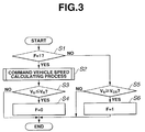
- Inter-vehicle distance control section 40 executes an inter-vehicle distance control process shown in Fig. 3.
- the inter-vehicle distance control process is executed as a timer interruption process at predetermined intervals (50msec) with respect to a predetermined main program of following controller 8.
- inter-vehicle distance control section 40 of controller 8 determines whether a control-condition flag F is set at 1 or not.
- the routine proceeds to step S5.
- controller 8 executes a command vehicle speed calculation process for bring inter-vehicle distance L closer to a target inter-vehicle distance L*.
- controller 8 determines whether a host-vehicle speed V S is lower than or equal to a preset control-cancel vehicle speed V R which is a relatively small value.
- V S > V R the routine jump to an end block wherein the present routine of the inter-vehicle distance control is terminated, and the routine returns to the main program routine.
- V S ⁇ V CS V R + ⁇ V R
- controller 8 determines that the control-cancel condition is maintained. Therefore, the routine jumps to the end block.
- the determination at step S5 is affirmative (V S ⁇ V CS )
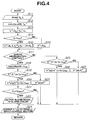
- the command vehicle speed calculation process executed at step S2 of Fig. 3 is shown by a flowchart of Fig. 4, and is executed as follows.
- controller 8 reads inter-vehicle distance L calculated at distance signal processing section 21 and host-vehicle speed V S calculated at vehicle speed signal processing section 30.
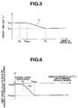
- controller 8 calculates a target time gap T H * on the basis of host-vehicle speed V S and with reference to a target time gap calculation map shown in Fig. 5.
- the target time-gap calculation map represents a relationship that target time gap T H * is maintained at an ordinary value T HU when host-vehicle speed V S is higher than a predetermined low vehicle speed V L , that target time gap T H * is gradually increased according to the decrease of host-vehicle speed V S when host-vehicle speed V S is in a range between the predetermined value V L and a maximum gradual-deceleration start speed V DMAX at which a deceleration gradual control is started, and that target time gap T H * is maintained at a control-cancel set value T HR which is larger than ordinary value T HU when host-vehicle speed V S is lower than maximum gradual-deceleration start speed V DMAX .
- controller 8 determines whether or not there is a preceding-vehicle ahead of the host-vehicle 1. This determination is executed by determining whether or not inter-vehicle distance L is smaller than or equal to a threshold L TH , which is previously set as a threshold for determining the presence or absence of a preceding-vehicle.
- L TH a threshold for determining the presence or absence of a preceding-vehicle.
- controller 8 sets command vehicle speed V* at a set vehicle-speed V SS which has been set by a driver through a not-shown vehicle-speed set switch.
- controller 8 determines whether a deceleration control is being executed or not. When the determination at step S17 is affirmative, the routine proceeds to step S18. When the determination at step S17 is negative, the routine proceeds to step S25.
- controller 8 calculates a limit value ⁇ v DW of rate of change of command vehicle speed V* on the basis of host-vehicle speed V S and with reference to a limit-value calculation map shown in Fig. 6.
- the limit-value calculation map defines a characteristic line L DW such that limit value ⁇ v DW is maintained at a relatively large negative value when host-vehicle speed V S is higher than maximum gradual-deceleration start speed V DMAX , that limit value ⁇ v DW gradually approaches zero according to the decrease of host-vehicle speed V S when host-vehicle speed V S is within a range between the predetermined value V R and maximum gradual-deceleration start speed V DMAX at which a gradual-deceleration control is started, and that limit value ⁇ V DW is maintained at a value ⁇ V DMIN near zero when host-vehicle speed V S is lower than control-cancel vehicle speed V R .
- the deceleration takes this value ⁇ V DMIN near zero, the driver of host-vehicle 1 cannot sense the deceleration of host-vehicle 1.
- controller 8 determines whether or not a value obtained by subtracting a previous command vehicle speed V*(n-1) from a present command vehicle speed V* is smaller than limit value ⁇ v DW .
- the routine proceeds to step S20.
- the routine proceeds to step S23.
- controller 8 determines whether or not host-vehicle speed V S is lower than or equal to maximum gradual-deceleration starting vehicle speed V DMAX .
- V S host-vehicle speed
- V DMAX maximum gradual-deceleration starting vehicle speed
- controller 8 outputs an alarm signal to an alarm circuit 9. Thereafter, the routine proceeds to step S24.
- controller 8 sets present command vehicle speed V*(n) at command vehicle speed V*. Thereafter, the routine jumps to step S24.
- the routine proceeds to step S26.
- the routine proceeds to step S27.
- controller 8 sets present command vehicle speed V*(n) at command vehicle speed V*. Thereafter, the routine jumps to step S24.
- controller 8 outputs present command vehicle speed V*(n) to a vehicle speed control section 30.
- step S24 the routine returns to the inter-vehicle distance control process shown in Fig. 3.
- steps S17 through S20, S23 and S24 corresponds to a deceleration gradual control means
- steps S21 and S22 and alarm circuit 9 correspond to an alarm means.
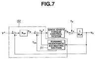
- Vehicle speed control section 50 calculates a command (target) drive-shaft torque T W * employed for bringing host-vehicle speed V S closer to command vehicle speed V*(n) inputted. More specifically, as shown in Fig. 7, vehicle speed control section 50 calculates a drive shaft torque T W by multiplying a speed control gain K SP with a difference (V*-V S ) between command vehicle speed V* and host-vehicle speed V S and by subtracting a drive-shaft torque conversion value T DH of a running resistance from drive-shaft torque T W .
- V S (K SP /M V )V* / (S+K SP /M V ).
- command throttle opening ⁇ * is obtained by calculating a command engine torque T E * relative to command drive-shaft torque T W * from the following expression (6) and by retrieving command throttle opening ⁇ * needed for generating a command engine torque T E * from an engine performance map shown in Fig. 9.
- T E * J E (dN E /dt) + T W */R T R AT R DEF .
- command throttle opening ⁇ * is greater than or equal to zero ( ⁇ * ⁇ 0)
- command drive shaft torque T W * is achieved only by the engine torque without employing brake actuators 5.
- command throttle opening ⁇ * is smaller than zero ( ⁇ * ⁇ 0)
- the throttle opening is set at zero, and a brake operation quantity for bringing drive-shaft torque T W closer to command drive-shaft torque T W * while taking account of engine torque T E .
- command drive shaft torque T W * is supplied to command engine torque calculating section 61.
- Command engine torque T E * is calculated from the expression (6) and is supplied to throttle opening calculating section 62.
- command throttle opening ⁇ * is obtained from the engine performance map representative of a relationship between command engine torque T E * and command throttle opening ⁇ * while employing engine speed as a parameter as shown in Fig. 9.
- the obtained command throttle opening ⁇ * is outputted to a throttle-opening servo system 110.
- engine torque T ELIM employed under a condition that throttle opening is zero is calculated at engine torque calculating section 63 on the basis of command throttle opening ⁇ * and engine speed N E and with reference to the engine performance map shown in Fig. 10.
- the obtained engine torque T ELIM is supplied to driving/braking force correction value calculating section 64.
- Command brake torque T B * is calculated at braking force calculating section 65 by subtracting command drive shaft torque T W * from the driving/braking force correction value T WLIM . Further, command brake hydraulic pressure P B * is calculated at braking force calculating section 65 by executing the calculation of the expression (12) and is outputted to brake hydraulic pressure servo system 100. Under a condition that there is no preceding vehicle ahead of host-vehicle 1, command brake hydraulic pressure P B * is set at zero, and the braking control is executed only by controlling the engine torque T E of host-vehicle 1.
- brake actuator 5 is feedback controlled on the basis of the difference between command brake hydraulic pressure P B * and an actual brake hydraulic pressure P BD detected by brake hydraulic pressure sensor 101.
- command throttle opening ⁇ * is supplied from drive shaft torque control section 60 to throttle opening servo system 110.
- throttle actuator 7 is feedback controlled on the basis of the difference between command throttle opening ⁇ * and an actual throttle opening ⁇ D detected by a throttle opening sensor 111.
- Vehicle speed control section 50 and drive-shaft torque control section 60 constructs driving/braking force control means.
- host-vehicle 1 follows a preceding-vehicle on an urban flat road while keeping a proper aimed inter-vehicle distance therebetween.
- the preceding-vehicle travels at a constant vehicle speed
- actual inter-vehicle distance L detected by inter-vehicle distance sensor 2 is maintained at target inter-vehicle distance L*
- command vehicle speed V*(n) calculated in inter-vehicle distance calculating section 40 from the expression (2) becomes nearly equal to host-vehicle speed V S .
- vehicle speed control section 50 calculates command drive-shaft torque T W * for maintaining host-vehicle speed V S according to the difference between command vehicle speed V*(n) and host-vehicle speed V S .
- Drive shaft torque control section 60 receives the calculated command drive-shaft torque T W *, and command engine torque calculating section 61 in drive shaft torque control section 60 calculates command engine torque T E *.
- Throttle opening calculating section 62 in drive shaft torque control section 60 calculates command throttle opening ⁇ * of a positive value ( ⁇ *>0) according to command engine torque T E *.
- the obtained command throttle opening ⁇ * is supplied to throttle opening servo system 110. Therefore, the throttle opening is controlled at a proper value by means of throttle actuator 7, and a constant speed cruise control is maintained while target inter vehicle distance L* is maintained.
- Command brake torque T B * is outputted to brake servo system 100, and therefore brake actuator 5 controls the brake hydraulic pressure at zero, that is, brake actuator 5 is put in an inoperative condition.
- command vehicle speed V*(n) calculated at inter-vehicle distance section 40 takes a value which is smaller than host-vehicle speed V S . Accordingly, command drive shaft torque T W * calculated at vehicle speed control section 50 takes a negative value.
- command brake torque T B * which is calculated at braking force calculating section 65 by adding command drive shaft torque T W * and driving/braking force correction value T WLIM calculated at driving/braking force correction value calculating section 64 on the basis of engine brake torque T ELIM calculated at engine torque calculating section 63, takes a positive value.
- Command brake hydraulic pressure P B * calculated according to command brake torque T B * takes a value corresponding to the deceleration of the preceding vehicle.
- Command brake hydraulic pressure P B * is outputted to brake hydraulic pressure servo system 100, and therefore host-vehicle 1 is put in a decelerating condition according to the deceleration of the preceding vehicle.
- target time gap T H * is gradually increased from an ordinary value T HU according to the decrease of host-vehicle speed V S .
- target inter-vehicle distance L* which is calculated from the expression (1) by executing the step S13 of Fig. 4, is set at a longer distance as compared with that in an ordinary cruising condition.
- inter-vehicle distance L is gradually increased according to the increase of the target inter-vehicle distance L* and when host-vehicle speed V S reaches gradual-deceleration start maximum speed V DMAX , target time gap T H * reaches a control-cancel set value T HR which is greater than ordinary value T HU , and is maintained at control-cancel set value T HR even if host-vehicle speed V S is decreased later. Accordingly, inter-vehicle distance L is controllably set at a longer distance as compared with that of the ordinary cruising condition.
- limit value ⁇ v DW which is calculated at step S18 in Fig. 4, gradually approaches zero from maximum value ⁇ V DMAX of a negative value according to the decrease of host-vehicle speed V S as shown in Fig. 6.
- the routine in the flowchart of Fig. 4 proceeds from step S19 to step S23 wherein present command vehicle speed V*(n) is set at command vehicle speed V* calculated at step S15 and is outputted to vehicle speed control section 50. Therefore, the deceleration of host-vehicle 1 is maintained.
- This arrangement limits a deceleration quantity of command vehicle speed V*(n).
- command drive-shaft torque T W * calculated at vehicle speed control section 50 decreases and command brake hydraulic pressure P B * calculated at drive shaft torque control section 60 also decreases according to the decrease of command drive shaft torque T W *.
- the braking force generated by brake actuator 5 is also decreased and the deceleration of host-vehicle 1 is decreased.
- step S21 When the deceleration is in a loosened condition, host-vehicle speed V S is lower than or equal to maximum gradual-deceleration starting speed V DMAX . Therefore, the routine of the flowchart in Fig. 4 proceeds from step S21 to step S22 wherein controller 8 outputs the alarm signal to alarm circuit 9 so that alarming sound is generated or alarming information is displayed by alarm circuit 9 in order to inform the driver that host-vehicle 1 is put in a gradual deceleration condition.
- command vehicle speed V* calculated at step S15 is largely limited by limit value ⁇ v DW of rate of change of command vehicle speed V*. Therefore, the braking force generated by brake actuator 5 is also decreased and the deceleration of host-vehicle 1 is decreased (loosened).
- command brake hydraulic pressure P B * calculated at drive shaft torque control section 60 takes a value near zero. Accordingly, the deceleration of host-vehicle 1 is put in a nearly zero acceleration/deceleration condition in that the driver of host-vehicle 1 cannot sense the deceleration.
- step S5 When the determination at step S5 is negative (V S ⁇ V CS ), this present time-interruption process is terminated. Accordingly, the command vehicle speed calculation process is canceled, and a driver directly controls host-vehicle 1.
- inter-vehicle distance L is increased by the acceleration of host-vehicle 1 or a lane-change after host-vehicle 1 is temporally stopped by the operation of the driver or runs at a low vehicle speed smaller than control-cancel vehicle speed V R .
- step S1 the routine proceeds from step S1 to step S2 so that the command vehicle speed calculating process is restarted.
- inter-vehicle distance sensor 2 has detected a preceding vehicle.
- inter-vehicle distance sensor 2 detects another preceding vehicle ahead of the previously detected preceding vehicle as a result that the previously detected preceding vehicle continues the acceleration or executes a lane change
- inter-vehicle distance L becomes smaller than target inter-vehicle distance L* calculated at step S13. Therefore, at step S15, controller 8 calculates command vehicle speed V* which is higher than a previous command vehicle speed V*(n-1).
- step S17 the negative determination is made at step S17, and the routine proceeds to step S25 wherein controller 8 determines whether or not the value obtained by subtracting the previous command vehicle speed V*(n-1) from the present command vehicle speed V* calculated at step S15 is greater than limit value ⁇ v UP .
- step S25 controller 8 determines whether or not the value obtained by subtracting the previous command vehicle speed V*(n-1) from the present command vehicle speed V* calculated at step S15 is greater than limit value ⁇ v UP .
- command drive torque T W * of a positive value is calculated and is supplied to drive shaft torque control section 60.
- Command engine torque calculating section 61 calculates command engine torque T E * according to command drive torque T W *.
- Throttle opening calculating section 62 receives the calculated command drive torque T W * and calculates command throttle opening ⁇ *.
- the obtained command throttle opening ⁇ * is supplied to throttle actuator 7 through throttle opening control system 100, and therefore the acceleration control is executed while the acceleration is limited.
- Vehicle speed control section 50 receives the obtained present command vehicle speed V*(n) and executes the acceleration control.
- command vehicle speed V* is set at set vehicle speed V SS by the processing of Fig. 4.
- the value, which is obtained at vehicle speed control section 50 by subtracting host-vehicle speed V S from command vehicle speed V* takes a negative value.
- command drive shaft torque T W * of a negative value is obtained according to the negative difference between host-vehicle speed V S and command vehicle speed V*.
- Driving/braking force correction value calculating section 64 calculates torque correction value T WLIM .
- Braking force calculating section 65 receives torque correction value T WLIM and calculates command brake hydraulic pressure P B *.
- command throttle opening ⁇ * calculated at throttle opening calculating section 62 takes a small value. Accordingly, a braking force due to engine brake is generated, and host-vehicle speed V S is gradually decelerated to the set vehicle speed V SS . This arrangement improves ride comfort of host-vehicle 1.
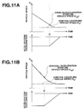
- the first embodiment according to the present invention is arranged such that the change of command vehicle speed V* is limited by limit value ⁇ v DW of the rate of change of command vehicle speed V* and that the limit value ⁇ v DW is increased from a negative value to zero according to the decrease of host-vehicle speed V S as shown in Fig. 6. Accordingly, when host-vehicle speed V S is decelerated toward control-cancel vehicle speed V R by a small deceleration as shown in Fig. 11A, a decreased quantity of command vehicle speed V* calculated at step S15 relative to previous command vehicle speed V*(n-1) is small. Therefore, the gradual deceleration control is started at a first moment t1 when limit value ⁇ v DW becomes sufficiently large, that is, when host-vehicle speed V S approaches a vehicle speed near control-cancel vehicle speed V R .
- the present invention is not limited to this arrangement and may be arranged such that gradual-deceleration starting vehicle speed V DS , by which the deceleration at control-cancel vehicle speed V R becomes nearly zero, is obtained on a presumption that a loosened rate of the deceleration is set at a constant value on the basis of the deceleration during the decelerating condition toward the control-cancel vehicle speed V R , and that the gradual deceleration control is executed by a constant gradual deceleration rate at a moment that host-vehicle speed V S reaches gradual-deceleration starting vehicle speed V DS .
- limit value ⁇ v DW is calculated from host-vehicle speed V S with reference to the limit value calculation map representative of a relationship between host-vehicle speed V S and limit value ⁇ v DW as shown in Fig. 6,
- the present invention is not limited to this and may be arranged such that a limit-value calculation map representative of a relationship between command vehicle speed V* and limit value ⁇ v DW has been previously obtained and that limit value ⁇ v DW may be calculated based on command vehicle speed V* calculated at step S15 and with reference to this limit-value calculation map.
- a second embodiment of ACC system according to the present invention.
- the second embodiment is arranged such that the gradual-deceleration starting vehicle speed relative to control-cancel vehicle speed V R is set constant, a rate of change of the deceleration is set according to the deceleration at the gradual-deceleration starting vehicle speed so that the deceleration at control-cancel vehicle speed V R is controlled at nearly zero.
- the basic construction of the second embodiment is the same as that of the first embodiment shown in Figs. 1 and 2.
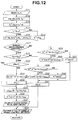
- the second embodiment is specifically arranged such that the command vehicle speed calculating process executed at inter-vehicle distance control section 40 shown in Fig. 12 is basically the same as that of the first embodiment shown in Fig. 4, except that steps S18 through S23 are omitted and are changed into the later discussed steps S31 through S41.
- the other steps of Fig. 12 are denoted by the same reference numerals of Fig. 4, and the explanation thereof is omitted herein.
- step S17 determines whether or not host-vehicle speed V S is lower than or equal to gradual-deceleration starting vehicle speed V DS .
- step S31 determines whether or not host-vehicle speed V S is lower than or equal to gradual-deceleration starting vehicle speed V DS .
- controller 8 outputs an alarm signal to alarm circuit 9. Thereafter, the routine proceeds to step S24.
- controller 8 determines whether or not a value obtained by subtracting previous command vehicle speed V*(n-1) from command vehicle speed V* calculated at step S15 is smaller than the previously set limit value ⁇ v DMAX .
- the routine proceeds to step S39 wherein present command vehicle speed V*(n) is set at a value obtained by adding limit value ⁇ v DMAX to previous command vehicle speed V*(n-1).
- the routine proceeds to step S40 wherein present command vehicle speed V*(n) is set at command vehicle speed V* calculated at step S15.
- steps S17, S24, S31 through S36 correspond to a gradual-deceleration control means
- the processing of step S37 and alarm circuit 9 correspond to an alarm means.
- step S38 it is determined whether or not the value obtained by subtracting previous command vehicle speed V*(n-1) from command vehicle speed V* calculated at step S15 is smaller than the previously set limit value ⁇ v DMAX .
- controller 8 sets present command vehicle speed V*(n) at command vehicle speed V* calculated at step S15. Further, by outputting present command vehicle speed V*(n) to speed control section 50, controller 8 executes the deceleration control.
- controller 8 sets present command vehicle speed V*(n) at the sum of previous command vehicle speed V*(n-1) and lower limit value ⁇ v DMAX . Further, by outputting present command vehicle speed V*(n) to speed control section 50, controller 8 executes the deceleration control while the change of the deceleration is limited.
- Controller 8 further calculates present command vehicle speed V*(n) by adding limit value ⁇ v DW to previous command vehicle speed V*(n-1). Furthermore, controller 8 outputs the alarm signal to alarm circuit 9 to inform the driver that gradual deceleration control has started, and outputs present command vehicle speed V*(n) to vehicle speed control section 50.
- limit value ⁇ v DW is calculated on the basis of present host-vehicle speed V S , control-cancel vehicle speed V R and deceleration G at the moment when host-vehicle speed V S reaches gradual-deceleration starting vehicle speed V DS , from the expression (14). Accordingly, limit value ⁇ v DW gradually approaches zero as host-vehicle speed V S approaches control-cancel vehicle speed V R , as shown by continuous line of Fig. 13. Then, when host-vehicle speed V S reaches control-cancel vehicle speed V R , limit value ⁇ v DW takes a value nearly equal to zero.
- limit value ⁇ v DW is gradually deceased as host-vehicle speed V S approaches control-cancel vehicle speed V R as shown by a broken line of Fig. 13. Further, when host-vehicle speed V S reaches control-cancel vehicle speed V R , suppression value ⁇ v DW takes a value nearly equal to zero. Accordingly, the following control is cancelled when the deceleration takes a value nearly equal to zero. This certainly prevents the driver from having abnormal feeling.
- limit value ⁇ v DW is calculated on the basis of host-vehicle speed V S by executing step S35 of the processing of Fig. 12, the present invention is not limited to this and may be arranged such that limit value ⁇ v DW is calculated on the basis of command vehicle speed V* calculated at step S15 instead of host-vehicle speed V S .
- FIGs. 14 and 15 there is shown a third embodiment of ACC system according to the present invention.
- the basic construction of the third embodiment is basically the same as that of the first embodiment shown in Figs. 1 and 2.
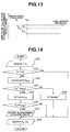
- the third embodiment is specifically arranged to gradually decrease the deceleration by limiting command brake hydraulic pressure instead of a case that the deceleration is gradually decreased by limiting command vehicle speed. More specifically, the third embodiment is arranged such that drive shaft torque control section 60 executes a command brake hydraulic pressure calculation process shown in Fig. 14 as follows.
- controller 8 reads command brake hydraulic pressure P B * calculated at braking force calculating section 65 and host-vehicle speed V S detected by vehicle speed sensor 6.
- the limit value calculation map shown in Fig. 15 has set a characteristic line which performs the following characteristics:
- controller 8 determines whether or not host-vehicle speed V S is lower than or equal to maximum gradual-deceleration starting vehicle speed V DMAX .
- the routine proceeds to step S57 wherein controller 8 outputs the alarm signal to alarm circuit 9. Then, the routine proceeds to step S59.
- the routine directly jumps to step S59.
- step S54 determines whether the determination at step S54 is negative (P B * ⁇ P BLIM ).
- controller 8 outputs the present command brake hydraulic pressure P B *(n) to brake actuator 5 through brake servo system 110. Then, the present time interruption routine is terminated.
- steps S51 through S55, S58 and S59 correspond to brake hydraulic pressure gradually decreasing control means
- steps S56 and S57 and the alarm circuit 9 correspond to alarm means.
- limit value P BLIM of command brake hydraulic pressure calculated at step S53 takes the maximum value P BMAX . Since command brake hydraulic pressure P B * is normally smaller than the maximum value P BMAX , the routine of Fig. 14 proceeds from step S54 to step S59 through step S59. Accordingly, command brake hydraulic pressure P B * read at step S51 is treated as present command brake hydraulic pressure P B *(n) and is inputted to brake actuator 5 through brake servo system 110.
- ACC system executes the deceleration control by a relatively large deceleration so that inter-vehicle distance L is brought closer to target inter-vehicle distance L*.
- limit value P BLIM calculated at step S53 is decreased according to the decrease of host-vehicle speed V S .
- the routine of Fig. 14 proceeds to step S55 wherein controller 8 sets present command brake hydraulic pressure P B *(n) at limit value P BLIM .
- This present command brake hydraulic pressure P B *(n) is supplied to brake actuator 5 through brake servo system 110.
- alarm circuit 9 generates alarm upon receiving the alarm signal from controller 8.
- the brake hydraulic pressure supplied to brake actuator 5 is gradually decreased according to the decrease of limit value P BLIM which decreases according to the decrease of host-vehicle speed V S . Therefore, the deceleration is further decreased, and at last limit value P BLIM reaches zero when host-vehicle speed V S reaches control-cancel vehicle speed V R . Accordingly, the deceleration becomes zero since the hydraulic pressure supplied to brake actuator 5 becomes zero. Under this zero deceleration condition, the following control is cancelled. Accordingly, the third embodiment according to the present invention ensures the similar advantages ensured by the first embodiment.
- FIG. 16 there is shown a fourth embodiment of ACC system according to the present invention.
- the basic construction of the fourth embodiment is basically the same as that of the first embodiment shown in Figs. 1 and 2.
- the fourth embodiment is specifically arranged such that the deceleration is loosened by limiting command brake hydraulic pressure P B * in the same manner of the second embodiment. More specifically, drive shaft torque control section 60 of controller 8 executes the command brake hydraulic pressure calculation process shown in Fig. 16 as follows.
- controller 8 reads command brake hydraulic pressure P B * and host-vehicle speed V S .
- controller 8 determines whether or not present host-vehicle speed V S is lower than or equal to gradual-deceleration starting vehicle speed V DS .
- the routine proceeds to step S64.
- the determination at step S63 is negative(V S >V DS )
- the routine proceeds to step S71.
- controller 8 stores present command brake hydraulic pressure P B * as an initial value P BS *.
- controller 8 outputs an alarm signal to alarm circuit 9. Then the routine proceeds to step S70 wherein controller 8 outputs present command brake hydraulic pressure P B *(n) to brake servo system 110.
- step S71 controller 8 determines whether or not command brake hydraulic pressure P B * is greater than a maximum limit value P BMAX of command brake hydraulic pressure P B *.
- the routine proceeds to step S72 wherein controller 8 sets present command brake hydraulic pressure P B *(n) at maximum limit value P BMAX .
- the routine proceeds to step S74 wherein controller 8 sets present command brake hydraulic pressure P B *(n) at command brake hydraulic pressure P B * read at step S61.
- step S61 through S68 and step S70 correspond to a brake-hydraulic-pressure gradual control means.
- step S69 and alarm circuit 9 correspond to an alarm means.
- the fourth embodiment according to the present invention is arranged, as is similar to the second embodiment, such that when host-vehicle speed V S becomes lower than or equal to gradual-deceleration starting vehicle speed V DS (V S ⁇ V DS ), command brake hydraulic pressure P B * is set at initial value P BS *. Accordingly, command brake hydraulic pressure P B *(n) is decreased as host-vehicle speed V S approaches control-cancel vehicle speed V R , and command brake hydraulic pressure P B takes zero when host-vehicle speed V S reaches control-cancel vehicle speed V R .
- command brake hydraulic pressure P B *(n) to be set at zero when host-vehicle speed V S reaches control-cancel vehicle speed V R regardless the magnitude of command brake hydraulic pressure P B *. Consequently, the fourth embodiment according to the present invention also ensures the advantages ensured by the second embodiment.
- the preferred embodiments according to the present invention have been shown and described to be adapted to a vehicle equipped with internal combustion engine 2 as a power source, it will be understood that the invention is not limited to this and may be adapted to a vehicle equipped with an electric motor as power source. Further, the present invention may be adapted to a hybrid vehicle which employs an internal combustion engine and an electric motor. In such a case, a regenerative braking force of the electric motor may be utilized as a braking force.
Landscapes
- Engineering & Computer Science (AREA)
- Transportation (AREA)
- Mechanical Engineering (AREA)
- Automation & Control Theory (AREA)
- Chemical & Material Sciences (AREA)
- Combustion & Propulsion (AREA)
- Controls For Constant Speed Travelling (AREA)
- Control Of Vehicle Engines Or Engines For Specific Uses (AREA)
- Control Of Driving Devices And Active Controlling Of Vehicle (AREA)
- Regulating Braking Force (AREA)
Applications Claiming Priority (2)
| Application Number | Priority Date | Filing Date | Title |
|---|---|---|---|
| JP2001231744A JP2003039980A (ja) | 2001-07-31 | 2001-07-31 | 車両用走行制御装置 |
| JP2001231744 | 2001-07-31 |
Publications (2)
| Publication Number | Publication Date |
|---|---|
| EP1281561A2 true EP1281561A2 (de) | 2003-02-05 |
| EP1281561A3 EP1281561A3 (de) | 2004-10-13 |
Family
ID=19063757
Family Applications (1)
| Application Number | Title | Priority Date | Filing Date |
|---|---|---|---|
| EP02254709A Withdrawn EP1281561A3 (de) | 2001-07-31 | 2002-07-04 | Abstandsbezogenes Fahrgeschwindigkeitsregelsystem |
Country Status (3)
| Country | Link |
|---|---|
| US (1) | US6687595B2 (de) |
| EP (1) | EP1281561A3 (de) |
| JP (1) | JP2003039980A (de) |
Cited By (2)
| Publication number | Priority date | Publication date | Assignee | Title |
|---|---|---|---|---|
| CN104071158A (zh) * | 2013-03-28 | 2014-10-01 | 富士重工业株式会社 | 车辆用控制装置 |
| US10562530B2 (en) * | 2016-12-15 | 2020-02-18 | Toyota Jidosha Kabushiki Kaisha | Driving support apparatus |
Families Citing this family (48)
| Publication number | Priority date | Publication date | Assignee | Title |
|---|---|---|---|---|
| JP3846366B2 (ja) * | 2002-02-18 | 2006-11-15 | 日産自動車株式会社 | 走行速度制御装置 |
| DE10235472B4 (de) * | 2002-08-02 | 2007-08-02 | Knorr-Bremse Systeme für Nutzfahrzeuge GmbH | Vorrichtung zur Steuerung der Bremsen eines Nutzfahrzeugs |
| JP2004123081A (ja) * | 2002-08-06 | 2004-04-22 | Honda Motor Co Ltd | 車両の追従走行装置 |
| JP2004255928A (ja) * | 2003-02-24 | 2004-09-16 | Denso Corp | 車両制御装置 |
| JP4013825B2 (ja) * | 2003-05-22 | 2007-11-28 | 日産自動車株式会社 | 車両用走行制御装置 |
| JP3991975B2 (ja) * | 2003-11-12 | 2007-10-17 | 日産自動車株式会社 | ハイブリッド変速機の変速制御装置 |
| JP4480995B2 (ja) * | 2003-12-18 | 2010-06-16 | 富士重工業株式会社 | 車両用運転支援装置 |
| EP1561629B8 (de) * | 2004-02-06 | 2012-03-07 | Nissan Motor Company Limited | System zur Vermeidung einer Abweichung von der Fahrspur |
| JP4246084B2 (ja) * | 2004-02-17 | 2009-04-02 | 日産自動車株式会社 | 車両用走行制御装置 |
| JP4172434B2 (ja) * | 2004-07-30 | 2008-10-29 | トヨタ自動車株式会社 | 車間距離制御装置 |
| JP4451315B2 (ja) * | 2005-01-06 | 2010-04-14 | 富士重工業株式会社 | 車両の運転支援装置 |
| US11225144B2 (en) | 2005-11-17 | 2022-01-18 | Invently Automotive Inc. | Vehicle power management system |
| US11390165B2 (en) | 2005-11-17 | 2022-07-19 | Invently Automotive Inc. | Electric vehicle power management system |
| US11207981B2 (en) | 2005-11-17 | 2021-12-28 | Invently Automotive Inc. | Vehicle power management system |
| US11247564B2 (en) | 2005-11-17 | 2022-02-15 | Invently Automotive Inc. | Electric vehicle power management system |
| US11267338B2 (en) | 2005-11-17 | 2022-03-08 | Invently Automotive Inc. | Electric vehicle power management system |
| US11186175B2 (en) | 2005-11-17 | 2021-11-30 | Invently Automotive Inc. | Vehicle power management system |
| US11370302B2 (en) | 2005-11-17 | 2022-06-28 | Invently Automotive Inc. | Electric vehicle power management system |
| US8712650B2 (en) | 2005-11-17 | 2014-04-29 | Invent.Ly, Llc | Power management systems and designs |
| US11214144B2 (en) | 2005-11-17 | 2022-01-04 | Invently Automotive Inc. | Electric vehicle power management system |
| US11267339B2 (en) | 2005-11-17 | 2022-03-08 | Invently Automotive Inc. | Vehicle power management system |
| US11180025B2 (en) | 2005-11-17 | 2021-11-23 | Invently Automotive Inc. | Electric vehicle power management system |
| US11351863B2 (en) | 2005-11-17 | 2022-06-07 | Invently Automotive Inc. | Vehicle power management system |
| US11186173B2 (en) | 2005-11-17 | 2021-11-30 | Invently Automotive Inc. | Electric vehicle power management system |
| US11084377B2 (en) | 2005-11-17 | 2021-08-10 | Invently Automotive Inc. | Vehicle power management system responsive to voice commands from a Gps enabled device |
| US11285810B2 (en) | 2005-11-17 | 2022-03-29 | Invently Automotive Inc. | Vehicle power management system |
| US11345236B2 (en) | 2005-11-17 | 2022-05-31 | Invently Automotive Inc. | Electric vehicle power management system |
| US11279233B2 (en) | 2005-11-17 | 2022-03-22 | Invently Automotive Inc. | Electric vehicle power management system |
| US11325468B2 (en) | 2005-11-17 | 2022-05-10 | Invently Automotive Inc. | Vehicle power management system |
| US11207980B2 (en) | 2005-11-17 | 2021-12-28 | Invently Automotive Inc. | Vehicle power management system responsive to traffic conditions |
| US11230190B2 (en) | 2005-11-17 | 2022-01-25 | Invently Automotive Inc. | Electric vehicle power management system |
| US11186174B2 (en) | 2005-11-17 | 2021-11-30 | Invently Automotive Inc. | Vehicle power management system |
| US11254211B2 (en) | 2005-11-17 | 2022-02-22 | Invently Automotive Inc. | Electric vehicle power management system |
| US11220179B2 (en) | 2005-11-17 | 2022-01-11 | Invently Automotive Inc. | Vehicle power management system determining route segment length |
| US10882399B2 (en) | 2005-11-17 | 2021-01-05 | Invently Automotive Inc. | Electric vehicle power management system |
| US11279234B2 (en) | 2005-11-17 | 2022-03-22 | Invently Automotive Inc. | Vehicle power management system |
| US8121769B2 (en) * | 2007-07-05 | 2012-02-21 | Chrysler Group Llc | Vehicle descent control |
| US8055427B2 (en) * | 2008-12-18 | 2011-11-08 | GM Global Technology Operations LLC | Method and apparatus for speed-limit following cruise control |
| JP5390714B2 (ja) * | 2009-12-21 | 2014-01-15 | ボルボ ラストバグナー アーベー | 車両のクルーズコントロール装置を制御する方法及びシステム |
| GB2508670A (en) * | 2012-12-10 | 2014-06-11 | Jaguar Land Rover Ltd | Hybrid vehicle and boost control for gradients |
| GB2508668A (en) * | 2012-12-10 | 2014-06-11 | Jaguar Land Rover Ltd | Adaptive cruise control (ACC) means for a host vehicle having regenerative and non-regenerative braking means |
| JP5756822B2 (ja) * | 2013-03-27 | 2015-07-29 | 富士重工業株式会社 | ハイブリッド車両の発電制御装置 |
| CN106314323B (zh) * | 2015-07-08 | 2019-03-08 | 大陆汽车电子(长春)有限公司 | 基于ecu和acc的联合驾驶控制方法及系统 |
| JP6728921B2 (ja) * | 2016-04-15 | 2020-07-22 | いすゞ自動車株式会社 | 運転支援装置 |
| JP6809331B2 (ja) * | 2017-03-28 | 2021-01-06 | トヨタ自動車株式会社 | 車両制御装置 |
| DE102019107412B3 (de) * | 2019-03-22 | 2020-07-09 | Zf Active Safety Gmbh | Steuerungssystem und Steuerungsverfahren zum Führen eines Kraftfahrzeugs |
| US12122341B2 (en) * | 2020-12-16 | 2024-10-22 | Cnh Industrial America Llc | Electronic braking system |
| US20240042850A1 (en) * | 2022-08-04 | 2024-02-08 | International Engine Intellectual Property Company, Llc | Systems and methods for managing gas-powered vehicle following distance |
Citations (1)
| Publication number | Priority date | Publication date | Assignee | Title |
|---|---|---|---|---|
| JP2001231744A (ja) | 2000-02-21 | 2001-08-28 | Asahi Optical Co Ltd | カプセル内視鏡 |
Family Cites Families (10)
| Publication number | Priority date | Publication date | Assignee | Title |
|---|---|---|---|---|
| US5173859A (en) * | 1990-11-05 | 1992-12-22 | General Motors Corporation | Automatic vehicle deceleration |
| US6199001B1 (en) * | 1996-12-19 | 2001-03-06 | Toyota Jidosha Kabushiki Kaisha | Control system for controlling the behavior of a vehicle based on accurately detected route information |
| JP3477015B2 (ja) * | 1996-12-25 | 2003-12-10 | トヨタ自動車株式会社 | 車間距離制御装置 |
| JPH11278096A (ja) | 1998-03-30 | 1999-10-12 | Nissan Motor Co Ltd | 車両用走行制御装置 |
| JP3661495B2 (ja) * | 1998-08-26 | 2005-06-15 | 日産自動車株式会社 | 先行車追従制御装置 |
| JP3438630B2 (ja) * | 1999-01-14 | 2003-08-18 | 日産自動車株式会社 | 車両用走行制御装置 |
| JP3610825B2 (ja) | 1999-04-28 | 2005-01-19 | 日産自動車株式会社 | 車両用走行制御装置 |
| JP3656464B2 (ja) * | 1999-06-15 | 2005-06-08 | 日産自動車株式会社 | 先行車追従制御装置 |
| JP3580184B2 (ja) * | 1999-06-30 | 2004-10-20 | 日産自動車株式会社 | 車両用追従制御装置 |
| JP3675240B2 (ja) * | 1999-07-19 | 2005-07-27 | 日産自動車株式会社 | 車両用追従制御装置 |
-
2001
- 2001-07-31 JP JP2001231744A patent/JP2003039980A/ja active Pending
-
2002
- 2002-07-04 EP EP02254709A patent/EP1281561A3/de not_active Withdrawn
- 2002-07-18 US US10/197,562 patent/US6687595B2/en not_active Expired - Fee Related
Patent Citations (1)
| Publication number | Priority date | Publication date | Assignee | Title |
|---|---|---|---|---|
| JP2001231744A (ja) | 2000-02-21 | 2001-08-28 | Asahi Optical Co Ltd | カプセル内視鏡 |
Cited By (3)
| Publication number | Priority date | Publication date | Assignee | Title |
|---|---|---|---|---|
| CN104071158A (zh) * | 2013-03-28 | 2014-10-01 | 富士重工业株式会社 | 车辆用控制装置 |
| CN104071158B (zh) * | 2013-03-28 | 2016-07-06 | 富士重工业株式会社 | 车辆用控制装置 |
| US10562530B2 (en) * | 2016-12-15 | 2020-02-18 | Toyota Jidosha Kabushiki Kaisha | Driving support apparatus |
Also Published As
| Publication number | Publication date |
|---|---|
| EP1281561A3 (de) | 2004-10-13 |
| JP2003039980A (ja) | 2003-02-13 |
| US20030028311A1 (en) | 2003-02-06 |
| US6687595B2 (en) | 2004-02-03 |
Similar Documents
| Publication | Publication Date | Title |
|---|---|---|
| EP1281561A2 (de) | Abstandsbezogenes Fahrgeschwindigkeitsregelsystem | |
| US5670953A (en) | Distance control apparatus for vehicle | |
| US6769504B2 (en) | Adaptive cruise control system for vehicle | |
| CN103707885B (zh) | 车间保持支持装置以及车间保持支持方法 | |
| EP1349131A1 (de) | Fahrzeugkollisionsverhinderungsvorrichtung | |
| EP1251024A2 (de) | Adaptives, abstandsbezogenes Fahrgeschwindigkeitsregelsystem | |
| EP1072458A2 (de) | Adaptive Steuerung der Geschwindigkeit eines Fahrzeugs | |
| JP2002089314A (ja) | 走行制御装置 | |
| JP3788240B2 (ja) | 車両用追従走行制御装置 | |
| JP3785959B2 (ja) | 車両用走行制御装置 | |
| JP3873858B2 (ja) | 追従走行制御装置 | |
| JP2008514494A (ja) | 車両の縦速度を調節する方法および装置 | |
| US6272416B1 (en) | Vehicle drive force control device | |
| JP4035925B2 (ja) | 車両用駆動力制御装置及び記録媒体 | |
| JP3728985B2 (ja) | 車両走行制御装置 | |
| JP2001027317A (ja) | 自動走行制御装置及び記録媒体 | |
| JP3890846B2 (ja) | 車両用追従走行制御装置 | |
| JP3870674B2 (ja) | 車両用追従走行制御装置 | |
| JP2004276640A (ja) | 車両用走行制御装置 | |
| JP3458663B2 (ja) | 車両駆動力制御装置 | |
| JP4060421B2 (ja) | 車間距離制御装置 | |
| JP3838097B2 (ja) | 車両用走行制御装置 | |
| JP2000313245A (ja) | 車両用走行制御装置 | |
| JP4784007B2 (ja) | 車両の運転支援装置 | |
| JP3820829B2 (ja) | 車両用追従走行制御装置 |
Legal Events
| Date | Code | Title | Description |
|---|---|---|---|
| PUAI | Public reference made under article 153(3) epc to a published international application that has entered the european phase |
Free format text: ORIGINAL CODE: 0009012 |
|
| 17P | Request for examination filed |
Effective date: 20020715 |
|
| AK | Designated contracting states |
Designated state(s): AT BE BG CH CY CZ DE DK EE ES FI FR GB GR IE IT LI LU MC NL PT SE SK TR |
|
| AX | Request for extension of the european patent |
Extension state: AL LT LV MK RO SI |
|
| PUAL | Search report despatched |
Free format text: ORIGINAL CODE: 0009013 |
|
| AK | Designated contracting states |
Kind code of ref document: A3 Designated state(s): AT BE BG CH CY CZ DE DK EE ES FI FR GB GR IE IT LI LU MC NL PT SE SK TR |
|
| AX | Request for extension of the european patent |
Extension state: AL LT LV MK RO SI |
|
| RIC1 | Information provided on ipc code assigned before grant |
Ipc: 7B 60T 7/22 B Ipc: 7B 60K 31/00 A |
|
| AKX | Designation fees paid |
Designated state(s): DE FR GB |
|
| STAA | Information on the status of an ep patent application or granted ep patent |
Free format text: STATUS: THE APPLICATION HAS BEEN WITHDRAWN |
|
| 18W | Application withdrawn |
Effective date: 20060613 |