EP1280494B1 - Badewannenlifter - Google Patents
Badewannenlifter Download PDFInfo
- Publication number
- EP1280494B1 EP1280494B1 EP01949333A EP01949333A EP1280494B1 EP 1280494 B1 EP1280494 B1 EP 1280494B1 EP 01949333 A EP01949333 A EP 01949333A EP 01949333 A EP01949333 A EP 01949333A EP 1280494 B1 EP1280494 B1 EP 1280494B1
- Authority
- EP
- European Patent Office
- Prior art keywords
- relative
- plate
- base support
- base plate
- seat
- Prior art date
- Legal status (The legal status is an assumption and is not a legal conclusion. Google has not performed a legal analysis and makes no representation as to the accuracy of the status listed.)
- Expired - Lifetime
Links
- 238000006073 displacement reaction Methods 0.000 claims description 6
- 238000003287 bathing Methods 0.000 description 3
- 238000000034 method Methods 0.000 description 3
- 238000004904 shortening Methods 0.000 description 2
- XLYOFNOQVPJJNP-UHFFFAOYSA-N water Substances O XLYOFNOQVPJJNP-UHFFFAOYSA-N 0.000 description 2
- 206010063659 Aversion Diseases 0.000 description 1
- 238000003780 insertion Methods 0.000 description 1
- 230000037431 insertion Effects 0.000 description 1
- 230000007774 longterm Effects 0.000 description 1
- 238000005096 rolling process Methods 0.000 description 1
Images








Classifications
-
- A—HUMAN NECESSITIES
- A61—MEDICAL OR VETERINARY SCIENCE; HYGIENE
- A61G—TRANSPORT, PERSONAL CONVEYANCES, OR ACCOMMODATION SPECIALLY ADAPTED FOR PATIENTS OR DISABLED PERSONS; OPERATING TABLES OR CHAIRS; CHAIRS FOR DENTISTRY; FUNERAL DEVICES
- A61G7/00—Beds specially adapted for nursing; Devices for lifting patients or disabled persons
- A61G7/10—Devices for lifting patients or disabled persons, e.g. special adaptations of hoists thereto
- A61G7/1001—Devices for lifting patients or disabled persons, e.g. special adaptations of hoists thereto specially adapted for specific applications
- A61G7/1003—Devices for lifting patients or disabled persons, e.g. special adaptations of hoists thereto specially adapted for specific applications mounted on or in combination with a bath-tub
-
- A—HUMAN NECESSITIES
- A61—MEDICAL OR VETERINARY SCIENCE; HYGIENE
- A61G—TRANSPORT, PERSONAL CONVEYANCES, OR ACCOMMODATION SPECIALLY ADAPTED FOR PATIENTS OR DISABLED PERSONS; OPERATING TABLES OR CHAIRS; CHAIRS FOR DENTISTRY; FUNERAL DEVICES
- A61G7/00—Beds specially adapted for nursing; Devices for lifting patients or disabled persons
- A61G7/10—Devices for lifting patients or disabled persons, e.g. special adaptations of hoists thereto
- A61G7/1013—Lifting of patients by
- A61G7/1019—Vertical extending columns or mechanisms
-
- A—HUMAN NECESSITIES
- A61—MEDICAL OR VETERINARY SCIENCE; HYGIENE
- A61G—TRANSPORT, PERSONAL CONVEYANCES, OR ACCOMMODATION SPECIALLY ADAPTED FOR PATIENTS OR DISABLED PERSONS; OPERATING TABLES OR CHAIRS; CHAIRS FOR DENTISTRY; FUNERAL DEVICES
- A61G7/00—Beds specially adapted for nursing; Devices for lifting patients or disabled persons
- A61G7/10—Devices for lifting patients or disabled persons, e.g. special adaptations of hoists thereto
- A61G7/1049—Attachment, suspending or supporting means for patients
- A61G7/1059—Seats
-
- A—HUMAN NECESSITIES
- A61—MEDICAL OR VETERINARY SCIENCE; HYGIENE
- A61G—TRANSPORT, PERSONAL CONVEYANCES, OR ACCOMMODATION SPECIALLY ADAPTED FOR PATIENTS OR DISABLED PERSONS; OPERATING TABLES OR CHAIRS; CHAIRS FOR DENTISTRY; FUNERAL DEVICES
- A61G7/00—Beds specially adapted for nursing; Devices for lifting patients or disabled persons
- A61G7/10—Devices for lifting patients or disabled persons, e.g. special adaptations of hoists thereto
- A61G7/1073—Parts, details or accessories
- A61G7/1074—Devices foldable for storage
Definitions
- the present invention relates to a bath tub lifter for lifting and lowering people, e.g. from and in a bathtub with a bottom plate and one opposite the base plate movable seat element.
- Bath tub lifters of this type come in many forms and Execution known and used on the market. she essentially serve as bathing aids for the elderly and especially disabled people. In doing so conventional bath tub lifters positioned in bath tubs and set.
- a seating element is approximately at the level of a Bathtub edge extended. Then the Users on this seat, for example from a wheelchair or sit on such a seat aid. It can do that Bath water should already be in the bath. Then the Seated seat element opposite the base plate, the This immerses the user in the bath water.
- the seating element can then be used again move upwards from the base plate and the Users over the edge of the bathtub in an exit position transport.
- a disadvantage of the conventional and available on the market Bath tub lifter is that these are often caused by too high Weight of the user is damaged during operation, are bad and expensive to disassemble, they should are no longer needed. They are also expensive to buy Acquisition and difficult to handle. Furthermore are these are not always stable.
- a bath tub lifter is shown and described, wherein along a seat frame Seat element is linearly movable. Between the bottom the seat element and a base plate is a inflatable or inflatable bellows provided that the linear movement and driving of the seat element is used.
- EP 1 057 467 describes an entry and exit aid for a bathtub where one is rigid, one Bathtub associated frame a seat element on and is drivable.
- a similar entry and exit aid for a bathtub shows WO 00 74624 A1, in which along a rigid Basic carrier a seat element can be moved up and down linearly is.
- the present invention is based on the object To create bath tub lifters of the type mentioned at the beginning, which eliminates the disadvantages mentioned and with which the handling of such a simple Bathtub lifters in operation as well as for transport should be significantly simplified and improved. Further In particular, long-term operation of the Bathtub lifters with high security and stability can be guaranteed.
- the seat element linearly movable with respect to a base support, the Base carrier in particular across a base plate the base plate is pivotally mounted.
- the seat element is linear along the base support movable over a sled, which over a Drive device is driven.
- This The drive device is not only with the slide, but also articulated in connection with the base plate. Furthermore, a seat plate is opposite a backrest pivoted.
- the seat plate opposite the basic carrier can be the basic carrier with the Carriage as well as with the drive device incline at the rear by a definable angle, whereby the Seat plate is decoupled from this movement. This remains approximately parallel to the base plate. So lets the seat element in the bathtub against the Retract the base plate and then the Backrest of the seat element and the basic carrier itself, the seat element up and down moved, swivel backwards. Likewise, too the drive device is inclined to the rear.
- the base plate fixed in the base plate, which are articulated in relation to the sliding carriage is from a front locking groove of the base plate Moved out, then around a joint between base plate and sliding carriage preferably around pivoted about 90 ° until the base support is approximately parallel to the base plate. Then the seat plate and Backrest between base frame and base plate folded. Then the basic carrier can be removed with a subsequent base plate over the sliding carriage move back against an end face of the bottom plate to overall to get its very short transport length.
- a Bathtub lifter shown in particular one Tilting movement of the base support in relation to the base plate, in particular a base plate by means of latches and Rocker arm secures while the seat element along the Basic carrier is movable. Only in a lowered one Position of the seat element is the seat plate on the Laid on the base plate with the slide in this position, in particular rolling the carriage by means of the rocker arm be secured. Thus, the sled becomes one linear motion secured along the base beam. On corresponding rocker arm locks in this position free of a movement of the base support to tip over against the base plate. While tipping and remains in the tipped state; the sled, in particular the seating element before the linear method secured along the base support.
- basic carrier and base plate are made in two parts are, with a base plate at the end of the base support connects that into a engages corresponding recess of the base plate and elsewhere by means of any locking device, in particular by means of a bolt lock is set releasably relative to the base plate.
- any locking device in particular by means of a bolt lock
- the Take the bath lifter apart in two parts this is This is particularly advantageous for transport, so that the Individual parts are easier to transport.
- the basic carrier with seat element and Drive device releasable in the base plate deploy. This should also be within the scope of the present Invention lie.
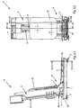
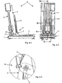
- the bath tub lifter R has a base plate 1, which preferably has four suction cups each trained foot elements 2 on a bathtub floor is secured against slipping and possibly tilting.
- Base plate 1 is mounted on a base plate 3, to which a base support 5 is pivotable about a joint 4 adjoined.
- a slot 6 is formed in the base support 5, in which a carriage 7 shown in Double arrow direction X can be moved back and forth.
- Drive device 8 On the back side, a connection to the base body 5 is provided Drive device 8, which is articulated at one end is connected to the base plate 3 and elsewhere, such as not shown here, with the carriage 7 in Intervention stands.
- a seat element 9 adjoins the carriage 7, which from a slide 10 relative to the slide 7 pivotable seat plate 11 and with the carriage 7 firmly connected backrest 12 is formed. To do that Joint 10, the seat plate 11 against the Swivel backrest 12.
- the bath tub lifter R in one extended use position shown. In this User position can be on the seat element 9 sit up and then take a bath, for example Tub can be drained.
- the sliding carriage 13 is along the illustrated Double arrow direction Y within the base plate 1 slidably arranged, as in particular in the Figures 6.1 to 6.6 is shown.
- the drive device 8 can be used as a cable pull element, Spindle operated electromechanically or hydraulically. There is no limit to the present invention his.
- the drive device 8 in particular its Cylinder element 15.2 can be pivoted about a joint 16 is mounted and the carriage 7 via a driver 17 with the cylinder element 15.1 of the drive device 8 in Intervention stands.
- Corresponding roles 18 store the Carriage 7 in guide grooves 19 of the base support 5.
- the clamping element 20 forms also a stop for a seat panel boom 21 um the seat plate 11 in an approximately parallel position Base plate 1, in particular to a surface set.
- the base plate 3 is approximately in the middle assigned nose-like guide element 22.
- the base 5 is in the fully extended position compared to the base plate 3 by means of a Locking device 23 fixed so that the Base body 5 not along the guide groove 14 around that Joint 4 is pivotable.
- the base plate 3 can be used a locking bolt, not shown here. The like. Against the base plate 1 against displacement redetectable.
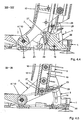
- FIG. 1.8 in enlarged partial longitudinal section according to Figure 1.5 shown.
- the seat panel boom 21 of the Seat plate 11, which is articulated around the joint 10 of the Carriage 7 is movable with the clamping element 20, which around a propeller shaft 27, also for receiving the Rollers 18 is pivotally engaged.
- This Clamping element 20, which around the drive shaft 27 is pivotally mounted preferably supports at right angles to the seat panel extension 21 at one end and is on the other hand via a pin groove 28, which within the Base support 5 approximately parallel to the guide groove 19 Recording of the rollers 18 extends over a protruding one Pin element 29 guided linearly.
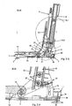
- FIGS. 2.1 and 2.2 the seat element 9 is in one Final phase of lowering to the bottom plate 1 is shown.
- the front side lies with the complete lowering of the Seat plate 11 of the seat element 9 on an increase 30 of the base plate 1 and there, as it is also in Figure 2.6 is shown, stored.
- Drive device 8 retracted or are the two Cylinder elements 15.1, 15.2 retracted into one another.
- FIGS. 2.3 and 2.4 there still stands, as is particularly the case in FIGS. 2.3 and 2.4 is shown, the seat plate extension 21 of the seat plate 11 with the clamping element 20 in connection and will pressurized.
- the propeller shaft 27 comes with a roller 18 in one end region of the guide groove 19, in which the locking device 23 is located.
- the locking device 23 is still locked and blocks a pivoting movement of the base body 5 the base plate 3 along the guide groove 14 around the joint 4th
- the two cylinder elements 15.1, 15.2 are brought together.
- the peculiarity of the present drive device 8 is here that by shortening the leash, for example a servo or electric motor, which is not shown here is shown moving apart the Cylinder elements 15.1, 15.2 is made possible. hereby there is a lifting, in particular movement of the slide 7 guaranteed upwards along the base support 5.
- a servo or electric motor which is not shown here is shown moving apart the Cylinder elements 15.1, 15.2 is made possible. hereby there is a lifting, in particular movement of the slide 7 guaranteed upwards along the base support 5.
- the present invention is in no way related to this Drive device 8 limited. There are others too Drives conceivable, such as a spindle, a hydraulic or Pneumatic cylinders or the like. Electromechanical Drives.
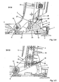
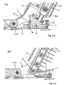
- FIGS. 3.1 to 3.5 A tax phase is shown in FIGS. 3.1 to 3.5 as further position of use of the bath tub lifter R shown and described.
- the carriage 7 with its joint 10 is still something higher than the hinge 4, but lower than in Figures 2.3 and 2.4.
- the carriage 7 is in an end position on one Support 34 on, the joints 4 and 10 of Base plate 3 and slide 7 approximately on the same Height.
- the clamping element 20 is in the pin groove 28 by means of an engaging pin element 29 around the drive shaft 27 pivoted in this way, in particular over the ends kinked pin groove 28 so that the seat plate extension 21 completely out of engagement and area of Clamping element 20 arrives.
- This will make the seat plate 11 compared to one shown in Figures 5.1 to 5.4 Tilting movement in relation to the tilting movement of slide 7 and decoupled base carrier 5.
- the seat plate 11 remains parallel and independent of a tilting movement of the base support 5.
- the drive shaft 27 overlaps the guide element 22 of the base plate 3.
- the slide 33 is the Locking device 23 by acting on the roller 18, which also the carriage 7 in this position in the The guide groove 19 can be moved outwards and unlocks the locking device 23.
- the base device 5 By moving the The base device 5 can then be driven by the drive device 8 and drive device 8 pivot, the Drive device 8, as shown in Figure 5.3 around the joint 16 and the carriage 7 around the joint 4 or 10 is pivotable.
- the drive shaft 27 the carriage 7 and thus the base 5 along the Guide element 22 out.
- the cylinders 15.1 and 15.2 of the drive device 8 are completely retracted.
- FIG. 2.1 Another advantage with the present invention is as mentioned above, an extremely advantageous one Transport position, as shown in Figures 6.1 to 6.6 is shown. This is done in the manner described above from a position of use, such as that shown in FIG. 2.1 is shown, the seat plate 11 around the joint 10 given away to the backrest 12, then the Sliding carriage 13 with base plate 3 from the locking groove 26 the end face 24 is moved out, so that the locking element 25th the base plate 3 is exposed. Then you can Base plate 3 relative to the sliding carriage 13 in this way pivot that the base support 5 approximately parallel to Base plate 1 is. A subsequent push back of the sliding carriage 13 with its joint 4 against the End face 24 of the base plate 1 enables a very short and compact transport position of the bath tub lifter R. This can then be easily used for transport purposes transport.
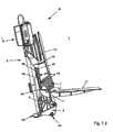
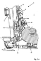
- FIG. 7.1 another is preferred Embodiment of the present invention Bathtub lifter R shown, which is roughly that corresponds to previous embodiment.
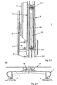
- His Base plate 1 with foot elements 2 is preferred formed in one piece, with an end face Area 35, as it also enlarges in particular shown in cross section in Figure 7.3 emerges in the Base plate 1 has an end recess 36 formed in it.
- the bottom plate 1 is a support bed 37 assigned, which serves to receive the base plate 3.
- a hose handle 38 can be held the base plate 3, in particular the base support 5 with Drive device 8 may be provided.
- a handle bottle 39 be provided at the other end of the base support 5.
- Basic carrier 5 with drive device 8 seat element 9 is releasable and fixable with the base plate 1.
- the base plate 3 with a locking lug 40 engages precisely in the recess 36 of the base plate 1.
- the lower contour of the base plate on the face side lies 3 on the support bed 37 and fits there held.
- Bolt lock 41 engages after the insertion of the Base plate 3 in the bottom plate 1 laterally and releasably locks the base plate 3 with the Base plate 1.
- the recess 36 as a detent 40, in which case correspondingly analog in the base plate 3 corresponding trough is formed, which with a corresponding latch of the base plate 1 cooperates, to fix the base plate 3 in relation to the base plate 1 or define.
- the base support 5 connects to the base plate 3, especially designed as double against each other arranged and spaced C-rails, as here is partially shown.
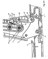
- Figure 7.1 is shown, the base support 5 by means of a Bolt 42 pivotable relative to the base plate 3 mounted, with a flange 43 of the base support 5 Has elongated hole 44 through which a further bolt 45th the base plate 3 engages and a tilting movement around the Allows bolt 42 guided in slot 44. On the process the tilting movement will be referred to later.
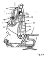
- FIG. 2 Another peculiarity of the present invention shows FIG. 2, with a clamping piece 46 on the slide 7 is pivotally mounted about a bolt 47 and by means of a cam 48, which is not closer to here shown cam track of the base support 5, in particular the C-rails is guided to pivot about the bolt 47 is stored. At the end, the clamping piece 46 strikes one Stop 49 of the pivotally mounted about the joint 10 Seat plate 11 and holds it in an approximately horizontal Position.
- FIG. 7.2 Rollers 18 shown in a C-rail, not shown of the base support 5 are linear and a Movement of the carriage 7 up and down through to leave the drive device 8.
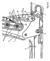
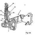
- FIG. 7 In the perspective view according to Figure 7.7 is the carriage 7 shown with backrest 12, the two extension arms 50 in the manner described above with the Drive device are connected. On the side of the Extension arms 50 of the carriage 7 are linear with each other attached a plurality of rollers 18, these back and forth within a C-profile of the base support 5 can be moved here.
- the joint 10 pivotally connects the Seat plate 11 with the carriage 7, the stop 49 with the clamping piece 46 in the manner described above in Engagement is about a horizontal position of the seat plate 11 to set or set.
- top roller 18 has an upward Cover 51 is assigned, which prevents, for example. Objects, clothing, fingers of a human Hand or the like. Between rollers 18 and not here shown C-rail or base bracket 5 clamped can be.
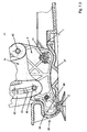
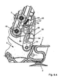
- the bolt 52 is also with a cam track 54 and Cam pocket 55 provided in which a rocker arm 56th is stored.
- One end of the rocker arm 56 engages Rocker arm pin 57 in the cam pocket 55.
- a center pin 58 is assigned to the rocker arm 56.
- the rocker arm 56 has a holding trough 59 which to determine the carriage 7, which is only indicated here, in particular the bottom roll 18 is used.
- On Spring element 60 pulls the rocker arm 56 upwards.
- the carriage 7 can be linearly high along the C-rail or the base support and move down, whereby the base support 5 prevented against the base plate 3, in particular is secured.
- Roll 18 pivots and secures the movement of the Carriage 7 against linear movement along the Basic carrier 5.
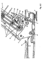
- one end of the base support 5 and another attacks on the base plate 3 is another Tilting the base support 5 relative to the base plate 1 guaranteed.
- the Centering pin 58 of the rocker arm 56 along the cam track 54 of the bolt 52, the bolt 52 around the bolt 53 is pivoted when the base support 5 is tilted.
- the bar 52 lies on the outside Rocker arm pin 57 of the rocker arm 56 on and holds permanently the roller 18 of the carriage 7 by means of their Holding trough 59 firmly.
Landscapes
- Health & Medical Sciences (AREA)
- Nursing (AREA)
- Life Sciences & Earth Sciences (AREA)
- Animal Behavior & Ethology (AREA)
- General Health & Medical Sciences (AREA)
- Public Health (AREA)
- Veterinary Medicine (AREA)
- Devices For Medical Bathing And Washing (AREA)
- Magnetic Heads (AREA)
- Glass Compositions (AREA)
Description
| Positionszahlenliste | |||||
| 1 | Bodenplatte | 34 | Auflager | 67 | |
| 2 | Fusselement | 35 | Bereich | 68 | |
| 3 | Grundplatte | 36 | Mulde | 69 | |
| 4 | Gelenk | 37 | Auflagebett | 70 | |
| 5 | Grundträger | 38 | Schlauchgriff | 71 | |
| 6 | Schlitz | 39 | Grifflasche | 72 | |
| 7 | Schlitten | 40 | Rastnase | 73 | |
| 8 | Antriebseinrichtung | 41 | Bolzenverriegelung | 74 | |
| 9 | Sitzelement | 42 | Bolzen | 75 | |
| 10 | Gelenk | 43 | Flansch | 76 | |
| 11 | Sitzplatte | 44 | Langloch | 77 | |
| 12 | Rückenlehne | 45 | Bolzen | 78 | |
| 13 | Schiebeschlitten | 46 | Klemmstück | 79 | |
| 14 | Führungsnut | 47 | Bolzen | ||
| 15 | Zylinderelement | 48 | Nocke | ||
| 16 | Gelenk | 49 | Anschlag | R | Badewannenlifter |
| 17 | Mitnehmer | 50 | Auslegearm | ||
| 18 | Rollen | 51 | Abdeckung | α | Winkel |
| 19 | Führungsnuten | 52 | Riegel | ||
| 20 | Klemmelement | 53 | Bolzen | H | Hub |
| 21 | Sitzplattenausleger | 54 | Nockenbahn | ||
| 22 | Führungelement | 55 | Nockentasche | X | Doppelpfeilrichtung |
| 23 | Verriegelungseinrichtung | 56 | Kipphebel | Y | Doppelpfeilrichtung |
| 24 | Stirnseite | 57 | Kipphebelbolzen | ||
| 25 | Rastelement | 58 | Zentrierbolzen | ||
| 26 | Rastnut | 59 | Haltemulde | ||
| 27 | Gelenkwelle | 60 | Federelement | ||
| 28 | Zapfennut | 61 | |||
| 29 | Zapfenelement | 62 | |||
| 30 | Erhöhung | 63 | |||
| 31 | Rollenpaket | 64 | |||
| 32 | Rollenscheiben | 65 | |||
| 33 | Schieber | 66 |
Claims (23)
- Badewannenlifter zum Anheben und Ablassen von Personen, bspw. aus und in eine Badewanne mit einer Bodenplatte (1) und einem gegenüber der Bodenplatte (1) bewegbaren Sitzelement (9),
dadurch gekennzeichnet, dass das Sitzelement (9) gegenüber einem Grundträger (5) linear verfahrbar und dieser gegenüber der Bodenplatte (1) verschwenkbar ist und der Grundträger (5) mit linear verfahrbarem Sitzelement (9) in einer abgesenkten Lage des Sitzelementes (9) gegenüber der Bodenplatte (1) und gegenüber einer Sitzplatte (11) des Sitzelementes (9) um einen wählbaren Winkel (α) zurückneigbar ist. - Badewannenlifter zum Anheben und Ablassen von Personen, bspw. aus und in eine Badewanne mit einer Bodenplatte (1) und einem gegenüber der Bodenplatte (1) bewegbaren Sitzelement (9), dadurch gekennzeichnet, dass ein Grundträger (5) mit linear verfahrbaren Sitzelement (9) an eine Grundplatte (3) anschliesst und beim Auflegen einer Sitzplatte (11) auf der Bodenplatte (1) mittels zumindest einem Riegelelement (52) ein lineares Bewegen des Sitzelementes (9) verhindert und ein Abkippen des Grundträgers (5) gegenüber der Bodenplatte (1) freigegeben ist.
- Badewannenlifter nach Anspruch 1 oder 2, dadurch gekennzeichnet, dass ein Grundträger (5) mit linear verfahrbarem Sitzelement (9) an eine Grundplatte (3) anschliesst, und mittels zumindest einem Riegelelement (52) ein Abkippen des Grundträgers (5) beim linearen Verfahren des Sitzelementes (9) verhindert ist.
- Badewannenlifter nach wenigstens einem der Ansprüche 1 bis 3, dadurch gekennzeichnet, dass ein Grundträger (5) mit linear verfahrbarem Sitzelement (9) sowie eine Antriebseinrichtung (8) gegen eine Grundplatte (3) verschwenkbar gelagert ist, wobei die Grundplatte (3) fest oder lösbar an die Bodenplatte (1) anschliessbar ist.
- Badewannenlifter nach wenigstens einem der Ansprüche 1 bis 4, dadurch gekennzeichnet, dass das Sitzelement (9) aus einer Sitzplatte (11) und einer Rückenlehne (12) gebildet ist, welche mit einem im Grundträger (5) linear bewegbar angeordneten Schlitten (7) in Verbindung stehen.
- Badewannenlifter nach Anspruch 4 oder 5, dadurch gekennzeichnet, dass der Grundträger (5) mittig einen Schlitz (6) aufweist, in welchem der Schlitten (7) linear verfahrbar und über eine Antriebsrichtung (8) bewegbar ist.
- Badewannenlifter nach wenigstens einem der Ansprüche 1 bis 6, dadurch gekennzeichnet, dass während eines linearen Verfahrens des Sitzelementes (9) entlang des Grundträgers (5) zwischen einer abgesenkten und einer ausgefahrenen Lage eine Verriegelungseinrichtung (23) ein nach hinten Neigen des Grundträgers (5) gegenüber einer mit der Bodenplatte (1) fixierten Grundplatte (3) verriegelt und nach Absenken der Sitzplatte (11) gegenüber der Bodenplatte (1) ein Entriegeln der Verriegelungseinrichtung (23) erfolgt, wobei mittels der Antriebseinrichtung (8) der Grundträger (5) gegenüber der Grundplatte (3) um den Winkel (α) neigbar ist.
- Badewannenlifter nach wenigstens einem der Ansprüche 1 bis 7, dadurch gekennzeichnet, dass der Grundträger (5) gegenüber der Grundplatte (3) verschwenkbar ist, wobei eine Verschwenkbewegung des Grundträgers (5) von einer Schwenkbewegung der Sitzplatte (11) entkoppelt ist.
- Badewannenlifter nach Anspruch 8, dadurch gekennzeichnet, dass zur Entkopplung einer Schwenkbewegung des Grundträgers (5) gegenüber der Sitzplatte (11) ein Klemmelement (20/46) aus einem Wirkbereich eines Sitzplattenauslegers (21) oder Anschlages (49) ausfahrbar ist.
- Badewannenlifter nach wenigstens einem der Ansprüche 1 bis 9, dadurch gekennzeichnet, dass die Sitzplatte (11) gegenüber einer Rückenlehne (12) des Sitzelementes (9) klappbar ist.
- Badewannenlifter nach wenigstens einem der Ansprüche 5 bis 10, dadurch gekennzeichnet, dass eine Antriebseinrichtung (8) einends gelenkig mit der Grundplatte (3) und andernends mit dem gegenüber dem Grundträger (5) bewegbaren Schlitten (7) angeordnet, insbesondere gelagert ist.
- Badewannenlifter nach wenigstens einem der Ansprüche 9 bis 11, dadurch gekennzeichnet, dass das Klemmelement (20/46) schwenkbar gegenüber dem Schlitten (7) angeordnet ist, und linear in einer Zapfennut (28) oder Nockenbahn zur Steuerung einer Schwenkbewegung mit dem Grundträger (5) zusammenwirkt.
- Badewannenlifter nach Anspruch 11 oder 12, dadurch gekennzeichnet, dass die Antriebseinrichtung (8) zum Bewegen des Schlittens (7) spindelartig erfolgt.
- Badewannenlifter nach wenigstens einem der Ansprüche 9 bis 13, dadurch gekennzeichnet, dass die Verriegelungseinrichtung (23) mit dem Klemmelement (20) zum Lösen eines Schiebers (33) zum Neigen des Grundträgers (5) gegenüber der Grundplatte (3) mittels der Antriebseinrichtung (8) erfolgt.
- Badewannenlifter nach wenigstens einem der Ansprüche 5 bis 13, dadurch gekennzeichnet, dass der Schlitten (7), insbesondere der Grundträger (5) bei abgelassenen Sitzelement (9), insbesondere Sitzplatte (11) um das Gelenk (4) um den Winkel (α) verschwenkbar, insbesondere neigbar ist.
- Badewannenlifter nach wenigstens einem der Ansprüche 2 bis 15, dadurch gekennzeichnet, dass die Grundplatte (3) gelenkig verschwenkbar an einen Schiebeschlitten (7) anschliesst, welcher einends stirnseitig zum Festlegen in die Bodenplatte (1) eingreift und nach einem Ausgreifen, insbesondere linearen Verschieben gegenüber der Grundplatte (3) verschwenkbar, insbesondere klappbar und linear verfahrbar ist.
- Badewannenlifter nach wenigstens einem der Ansprüche 3 bis 15, dadurch gekennzeichnet, dass der Grundplatte (3) zumindest ein Riegel (52) zugeordnet ist, welcher gelenkig um einen Bolzen (53) gelagert ist, wobei der Riegel (52) mit einer Nockentasche (55) und einer Nockenbahn (54) versehen ist.
- Badewannenlifter nach wenigstens einem der Ansprüche 2 bis 15, dadurch gekennzeichnet, dass dem zumindest einen Riegel (52) ein Kipphebel (56) zugeordnet ist, welcher ein Kipphebelbolzen (57), ein Zentrierbolzen (58) und eine Haltemulde (59) aufweist
- Badewannenlifter nach Anspruch 18, dadurch gekennzeichnet, dass der Kipphebelbolzen (57) zum Verhindern eines Abkippens des Grundträgers (5) gegenüber der Bodenplatte (1) in die Nockentasche (55) eingreift, während der Zentrierbolzen (58) in der Nockenbahn (54) geführt ist und eine lineare Bewegung des Schlittens 7, insbesondere der zumindest einen Rolle 18 des Schlittens 7 gegenüber dem Kipphebel (56), insbesondere dessen Haltemulde (59) freigegeben ist.
- Badewannenlifter nach Anspruch 18 oder 19, dadurch gekennzeichnet, dass durch Bewegen des Schlittens 7, insbesondere der zumindest einen Rolle (18) gegen die Haltemulde (59) des Kipphebels (56) der Kipphebelbolzen (57) aus der Nockentasche (55) herausbewegbar und ein Abkippen des Grundträgers (5) gegenüber der Bodenplatte (1) bzw. gegenüber der Grundplatte (3) freigegeben ist und die Haltemulde (59) die zumindest eine Rolle (18) zumindest teilweise umfängt um eine lineare Bewegung des Schlittens 7 zu blockieren, insbesondere festzulegen.
- Badewannenlifter nach wenigstens einem der Ansprüche 18 bis 20, dadurch gekennzeichnet, dass in einer abgesenkten Lage des Sitzelementes (9), insbesondere der Sitzplatte (11), zumindest eine unterste Rolle (18) den Kipphebel (56) zum Freigeben einer Kippbewegung des Grundträgers (5) und gleichzeitigen Sichern des Schlittens (7) gegenüber linearem Bewegen betätigt.
- Badewannenlifter nach wenigstens einem der Ansprüche 4 bis 21, dadurch gekennzeichnet, dass an die Grundplatte (3) der Grundträger (5) anschliesst und die Grundplatte (3) mit zumindest einer Rastnase (40) versehen ist, die in eine Mulde (36) der Bodenplatte (1) eingreift, wobei zumindest eine Bolzenverriegelung (41) zum wiederlösbaren Festlegen der Grundplatte (3) gegenüber der Bodenplatte (1) vorgesehen ist.
- Badewannenlifter nach wenigstens einem der Ansprüche 20 bis 22, dadurch gekennzeichnet, dass zumindest einer obersten Rolle (18) eine Abdeckung (51) zugeordnet ist.
Applications Claiming Priority (3)
| Application Number | Priority Date | Filing Date | Title |
|---|---|---|---|
| DE10022327 | 2000-05-09 | ||
| DE10022327 | 2000-05-09 | ||
| PCT/EP2001/005296 WO2001085087A1 (de) | 2000-05-09 | 2001-05-09 | Badewannenlifter |
Publications (2)
| Publication Number | Publication Date |
|---|---|
| EP1280494A1 EP1280494A1 (de) | 2003-02-05 |
| EP1280494B1 true EP1280494B1 (de) | 2004-08-04 |
Family
ID=7641161
Family Applications (1)
| Application Number | Title | Priority Date | Filing Date |
|---|---|---|---|
| EP01949333A Expired - Lifetime EP1280494B1 (de) | 2000-05-09 | 2001-05-09 | Badewannenlifter |
Country Status (5)
| Country | Link |
|---|---|
| EP (1) | EP1280494B1 (de) |
| JP (1) | JP2003532497A (de) |
| AT (1) | ATE272379T1 (de) |
| DE (2) | DE50103116D1 (de) |
| WO (1) | WO2001085087A1 (de) |
Cited By (2)
| Publication number | Priority date | Publication date | Assignee | Title |
|---|---|---|---|---|
| CN102178590A (zh) * | 2011-05-27 | 2011-09-14 | 山东育达医疗设备有限公司 | 多功能手术台的升降机构 |
| CN102178591A (zh) * | 2011-05-05 | 2011-09-14 | 山东育达医疗设备有限公司 | 多功能电动手术台 |
Families Citing this family (7)
| Publication number | Priority date | Publication date | Assignee | Title |
|---|---|---|---|---|
| DE20008205U1 (de) | 2000-05-09 | 2001-09-27 | eureha GmbH, 88131 Lindau | Badewannenlifter |
| WO2003075818A2 (en) * | 2002-03-13 | 2003-09-18 | Gordon Basil Nel | Bath lift |
| FR2860710B1 (fr) * | 2003-10-13 | 2006-08-04 | A2Ci | Dispositif pour faciliter l'acces a une baignoire a des personnes a mobilite reduite |
| DE102010017748B4 (de) | 2010-02-12 | 2019-05-02 | Eureha Gmbh | Antrieb für einen Badewannenlift |
| JP6335414B2 (ja) * | 2014-04-18 | 2018-05-30 | 株式会社いうら | 入浴介助用車椅子 |
| EP3130322B1 (de) * | 2015-08-11 | 2018-05-23 | Invacare International Sàrl | Badehebevorrichtung |
| FI127759B (fi) * | 2017-08-30 | 2019-02-15 | Liikuntavieteri Oy | Henkilökohotin ja menetelmä henkilökohottimen käyttövoiman tuottamiseksi |
Family Cites Families (4)
| Publication number | Priority date | Publication date | Assignee | Title |
|---|---|---|---|---|
| GB2014446B (en) * | 1977-12-22 | 1983-01-19 | Garman D E T | Bathing supports |
| DE19701591A1 (de) * | 1997-01-18 | 1998-07-23 | Aquatec Peter Schmidt Gmbh | Badelift für Senioren und Behinderte |
| DE19925140A1 (de) * | 1999-06-02 | 2000-12-07 | Walter Gobbers | Ein- und Ausstiegshilfe für eine Badewanne |
| WO2000074624A1 (de) * | 1999-06-02 | 2000-12-14 | Dieter Gobbers | Ein- und ausstiegshilfe für eine badewanne |
-
2001
- 2001-05-09 EP EP01949333A patent/EP1280494B1/de not_active Expired - Lifetime
- 2001-05-09 JP JP2001581742A patent/JP2003532497A/ja not_active Withdrawn
- 2001-05-09 DE DE50103116T patent/DE50103116D1/de not_active Expired - Lifetime
- 2001-05-09 AT AT01949333T patent/ATE272379T1/de not_active IP Right Cessation
- 2001-05-09 DE DE10122578A patent/DE10122578A1/de not_active Withdrawn
- 2001-05-09 WO PCT/EP2001/005296 patent/WO2001085087A1/de not_active Ceased
Cited By (2)
| Publication number | Priority date | Publication date | Assignee | Title |
|---|---|---|---|---|
| CN102178591A (zh) * | 2011-05-05 | 2011-09-14 | 山东育达医疗设备有限公司 | 多功能电动手术台 |
| CN102178590A (zh) * | 2011-05-27 | 2011-09-14 | 山东育达医疗设备有限公司 | 多功能手术台的升降机构 |
Also Published As
| Publication number | Publication date |
|---|---|
| ATE272379T1 (de) | 2004-08-15 |
| JP2003532497A (ja) | 2003-11-05 |
| DE50103116D1 (de) | 2004-09-09 |
| WO2001085087A1 (de) | 2001-11-15 |
| EP1280494A1 (de) | 2003-02-05 |
| DE10122578A1 (de) | 2002-02-28 |
Similar Documents
| Publication | Publication Date | Title |
|---|---|---|
| DE836236C (de) | Anordnung zum Heben und Transport von bettlaegerigen kranken Personen | |
| DE68929186T2 (de) | Fahrzeuge und Ladebordwände | |
| DE69009806T2 (de) | Zusammenklappbarer Kinderstuhl. | |
| DE3590309C2 (de) | Vorrichtung für Betten zum Wenden von Patienten | |
| EP0707843B1 (de) | Vorrichtung zum Einsetzen in eine Badewanne oder dergleichen als Ein- und Ausstiegshilfe | |
| DE3136078A1 (de) | Drei-weg-liegesitz | |
| DE2458811C3 (de) | Vorrichtung an einem Lastkraftwagen | |
| DE102021114748A1 (de) | Mechanismus zum Umwandeln eines Möbelstücks von einer Sitz- in eine Liegeposition | |
| DE19701591A1 (de) | Badelift für Senioren und Behinderte | |
| DE19911872A1 (de) | Rückezug zum Rücken von Kurzholz und Langholz | |
| DE10122578A1 (de) | Badewannenlifter | |
| EP0380621B1 (de) | Badehilfe | |
| DE29824011U1 (de) | Bett, insbesondere Kranken- oder Pflegebett | |
| DE4220803C2 (de) | Rolltreppeneinrichtung | |
| DE3602105A1 (de) | Krankenhebe- und transporteinrichtung | |
| DE69707917T2 (de) | Fahrzeugausrüstung zur transferierung und befestigung eines in einen rollstuhl umwandelaren sitzes | |
| DE69512258T2 (de) | Versetzvorrichtung für personen | |
| DE2837665A1 (de) | Sessel | |
| DE4222939C1 (de) | ||
| EP0853936B1 (de) | Badelift für Senioren und Behinderte | |
| DE19649576A1 (de) | Regulierbare Abstützvorrichtung | |
| DE19535918C2 (de) | Fahrradträger | |
| DE3540486A1 (de) | Vorrichtung zum verschwenken eines einzelsitzes eines kraftfahrzeuges | |
| DE3844317C2 (de) | ||
| DE9218839U1 (de) | Ausziehbare Bettcouch |
Legal Events
| Date | Code | Title | Description |
|---|---|---|---|
| PUAI | Public reference made under article 153(3) epc to a published international application that has entered the european phase |
Free format text: ORIGINAL CODE: 0009012 |
|
| 17P | Request for examination filed |
Effective date: 20021011 |
|
| AK | Designated contracting states |
Designated state(s): AT BE CH CY DE DK ES FI FR GB GR IE IT LI LU MC NL PT SE TR |
|
| 17Q | First examination report despatched |
Effective date: 20030318 |
|
| GRAP | Despatch of communication of intention to grant a patent |
Free format text: ORIGINAL CODE: EPIDOSNIGR1 |
|
| GRAS | Grant fee paid |
Free format text: ORIGINAL CODE: EPIDOSNIGR3 |
|
| GRAA | (expected) grant |
Free format text: ORIGINAL CODE: 0009210 |
|
| AK | Designated contracting states |
Kind code of ref document: B1 Designated state(s): AT BE CH CY DE DK ES FI FR GB GR IE IT LI LU MC NL PT SE TR |
|
| PG25 | Lapsed in a contracting state [announced via postgrant information from national office to epo] |
Ref country code: IT Free format text: LAPSE BECAUSE OF FAILURE TO SUBMIT A TRANSLATION OF THE DESCRIPTION OR TO PAY THE FEE WITHIN THE PRESCRIBED TIME-LIMIT;WARNING: LAPSES OF ITALIAN PATENTS WITH EFFECTIVE DATE BEFORE 2007 MAY HAVE OCCURRED AT ANY TIME BEFORE 2007. THE CORRECT EFFECTIVE DATE MAY BE DIFFERENT FROM THE ONE RECORDED. Effective date: 20040804 Ref country code: TR Free format text: LAPSE BECAUSE OF FAILURE TO SUBMIT A TRANSLATION OF THE DESCRIPTION OR TO PAY THE FEE WITHIN THE PRESCRIBED TIME-LIMIT Effective date: 20040804 Ref country code: NL Free format text: LAPSE BECAUSE OF FAILURE TO SUBMIT A TRANSLATION OF THE DESCRIPTION OR TO PAY THE FEE WITHIN THE PRESCRIBED TIME-LIMIT Effective date: 20040804 Ref country code: FI Free format text: LAPSE BECAUSE OF FAILURE TO SUBMIT A TRANSLATION OF THE DESCRIPTION OR TO PAY THE FEE WITHIN THE PRESCRIBED TIME-LIMIT Effective date: 20040804 Ref country code: FR Free format text: LAPSE BECAUSE OF FAILURE TO SUBMIT A TRANSLATION OF THE DESCRIPTION OR TO PAY THE FEE WITHIN THE PRESCRIBED TIME-LIMIT Effective date: 20040804 |
|
| REG | Reference to a national code |
Ref country code: GB Ref legal event code: FG4D Free format text: NOT ENGLISH |
|
| REG | Reference to a national code |
Ref country code: CH Ref legal event code: EP |
|
| GBT | Gb: translation of ep patent filed (gb section 77(6)(a)/1977) |
Effective date: 20040804 |
|
| REG | Reference to a national code |
Ref country code: IE Ref legal event code: FG4D Free format text: GERMAN |
|
| REF | Corresponds to: |
Ref document number: 50103116 Country of ref document: DE Date of ref document: 20040909 Kind code of ref document: P |
|
| PG25 | Lapsed in a contracting state [announced via postgrant information from national office to epo] |
Ref country code: GR Free format text: LAPSE BECAUSE OF FAILURE TO SUBMIT A TRANSLATION OF THE DESCRIPTION OR TO PAY THE FEE WITHIN THE PRESCRIBED TIME-LIMIT Effective date: 20041104 Ref country code: DK Free format text: LAPSE BECAUSE OF FAILURE TO SUBMIT A TRANSLATION OF THE DESCRIPTION OR TO PAY THE FEE WITHIN THE PRESCRIBED TIME-LIMIT Effective date: 20041104 Ref country code: SE Free format text: LAPSE BECAUSE OF FAILURE TO SUBMIT A TRANSLATION OF THE DESCRIPTION OR TO PAY THE FEE WITHIN THE PRESCRIBED TIME-LIMIT Effective date: 20041104 |
|
| PG25 | Lapsed in a contracting state [announced via postgrant information from national office to epo] |
Ref country code: ES Free format text: LAPSE BECAUSE OF FAILURE TO SUBMIT A TRANSLATION OF THE DESCRIPTION OR TO PAY THE FEE WITHIN THE PRESCRIBED TIME-LIMIT Effective date: 20041115 |
|
| NLV1 | Nl: lapsed or annulled due to failure to fulfill the requirements of art. 29p and 29m of the patents act | ||
| PG25 | Lapsed in a contracting state [announced via postgrant information from national office to epo] |
Ref country code: CY Free format text: LAPSE BECAUSE OF FAILURE TO SUBMIT A TRANSLATION OF THE DESCRIPTION OR TO PAY THE FEE WITHIN THE PRESCRIBED TIME-LIMIT Effective date: 20050509 Ref country code: LU Free format text: LAPSE BECAUSE OF NON-PAYMENT OF DUE FEES Effective date: 20050509 |
|
| PG25 | Lapsed in a contracting state [announced via postgrant information from national office to epo] |
Ref country code: LI Free format text: LAPSE BECAUSE OF NON-PAYMENT OF DUE FEES Effective date: 20050531 Ref country code: MC Free format text: LAPSE BECAUSE OF NON-PAYMENT OF DUE FEES Effective date: 20050531 Ref country code: CH Free format text: LAPSE BECAUSE OF NON-PAYMENT OF DUE FEES Effective date: 20050531 Ref country code: BE Free format text: LAPSE BECAUSE OF NON-PAYMENT OF DUE FEES Effective date: 20050531 |
|
| PLBE | No opposition filed within time limit |
Free format text: ORIGINAL CODE: 0009261 |
|
| STAA | Information on the status of an ep patent application or granted ep patent |
Free format text: STATUS: NO OPPOSITION FILED WITHIN TIME LIMIT |
|
| 26N | No opposition filed |
Effective date: 20050506 |
|
| EN | Fr: translation not filed | ||
| BERE | Be: lapsed |
Owner name: *EUREHA G.M.B.H. Effective date: 20050531 |
|
| REG | Reference to a national code |
Ref country code: CH Ref legal event code: PL |
|
| PGFP | Annual fee paid to national office [announced via postgrant information from national office to epo] |
Ref country code: AT Payment date: 20060515 Year of fee payment: 6 |
|
| PGFP | Annual fee paid to national office [announced via postgrant information from national office to epo] |
Ref country code: IE Payment date: 20070524 Year of fee payment: 7 |
|
| BERE | Be: lapsed |
Owner name: *EUREHA G.M.B.H. Effective date: 20050531 |
|
| PG25 | Lapsed in a contracting state [announced via postgrant information from national office to epo] |
Ref country code: PT Free format text: LAPSE BECAUSE OF NON-PAYMENT OF DUE FEES Effective date: 20050104 |
|
| PG25 | Lapsed in a contracting state [announced via postgrant information from national office to epo] |
Ref country code: AT Free format text: LAPSE BECAUSE OF NON-PAYMENT OF DUE FEES Effective date: 20070509 |
|
| REG | Reference to a national code |
Ref country code: IE Ref legal event code: MM4A |
|
| PG25 | Lapsed in a contracting state [announced via postgrant information from national office to epo] |
Ref country code: IE Free format text: LAPSE BECAUSE OF NON-PAYMENT OF DUE FEES Effective date: 20080509 |
|
| PGFP | Annual fee paid to national office [announced via postgrant information from national office to epo] |
Ref country code: DE Payment date: 20101130 Year of fee payment: 10 |
|
| PGFP | Annual fee paid to national office [announced via postgrant information from national office to epo] |
Ref country code: GB Payment date: 20101130 Year of fee payment: 10 |
|
| GBPC | Gb: european patent ceased through non-payment of renewal fee |
Effective date: 20110509 |
|
| REG | Reference to a national code |
Ref country code: DE Ref legal event code: R119 Ref document number: 50103116 Country of ref document: DE Effective date: 20111201 |
|
| PG25 | Lapsed in a contracting state [announced via postgrant information from national office to epo] |
Ref country code: GB Free format text: LAPSE BECAUSE OF NON-PAYMENT OF DUE FEES Effective date: 20110509 |
|
| PG25 | Lapsed in a contracting state [announced via postgrant information from national office to epo] |
Ref country code: DE Free format text: LAPSE BECAUSE OF NON-PAYMENT OF DUE FEES Effective date: 20111201 |